EP0273191B1 - Liquid distributor for mass and heat transfer columns - Google Patents
Liquid distributor for mass and heat transfer columns Download PDFInfo
- Publication number
- EP0273191B1 EP0273191B1 EP87117197A EP87117197A EP0273191B1 EP 0273191 B1 EP0273191 B1 EP 0273191B1 EP 87117197 A EP87117197 A EP 87117197A EP 87117197 A EP87117197 A EP 87117197A EP 0273191 B1 EP0273191 B1 EP 0273191B1
- Authority
- EP
- European Patent Office
- Prior art keywords
- recesses
- tongues
- openings
- drip
- walls
- Prior art date
- Legal status (The legal status is an assumption and is not a legal conclusion. Google has not performed a legal analysis and makes no representation as to the accuracy of the status listed.)
- Expired - Lifetime
Links
- 239000007788 liquid Substances 0.000 title claims abstract description 23
- 210000002105 tongue Anatomy 0.000 claims abstract description 14
- 238000010276 construction Methods 0.000 abstract 1
- XLYOFNOQVPJJNP-UHFFFAOYSA-N water Substances O XLYOFNOQVPJJNP-UHFFFAOYSA-N 0.000 description 5
- 230000015572 biosynthetic process Effects 0.000 description 2
- 238000004519 manufacturing process Methods 0.000 description 1
- 238000004806 packaging method and process Methods 0.000 description 1
- 230000000717 retained effect Effects 0.000 description 1
- 238000000926 separation method Methods 0.000 description 1
Images


Classifications
-
- B—PERFORMING OPERATIONS; TRANSPORTING
- B01—PHYSICAL OR CHEMICAL PROCESSES OR APPARATUS IN GENERAL
- B01D—SEPARATION
- B01D3/00—Distillation or related exchange processes in which liquids are contacted with gaseous media, e.g. stripping
- B01D3/008—Liquid distribution
Definitions
- the invention relates to a liquid distributor for mass and heat exchange columns, which have a main distributor with parallel channels in the form of trough-like troughs with perforations in their walls for liquid outlet, longitudinal guide vanes with downwardly directed drainage pipes being provided on the outer sides of the trough walls.
- Liquid distributors are known as tube and channel distributors and also in a combination of the two.
- EPA-A-112 978 describes such a combination of distribution channels with attached tubes, which means complex production and is only suitable for larger amounts of liquid.
- DE-C-3 306 636 shows a channel distributor with wall perforations and drip tongues as well as hooked-in guide wires, which results in complex assembly.
- DE-C-2 945 103 and DE-C-3 409 524 also show channel distributors with perforations in the wall, drip-off tongues and, in addition, particularly curtain walls with tongues for liquid drainage, which, due to their diversity, result in fine distribution, but are also very complex and prone to failure and also require larger amounts of liquid.
- the object of the invention is now a liquid distributor to create in a simple and robust design, which are suitable for both smaller and larger amounts of liquid and work effectively in all areas and are less prone to failure.
- the liquid distributor according to the preamble of claim 1 is characterized in that the baffles, which are placed without spacing, are equipped with recesses which at least encompass the perforations from below, the drip-off tongues also being arranged between the cutouts offset from the recesses.
- the baffles which are placed without spacing, are equipped with recesses which at least encompass the perforations from below, the drip-off tongues also being arranged between the cutouts offset from the recesses.
- baffles may have flaps on the perforations on the channel walls, the cutouts of which form the holes completely encompassing recesses, as a result of which the formation of a water jet is avoided when excess water escapes and this is also distributed in width.
- the liquid distributor for mass and heat exchange columns consists of a main distributor 2 arranged above the media packaging in the column container 1 with underlying parallel channels in the form of trough-like troughs 3, the walls of which have 4 perforations 5 for liquid outlet .
- guide plates 6 are respectively fixedly placed along the longitudinal side, which on the one hand have the perforations 5 with recesses 7 from below and thus center the liquid running off on the channel wall downwards in individual runs, the cutouts 8, on the other hand, arranged downward on the guide plates 6, offset from the recesses 7, taking over the liquid line to the intermediate, protruding drip tongues 9.
- the separation of the liquid drain that takes place through the perforations 5 is retained and there can be no merging and uncontrolled drainage along the lower channel edges.
- the guide plate 6 on the outer walls 4 extends laterally around the perforations 5 and 5a to 5d, encompassing them approximately half way up (5) and forms intermediate boundaries, while in the exemplary embodiment according to FIG. 8 the guide plate 6a grips the same between the perforations 5a on the channel wall 4, the tabs 10 being cut out over the same and the recess 7a lying upwards during the opening, while the cutouts 8 remain with the drip-in tongues 9 as in the previous embodiments.
- the drip-off tongues 9, as not particularly shown here can be alternately turned on and off and also remain vertically in between.
Landscapes
- Chemical & Material Sciences (AREA)
- Chemical Kinetics & Catalysis (AREA)
- Vaporization, Distillation, Condensation, Sublimation, And Cold Traps (AREA)
- Feeding, Discharge, Calcimining, Fusing, And Gas-Generation Devices (AREA)
- Physical Or Chemical Processes And Apparatus (AREA)
- Details Of Heat-Exchange And Heat-Transfer (AREA)
- Heat-Exchange Devices With Radiators And Conduit Assemblies (AREA)
Abstract
Description
Die Erfindung bezieht sich auf einen Flüssigkeitsverteiler für Stoff- und Wärmeaustauschkolonnen, welche einen Hauptverteiler mit parallelen Kanälen in Form trogartiger Rinnen mit Lochungen in deren Wandungen zum Flüssigkeitsaustritt aufweisen, wobei an den Außenseiten der Rinnenwandungen längslaufende Leitbleche mit nach unten ausgerichteten Abtropzungen vorgesehen sind.The invention relates to a liquid distributor for mass and heat exchange columns, which have a main distributor with parallel channels in the form of trough-like troughs with perforations in their walls for liquid outlet, longitudinal guide vanes with downwardly directed drainage pipes being provided on the outer sides of the trough walls.
Es sind Flüssigkeitsverteiler als Röhrchen- und Rinnenverteiler sowie auch in Kombination von beidem bekannt. So zeigt z.B. die EPA-A-112 978 eine solche Kombination von Verteilerrinnen mit angesetzten Röhrchen, was eine aufwendige Herstellung bedeutet und sich nur für größere Flüssigkeitsmengen eignet. Die DE-C-3 306 636 zeigt einen Rinnenverteiler mit Wandlochungen und Abropfzungen sowie eingehängten Führungsdrähten, wodurch sich eine aufwendige Montage ergibt. Die DE-C-2 945 103 und DE-C-3 409 524 zeigen ebenfalls Rinnenverteiler mit Wandlochungen, Abtropfzungen und darüber hinaus besonders vorgehängten Wänden mit Zungen zur Flüsigkeitsableitung, welche durch ihre Vielfalt zur Feinverteilung führen, aber dadurch auch sehr aufwendig und störanfällig sind und auch größere Flüssigkeitsmengen voraussetzen.Liquid distributors are known as tube and channel distributors and also in a combination of the two. For example, EPA-A-112 978 describes such a combination of distribution channels with attached tubes, which means complex production and is only suitable for larger amounts of liquid. DE-C-3 306 636 shows a channel distributor with wall perforations and drip tongues as well as hooked-in guide wires, which results in complex assembly. DE-C-2 945 103 and DE-C-3 409 524 also show channel distributors with perforations in the wall, drip-off tongues and, in addition, particularly curtain walls with tongues for liquid drainage, which, due to their diversity, result in fine distribution, but are also very complex and prone to failure and also require larger amounts of liquid.
Aufgabe der Erfindung ist es nun Flüssigkeitsverteiler in einfacher und robuster Bauweise zu schaffen, welche sich sowohl für kleinere als auch für größere Flüssigkeitsmengen eignen und in allen Bereichen effektiv arbeiten und wenig störanfällig sind.The object of the invention is now a liquid distributor to create in a simple and robust design, which are suitable for both smaller and larger amounts of liquid and work effectively in all areas and are less prone to failure.
Hierzu kennzeichnet sich der Flüssigkeitsverteiler nach dem Oberbegriff des Anspruchs 1 dadurch, daß die ohne Abstand aufgesetzten Leitbleche mit Ausnehmungen ausgestattet sind, welche die Lochungen zumindest von unten umfangen, wobei ferner die Abtropfzungen zwischen den zu Ausnehmungen versetzt befindlichen Ausschnitten angeordnet sind. Hierdurch wird ein unkontrollierbares Ablaufen der Flüsigkeit nach dem Austreten aus den Wandlochungen und Sammelen am Trogunterrand vermieden; vielmehr wird jeweils ein Ableiten über die abgesetzten Ausnehmungen am Leitblech und Überführen an die Abtropfzungen unter Mithilfe der versetzten Ausschnitte am unteren Rand des längslaufenden Leitblechs erreicht.For this purpose, the liquid distributor according to the preamble of claim 1 is characterized in that the baffles, which are placed without spacing, are equipped with recesses which at least encompass the perforations from below, the drip-off tongues also being arranged between the cutouts offset from the recesses. This avoids an uncontrollable drainage of the liquid after exiting the wall perforations and collecting at the lower edge of the trough; rather, a discharge is achieved in each case via the recessed recesses on the guide plate and transfer to the drip-off tongues with the aid of the offset cutouts at the lower edge of the longitudinal guide plate.
Zusätzlich können die Leitbleche über den Lochungen an den Rinnenwandungen ausgestellte Lappen aufweisen, deren Ausschnitt die Lochungen vollständig umfangende Ausnehmungen bilden, wodurch bei austretendem Mehrwasser die Ausbildung eines Wasserstrahls vermieden und dieser auch in die Breite verteilt wird.In addition, the baffles may have flaps on the perforations on the channel walls, the cutouts of which form the holes completely encompassing recesses, as a result of which the formation of a water jet is avoided when excess water escapes and this is also distributed in width.
Weitere Einzelheiten des Flüssigkeitsverteilers gemäß der Erfindung ergeben sich aus den nachfolgend dargestellten und beschriebenen, bevorzugten Ausführungsbeispielen; in der Zeichnung zeigen:
- Fig. 1
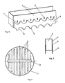
- die Gesamtansicht eines Flüssigkeitsverteilers,
- Fig. 2 und 3
- die perspektivische Ansicht und den Querschnitt einer Verteilerrinne,
- Fig. 4 bis 7
- die Seitenansicht von weiteren Ausführungsformen und
- Fig. 8
- die Seitenansicht einer Ausführungsform mit ausgestellten Lappen.
- Fig . 1
- the overall view of a liquid distributor,
- Fig . 2 and 3
- the perspective view and the cross section of a distribution channel,
- Fig . 4 to 7
- the side view of further embodiments and
- Fig . 8th
- the side view of an embodiment with flaps issued.
Wie aus der Gesamtansicht nach Fig. 1 ersichtlich wird, besteht hier der Flüssigkeitsverteiler für Stoff- und Wärmeaustauschkolonnen aus einem über der Medienverpackung im Kolonnenbehälter 1 angeordneten Hauptverteiler 2 mit darunterliegenden parallelen Kanälen in Form von trogartigen Rinnen 3, deren Wandungen 4 Lochungen 5 zum Flüssigkeitsaustritt aufweisen.As can be seen from the overall view according to FIG. 1, here the liquid distributor for mass and heat exchange columns consists of a
An den Außenseiten der Rinnenwandungen 4 sind gemäß der Erfindung entsprechend Fig. 2 ff jeweils längsseitig Leitbleche 6 ohne Abstand fest aufgesetzt, welche einerseits die Lochungen 5 mit Ausnehmungen 7 von unten umfangen und damit die an der Rinnenwandung ablaufende Flüssigkeit jeweils zu einzelnen Abläufen nach unten zentrieren, wobei die andererseits an den Leitblechen 6 nach unten, versetzt zu den Ausnehmungen 7 angeordneten Ausschnitten 8 die Flüssigkeitsleitung zu dem dazwischenliegenden, überstehenden Abtropfzungen 9 übernehmen. Somit bleibt die durch die Lochungen 5 erfolgende Vereinzelung des Flüssigkeitsablaufes erhalten und es kann kein Zusammenführen und unkontrolliertes Ablaufen entlang der unteren Rinnenkanten erfolgen.On the outer sides of the channel walls 4, according to the invention according to FIGS. 2 ff,
In den Fig. 4 bis 7 sind sodann weitere Ausführungsformen solcher Rinnenwandungen 4 mit Lochungen als Rundlöcher 5a, Langlöcher 5b, Randeinschnitte 5c und V-Ausschnitte 5d gezeigt mit jeweils längsseits aufgebrachten Leitblechen 6 mit nach oben gerichteten Sammler-Ausnehmungen 7 und nach unten, versetzt angeordneten Leit-Ausschnitten 8 mit zwischenliegenden Abtropfzungen 9.4 to 7 further embodiments of such channel walls 4 with perforations as
In Fig. 8 sind schließlich eine Rinnenwandung 4 mit Lochungen 5a dargestellt mit einem Leitblech 6a dessen Ausnehmungen 7a an den Lochungen 5a ausgestellte Lappen 10 aufweisen, während die Ausschnitte 8 hierzu versetzt nach unten die dazwischenliegenden Abtropfzungen 9, wie bisher bilden. Die ausgestellten Lappen 10 dienen dazu die Ausbildung eines Wasserstrahls bei austretendem Mehrwasser an den Lochungen 5a zu vermeiden und dieses Wasser in die Breite zu verteilen.8 finally shows a channel wall 4 with
Bei den Ausführungsbeispielen von Fig. 2 bis 7 reicht an den Außenwänden 4 das Leitblech 6 seitlich der Lochungen 5 und 5a bis 5d diese umgreifend etwa auf halbe Höhe derselben (5) und bildet zwischenliegende Abgrenzungen, während beim Ausführungsbeispiel nach Fig. 8 das Leitblech 6a zwischen den Lochungen 5a an der Rinnenwandung 4 dieselben umgreift, wobei über denselben die Lappen 10 ausgeschnitten sind und beim Ausstellen die Ausnehmung 7a nach oben liegen, während die Ausschnitte 8 mit dazwischenliegenden Abtropfzungen 9, wie bei den vorhergehenden Ausführungsformen verbleiben. Schließlich können die Abtropfzungen 9, wie hier nicht besonders dargestellt, wechselweise ein/ und ausgestellt und dazwischen auch senkrecht verbleibend sein.In the exemplary embodiments of FIGS. 2 to 7, the
Claims (4)
- Liquid distributor for mass and heat transfer columns comprising a master distributor (2) having parallel channels in the form of trough-like ducts (3) with openings (5, 5a, 5b, 5c, 5d) in the walls thereof to allow liquids to flow out, with longitudinally extending guiding panels (6, 6a) with downwardly directed drip tongues (7, 7a) being provided at the external sides of the duct walls (4), characterized in that the tightly mounted guiding panels (6, 6a) are provided with recesses (7. 7a) encompassing at least the bottom portion of the opening (5, 5a, 5b, 5c, 5d), and that the drip tongues (9) are arranged between cut-out sections (9) arranged in a staggered fashion relative to the recesses (7, 7a).
- The apparatus according to claim 1, characterized in that the guiding panels (6a) have flaps (10) protruding above the openings (5a) from the walls of the ducts (outer wall 4), the cut-out sections of said flaps forming recesses (7a) completely covering the openings (5a).
- The apparatus according to claim 1, characterized in that the guiding panels (6) between the recesses (7) encompassing the openings (5, 5a, 5b, 5c, 5d) at the duct walls (4) reach with their intermediate border sections to approximately halfway up the openings (5, 5a, 5b, 5c, 5d).
- Apparatus according to any of the preceding claims, characterized in that the drip tongues (9) located below the upper recesses (7, 7a) are alternately protruding and inwardly bent.
Priority Applications (1)
| Application Number | Priority Date | Filing Date | Title |
|---|---|---|---|
| AT87117197T ATE65706T1 (en) | 1986-11-29 | 1987-11-21 | LIQUID DISTRIBUTORS FOR MASS AND HEAT EXCHANGE COLUMNS. |
Applications Claiming Priority (2)
| Application Number | Priority Date | Filing Date | Title |
|---|---|---|---|
| DE3640886A DE3640886C1 (en) | 1986-11-29 | 1986-11-29 | Liquid distributor for mass and heat exchange columns |
| DE3640886 | 1986-11-29 |
Publications (2)
| Publication Number | Publication Date |
|---|---|
| EP0273191A1 EP0273191A1 (en) | 1988-07-06 |
| EP0273191B1 true EP0273191B1 (en) | 1991-07-31 |
Family
ID=6315127
Family Applications (1)
| Application Number | Title | Priority Date | Filing Date |
|---|---|---|---|
| EP87117197A Expired - Lifetime EP0273191B1 (en) | 1986-11-29 | 1987-11-21 | Liquid distributor for mass and heat transfer columns |
Country Status (4)
| Country | Link |
|---|---|
| EP (1) | EP0273191B1 (en) |
| AT (1) | ATE65706T1 (en) |
| DE (1) | DE3640886C1 (en) |
| ES (1) | ES2024478B3 (en) |
Families Citing this family (7)
| Publication number | Priority date | Publication date | Assignee | Title |
|---|---|---|---|---|
| DE4321743A1 (en) * | 1992-06-30 | 1994-03-17 | Fraunhofer Ges Forschung | Heat and material exchange reactor |
| DE19524774A1 (en) * | 1995-07-07 | 1997-01-09 | Montz Gmbh Julius | Drain tongue for liquid distributors |
| DE19626895A1 (en) * | 1996-07-04 | 1998-01-08 | Linde Ag | Liquid distributor for a mass transfer column |
| FR2771025B1 (en) * | 1997-11-17 | 2000-01-28 | Air Liquide | CORRUGATED STRIP FOR CROSS-CORRUGATED TRIM AND ITS APPLICATION TO ON-BOARD DISTILLATION COLUMNS |
| DE10141526A1 (en) | 2001-08-24 | 2003-04-17 | Zae Bayern Bayerisches Zentrum Fuer Angewandte Energieforschung Ev | Smallest amount of liquid distributor |
| CN103521161A (en) * | 2013-09-30 | 2014-01-22 | 天津大学 | Reinforced bending groove type liquid distributor |
| WO2023107578A1 (en) * | 2021-12-07 | 2023-06-15 | Carbon Engineering Ltd. | Capturing carbon dioxide |
Family Cites Families (8)
| Publication number | Priority date | Publication date | Assignee | Title |
|---|---|---|---|---|
| DE2945103C2 (en) * | 1979-11-08 | 1985-08-08 | Julius Montz Gmbh, 4010 Hilden | Liquid distributor for a countercurrent column |
| US4264538A (en) * | 1980-05-14 | 1981-04-28 | Norton Company | Liquid distributor |
| DE3141930C2 (en) * | 1981-10-22 | 1986-07-10 | Julius Montz Gmbh, 4010 Hilden | Distribution tray for an exchange column |
| CH658198A5 (en) * | 1983-01-04 | 1986-10-31 | Sulzer Ag | LIQUID DISTRIBUTOR IN A SUBSTANCE AND HEAT EXCHANGE COLUMN. |
| DE3306636A1 (en) * | 1983-02-25 | 1984-08-30 | Julius Montz Gmbh, 4010 Hilden | Liquid distributor for a countercurrent column |
| DE3346857A1 (en) * | 1983-12-23 | 1985-07-04 | Paul Rauschert Gmbh & Co Kg, 8644 Pressig | LIQUID DISTRIBUTOR FOR MATERIAL REPLACEMENT COLONES |
| DE3409524C1 (en) * | 1984-03-15 | 1985-09-05 | Julius Montz Gmbh, 4010 Hilden | Liquid distributor for a counter-current column |
| CH663904A5 (en) * | 1984-08-17 | 1988-01-29 | Kuehni Ag | LIQUID DISTRIBUTOR FOR A TUBE EXCHANGE COLUMN. |
-
1986
- 1986-11-29 DE DE3640886A patent/DE3640886C1/en not_active Expired
-
1987
- 1987-11-21 ES ES87117197T patent/ES2024478B3/en not_active Expired - Lifetime
- 1987-11-21 AT AT87117197T patent/ATE65706T1/en not_active IP Right Cessation
- 1987-11-21 EP EP87117197A patent/EP0273191B1/en not_active Expired - Lifetime
Also Published As
| Publication number | Publication date |
|---|---|
| ES2024478B3 (en) | 1992-03-01 |
| EP0273191A1 (en) | 1988-07-06 |
| DE3640886C1 (en) | 1988-06-09 |
| ATE65706T1 (en) | 1991-08-15 |
Similar Documents
| Publication | Publication Date | Title |
|---|---|---|
| EP0112978B1 (en) | Liquid distributor for a mass and heat exchange column | |
| EP0282753B1 (en) | Apparatus for the uniform distribution of a liquid on a transfer section of a mass and heat transfer column | |
| EP0151693B1 (en) | Material exchange column | |
| DE2248273C2 (en) | Plate heat exchanger | |
| DE2919462C2 (en) | Device for evenly distributing liquids on column surfaces | |
| DE2943687C2 (en) | Trough-like device for collecting and distributing the liquid for a countercurrent column | |
| DE69615141T2 (en) | Improved liquid distributor for packed columns | |
| DE2402807A1 (en) | COOLING TOWER WITH INCLINED THIN FILM BED | |
| DE69412578T2 (en) | HIGH-PERFORMANCE TUB FOR GAS LIQUID CONTACT DEVICE | |
| DE2250873A1 (en) | LAMELLA SEPARATOR FOR SLIM TANKS | |
| EP0231841A1 (en) | Apparatus for the uniform distribution of a liquid containing solid particles on a cross area | |
| DE2222269A1 (en) | RECTIFICATION TOWER OR COLUMN | |
| EP0273191B1 (en) | Liquid distributor for mass and heat transfer columns | |
| CH663904A5 (en) | LIQUID DISTRIBUTOR FOR A TUBE EXCHANGE COLUMN. | |
| EP0374443B1 (en) | Device for carrying a packing and for collecting or distibuting a liquid in a mass or heat exchange transfer vessel | |
| DE69412800T2 (en) | WATER DISTRIBUTION FROM COOLING TOWER | |
| EP0162993A1 (en) | Wet or combined wet-dry cooling tower | |
| DE3731988C3 (en) | Reactor for the treatment of a gas | |
| DE2102424A1 (en) | Liquid distributor for a mass transfer column | |
| DE3409524C1 (en) | Liquid distributor for a counter-current column | |
| DE3021202C2 (en) | Device for sprinkling trickle plates with cooling water to be cooled | |
| EP0255039B1 (en) | Under floor heating | |
| EP0371475A1 (en) | Splashing device for heat and mass exchangers, particularly cooling towers | |
| DE602004007029T2 (en) | CATALYTIC REACTOR UNDER PSEUDO-ISOTHERMIC CONDITIONS | |
| CH670051A5 (en) |
Legal Events
| Date | Code | Title | Description |
|---|---|---|---|
| PUAI | Public reference made under article 153(3) epc to a published international application that has entered the european phase |
Free format text: ORIGINAL CODE: 0009012 |
|
| AK | Designated contracting states |
Kind code of ref document: A1 Designated state(s): AT BE CH ES FR GB IT LI LU NL |
|
| 17P | Request for examination filed |
Effective date: 19881130 |
|
| 17Q | First examination report despatched |
Effective date: 19900712 |
|
| ITF | It: translation for a ep patent filed | ||
| GRAA | (expected) grant |
Free format text: ORIGINAL CODE: 0009210 |
|
| AK | Designated contracting states |
Kind code of ref document: B1 Designated state(s): AT BE CH ES FR GB IT LI LU NL |
|
| REF | Corresponds to: |
Ref document number: 65706 Country of ref document: AT Date of ref document: 19910815 Kind code of ref document: T |
|
| ET | Fr: translation filed | ||
| REG | Reference to a national code |
Ref country code: ES Ref legal event code: FG2A Ref document number: 2024478 Country of ref document: ES Kind code of ref document: B3 |
|
| GBT | Gb: translation of ep patent filed (gb section 77(6)(a)/1977) | ||
| PLBE | No opposition filed within time limit |
Free format text: ORIGINAL CODE: 0009261 |
|
| STAA | Information on the status of an ep patent application or granted ep patent |
Free format text: STATUS: NO OPPOSITION FILED WITHIN TIME LIMIT |
|
| 26N | No opposition filed | ||
| EPTA | Lu: last paid annual fee | ||
| REG | Reference to a national code |
Ref country code: GB Ref legal event code: IF02 |
|
| PGFP | Annual fee paid to national office [announced via postgrant information from national office to epo] |
Ref country code: GB Payment date: 20021029 Year of fee payment: 16 |
|
| PGFP | Annual fee paid to national office [announced via postgrant information from national office to epo] |
Ref country code: NL Payment date: 20021118 Year of fee payment: 16 Ref country code: FR Payment date: 20021118 Year of fee payment: 16 |
|
| PGFP | Annual fee paid to national office [announced via postgrant information from national office to epo] |
Ref country code: AT Payment date: 20021119 Year of fee payment: 16 |
|
| PGFP | Annual fee paid to national office [announced via postgrant information from national office to epo] |
Ref country code: CH Payment date: 20021122 Year of fee payment: 16 Ref country code: BE Payment date: 20021122 Year of fee payment: 16 |
|
| PGFP | Annual fee paid to national office [announced via postgrant information from national office to epo] |
Ref country code: LU Payment date: 20021125 Year of fee payment: 16 |
|
| PGFP | Annual fee paid to national office [announced via postgrant information from national office to epo] |
Ref country code: ES Payment date: 20021126 Year of fee payment: 16 |
|
| PG25 | Lapsed in a contracting state [announced via postgrant information from national office to epo] |
Ref country code: LU Free format text: LAPSE BECAUSE OF NON-PAYMENT OF DUE FEES Effective date: 20031121 Ref country code: GB Free format text: LAPSE BECAUSE OF NON-PAYMENT OF DUE FEES Effective date: 20031121 Ref country code: AT Free format text: LAPSE BECAUSE OF NON-PAYMENT OF DUE FEES Effective date: 20031121 |
|
| PG25 | Lapsed in a contracting state [announced via postgrant information from national office to epo] |
Ref country code: ES Free format text: LAPSE BECAUSE OF NON-PAYMENT OF DUE FEES Effective date: 20031122 |
|
| PG25 | Lapsed in a contracting state [announced via postgrant information from national office to epo] |
Ref country code: LI Free format text: LAPSE BECAUSE OF NON-PAYMENT OF DUE FEES Effective date: 20031130 Ref country code: CH Free format text: LAPSE BECAUSE OF NON-PAYMENT OF DUE FEES Effective date: 20031130 Ref country code: BE Free format text: LAPSE BECAUSE OF NON-PAYMENT OF DUE FEES Effective date: 20031130 |
|
| BERE | Be: lapsed |
Owner name: *RASCHIG A.G. Effective date: 20031130 |
|
| PG25 | Lapsed in a contracting state [announced via postgrant information from national office to epo] |
Ref country code: NL Free format text: LAPSE BECAUSE OF NON-PAYMENT OF DUE FEES Effective date: 20040601 |
|
| GBPC | Gb: european patent ceased through non-payment of renewal fee |
Effective date: 20031121 |
|
| REG | Reference to a national code |
Ref country code: CH Ref legal event code: PL |
|
| PG25 | Lapsed in a contracting state [announced via postgrant information from national office to epo] |
Ref country code: FR Free format text: LAPSE BECAUSE OF NON-PAYMENT OF DUE FEES Effective date: 20040730 |
|
| NLV4 | Nl: lapsed or anulled due to non-payment of the annual fee |
Effective date: 20040601 |
|
| REG | Reference to a national code |
Ref country code: FR Ref legal event code: ST |
|
| REG | Reference to a national code |
Ref country code: ES Ref legal event code: FD2A Effective date: 20031122 |
|
| PG25 | Lapsed in a contracting state [announced via postgrant information from national office to epo] |
Ref country code: IT Free format text: LAPSE BECAUSE OF NON-PAYMENT OF DUE FEES;WARNING: LAPSES OF ITALIAN PATENTS WITH EFFECTIVE DATE BEFORE 2007 MAY HAVE OCCURRED AT ANY TIME BEFORE 2007. THE CORRECT EFFECTIVE DATE MAY BE DIFFERENT FROM THE ONE RECORDED. Effective date: 20051121 |