EP0212330B1 - Terminal clamp or splicing ear for electrical apparatus - Google Patents
Terminal clamp or splicing ear for electrical apparatus Download PDFInfo
- Publication number
- EP0212330B1 EP0212330B1 EP86110254A EP86110254A EP0212330B1 EP 0212330 B1 EP0212330 B1 EP 0212330B1 EP 86110254 A EP86110254 A EP 86110254A EP 86110254 A EP86110254 A EP 86110254A EP 0212330 B1 EP0212330 B1 EP 0212330B1
- Authority
- EP
- European Patent Office
- Prior art keywords
- plug
- connector according
- contact part
- connector
- additional contact
- Prior art date
- Legal status (The legal status is an assumption and is not a legal conclusion. Google has not performed a legal analysis and makes no representation as to the accuracy of the status listed.)
- Expired - Lifetime
Links
- 239000004020 conductor Substances 0.000 claims abstract description 42
- 230000001681 protective effect Effects 0.000 claims abstract description 35
- 238000003780 insertion Methods 0.000 claims description 18
- 230000037431 insertion Effects 0.000 claims description 18
- 238000004873 anchoring Methods 0.000 claims description 11
- 210000002105 tongue Anatomy 0.000 claims description 9
- 239000002184 metal Substances 0.000 claims description 5
- 230000000149 penetrating effect Effects 0.000 claims description 4
- 210000001331 nose Anatomy 0.000 claims description 2
- 238000005406 washing Methods 0.000 claims description 2
- 239000000725 suspension Substances 0.000 claims 1
- 238000004519 manufacturing process Methods 0.000 abstract description 4
- 230000014759 maintenance of location Effects 0.000 description 2
- 239000003973 paint Substances 0.000 description 2
- 230000006978 adaptation Effects 0.000 description 1
- 238000005452 bending Methods 0.000 description 1
- 230000000295 complement effect Effects 0.000 description 1
- 238000010276 construction Methods 0.000 description 1
- 238000011161 development Methods 0.000 description 1
- 230000018109 developmental process Effects 0.000 description 1
- 238000005516 engineering process Methods 0.000 description 1
- 239000004922 lacquer Substances 0.000 description 1
- 238000000034 method Methods 0.000 description 1
- 238000007790 scraping Methods 0.000 description 1
Images


Classifications
-
- H—ELECTRICITY
- H01—ELECTRIC ELEMENTS
- H01R—ELECTRICALLY-CONDUCTIVE CONNECTIONS; STRUCTURAL ASSOCIATIONS OF A PLURALITY OF MUTUALLY-INSULATED ELECTRICAL CONNECTING ELEMENTS; COUPLING DEVICES; CURRENT COLLECTORS
- H01R9/00—Structural associations of a plurality of mutually-insulated electrical connecting elements, e.g. terminal strips or terminal blocks; Terminals or binding posts mounted upon a base or in a case; Bases therefor
- H01R9/22—Bases, e.g. strip, block, panel
- H01R9/24—Terminal blocks
- H01R9/2491—Terminal blocks structurally associated with plugs or sockets
-
- H—ELECTRICITY
- H01—ELECTRIC ELEMENTS
- H01R—ELECTRICALLY-CONDUCTIVE CONNECTIONS; STRUCTURAL ASSOCIATIONS OF A PLURALITY OF MUTUALLY-INSULATED ELECTRICAL CONNECTING ELEMENTS; COUPLING DEVICES; CURRENT COLLECTORS
- H01R4/00—Electrically-conductive connections between two or more conductive members in direct contact, i.e. touching one another; Means for effecting or maintaining such contact; Electrically-conductive connections having two or more spaced connecting locations for conductors and using contact members penetrating insulation
- H01R4/28—Clamped connections, spring connections
- H01R4/48—Clamped connections, spring connections utilising a spring, clip, or other resilient member
- H01R4/4809—Clamped connections, spring connections utilising a spring, clip, or other resilient member using a leaf spring to bias the conductor toward the busbar
- H01R4/48185—Clamped connections, spring connections utilising a spring, clip, or other resilient member using a leaf spring to bias the conductor toward the busbar adapted for axial insertion of a wire end
- H01R4/4819—Clamped connections, spring connections utilising a spring, clip, or other resilient member using a leaf spring to bias the conductor toward the busbar adapted for axial insertion of a wire end the spring shape allowing insertion of the conductor end when the spring is unbiased
- H01R4/4821—Single-blade spring
-
- H—ELECTRICITY
- H01—ELECTRIC ELEMENTS
- H01R—ELECTRICALLY-CONDUCTIVE CONNECTIONS; STRUCTURAL ASSOCIATIONS OF A PLURALITY OF MUTUALLY-INSULATED ELECTRICAL CONNECTING ELEMENTS; COUPLING DEVICES; CURRENT COLLECTORS
- H01R4/00—Electrically-conductive connections between two or more conductive members in direct contact, i.e. touching one another; Means for effecting or maintaining such contact; Electrically-conductive connections having two or more spaced connecting locations for conductors and using contact members penetrating insulation
- H01R4/28—Clamped connections, spring connections
- H01R4/48—Clamped connections, spring connections utilising a spring, clip, or other resilient member
- H01R4/4809—Clamped connections, spring connections utilising a spring, clip, or other resilient member using a leaf spring to bias the conductor toward the busbar
- H01R4/4846—Busbar details
-
- H—ELECTRICITY
- H01—ELECTRIC ELEMENTS
- H01R—ELECTRICALLY-CONDUCTIVE CONNECTIONS; STRUCTURAL ASSOCIATIONS OF A PLURALITY OF MUTUALLY-INSULATED ELECTRICAL CONNECTING ELEMENTS; COUPLING DEVICES; CURRENT COLLECTORS
- H01R12/00—Structural associations of a plurality of mutually-insulated electrical connecting elements, specially adapted for printed circuits, e.g. printed circuit boards [PCB], flat or ribbon cables, or like generally planar structures, e.g. terminal strips, terminal blocks; Coupling devices specially adapted for printed circuits, flat or ribbon cables, or like generally planar structures; Terminals specially adapted for contact with, or insertion into, printed circuits, flat or ribbon cables, or like generally planar structures
- H01R12/50—Fixed connections
- H01R12/51—Fixed connections for rigid printed circuits or like structures
- H01R12/515—Terminal blocks providing connections to wires or cables
-
- H—ELECTRICITY
- H01—ELECTRIC ELEMENTS
- H01R—ELECTRICALLY-CONDUCTIVE CONNECTIONS; STRUCTURAL ASSOCIATIONS OF A PLURALITY OF MUTUALLY-INSULATED ELECTRICAL CONNECTING ELEMENTS; COUPLING DEVICES; CURRENT COLLECTORS
- H01R4/00—Electrically-conductive connections between two or more conductive members in direct contact, i.e. touching one another; Means for effecting or maintaining such contact; Electrically-conductive connections having two or more spaced connecting locations for conductors and using contact members penetrating insulation
- H01R4/28—Clamped connections, spring connections
- H01R4/48—Clamped connections, spring connections utilising a spring, clip, or other resilient member
- H01R4/4809—Clamped connections, spring connections utilising a spring, clip, or other resilient member using a leaf spring to bias the conductor toward the busbar
- H01R4/4828—Spring-activating arrangements mounted on or integrally formed with the spring housing
- H01R4/483—Pivoting arrangements, e.g. lever pushing on the spring
Definitions
- the invention relates to a connecting or connecting terminal for electrical devices such as lights, stoves or washing machines with an insulating body and conductor connection contacts arranged therein, at least one of which is a protective conductor contact which is provided with an additional contact part which faces the wall of a terminal carrier Grips through the insulating body and can be contacted with the terminal support, the additional contact part forming an external contact section for direct contact attack on the terminal support.
- connection or connection terminals the device is grounded in that a special cable is connected to the pole of the terminal to which the protective conductor of the power cord is to be connected, which is attached at its other end to electrically conductive parts of the device , especially screwed. This is cumbersome.
- an electrical terminal block for switchgear in which a protective conductor clamping element is arranged in a plane offset from the conductor clamping elements.
- the protective conductor level is essentially arranged in the level of the terminal support designed as a mounting rail.
- the mounting rail also serves as a protective conductor rail and the protective conductor clamp can be galvanically connected to the mounting rail. This is done by a special clamping device to be operated with a separate screw. This clamping device is relatively complex, above all it complicates the assembly and disassembly of the clamp as well as the production of the protective conductor contact by additional manipulations.
- connection or connection terminal according to the preamble of claim 1 is known from US-A-417186.
- connection or connection terminal of the type specified in the preamble of claim 1 available, which is designed so that the grounding or protective contact as well as the assembly or disassembly of the terminal itself are facilitated.
- the additional contact section is designed as a plug which can be plugged into an insertion opening of the terminal carrier and which is plug-in from the outside of the insulating body via connecting legs in a form-fitting and / or clamping manner with the insulating body and / or with the protective conductor contact.
- the plug is advantageously provided with sharp edges for penetrating an insulating layer covering the terminal support, so that it is unnecessary to prepare the terminal support for safe contacting, for example by scraping off the paint.
- the sharp edges of the plug can also be arranged on spring tongues striving outwards, whereby at the same time a tolerance-compensating adaptation of the plug to the insertion opening is ensured in a simple manner.
- a particular advantage of the invention is that the plug is a separate component which, penetrating at least one wall recess in the insulating body, can be plugged or plugged into it in contact with the protective conductor contact.
- This solution essentially offers the advantage that the ground contact as such can be identical to a contact as it is intended for live conductors. So you do not need a specially designed contact body, but can use conventional components in this regard.
- the plug can be connected to the protective conductor contact from the outside of the insulating body.
- a terminal can also be retrofitted with the protective conductor contact plug according to the invention at any time, even if this was not initially provided for in the manufacture or use of the terminal. Only the wall recess of the insulating body needs to be provided in advance or subsequently, e.g. by means of piercing, and the additional contact part to be inserted.
- the plug is plug-and-socket with the insulating body and / or with the protective conductor contact by means of a connecting leg, makes it easy to plug the plug into the terminal or the protective conductor contact at any time. It is important that at least one of the connecting legs entering the clamping body space comes into a safe galvanic connection with the protective conductor contact.
- the invention enables a connection or connecting terminal to be formed in a simple manner, which automatically establishes the protective conductor connection as soon as the terminal is attached to the terminal carrier.
- the terminal can either be equipped with the plug during its manufacture or - in a particularly advantageous manner - the protective conductor plug can be retrofitted to the terminal without having to disassemble it.
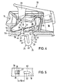
- connection or. 1 has a two-part insulating body 11 made of plastic with a base body 12 and a second component 13 which can be plugged into it and which complement one another to form a body which is essentially closed except for conductor insertion openings 14, 15 and 16.
- a number of clamping body receptacles 17 corresponding to the number of poles is provided in the insulating body 11.
- Each clamp body receptacle 17 receives a clamp body 18/19 of the same design, in the exemplary embodiment two-part.
- the part 18 of the clamping body 18/19 is in the broadest sense U-shaped, relatively inherently rigid bracket, while the part 19 is a contact spring with resilient contact legs 19 'and 19 " is.
- the bracket 18 serves as a carrier and holder of the contact spring 19.
- the resilient legs 19 'and 19 "of the contact spring 19 form screwless connecting terminals between their respective end edges and opposite surfaces of the bracket body 18.
- the connecting terminal formed by the spring leg 19' can be used with the Open the pushbutton 20 on the housing as required to remove the conductor held there.
- the clamping body 11 has at its bottom 11a two spring catch feet 22 which can be inserted into insertion openings 23 of the terminal support 21 and, after being pushed through by resilient spreading apart, hold the connecting or connecting terminal 10 on the terminal support 21.
- connection or connecting terminal described so far in its construction is known per se in a comparable embodiment.
- the designs and arrangements of additional contact parts 24 with an external plug 25 for the protective conductor contact 26 described below are new.
- the additional contact part 24 is deformed from a narrow sheet metal strip into the contour which is W-shaped in the broadest sense and which can be seen in FIG. 2.
- the plug 25 is by a substantially central, about 180 ° bending of the sheet metal strip generated. From the two legs of this bend, two, that is a total of four spring tongues 27 are bent outwards. Their edges 28 (Fig. 1) are sharp or sharpened.
- the plug 25 is intended to be inserted into a further insertion opening 29 of the terminal support 21.
- the insertion opening 29 is of the same type and size as the insertion openings 23 for the spring detent feet 22 of the insulating body 11.
- the sharp edges 28 of the plug 25 mentioned come into contact with the edges 29a when inserted into the insertion opening 29 and scrape off any paint or oxide layers here to make a perfect electrical contact to the terminal support 21. As is easy to imagine, this contact takes place automatically and at the same time when the terminal 10 is plugged onto the terminal carrier 21. If this plug-in connection is effected, the additional contact part 24 is also conductively connected to the terminal carrier 21.
- the additional contact part 24 is also a special component which is attached from the outside of the insulating body 11.
- the bottom 11b of the insulating body 11 has two wall openings 30 and 31 for receiving two connecting legs 32 and 33 of the additional contact part 24.
- the wall openings 31 and 32 are consequently attached to the side of the insulating body 11 facing the terminal support 21.
- the connecting leg 32 is slightly wavy, S-shaped following an approximately right-angled bend and forms an insertion section 34 at the end for support on the inner surface of the insulating body base 11b outside the wall opening 30.
- the second connecting leg 33 is angled so that it can reach through the other wall opening 31 with a U-shaped bent back and thus resilient spring plug section 35. The assembly takes place in such a way that first the free end section 34 of the connecting section 32 is inserted into the wall opening 30, whereupon the additional contact part is pivoted clockwise with respect to FIG. 3 until the spring plug section 35 has reached the position shown.
- the additional contact part 24 can only be held on the bottom 11b of the insulating body 11, provided that it is only ensured that an electrically conductive contact with the clamping body 18/19 takes place.
- Such contact can be achieved, for example, by a pure touch system on surfaces or edges of the clamping body 18/19 lying in the engagement area of the additional contact part.
- FIG. 3 shows a possibility of a plug connection directly with the clamping body 18/19, although the additional contact part 24 from the outside of the insulating body 11 is assembled here.
- the arrangement is such that the bent or folded spring plug section 35 is inserted into a recess 36 of the contact spring 19, which is simultaneously provided for the engagement of a bent tongue 37 of the bracket body 18.
- the other connecting leg 32 striving away from the connecting leg 33 due to resilient prestress presses with the front edge of its free end section 34 against a tongue 38 bent out of the bracket body 18.
- the additional contact part 24 is therefore directly plug-connected to the clamping body 18/19 via its connecting legs 33 and 34 , so that here the wall openings 30 and 31 essentially do not have to perform a holding function for the additional contact part 24.
- the wall openings 30 and 31 are to be provided only in the area of the protective conductor clamp body space 17 in the bottom 11b of the insulating body 11.
- these wall openings 30 and 31 can be provided at the same time or they can also be designed such that they are only formed, for example, by weakened wall zones as predetermined breaking openings, which are only pierced when the relevant terminal is equipped with the additional protective conductor contact part shall be.
- the additional contact parts 24 do not consist of bent, but punched out, flat cross-sectional and undeformed contact plates.
- the one-piece contact part 24 is divided into an anchoring section 47 and the actual plug 25 formed from sections 39 to 41.
- the leg 41 adjoining the bend 40 beyond the web 39 is resilient to the web 39 to compensate for tolerances .
- the essentially U-shaped plug 25 engages in a terminal support insertion opening 29 in accordance with the first embodiment according to FIGS. 1 and 3.
- the edge edges 46 of the web 39 and spring leg 41 are sharp (28) for penetrating a lacquer or oxide layer of the reveal 29a of the corresponding insertion opening 29.
- the plug 25 shown in FIG. 4 is also attached from the outside and inserted into a single opening 30 which is circumferentially adapted to the anchoring section 47 until shoulders 43 which limit the insertion lie in an adapted groove 44 of the insulating body 11.
- the bracket optionally takes place here by means of a clamp connection, but above all by virtue of the fact that at least one of the two anchoring legs designated 32 and 33 cooperate with legs of the contact spring 18 or 19 in a positive and / or clamping manner. In the exemplary embodiment, this takes place in that the anchoring leg 32 penetrates a clamping slot 42 of the contact spring 18 which is less than its thickness and is held therein in a clamped manner.
- the second anchoring section 33 can be held analogously in another contact spring section, it is supported here only in a positive or non-positive manner on the edge of the tongue 37 pointing to the left in FIG. 5.
- the anchoring section 32 clamps on the edge of the cutout 42.
- FIG. 6 differs essentially from that shown in FIG. 4 in that two plugs 25 are attached to the anchoring section 47 of the additional contact part 24.
- These two plugs are arranged in mirror image to one another; their webs 39 are on the outside and the tolerance-compensating resilient tongues 41 are on the inside.
- This “double plug” is preferably intended for the plug connection with a terminal carrier 21 having two (identical) insertion openings 29 ′ and 29.
- the double plug arrangement allows the protective conductor contact and the retention forces to be further improved.
- barbed latching noses 48 are formed on outwardly facing edge edges 45 of the anchoring sections 32 and 33 and on the outwardly facing webs 39 of the plugs 25, latching lugs 49 which run in opposite directions on their marginal edges 46.
- the marginal edges of the latching lugs 48 and 49 are each designed in such a way that they Do not impede the plugging process of the additional contact part 24 into the insulating body 11 or into the insertion openings on the terminal support side, but here, however, ensure a significant increase in the retention forces.
Landscapes
- Connector Housings Or Holding Contact Members (AREA)
- Connections Arranged To Contact A Plurality Of Conductors (AREA)
- Coupling Device And Connection With Printed Circuit (AREA)
- Connections Effected By Soldering, Adhesion, Or Permanent Deformation (AREA)
- Multi-Conductor Connections (AREA)
- Processing Of Terminals (AREA)
- Mechanical Coupling Of Light Guides (AREA)
- Details Of Connecting Devices For Male And Female Coupling (AREA)
Abstract
Description
Die Erfindung bezieht sich auf eine Anschluß- oder Verbindungsklemme für elektrische Geräte wie Leuchten, Herde oder Waschmaschinen mit einem Isolierkörper und darin angeordneten Leiteranschlußkontakten, von denen wenigstens einer ein Schutzleiterkontakt ist, der mit einem zusätzlichen Kontaktteil versehen ist, welcher die einem Klemmenträger zugekehrte Wandung des Isolierkörpers durchgreift und mit dem Klemmenträger kontaktierbar ist, wobei der zusätzliche Kontaktteil einen außenliegenden Kontaktabschnitt zum direkten Kontaktangriff am Klemmträger ausbildet.The invention relates to a connecting or connecting terminal for electrical devices such as lights, stoves or washing machines with an insulating body and conductor connection contacts arranged therein, at least one of which is a protective conductor contact which is provided with an additional contact part which faces the wall of a terminal carrier Grips through the insulating body and can be contacted with the terminal support, the additional contact part forming an external contact section for direct contact attack on the terminal support.
Bei solchen Anschluß- bzw. Verbindungsklemmen wird die Geräteerdung in der Regel dadurch vorgenommen, daß an den Pol der Klemme, an den der Schutzleiter des Netzanschlußkabels anzuklemmen ist, ein besonderes Kabel angeschlossen wird, das mit seinem anderen Ende an elektrisch leitenden Teilen des Geräts befestigt, insbesondere angeschraubt wird. Dies ist umständlich.In such connection or connection terminals, the device is grounded in that a special cable is connected to the pole of the terminal to which the protective conductor of the power cord is to be connected, which is attached at its other end to electrically conductive parts of the device , especially screwed. This is cumbersome.
Aus dem DE-U-76 13 429 ist eine elektrische Reihenklemme für Schaltanlagen bekannt, bei der in einer zu den Leiterklemmkörpern versetzten Ebene ein Schutzleiterklemmkörper angeordnet ist. Die Schutzleiterebene ist im wesentlichen in der Ebene des als Tragschiene ausgebildeten Klemmenträgers angeordnet. Die Tragschiene dient zugleich als Schutzleiterschiene, und der Schutzleiterklemmkörper ist galvanisch mit der Tragschiene verbindbar. Dies geschieht durch eine besondere mit gesonderter Schraube zu betätigende Klemmvorrichtung. Diese Klemmvorrichtung ist relativ aufwendig, vor allem erschwert sie die Montage und Demontage der Klemme wie auch die Herstellung des Schutzleiterkontaktes durch zusätzliche Handhabungen.From DE-U-76 13 429 an electrical terminal block for switchgear is known, in which a protective conductor clamping element is arranged in a plane offset from the conductor clamping elements. The protective conductor level is essentially arranged in the level of the terminal support designed as a mounting rail. The mounting rail also serves as a protective conductor rail and the protective conductor clamp can be galvanically connected to the mounting rail. This is done by a special clamping device to be operated with a separate screw. This clamping device is relatively complex, above all it complicates the assembly and disassembly of the clamp as well as the production of the protective conductor contact by additional manipulations.
Eine Anschluß- oder Verbindungsklemme gemäß dem Oberbegriff des Anspruches 1 ist aus US-A-417186 bekannt.A connection or connection terminal according to the preamble of claim 1 is known from US-A-417186.
Der Erfindung leigt im wesentlichen die Aufgabe zugrunde, eine Anschluß- oder Verbindungsklemme der im Oberbegriff des Patentanspruches 1 angegebenen Art verfügbar zu machen, die so ausgebildet ist, daß die Erdung bzw. Schutzkontaktierung wie auch die Montage oder Demontage der Klemme selbst erleichtert werden.The invention is essentially based on the object to make a connection or connection terminal of the type specified in the preamble of claim 1 available, which is designed so that the grounding or protective contact as well as the assembly or disassembly of the terminal itself are facilitated.
Die Erfindung löst diese Aufgabe dadurch, daß der zusätzliche Kontaktabschnitt als in eine Einstecköffnung des Klemmenträgers einsteckbarer Stecker ausgebildet ist, der von der Außenseite des Isolierkörpers her über Verbindungsschenkel form- und/oder klemmschlüssig mit Isolierkörper und/oder mit dem Schutzleiterkontakt steckverbunden ist.The invention solves this problem in that the additional contact section is designed as a plug which can be plugged into an insertion opening of the terminal carrier and which is plug-in from the outside of the insulating body via connecting legs in a form-fitting and / or clamping manner with the insulating body and / or with the protective conductor contact.
Aufgrund dieser Ausgestaltung ist es lediglich erforderlich, im Klemmenträger die Einstecköffnung zur Kontaktierung des Kontaktteils vorzusehen. Weitere Maßnahmen, insbesondere solche befestigungstechnischer Natur, wie Schrauben od.dgl., gelangen in Fortfall. Es genügt, die Anschluß- bzw. Verbindungsklemme auf den Klemmenträger aufzusetzen, wodurch die Schutzleiterkontaktierung selbstätig bewerkstelligt ist; sodann ist die Klemme in gewohnter Weise zu befestigen.Because of this configuration, it is only necessary to provide the insertion opening for contacting the contact part in the terminal support. Further measures, in particular those of a fastening technology nature, such as screws or the like, are discontinued. It is sufficient to place the connecting or connecting terminal on the terminal carrier, as a result of which the protective conductor contact is carried out automatically; then the clamp is to be fastened in the usual way.
Um eine besonders sichere Kontaktierung zu gewährleisten, ist der Stecker vorteilhaft mit scharfen Kanten zum Durchdringen einer den Klemmenträger überziehenden Isolierschicht versehen, so daß es entbehrlich ist, den Klemmenträger etwa durch Abschaben des Lackes für eine sichere Kontaktierung vorzubereiten. Die scharfen Kanten des Steckers können auch an auswärts strebenden Federzungen angeordnet sein, wodurch zugleich eine toleranzausgleichende Anpassung des Steckers an die Einstecköffnung auf einfache Weise sichergestellt ist.In order to ensure particularly reliable contacting, the plug is advantageously provided with sharp edges for penetrating an insulating layer covering the terminal support, so that it is unnecessary to prepare the terminal support for safe contacting, for example by scraping off the paint. The sharp edges of the plug can also be arranged on spring tongues striving outwards, whereby at the same time a tolerance-compensating adaptation of the plug to the insertion opening is ensured in a simple manner.
Ein besonderer Vorteil der Erfindung besteht darin, daß der Stecker ein gesondertes Bauteil ist, das, mindestens eine Wandausnehmung des Isolierkörpers durchgreifend, in Kontaktanlage zum Schutzleiterkontakt an diesen ansteckbar bzw. angesteckt ist. Diese Lösung bietet im wesentlichen den Vorteil, daß der Erdungskontakt als solcher identisch sein kann mit einem Kontakt, wie er für stromführende Leiter bestimmt ist. Man benötigt also keinen besonders ausgestalteten Kontaktkörper, sondern kann diesbezüglich auf herkömmliche Bauteile zurückgreifen.A particular advantage of the invention is that the plug is a separate component which, penetrating at least one wall recess in the insulating body, can be plugged or plugged into it in contact with the protective conductor contact. This solution essentially offers the advantage that the ground contact as such can be identical to a contact as it is intended for live conductors. So you do not need a specially designed contact body, but can use conventional components in this regard.
Im Zusammenhang mit dem letztgenannten Merkmal besteht eine noch weitere Verbesserung darin, daß der Stecker von der Außenseite des Isolierkörpers her mit dem Schutzleiterkontakt verbindbar ist. Dies hat insbesondere den Vorteil, daß eine Klemme jederzeit auch nachträglich mit dem erfindungsgemäßen Schutzleiterkontakt-Stecker ausgerüstet werden kann, selbst wenn dies zunächst bei der Herstellung oder der Anwendung der Klemme nicht vorgesehen war. Es braucht lediglich die Wandausnehmung des Isolierkörpers vorbereitend vorgesehen oder nachträglich, z.B. mittels Durchstoßung, angebracht und der zusätzliche Kontaktteil eingesetzt zu werden.In connection with the latter feature, there is still a further improvement in that the plug can be connected to the protective conductor contact from the outside of the insulating body. This has the particular advantage that a terminal can also be retrofitted with the protective conductor contact plug according to the invention at any time, even if this was not initially provided for in the manufacture or use of the terminal. Only the wall recess of the insulating body needs to be provided in advance or subsequently, e.g. by means of piercing, and the additional contact part to be inserted.
Dadurch, daß der Stecker über Verbindungsschenkel form- bzw. klemmschlüssig mit dem Isolierkörper und/oder mit dem Schutzleiterkontakt steckverbunden ist, ist eine einfache, jederzeit vorzunehmende Steckmontage des Steckers an die Klemme bzw. an den Schutzleiterkontakt möglich. Wichtig ist, daß mindestens einer der in den Klemmkörperraum eintretenden Verbindungsschenkel in sichere galvanische Verbindung mit dem Schutzleiterkontakt tritt.The fact that the plug is plug-and-socket with the insulating body and / or with the protective conductor contact by means of a connecting leg, makes it easy to plug the plug into the terminal or the protective conductor contact at any time. It is important that at least one of the connecting legs entering the clamping body space comes into a safe galvanic connection with the protective conductor contact.
Es ist im Rahmen der Erfindung möglich, den Stecker unmittelbar mit dem Schutzleiterkontakt zu verbinden, und zwar auch dann, wenn der Stecker nachträglich von der Außenseite der Klemme montiert wird. Dies wird z.B. dadurch erreicht, daß mindestens einer der Verbindungsschenkel in einer Ausnehmung des Schutzleiterkontaktes formschlüssig eingeklemmt gehalten ist.It is possible within the scope of the invention to connect the plug directly to the protective conductor contact, even if the plug is subsequently mounted from the outside of the terminal. This is done, for example achieved that at least one of the connecting legs is held in a form-fitting manner in a recess of the protective conductor contact.
Vorteilhafte weitere Ausgestaltungen und zweckmäßige Weiterbildungen des Erfindungsgegenstandes ergeben sich aus den sonstigen, weiter unten erläuterten Merkmalen der Unteransprüche.Advantageous further refinements and expedient further developments of the subject matter of the invention result from the other features of the subclaims explained below.
Die Erfindung ermöglicht in einfacher Weise die Ausbildung einer Anschluß- oder Verbindungsklemme, die automatisch die Schutzleiterverbindung herstellt, sobald die Klemme am Klemmenträger befestigt wird. Um dies zu erreichen, kann die Klemme entweder bereits bei ihrer Herstellung mit dem Stecker ausgerüstet werden oder - in besonders vorteilhafter Weise - es kann der Schutzleiter-Stecker nachträglich an der Klemme angebracht werden, ohne diese demontieren zu müssen.The invention enables a connection or connecting terminal to be formed in a simple manner, which automatically establishes the protective conductor connection as soon as the terminal is attached to the terminal carrier. To achieve this, the terminal can either be equipped with the plug during its manufacture or - in a particularly advantageous manner - the protective conductor plug can be retrofitted to the terminal without having to disassemble it.
Die Erfindung ist nachfolgend anhand mehrerer in der Zeichnung dargestellten besonders vorteilhaft erscheinenden Ausführungsbeispiele näher erläutert. In den Zeichnungen zeigen:
- Fig. 1 eine Ansicht einer dreipoligen Anschluß- bzw. Verbindungsklemme,
- Fig. 2 die Aufsicht auf einen blechförmigen Klemmenträger mit den zur Befestigung und zur Schutzleiterkontaktierung vorgesehenen Einstecköffnungen,
- Fig. 3 einen Querschnitt durch eine Klemme im Bereich eines Schutzleiterkontaktes etwa nach der Schnittlinie III-III in Fig. 1,
- Fig. 4 eine der Fig. 3 entsprechende Schnittdarstellung einer zweiten Ausführung,
- Fig. 5 eine schematische Detailansicht in Richtung des Ansichtspfeiles V in Fig. 4,
- Fig. 6 eine dritte Ausführungsform in der Darstellung entsprechend den Fig. 3 und 4 und
- Fig. 7 eine Aufsicht auf einen für die Ausführung entsprechend Fig. 6 besonders vorteilhaften blechförmigen Klemmenträger.
- 1 is a view of a three-pole terminal or connecting terminal,
- 2 shows the top view of a sheet-metal terminal support with the insertion openings provided for fastening and for contacting the protective conductor,
- 3 shows a cross section through a terminal in the area of a protective conductor contact approximately along the section line III-III in FIG. 1,
- 4 is a sectional view corresponding to FIG. 3 of a second embodiment,
- 5 shows a schematic detailed view in the direction of the arrow V in FIG. 4,
- Fig. 6 shows a third embodiment in the representation corresponding to Figs. 3 and 4 and
- FIG. 7 is a plan view of a sheet-like clamp carrier which is particularly advantageous for the embodiment according to FIG. 6.
Die insgesamt mit 10 bezeichnete Anschluß-bzw. Verbindungsklemme nach Fig. 1 weist einen zweiteiligen Isolierkörper 11 aus Kunststoff mit Grundkörper 12 und ein damit steckverrastbares zweites Bauteil 13 auf, die einander zu einem bis auf Leitereinstecköffnungen 14, 15 und 16 im wesentlichen geschlossenen Körper ergänzen. Im Isolierkörper 11 ist eine der Polzahl entsprechende Anzahl von Klemmkörperaufnahmen 17 vorgesehen. Jede Klemmkörperaufnahme 17 nimmt einen jeweils gleich ausgebildeten, beim Ausführungsbeispiel zweiteiligen Klemmkörper 18/19 auf. Das Teil 18 des Klemmkörpers 18/19 ist ein im weitesten Sinne U-förmig gestalteter, relativ eigensteifer Bügel, während das Teil 19 eine Kontaktfeder mit federnden Kontaktschenkeln 19' und 19" ist. Der Bügel 18 dient als Träger und Halter der Kontaktfeder 19. Die federnden Schenkel 19' und 19" der Kontaktfeder 19 bilden zwischen ihren jeweiligen Stirnkanten und gegenüberliegenden Flächen des Bügelkörpers 18 schraubenlose Anschlußklemmen aus. Die vom Federschenkel 19' gebildete Anschlußklemme läßt sich mit Hilfe der gehäuseseitigen Drucktaste 20 nach Belieben wieder öffnen, um den dort gehaltenen Leiter wieder zu entfernen.The connection or. 1 has a two-
Zur steckbaren Befestigung an einem Klemmenträger 21 weist der Klemmkörper 11 an seinem Boden 11a zwei Federrastfüße 22 auf, die in Einstecköffnungen 23 des Klemmenträgers 21 einsteckbar sind und nach dem Durchstecken durch rückfederndes Aufspreizen die Anschluß- bzw. Verbindungsklemme 10 am Klemmenträger 21 festhalten.For pluggable attachment to a
Die in ihrem Aufbau bisher beschriebene Anschluß- bzw. Verbindungsklemme ist an sich in vergleichbarer Ausführung bekannt. Neu hingegen sind die nachfolgend beschriebenen Gestaltungen und Anordnungen zusätzlicher Kontaktteile 24 mit einem außenliegenden Stecker 25 für den Schutzleiterkontakt 26.The connection or connecting terminal described so far in its construction is known per se in a comparable embodiment. On the other hand, the designs and arrangements of
Beim Ausführungsbeispiel nach Fig. 3 ist der zusätzliche Kontaktteil 24 aus einem schmalen Blechstreifen in die in Fig. 2 ersichtliche, im weitesten Sinne W-förmige Kontur verformt. Der Stecker 25 wird durch eine im wesentlichen zentrale, etwa 180° betragende Umbiegung des Blechstreifens erzeugt. Aus den beiden Schenkeln dieser Umbiegung sind jeweils zwei, insgesamt also vier Federzungen 27 nach auswärts gebogen. Ihre Kanten 28 (Fig. 1) sind scharf bzw. angeschärft.In the exemplary embodiment according to FIG. 3, the
Der Stecker 25 ist dazu bestimmt, in eine weitere Einstecköffnung 29 des Klemmenträgers 21 eingesteckt zu werden. Beim Ausführungsbeispiel ist die Einstecköffnung 29 von gleicher Art und Größe wie die Einstecköffnungen 23 für die Federrastfüße 22 des Isolierkörpers 11. Die erwähnten scharfen Kanten 28 des Steckers 25 kontaktieren beim Einstecken in die Einstecköffnung 29 deren Berandung 29a und schaben hier eventuelle Lack-oder Oxydschichten ab, um einen einwandfreien elektrischen Kontakt zum Klemmenträger 21 herzustellen. Wie leicht vorstellbar, vollzieht sich dieser Kontakt automatisch und zugleich mit dem Aufstecken der Klemme 10 auf den Klemmenträger 21. Ist diese Steckverbindung bewirkt, ist auch das zusätzliche Kontaktteil 24 leitend mit dem Klemmenträger 21 verbunden.The
Bei diesem ersten Ausführungsbeispiel ist weiterhin der zusätzliche Kontaktteil 24 ein besonderes Bauteil, das von der Außenseite des Isolierkörpers 11 her angebracht wird. Hierzu besitzt der Boden 11b des Isolierkörpers 11 zwei Wanddurchbrüche 30 und 31 zur Aufnahme zweier Verbindungsschenkel 32 und 33 des zusätzlichen Kontaktteils 24. Die Wanddurchbrüche 31 und 32 sind folglich an der dem Klemmenträger 21 zugewandten Seite des Isolierkörpers 11 angebracht.In this first exemplary embodiment, the
Der Verbindungsschenkel 32 ist im Anschluß an eine etwa rechtwinklige Umbiegung leicht wellenartig, S-förmig gestaltet und bildet endseits einen Einsteckabschnitt 34 zur Abstützung auf der inneren Fläche des Isolierkörper-Bodens 11b außerhalb des Wanddurchbruchs 30. Der zweite Verbindungsschenkel 33 ist so abgewinkelt, daß er mit einem U-förmig zurückgebogenen und dadurch federbaren Federsteckabschnitt 35 den anderen Wanddurchbruch 31 durchgreifen kann. Die Montage erfolgt so, daß zunächst der freie Endabschnitt 34 des Verbindungsabschnitts 32 in den Wanddurchbruch 30 eingeführt wird, woraufhin das zusätzliche Kontaktteil im Uhrzeigersinn bezüglich Fig. 3 so weit verschwenkt wird, bis der Federsteckabschnitt 35 die dargestellte Lage erreicht hat. In dieser Position kann der zusätzliche Kontaktteil 24 lediglich am Boden 11b des Isolierkörpers 11 gehalten sein, sofern nur gewährleistet ist, daß ein elektrisch leitender Kontakt mit dem Klemmkörper 18/19 erfolgt. Ein solcher Kontakt kann etwa durch reine Berührungsanlage an im Eingriffsbereich des zusätzlichen Kontaktteils liegenden Flächen oder Kanten des Klemmkörpers 18/19 bewerkstelligt sein.The connecting
Das Ausführungsbeispiel nach Fig. 3 zeigt eine Möglichkeit einer Steckverbindung unmittelbar mit dem Klemmkörper 18/19, obgleich der zusätzliche Kontaktteil 24 von der Außenseite des Isolierkörpers 11 her montiert wird. Hierbei ist die Anordnung so getroffen, daß der umgebogene bzw. gefaltete Federsteckabschnitt 35 in einer Ausnehmung 36 der Kontaktfeder 19 einsteckt, die gleichzeitig für den Eingriff einer hochgebogenen Zunge 37 des Bügelkörpers 18 vorgesehen ist. Der aufgrund federnder Vorspannung vom Verbindungsschenkel 33 wegstrebende andere Verbindungsschenkel 32 drückt mit der Stirnkante seines freien Endabschnitts 34 gegen eine aus dem Bügelkörper 18 herausgebogene Zunge 38. Der zusätzliche Kontaktteil 24 ist also über seine Verbindungsschenkel 33 und 34 mit dem Klemmkörper 18/19 selbst direkt steckverbunden, so daß hier die Wanddurchbrüche 30 und 31 im wesentlichen keine haltende Funktion für den zusätzlichen Kontaktteil 24 auszuüben brauchen.The embodiment according to FIG. 3 shows a possibility of a plug connection directly with the clamping
Will man bei einer Anschluß- bzw. Verbindungsklemme bekannter Art eine Klemmkörperanordnung 18/19 mit dem zusätzlichen Schutzleiterkontaktteil 24 ausrüsten, sind lediglich im Bereich des Schutzleiter-Klemmkörperraumes 17 im Boden 11b des Isolierkörpers 11 die Wanddurchbrüche 30 und 31 anzubringen. Bei neu zu konzipierenden Isolierkörpern kann man diese Wanddurchbrüche 30 und 31 gleich mit vorsehen oder sie auch so ausgestalten, daß sie lediglich z.B. durch geschwächte Wandzonen als Sollbruchöffnungen ausgebildet sind, die erst dann durchstoßen werden, wenn die betreffende Klemme mit dem zusätzlichen Schutzleiter-Kontaktteil ausgerüstet werden soll.If you want to equip a
Die genannten und weitere Vorteile besitzen auch die in den Fig. 4 und 6 dargestellten Ausführungsbeispiele. Sofern dortige Anordnungen und Ausgestaltungen mit derjenigen nach Fig. 3 gleich oder identisch sind, wird auf eine nochmalige Beschreibung verzichtet. Gleiche oder gleichwirkende Teile sind entsprechend numeriert.The mentioned and further advantages also have the exemplary embodiments shown in FIGS. 4 and 6. Insofar as the arrangements and configurations there are identical or identical to those according to FIG. 3, there is no further description. The same or equivalent parts are numbered accordingly.
Bei den Ausführungsbeispielen der Fig. 4 und 6 bestehen die zusätzlichen Kontaktteile 24 nicht aus biegeverformten, sondern ausgestanzten, flachquerschnittigen sowie unverformten Kontaktblechen. Bei der Ausführung nach Fig. 4 gliedert sich der einstückige Kontaktteil 24 in einen Verankerungsabschnitt 47 und den aus den Abschnitten 39 bis 41 gebildeten eigentlichen Stecker 25. Der jenseits des Steges 39 an die Umbiegung 40 anschließende Schenkel 41 ist gegenüber dem Steg 39 toleranzausgleichend-federbar. Der im wesentlichen U-förmige Stecker 25 greift entsprechend der ersten Ausführungsform nach den Fig. 1 und 3 in eine Klemmenträger-Einstecköffnung 29 ein. Die Randkanten 46 vom Steg 39 und Federschenkel 41 sind scharf (28) zum Durchdringen einer Lack-oder Oxydschicht der Laibung 29a der entsprechenden Einstecköffnung 29.In the exemplary embodiments in FIGS. 4 and 6, the
Auch der in Fig. 4 dargestellte Stecker 25 wird von außen angebracht und in eine einzige, dem Verankerungsabschnitt 47 umfänglich angepaßte Durchbrechung 30 eingeschoben, bis einschubbegrenzende Schultern 43 in einer angepaßten Nut 44 des Isolierkörpers 11 einliegen. Die Halterung erfolgt ggf. hier durch Klemmschluß, vor allem aber dadurch, daß wenigstens einer der beiden mit 32 und 33 bezeichneten Verankerungsschenkel form-und/oder klemmschlüssig mit Schenkeln der Kontaktfeder 18 oder 19 zusammenwirken. Beim Ausführungsbeispiel erfolgt dies dadurch, daß der Verankerungsschenkel 32 einen seine Dicke unterschreitenden Klemmschlitz 42 der Kontaktfeder 18 durchdringt und hierin klemmschlüssig gehalten ist. Der zweite Verankerungsabschnitt 33 kann zwar analog in einem anderen Kontaktfeder-Abschnitt gehalten sein, stützt sich jedoch hier nur an dem in Fig. 5 nach links weisenden Rand der Zunge 37 form- bzw. kraftschlüssig ab. In dem mit 50 bezeichneten Abstand klemmt andererseits der Verankerungsabschnitt 32 am Rand des Ausschnitts 42.The
Das Ausführungsbeispiel nach Fig. 6 unterscheidet sich im wesentlichen von dem in Fig. 4 dargestellten dadurch, daß an dem Verankerungsabschnitt 47 des zusätzlichen Kontaktteiles 24 zwei Stecker 25 angebracht sind. Diese beiden Stecker, von denen jeder im wesentlichen die Konfiguration des Steckers 25 nach Fig. 4 aufweist, sind spiegelbildlich zueinander angeordnet; ihre Stege 39 liegen dabei außen und die toleranzausgleichend-federnden Zungen 41 innen. Dieser "Doppelstecker" ist vorzugsweise zur Steckverbindung mit einem zwei (gleiche) Einstecköffnungen 29' und 29" aufweisenden Klemmenträger 21 bestimmt. Durch die doppelte Steckeranordnung können die Schutzleiter-Kontaktgabe und die Rückhaltekräfte noch weiter verbessert werden.The embodiment of FIG. 6 differs essentially from that shown in FIG. 4 in that two
Fig. 6 zeigt außerdem Möglichkeiten, die Auszugskräfte sowohl des zusätzlichen Kontaktteils 24 aus dem Isolierkörper 11 als auch der Stecker 25 aus den klemmenträgerseitigen Einstecköffnungen 29 zu erhöhen. Zu diesem Zweck sind einerseits im Bereich des Verankerungsabschnittes 47 an nach außen weisenden Randkanten 45 der Verankerungsabschnitte 32 und 33 widerhakenartige Rastnasen 48 und an den nach außen weisenden Stegen 39 der Stecker 25 an deren Randkanten 46 konträr verlaufende Rastnasen 49 ausgebildet. Ersichtlich sind die Randkanten der Rastnasen 48 und 49 jeweils so ausgebildet, daß sie den Ein-bzw. Ansteckvorgang des zusätzlichen Kontaktteiles 24 in den Isolierkörper 11 bzw. in die klemmenträgerseitigen Einstecköffnungen nicht behindern, wohl aber hier für eine deutliche Steigerung der Rückhaltekräfte sorgen.6 also shows options for increasing the pull-out forces of both the
Die beim Ausführungsbeispiel nach Fig. 6 beschriebene Anordnung und Ausbildung von Rastnasen 48 und/oder 49 kann selbstverständlich auch bei dem Ausführungsbeispiel nach Fig. 4 zur Anwendung kommen.The arrangement and design of locking lugs 48 and / or 49 described in the embodiment according to FIG. 6 can of course also be used in the embodiment according to FIG. 4.
Claims (14)
- A connector for electrical devices such as lights, hearths or washing machines comprising an insulating element (11) and conductor connection contacts arranged therein, at least one of said conductor connection contacts being a protective conductor contact (26) provided with an additional contact part (25), which engages through the wall of the insulating element (11) facing a connector support (21) and can be contacted with said connector support (21), the additional contact part (25) forming an outlying contact section for direct contact engagement on the connector support (21), characterised in that the additional contact section is designed as a plug (25), which is insertable in a plug opening (29) in the connector support (21) and forms a positive and/or clamping locking with the insulating element (11) from the outside of the insulating element (11) via connecting limbs (32, 33) and/or forms a plug-type connection with the protective conductor contact (26).
- A connector according to claim 1, characterised in that the plug (25) is provided with sharp edges (28) for penetrating an insulating layer covering the connector support (21).
- A connector according to claim 2, characterised in that the sharp edges (28) are arranged on outwardly pointing resilient tongues (27).
- A connector according to claim 1, characterised in that one of the connecting limbs (32) comprises an angled suspension section (34) for engaging laterally behind a wall opening (30) and a bent spring plug section (35) for automatic clamping in a second wall opening (31).
- A connector according to claim 1, characterised in that one of the connecting limbs (33) is held clamped in a positive-locking manner in a recess (37) in the protective conductor contact (19; 26), whilst the second connecting limb (32) is pressure-locked against a protective conductor contact abutment (38) under the action of a - preferably inherent - expanding spring force.
- A connector according to one of claims 1 to 5, characterised in that the additional contact part (24) is bent in one piece from a sheet metal strip.
- A connector according to one of claims 1 to 5, characterised in that the additional contact part (24) is merely stamped in one piece from a sheet metal strip having a flat cross section.
- A connector according to claim 7, characterised in that the plug (25) of the additional contact part (24) is formed by a web (39) emerging substantially vertically from the insulating element (11) and an opposite resilient tongue (41) adjoining the web (39) via a curved section (40).
- A connector according to claim 8, characterised in that the additional contact part (24) is provided with two plugs (25) of this type.
- A connector according to claim 9, characterised in that a special plug opening (29', 29") is provided in the connector support for each of the two plugs (25).
- A connector according to claim 9 or 10, characterised in that the resilient tongues (41) of the plugs (25) are arranged pointing inwards towards one another and the webs (39) are arranged on the outside on the additional contact part (24).
- A connector according to claim 1, characterised in that at least one of the connecting limbs (32 or 33) of the additional contact part (24) can be inserted in a force or positive-locking manner in a clamping slot (36 or 42) in a limb (19 or 18) of the connector element (18/19).
- A connector according to one of claims 7 to 12, characterised in that the additional contact part (24) is provided with at least one shoulder (43) engaging in a base-side adapted receiving groove (44) in the insulating element (11) for centring and limiting the insertion.
- A connector according to one of claims 7 to 13, characterised in that the additional contact part (24) is provided on edges (45, 46) of its anchoring section (47) and/or of its plug (25) with punched-out barb-like locking noses (48, 49) for anchoring on the insulating element (11) and/or in the connector support (21).
Priority Applications (1)
| Application Number | Priority Date | Filing Date | Title |
|---|---|---|---|
| AT86110254T ATE82434T1 (en) | 1985-08-13 | 1986-07-25 | CONNECTION OR CONNECTION CLAMP FOR ELECTRICAL DEVICES. |
Applications Claiming Priority (4)
| Application Number | Priority Date | Filing Date | Title |
|---|---|---|---|
| DE3528980 | 1985-08-13 | ||
| DE3528980 | 1985-08-13 | ||
| DE3621369 | 1986-06-26 | ||
| DE19863621369 DE3621369A1 (en) | 1985-08-13 | 1986-06-26 | CONNECTION OR CONNECTING TERMINAL FOR ELECTRICAL DEVICES |
Publications (3)
| Publication Number | Publication Date |
|---|---|
| EP0212330A2 EP0212330A2 (en) | 1987-03-04 |
| EP0212330A3 EP0212330A3 (en) | 1988-10-26 |
| EP0212330B1 true EP0212330B1 (en) | 1992-11-11 |
Family
ID=25835007
Family Applications (1)
| Application Number | Title | Priority Date | Filing Date |
|---|---|---|---|
| EP86110254A Expired - Lifetime EP0212330B1 (en) | 1985-08-13 | 1986-07-25 | Terminal clamp or splicing ear for electrical apparatus |
Country Status (7)
| Country | Link |
|---|---|
| US (1) | US4728295A (en) |
| EP (1) | EP0212330B1 (en) |
| AT (1) | ATE82434T1 (en) |
| AU (1) | AU593469B2 (en) |
| DE (2) | DE3621369A1 (en) |
| ES (1) | ES2000581A6 (en) |
| NO (1) | NO169516C (en) |
Cited By (3)
| Publication number | Priority date | Publication date | Assignee | Title |
|---|---|---|---|---|
| DE19949387A1 (en) * | 1999-10-13 | 2001-05-31 | Electro Terminal Gmbh | Connection terminal has insulating body in which contact element is mounted, and contact part inserted in mounting hole from inside, secured against inward movement by contact element |
| CN101776491B (en) * | 2003-10-10 | 2011-12-14 | 罗斯蒙德公司 | Compact process transmitter |
| DE19964616B4 (en) * | 1999-10-13 | 2012-12-20 | Adels-Contact Elektrotechnische Fabrik Gmbh & Co. Kg | Connection terminal has insulating body in which contact element is mounted, and contact part inserted in mounting hole from inside, secured against inward movement by contact element |
Families Citing this family (27)
| Publication number | Priority date | Publication date | Assignee | Title |
|---|---|---|---|---|
| DE3621369A1 (en) * | 1985-08-13 | 1987-02-19 | Broekelmann Jaeger & Busse | CONNECTION OR CONNECTING TERMINAL FOR ELECTRICAL DEVICES |
| DE3743409C2 (en) * | 1987-12-21 | 1994-10-06 | Electro Terminal Gmbh | Screwless connection clamp |
| DE8801623U1 (en) * | 1988-02-09 | 1988-04-07 | Brökelmann, Jaeger & Busse GmbH & Co, 5760 Arnsberg | Connection terminal for electrical devices |
| NL8901467A (en) * | 1989-06-08 | 1991-01-02 | Du Pont Nederland | CONNECTOR. |
| DE4034789C1 (en) * | 1990-11-02 | 1992-04-16 | C.A. Weidmueller Gmbh & Co, 4930 Detmold, De | |
| DE9104298U1 (en) * | 1991-04-09 | 1991-07-18 | Zumtobel Ag, Dornbirn | Grounding part |
| DE4344132C2 (en) * | 1993-12-23 | 1996-12-12 | Broekelmann Jaeger & Busse | PCB terminal |
| DE19604918A1 (en) * | 1996-02-01 | 1997-08-07 | Wago Verwaltungs Gmbh | Electrical terminal with non-fused earth conductor plug contact e.g. for circuit board |
| US5664965A (en) * | 1996-03-29 | 1997-09-09 | Berg Technology, Inc. | Device for fixing an electrical connector to a printed circuit board |
| FR2756423B1 (en) * | 1996-11-22 | 1999-02-12 | Applic Electro Mecaniques | CONNECTING ELEMENT OF AN ELECTRIC CONDUCTOR WITH A CHASSIS SHEET, AND CONNECTING DEVICE COMPRISING SUCH AN ELEMENT |
| DE19710306C2 (en) * | 1997-02-26 | 2001-12-06 | Wago Verwaltungs Gmbh | Electrical clamp |
| ES2159247B1 (en) * | 1999-08-13 | 2002-04-01 | Tecnica De Conexiones S A | TERMINAL WITH INTEGRATED LAND CONTACT FOR LUMINAIRES. |
| DE10039963C2 (en) * | 2000-08-16 | 2003-01-02 | Siemens Ag | Piercing means |
| DE10053300A1 (en) * | 2000-10-27 | 2002-05-16 | Wieland Electric Gmbh | terminal connector |
| DE10218507C1 (en) * | 2002-04-25 | 2003-05-15 | Electro Terminal Gmbh Innsbruc | Contact and/or connection terminal has supporting element pivotably mounted/deformably positioned, spring biased against spring arm, manually operable to relieve/open clamping point |
| DE20305228U1 (en) | 2003-04-01 | 2003-06-05 | Electro-Terminal Ges. M.B.H. & Co. Kg, Innsbruck | Clamp for connecting electrically-conducting contact bodies with at least one wire has insulating housing and pushbuttons mounted on flexible arms to release clamps when depressed |
| DE102005049798A1 (en) * | 2005-10-14 | 2007-04-26 | Phoenix Contact Gmbh & Co. Kg | Electrical terminal for printed circuit boards |
| DE102007051900B4 (en) * | 2007-10-29 | 2009-09-10 | Wago Verwaltungsgesellschaft Mbh | Spring connection |
| DE202008010347U1 (en) | 2008-08-04 | 2008-10-02 | Wago Verwaltungsgesellschaft Mbh | Plug-in PE protective contact |
| DE102010014143B4 (en) * | 2010-04-07 | 2016-07-07 | Wago Verwaltungsgesellschaft Mbh | Actuation device for an electrical connection terminal |
| EP2656445B1 (en) | 2010-12-21 | 2019-03-20 | Tridonic GmbH & Co. KG | Connection terminal or connecting terminal for electrical conductors |
| AT13901U1 (en) | 2013-03-21 | 2014-11-15 | Tridonic Connection Technology Gmbh & Co Kg | Connection or connection terminal for electrical conductors, as well as luminaire |
| DE102015119478A1 (en) * | 2015-11-11 | 2017-05-11 | Phoenix Contact Gmbh & Co. Kg | Electrical connection terminal |
| DE202017106710U1 (en) * | 2017-11-07 | 2019-02-08 | Unger Kabel-Konfektionstechnik GmbH | Device connection terminal for a household appliance and household appliance |
| DE202018101728U1 (en) * | 2018-03-28 | 2019-07-01 | Wago Verwaltungsgesellschaft Mbh | Conductor connection terminal, clamping spring of a conductor connection terminal and terminal block |
| DE102021110425A1 (en) | 2021-04-23 | 2022-10-27 | WAGO Verwaltungsgesellschaft mit beschränkter Haftung | Conductor terminal and socket insert |
| DE102021110424A1 (en) * | 2021-04-23 | 2022-10-27 | WAGO Verwaltungsgesellschaft mit beschränkter Haftung | conductor terminal |
Family Cites Families (13)
| Publication number | Priority date | Publication date | Assignee | Title |
|---|---|---|---|---|
| DE1047273B (en) * | 1956-11-19 | 1958-12-24 | Telefunken Gmbh | Holding a bobbin in a shielding can and the shielding can on a mounting plate provided with a printed circuit |
| US3031635A (en) * | 1957-06-20 | 1962-04-24 | Ind Electronic Hardware Corp | Socket for radio tubes or the like |
| US3017596A (en) * | 1958-08-18 | 1962-01-16 | United Carr Fastener Corp | Tube shield and ground strap structure |
| US3072880A (en) * | 1959-08-05 | 1963-01-08 | Malco Mfg Co | Snap-in terminal for panel |
| DE1213507B (en) * | 1963-03-21 | 1966-03-31 | Walter Holzer | Detachable mechanical and electrical connection of components |
| NL6605676A (en) * | 1966-04-28 | 1967-10-30 | ||
| DE7613429U1 (en) * | 1976-04-28 | 1976-12-02 | Phoenix Elektrizitaetsgesellschaft H. Knuemann & Co., 4933 Blomberg | Electrical terminal block |
| FR2393448A1 (en) * | 1976-08-18 | 1978-12-29 | Wago Kontakttechnik Gmbh | ELECTRICAL CONNECTION OR CONNECTION DEVICE |
| US4363529A (en) * | 1980-07-25 | 1982-12-14 | Amp Incorporated | Terminal having improved mounting means |
| DE3032353A1 (en) * | 1980-08-28 | 1982-03-25 | Rafi Gmbh & Co Elektrotechnische Spezialfabrik, 7981 Berg | DEVICE FOR HOLDING COMPONENTS ON A PCB |
| US4353609A (en) * | 1980-10-02 | 1982-10-12 | Henes Products Corp. | Terminal for printed circuit boards |
| US4372634A (en) * | 1981-03-04 | 1983-02-08 | Amp Incorporated | Tilt latch zero insertion force connector assembly |
| DE3621369A1 (en) * | 1985-08-13 | 1987-02-19 | Broekelmann Jaeger & Busse | CONNECTION OR CONNECTING TERMINAL FOR ELECTRICAL DEVICES |
-
1986
- 1986-06-26 DE DE19863621369 patent/DE3621369A1/en not_active Withdrawn
- 1986-07-24 NO NO862979A patent/NO169516C/en not_active IP Right Cessation
- 1986-07-25 AT AT86110254T patent/ATE82434T1/en not_active IP Right Cessation
- 1986-07-25 DE DE8686110254T patent/DE3687095D1/en not_active Expired - Lifetime
- 1986-07-25 EP EP86110254A patent/EP0212330B1/en not_active Expired - Lifetime
- 1986-07-30 ES ES8600733A patent/ES2000581A6/en not_active Expired
- 1986-08-08 AU AU60999/86A patent/AU593469B2/en not_active Expired
- 1986-08-12 US US06/895,834 patent/US4728295A/en not_active Expired - Lifetime
Cited By (4)
| Publication number | Priority date | Publication date | Assignee | Title |
|---|---|---|---|---|
| DE19949387A1 (en) * | 1999-10-13 | 2001-05-31 | Electro Terminal Gmbh | Connection terminal has insulating body in which contact element is mounted, and contact part inserted in mounting hole from inside, secured against inward movement by contact element |
| DE19949387B4 (en) * | 1999-10-13 | 2012-12-20 | Adels-Contact Elektrotechnische Fabrik Gmbh & Co. Kg | Contact part for connection terminal |
| DE19964616B4 (en) * | 1999-10-13 | 2012-12-20 | Adels-Contact Elektrotechnische Fabrik Gmbh & Co. Kg | Connection terminal has insulating body in which contact element is mounted, and contact part inserted in mounting hole from inside, secured against inward movement by contact element |
| CN101776491B (en) * | 2003-10-10 | 2011-12-14 | 罗斯蒙德公司 | Compact process transmitter |
Also Published As
| Publication number | Publication date |
|---|---|
| NO862979D0 (en) | 1986-07-24 |
| ATE82434T1 (en) | 1992-11-15 |
| US4728295A (en) | 1988-03-01 |
| DE3687095D1 (en) | 1992-12-17 |
| DE3621369A1 (en) | 1987-02-19 |
| NO169516C (en) | 1992-07-01 |
| NO862979L (en) | 1987-02-16 |
| NO169516B (en) | 1992-03-23 |
| AU593469B2 (en) | 1990-02-08 |
| EP0212330A3 (en) | 1988-10-26 |
| EP0212330A2 (en) | 1987-03-04 |
| AU6099986A (en) | 1987-02-19 |
| ES2000581A6 (en) | 1988-03-01 |
Similar Documents
| Publication | Publication Date | Title |
|---|---|---|
| EP0212330B1 (en) | Terminal clamp or splicing ear for electrical apparatus | |
| DE102010014144B4 (en) | Electrical connection terminal | |
| DE2409075A1 (en) | ELECTRIC CONNECTOR | |
| EP0678932A1 (en) | Electrical junction and connection terminal | |
| EP0735615A2 (en) | Connecting terminal for electrical devices | |
| EP0754357B1 (en) | Connection system for electrical conductors | |
| DE2320983A1 (en) | FEED-IN OR TRACK REMOVAL DEVICE | |
| EP3477792A1 (en) | Pickup connector and grounding contact for same | |
| DE2359425A1 (en) | CABLE CLAMP AND ASSOCIATED CONNECTING UNIT | |
| DE3201142C2 (en) | ||
| DE19731411A1 (en) | Holding device for small electric fan | |
| EP1154521B1 (en) | Connetor and mounting method of a connector | |
| DE102014205299B4 (en) | Connection or connecting terminal for electrical conductors, as well as luminaire | |
| DE8523263U1 (en) | Terminal or connecting terminal for electrical devices | |
| DE2641258A1 (en) | CONNECTOR WITH PLUG-IN BASE FOR ELECTRICAL COMPONENTS | |
| EP0892997B1 (en) | Cable plug connector | |
| DE19525801C2 (en) | Device for the electrically conductive connection of two electrical lines | |
| DE202017106426U1 (en) | Arrangement with a printed circuit board connection device | |
| DE2423233A1 (en) | DEVICE FOR ELECTRICAL AND MECHANICAL CONNECTION OF COAXIAL CABLES | |
| EP1783868B1 (en) | Stamped and bent contact pin | |
| DE29907005U1 (en) | Connection and / or connection terminal for an electrical device | |
| DE2538199A1 (en) | T-Junction screw terminal for insulated through wire - has open slot and pointed screw for through wire | |
| DE2451810A1 (en) | ROW TERMINAL | |
| DE3621483C2 (en) | ||
| DE4026124A1 (en) | CONNECTING SOCKET FOR ELECTRICAL CABLES |
Legal Events
| Date | Code | Title | Description |
|---|---|---|---|
| PUAI | Public reference made under article 153(3) epc to a published international application that has entered the european phase |
Free format text: ORIGINAL CODE: 0009012 |
|
| AK | Designated contracting states |
Kind code of ref document: A2 Designated state(s): AT BE CH DE FR GB IT LI LU NL SE |
|
| PUAL | Search report despatched |
Free format text: ORIGINAL CODE: 0009013 |
|
| AK | Designated contracting states |
Kind code of ref document: A3 Designated state(s): AT BE CH DE FR GB IT LI LU NL SE |
|
| 17P | Request for examination filed |
Effective date: 19881010 |
|
| 17Q | First examination report despatched |
Effective date: 19900110 |
|
| ITF | It: translation for a ep patent filed | ||
| GRAA | (expected) grant |
Free format text: ORIGINAL CODE: 0009210 |
|
| AK | Designated contracting states |
Kind code of ref document: B1 Designated state(s): AT BE CH DE FR GB IT LI LU NL SE |
|
| REF | Corresponds to: |
Ref document number: 82434 Country of ref document: AT Date of ref document: 19921115 Kind code of ref document: T |
|
| REF | Corresponds to: |
Ref document number: 3687095 Country of ref document: DE Date of ref document: 19921217 |
|
| ET | Fr: translation filed | ||
| GBT | Gb: translation of ep patent filed (gb section 77(6)(a)/1977) | ||
| PLBE | No opposition filed within time limit |
Free format text: ORIGINAL CODE: 0009261 |
|
| STAA | Information on the status of an ep patent application or granted ep patent |
Free format text: STATUS: NO OPPOSITION FILED WITHIN TIME LIMIT |
|
| 26N | No opposition filed | ||
| EPTA | Lu: last paid annual fee | ||
| EAL | Se: european patent in force in sweden |
Ref document number: 86110254.9 |
|
| REG | Reference to a national code |
Ref country code: GB Ref legal event code: IF02 |
|
| PGFP | Annual fee paid to national office [announced via postgrant information from national office to epo] |
Ref country code: LU Payment date: 20040719 Year of fee payment: 19 |
|
| PGFP | Annual fee paid to national office [announced via postgrant information from national office to epo] |
Ref country code: GB Payment date: 20050711 Year of fee payment: 20 |
|
| PGFP | Annual fee paid to national office [announced via postgrant information from national office to epo] |
Ref country code: AT Payment date: 20050719 Year of fee payment: 20 Ref country code: SE Payment date: 20050719 Year of fee payment: 20 |
|
| PGFP | Annual fee paid to national office [announced via postgrant information from national office to epo] |
Ref country code: BE Payment date: 20050720 Year of fee payment: 20 |
|
| PG25 | Lapsed in a contracting state [announced via postgrant information from national office to epo] |
Ref country code: LU Free format text: LAPSE BECAUSE OF NON-PAYMENT OF DUE FEES Effective date: 20050725 |
|
| PGFP | Annual fee paid to national office [announced via postgrant information from national office to epo] |
Ref country code: CH Payment date: 20050727 Year of fee payment: 20 |
|
| PGFP | Annual fee paid to national office [announced via postgrant information from national office to epo] |
Ref country code: IT Payment date: 20050728 Year of fee payment: 20 Ref country code: NL Payment date: 20050728 Year of fee payment: 20 Ref country code: FR Payment date: 20050728 Year of fee payment: 20 |
|
| PGFP | Annual fee paid to national office [announced via postgrant information from national office to epo] |
Ref country code: DE Payment date: 20050815 Year of fee payment: 20 |
|
| PG25 | Lapsed in a contracting state [announced via postgrant information from national office to epo] |
Ref country code: GB Free format text: LAPSE BECAUSE OF EXPIRATION OF PROTECTION Effective date: 20060724 |
|
| PG25 | Lapsed in a contracting state [announced via postgrant information from national office to epo] |
Ref country code: NL Free format text: LAPSE BECAUSE OF EXPIRATION OF PROTECTION Effective date: 20060725 |
|
| REG | Reference to a national code |
Ref country code: GB Ref legal event code: PE20 |
|
| REG | Reference to a national code |
Ref country code: CH Ref legal event code: PL |
|
| EUG | Se: european patent has lapsed | ||
| NLV7 | Nl: ceased due to reaching the maximum lifetime of a patent |
Effective date: 20060725 |
|
| BE20 | Be: patent expired |
Owner name: *BROKELMANN JAEGER & *BUSSE G.M.B.H. & CO. Effective date: 20060725 |