EP0200888A2 - Accumulating conveying device for articles - Google Patents
Accumulating conveying device for articles Download PDFInfo
- Publication number
- EP0200888A2 EP0200888A2 EP86103398A EP86103398A EP0200888A2 EP 0200888 A2 EP0200888 A2 EP 0200888A2 EP 86103398 A EP86103398 A EP 86103398A EP 86103398 A EP86103398 A EP 86103398A EP 0200888 A2 EP0200888 A2 EP 0200888A2
- Authority
- EP
- European Patent Office
- Prior art keywords
- profile
- guide
- chain
- support
- prongs
- Prior art date
- Legal status (The legal status is an assumption and is not a legal conclusion. Google has not performed a legal analysis and makes no representation as to the accuracy of the status listed.)
- Withdrawn
Links
Images


Classifications
-
- B—PERFORMING OPERATIONS; TRANSPORTING
- B65—CONVEYING; PACKING; STORING; HANDLING THIN OR FILAMENTARY MATERIAL
- B65G—TRANSPORT OR STORAGE DEVICES, e.g. CONVEYORS FOR LOADING OR TIPPING, SHOP CONVEYOR SYSTEMS OR PNEUMATIC TUBE CONVEYORS
- B65G47/00—Article or material-handling devices associated with conveyors; Methods employing such devices
- B65G47/22—Devices influencing the relative position or the attitude of articles during transit by conveyors
- B65G47/26—Devices influencing the relative position or the attitude of articles during transit by conveyors arranging the articles, e.g. varying spacing between individual articles
- B65G47/261—Accumulating articles
- B65G47/268—Accumulating articles by means of belt or chain conveyor
Definitions
- the invention relates to a device for the accumulating conveyance of goods, with a roller conveyor, with a chain which can be attacked with the goods to be conveyed via inflatable tube sections, a carrying and guide profile being arranged between the chain and each tube section and the chain, the carrier and guide profiles and the hose sections are arranged in an upwardly open U-profile.
- Such conveyors are used in particular to transport goods arranged in identical boxes or on similar pallets on a roller conveyor, the goods accumulating from the beginning of the roller conveyor and being able to be removed, for example, by a forklift. As soon as the first box or the first pallet has been removed from the roller conveyor, the following goods are transported one section further and new goods are transported until they have reached the first unoccupied section.
- the invention has for its object a generic. To design the device so that the drive consisting of chain, leek sections and support and guide profiles is more compact and safer and the storage of the rollers is improved.
- the supporting and guiding profile is designed as a comb profile and in that the tines are directed downward toward the hose section.
- the stub axles arranged for mounting the rollers on the U-profile can be designed as pins penetrating the U-profile, the ends of which for mounting the rollers laterally from the U- Stand out profile.
- the axle journals can be received in the spaces between two adjacent tines of the support and guide profile, so that the U-profile can be made narrower, since the support and guide profile does not have to run between the ends of two axle stubs.
- the tines are double-walled and the base surface between the tines is rounded. This configuration saves material and weight in the support and guide profile, and the rounding allows the support and guide profile to rest well on the axle journal if there is no lifting of the profile through the hose. It is thereby achieved at the same time that, when the hose is not inflated, the carrying and guide profile, which is seated on the axle journal, does not load the hose.
- side legs are arranged on the surface of the support and guide profile opposite the tines, which can preferably be bent outwards once or twice. These side legs improve the lateral guidance of the support and guide profile during operation, i.e. while raising and lowering the chain.
- a chain guide is arranged in the middle on the support and guide profile, which preferably consists of a rib with a rectangular cross section, so that the rollers of the chain rest on this rib and the connecting ones Swipe chain links sideways.
- knobs are arranged at the ends of the tines, so that the support and guide profiles provide a kind of snap fit with the axle journals. This prevents the support and guide profiles from falling out of the U-profile during transport or installation of the sections.
- each support and guide profile is preferably tapered at one end to form overlap joints and formed with an inner recess at the other end, so that one end of the Support and guide profile overlaps one end of another support and guide profile, while the other end of the first support and guide profile is in turn overlapped.
- spacer sleeves are preferably arranged on the axle pins in the interior of the U-profile, and their end faces abut against the inner surfaces of the U-profile.
- a metal rail is arranged between each support and guide profile and the associated hose section, so that the tine ends stand on this metal rail and damage to the hose is avoided.
- the tube sections rest on U-profiles, which are arranged with their opening facing downwards on the basis of the continuous U-profile.
- Chain guide profiles are arranged on the basis of the continuous U profile within these U profiles, which carry the hose sections, in order to guide the lower run of the circulating chain.
- These chain guide profiles preferably have a rib which is rectangular in cross section and on which the rollers of the chain slide.
- the support and guide profiles and the chain guide profiles are made of plastic and in particular of nylon.
- the hose sections In order to provide guidance for the hose sections provided on the inverted U-profiles, the hose sections have guide pins protruding upwards at the ends, which are received between prongs of the support and guide profiles.
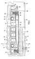
- Fig. 1 shows a drive section of an accumulating conveyor.
- Rollers 10, 12, which are mounted between a side rail, not shown, of the frame of the roller conveyor and a U-profile 14 arranged in the middle, are indicated.
- the roller 10 is mounted on an axis 16 and the roller 12 on an axis 18.
- the U-profile 14 is arranged such that 20 side legs 22 and 24 are directed upwards from the underlying base.
- holes 26 are arranged at a predetermined distance, which are used to fasten rollers.
- An endless chain 28 running over the entire length of the roller conveyor is provided for driving the goods, not shown, which are transported on the rollers 10 and 12.
- the lower run 30 of the chain 28 runs over the base 20.
- chain guide profiles 32 are fastened to the base 20 of the U-profile 14 by means of screws 34.
- the chain guide profiles 32 are not continuous over the entire length of the U-profile 14 but have a suitable length.
- a rib 34 with a rectangular cross section is arranged on the top of each chain guide profile 32, on which 10 the rollers 36 of the chain slide, the chain links 38 being guided laterally on the rib 34.
- the chain guide profiles 32 * and the lower run 30 of the chain 28 are covered by U-profile sections 40, the opening of which is directed towards the base 20 of the U-profile 14.
- the U-profile sections 40 carry hose sections 42, with the aid of which the upper run 44 of the chain 28 can be lifted in sections when compressed air is pressed into the interior of the hose section 42 via a line (not shown) which is connected to a connecting nozzle 46.
- the spout 46 is inserted in a closure piece 48 which closes the front end of the hose.
- a screw 50 is guided through the base of the U-profile 40 and the closure piece 48.
- the screw 50 is screwed into a pin 52 which presses the tube wall against the closure piece 48 and thus closes the tube.
- the rear end 54 of the hose 42 is folded over.
- a through the base of the U-profile 40 screw 56 is screwed into a pin 58, whereby the end 54 is compressed airtight.
- a metal rail 60 is placed on the top of the tube piece 42.
- a support and guide profile 62 stands on this metal rail 60, on the upper side of which the upper run 44 of the chain 28 runs.
- the support and guide profile 62 is designed as a comb profile and has tines 64 on, which are double-walled to save material and weight.
- the distance between two prongs is equal to the distance between two holes 26, so that the support and guide profile 62 can be arranged regardless of the distance between the rollers 10 and 12.
- the axle journals 16 and 18 run for the Rollers 10 and 12 and their corresponding rollers arranged between the opposite spar of the support frame and the U-profile 14 between two prongs 64.
- the base surface 66 between two prongs 64 is preferably rounded, so that the profile fits well on the axle journals 16 and 18 can hang up.
- a chain guide 78 is formed, which consists of a rib which is approximately rectangular in cross section. The rollers 80 of the upper run 44 of the chain 28 slide on this rib 78 and the chain links 82 are guided laterally on the chain guide 78.
- knobs 84 which, after the support and guide profile 62 have been attached to the axes 16 and 18, provide a kind of snap fit, so that the support and guide profile 62 can no longer be released without the use of force. A transport lock is thus achieved.
- a bushing 88 is provided on each axle journal 16 and 18 whose end faces on the inside of the legs 22 and 24. These bushings 88 therefore serve as spacers. 2 shows stub axles 89 and 90 for the roller 10 and a corresponding roller on the other side, which are integrally formed on the journal 16.
- rollers 100, 102 are mounted on the ends 106 and 108 of an axle pin 109 which project beyond the outside of a U-profile 104.
- a chain 110 is guided in the U-profile 104 and the upper run 112 of the chain is raised via hose sections 114, on which are arranged a support and guide profile 118 via a metal rail 116, which, as in the embodiment according to FIGS Tines are formed.
- a support and guide profile 120 is tapered at the end 122, while the support and guide profile 118 is formed at the end 124 with an inner recess, so that the end 122 of the support and guide profile 120 can be inserted into the end 124 of the support and guide profile 118.
- the further structural details shown in FIGS. 3 to 5 correspond to those shown in FIGS. 1 and 2.
- axle journals result in a stroke limitation for the support and guide profile, since the metal rail lies against the underside of the axle journals when the hose section is inflated, and a further lifting of the upper run of the chain is prevented.
Landscapes
- Engineering & Computer Science (AREA)
- Mechanical Engineering (AREA)
- Framework For Endless Conveyors (AREA)
- Rollers For Roller Conveyors For Transfer (AREA)
- Attitude Control For Articles On Conveyors (AREA)
- Chain Conveyers (AREA)
Abstract
@ Bei der Vorrichtung zur akkumulierenden Förderung von Gütern, die in Form einer Rollenbahn mit Rollen (10, 12) ausgebildet ist und bei welcher eine über aufblasbare Schlauchabschnitte (42) eine Kette (28) mit den zu fördernden Gütern in Angriff bringbar ist, ist zwischen der Kette (28) und jedem Schlauchabschnitt (42) ein Trag-und Führungsprofil für die Kette (28) in einem U-Profil (14) angeordnet. Das Trag-und Führungsprofil (62) ist in Form eines Kammes mit Zinken (64) ausgebildet, wobei zwischen jeweils zwei Zinken (64) die die Rollen (10, 12) tragenden Achszapfen (16, 18) aufgenommen werden können. Durch diese Anordnung kann das U-Profil (14) sehr schmal ausgebildet werden.
Description
Die Erfindung betrifft eine Vorrichtung zur akkumulierenden Förderung von Gütern, mit einer Rollenbahn, mit einer über aufblasbare Schlauchabschnitte mit den zu fördernden Gütern in Angriff bringbare Kette, wobei zwischen der Kette und jedem Schlauchabschnitt ein Trag-und Führungsprofil angeordnet ist und die Kette, die Trag-und Führungsprofile und die Schlauchabschnitte in einem nach oben hin offenen U-Profil angeordnet sind.The invention relates to a device for the accumulating conveyance of goods, with a roller conveyor, with a chain which can be attacked with the goods to be conveyed via inflatable tube sections, a carrying and guide profile being arranged between the chain and each tube section and the chain, the carrier and guide profiles and the hose sections are arranged in an upwardly open U-profile.
Derartige Förderer dienen insbesondere dazu, in gleichartigen Kisten oder auf gleichartigen Paletten angeordnete Güter auf einer Rollenbahn zu transportieren, wobei sich die Güter vom Anfang der Rollenbahn her aufstauen und beispielsweise von einem Stapler abgenommen werden können. Sobald die erste Kiste oder die erste Palette von der Rollenbahn entnommen ist, werden die nachfolgenden Güter um einen Abschnitt weiter befördert und neue Güter werden soweit transportiert bis sie den ersten unbesetzten Abschnitt erreicht haben.Such conveyors are used in particular to transport goods arranged in identical boxes or on similar pallets on a roller conveyor, the goods accumulating from the beginning of the roller conveyor and being able to be removed, for example, by a forklift. As soon as the first box or the first pallet has been removed from the roller conveyor, the following goods are transported one section further and new goods are transported until they have reached the first unoccupied section.
Es ist bekannt, die Rollen der Rollenbahn zweizuteilen, d.h. jeweils zwei fluchtende Rollen sind mit einem Ende am Seitenrahmen der Rollenbahn und mit dem inneren Ende über einseitig gelagerte Achsstummel an einem mittig in der Rollenbahn verlaufenden U-Profil befestigt. In diesem U-Profil ist eine Kette angebracht, die während des Betriebs der Rollenbahn ständig angetrieben ist und an den Enden der Rollenbahn umgelenkt wird. Zum Fördern der Güter wird die Kette abschnittsweise über Schlauchabschnitte und zwischen den Schlauchabschnitten und der Kette angeordneten Trag-und Führungsprofilen angehoben, damit die Kette an der Unterseite der zu fördernden Kisten oder Paletten angreifen kann. Bei diesen bekannten Vorrichtungen ist das in der Mitte angeordnete U-Profil sehr breit ausgebildet, um die Achsstummel zur Lagerung der Rollen und die dazwischen angeordneten Trag-und Führungsprofile aufzunehmen.It is known to split the roles of the roller conveyor in two, i.e. two aligned rollers are attached at one end to the side frame of the roller conveyor and with the inner end via stub axles mounted on one side to a U-profile that runs centrally in the roller conveyor. A chain is attached in this U-profile, which is constantly driven during operation of the roller conveyor and is deflected at the ends of the roller conveyor. To convey the goods, the chain is raised in sections over hose sections and support and guide profiles arranged between the hose sections and the chain, so that the chain can engage the underside of the boxes or pallets to be conveyed. In these known devices, the U-profile arranged in the middle is made very wide in order to accommodate the stub axles for mounting the rollers and the support and guide profiles arranged between them.
Der Erfindung liegt die Aufgabe zugrunde, eine gattungsgemäße. Vorrichtung so auszugestalten, daß der aus Kette, lauchabschnitten und Trag-und Führungsprofilen bestehende Antrieb kompakter und sicherer ist und die Lagerung der Rollen verbessert wird.The invention has for its object a generic. To design the device so that the drive consisting of chain, leek sections and support and guide profiles is more compact and safer and the storage of the rollers is improved.
Die Lösung dieser Aufgabe wird erfindungsgemäß dadurch erreicht, daß das Trag-und Führungsprofil als Kammprofil ausgebildet ist und daß die Zinken nach unten zu dem Schlauchabschnitt gerichtet sind. Bei einem derart ausgebildeten Trag-und Führungsprofil ergibt sich erfindungsgemäß der große Vorteil, daß die zur Lagerung der Rollen an dem U-Profil angeordneten Achsstummel als das U-Profil durchsetzende Zapfen ausgebildet werden können, deren Enden zur Lagerung der Rollen seitlich aus dem U-Profil herausstehen. In den Zwischenräumen zwischen jeweils zwei benachbarten Zinken des Trag-und Führungsprofils können die Achszapfen aufgenommen werden, sodaß das U-Profil mit geringerer Breite ausgebildet werden kann, da das Trag-und Führungsprofil nicht zwischen den Enden zweier Achsstummel verlaufen muß.This object is achieved according to the invention in that the supporting and guiding profile is designed as a comb profile and in that the tines are directed downward toward the hose section. With a support and guide profile designed in this way, there is the great advantage according to the invention that the stub axles arranged for mounting the rollers on the U-profile can be designed as pins penetrating the U-profile, the ends of which for mounting the rollers laterally from the U- Stand out profile. The axle journals can be received in the spaces between two adjacent tines of the support and guide profile, so that the U-profile can be made narrower, since the support and guide profile does not have to run between the ends of two axle stubs.
Gemäß einer bevorzugten Ausführungsform sind die Zinken doppelwandig ausgebildet und die Basisfläche zwischen den Zinken ist ausgerundet-Durch diese Ausbildung wird Material und Gewicht bei dem Trag-und Führungsprofil eingespart und durch die Ausrundung kann sich das Trag-und Führungsprofil gut auf die Achszapfen auflegen, wenn durch den Schlauch kein Anheben des Profils erfolgt. Dadurch wird gleichzeitig erreicht, daß bei nicht aufgeblasenem Schlauch das Trag-und Führungsprofil, das auf den Achszapfen aufsitzt, den Schlauch nicht belastet.According to a preferred embodiment, the tines are double-walled and the base surface between the tines is rounded. This configuration saves material and weight in the support and guide profile, and the rounding allows the support and guide profile to rest well on the axle journal if there is no lifting of the profile through the hose. It is thereby achieved at the same time that, when the hose is not inflated, the carrying and guide profile, which is seated on the axle journal, does not load the hose.
In weiterer Ausbildung sind an der den Zinken gegenüberliegenden Oberfläche des Trag-und Führungsprofils Seitenschenkel angeordnet, welche vorzugsweise nach außen einfach oder doppelt umgebogen sein können. Diese Seitenschenkel verbessern die Seitenführung des Trag-und Führungsprofils während des Betriebs, d.h. während des Anhebens und Absenkens der Kette.In a further embodiment, side legs are arranged on the surface of the support and guide profile opposite the tines, which can preferably be bent outwards once or twice. These side legs improve the lateral guidance of the support and guide profile during operation, i.e. while raising and lowering the chain.
Ferner ist vorzugsweise an der den Zinken gegenüberliegenden Oberfläche, also zwischen den Seitenschenkeln, in der Mitte eine Kettenführung an dem Trag-und Führungsprofil angeordnet, die vorzugsweise aus einer im Querschnitt rechteckigen Rippe besteht, sodaß die Rollen der Kette auf dieser Rippe aufliegen und die verbindenden Kettenglieder seitlich vorbeistreichen.Furthermore, on the surface opposite the tines, ie between the side legs, a chain guide is arranged in the middle on the support and guide profile, which preferably consists of a rib with a rectangular cross section, so that the rollers of the chain rest on this rib and the connecting ones Swipe chain links sideways.
Um eine Art Transportsicherung zu erbringen sind in Ausgestaltung der Erfindung an den Enden der Zinken Noppen angeordnet, so daß die Trag- und Führungsprofile mit den Achszapfen eine Art Schnappsitz erbringen. Damit wird verhindert, daß beim Transport oder Einbau der Abschnitte die Trag-und Führungsprofile aus dem U-Profil fallen können.In order to provide a kind of transport lock, in an embodiment of the invention, knobs are arranged at the ends of the tines, so that the support and guide profiles provide a kind of snap fit with the axle journals. This prevents the support and guide profiles from falling out of the U-profile during transport or installation of the sections.
Um die Verbindung zweier benachbarter Trag- und Führungsprofile fließend zu gestalten,ist vorzugsweise jedes Trag-und Führungsprofil zur Ausbildung von Überlappungsstößen an einem Ende verjüngt und am anderen Ende mit einer inneren Ausnehmung ausgebildet, so daß ein Ende des Trag-und Führungsprofils ein Ende eines anderen Trag-und Führungsprofils übergreift, während das andere Ende des ersten Trag-und Führungsprofils seinerseits übergriffen wird.In order to make the connection between two adjacent support and guide profiles fluent, each support and guide profile is preferably tapered at one end to form overlap joints and formed with an inner recess at the other end, so that one end of the Support and guide profile overlaps one end of another support and guide profile, while the other end of the first support and guide profile is in turn overlapped.
Um zu vermeiden, daß bei der Anordnung der Achszapfen beim Anziehen der Befestigungsmuttern eine Verformung des U-Profils eintritt sind vorzugsweise auf den Achszapfen im Inneren des U-Profils Abstandsbuchsen angeordnet, die mit ihren Stirnflächen gegen die Innenflächen des U-Profils anstehen.In order to prevent the U-profile from deforming when the fastening nuts are tightened when the axle pins are arranged, spacer sleeves are preferably arranged on the axle pins in the interior of the U-profile, and their end faces abut against the inner surfaces of the U-profile.
In Weiterbildung der Erfindung ist zwischen jedem Trag-und Führungsprofil und dem zugehörigen Schlauchabschnitt eine Metallschiene angeordnet, so daß die Zinkenenden auf dieser Metallschiene aufstehen und eine Beschädigung des Schlauches vermieden wird. Die Schlauchabschnitte liegen auf U-Profilen auf, die mit ihrer Öffnung nach unten gerichtet auf der Basis des durchgehenden U-Profils angeordnet sind. Innerhalb dieser die Schlauchabschnitte tragenden U-Profile sind auf der Basis des durchgehenden U-Profils Kettenführungsprofile angeordnet, um das Untertrum der umlaufenden Kette zu führen. Diese Kettenführungsprofile weisen vorzugsweise eine im Querschnitt rechteckige Rippe auf, auf welcher die Rollen der Kette gleiten.In a further development of the invention, a metal rail is arranged between each support and guide profile and the associated hose section, so that the tine ends stand on this metal rail and damage to the hose is avoided. The tube sections rest on U-profiles, which are arranged with their opening facing downwards on the basis of the continuous U-profile. Chain guide profiles are arranged on the basis of the continuous U profile within these U profiles, which carry the hose sections, in order to guide the lower run of the circulating chain. These chain guide profiles preferably have a rib which is rectangular in cross section and on which the rollers of the chain slide.
Gemäß einer bevorzugten Ausführungsform sind die Trag-und Führungsprofile und die Kettenführungsprofile aus Kunststoff und insbesondere aus Nylon. Um eine Führung für die auf den umgekehrt angeordneten U-Profilen vorgesehenen Schlauchabschnitte zu erbringen, weisen die Schlauchabschnitte an den Enden nach oben hin abragende Führungszapfen auf, die zwischen Zinken des Trag-und Führungsprofils aufgenommen sind.According to a preferred embodiment, the support and guide profiles and the chain guide profiles are made of plastic and in particular of nylon. In order to provide guidance for the hose sections provided on the inverted U-profiles, the hose sections have guide pins protruding upwards at the ends, which are received between prongs of the support and guide profiles.
Ausführungsbeispiele der Erfindung werden nachstehend anhand der Zeichnung erläutert. Es zeigt:
- Fig. 1 einen Abschnitt des Antriebs eines akkumulierenden Förderers im Schnitt,
- Fig. 2 einen Schnitt gemäß der Linie 11-11 von Fig.1,
- Fig. 3 einen Schnitt durch den Antrieb einer abgewandelten Ausführungsform eines akkumulierenden Förderers,
- Fig. 4 einen Schnitt gemäß der Linie IV-IV von Fig. 3 und
- Fig. 5 einen Schnitt gemäß der Linie V-V von Fig. 3.
- 1 shows a section of the drive of an accumulating conveyor in section,
- 2 shows a section along the line 11-11 of Figure 1,
- 3 shows a section through the drive of a modified embodiment of an accumulating conveyor,
- Fig. 4 is a section along the line IV-IV of Fig. 3 and
- 5 shows a section along the line VV of FIG. 3rd
Fig. 1 zeigt einen Antriebsabschnitt eines akkumulierenden Förderers. Rollen 10, 12, die zwischen einem nicht dargestellten Seitenholm des Rahmens der Rollenbahn und einem in der Mitte angeordneten U-Profil 14 gelagert sind, sind angedeutet. Die Rolle 10 ist auf einer Achse 16 und die Rolle 12 auf einer Achse 18 gelagert. Das U-Profil 14 ist derart angeordnet, daß von der untenliegenden Basis 20 Seitenschenkel 22 und 24 nach oben gerichtet sind. In den SeitenschenkeIn sind in vorgegebenem Abstand Bohrungen 26 angeordnet, welche der Befestigung von Rollen dienen. Zum Antrieb der auf den Rollen 10 und 12 transportierten,nichtdargestellten Gütern ist eine endlose, über die gesamte Länge der Rollenbahn umlaufende Kette 28 vorgesehen. Das Untertrum 30 der Kette 28 verläuft über der Basis 20. Zur Führung des Untertrums 30 sind Kettenführungsprofile 32 über Schrauben 34 auf der Basis 20 des U-Profifs 14 befestigt. Die Kettenführungsprofile 32 sind nicht über die gesamte Länge des U-Profils 14 durchgehend sondern weisen eine geeignete Länge auf. Wie aus Fig. 2 zu ersehen ist, ist an der Oberseite jedes Kettenführungsprofils 32 eine im Querschnitt rechteckige Rippe 34 angeordnet, auf welcher 10 die Rollen 36 der Kette gleiten, wobei die Kettenglieder 38 seitlich an der Rippe 34 geführt werden.Fig. 1 shows a drive section of an accumulating conveyor.
Die Kettenführungsprofile 32* und das Untertrum 30 der Kette 28 werden abgedeckt von U-Profilabschnitten 40, deren Öffnung näch unten zu der Basis 20 des U-Profils 14 gerichtet ist. Die U-Profilabschnitte 40 tragen Schlauchabschnitte 42, mit deren Hilfe das Obertrum 44 der Kette 28 abschnittsweise angehoben werden kann, wenn über eine nicht dargestellte Leitung, die an einer Anschlußtülle 46 angeschlossen ist, Druckluft in das Innere des Schlauchabschnitts 42 gepreßt wird. Die Tülle 46 ist in einem Verschlußstück 48 eingesetzt, das das vordere Ende des Schlauches verschließt. Dazu ist eine Schraube 50 durch die Basis des U-Profils 40 und das Verschlußstück 48 geführt. An der Oberseite des' Schlauchstückes 42 ist die Schraube 50 in einen Zapfen 52 eingeschraubt, der die Schlauchwandung gegen das Verschlußstück 48 preßt und damit den Schlauch verschließt. Das hintere Ende 54 des Schlauches 42 ist umgefaltet. Eine durch die Basis des U-Profils 40 verlaufende Schraube 56 ist in einen Zapfen 58 eingeschraubt, womit das Ende 54 luftdicht zusammengepreßt wird.The
Auf der Oberseite des Schlauchstückes 42 ist eine MetaIIschiene 60 aufgelegt. Auf dieser Metallschiene 60 steht 85 ein Trag-und Führungsprofil 62 auf, auf dessen Oberseite das Obertrum 44 der Kette 28 läuft. Das Trag-und Führungsprofil 62 ist als Kammprofil ausgebildet und weist Zinken 64 auf, die zur Einsparnis von Material und Gewicht doppel wandig ausgebildet sind. Der Abstand zweier Zinken ist gleich dem Abstand zweier Löcher 26, so daß das Trag-und Führungsprofil 62 angeordnet werden kann unabhängig von dem Abstand der Rollen 10 und 12. Bei angeordnetem Trag-und Führungsprofil 62 verlaufen die Achs-zapfen 16 und 18 für die Rollen 10 und 12 und deren zwischen dem gegenüberliegenden Holm des Tragrahmens und dem U-Profil 14 angeordnete entsprechende Rollen zwischen zwei Zinken 64. Dazu ist die Basisfläche 66 zwischen zwei Zinken 64 vorzugsweise ausgerundet, so daß sich das Profil gut auf die Achszapfen 16 und 18 auflegen kann.A
Während sich die Zinken 64 von einer Tragfläche 68 nach unten erstrecken, erstrecken sich von der Oberseite der Tragfläche 68 Seitenschenkel 70 und 72 nach oben. Diese Seitenschenkel, deren Enden 74 bzw. 76 einfach oder doppelt umgebogen sein können, verbessern die Seitenführung des Trag-und Führungsprofils 62 und die Enden können sich bei nicht aufgeblasenem Schlauch auf die Enden der Schenkel 22 und 24 des U-Profils 14 aufsetzen. In der Mitte der Fläche 68 und deren Oberseite zwischen den Seitenschenkeln 70 und 72 ist eine Kettenführung 78 angeformt, die aus einer im Querschnitt etwa rechteckigen Rippe besteht. Die Rollen 80 des Obertrums 44 der Kette 28 gleiten auf dieser Rippe 78 und die Kettenglieder 82 werden seitlich an der Kettenführung 78 geführt.While the
An den Zinken 64 sind Noppen 84 vorgesehen, die nach Aufstecken des Trag-und Führungsprofils 62 auf die Achsen 16 und 18 eine Art Schnappsitz erbringen, so daß das Tragund Führungsprofil 62 ohne Kraftanwendung nicht mehr gelöst werden kann. Damit wird eine Transportsicherung erreicht.On the
Um zu vermeiden, daß bei Anbringen der Achszapfen 16 und 18 in dem U-Profil 14 durch zu starkes Anziehen einer Mutter 86 eine Verformung der Schenkel 22 und 24 des U-Profils 14 eintritt, ist an jedem Achszapfen 16 und 18 eine Buchse 88 vorgesehen, deren Stirnseiten an den Innenseiten der Schenkel 22 und 24 ansteht. Diese Buchsen 88 dienen demnach als Abstandshalter. Aus Fig. 2 sind an dem Achszapfen 16 angeformte Achsstummel 89 bzw. 90 für die Rolle 10 und eine entsprechende Rolle auf der anderen Seite gezeigt.In order to prevent the
Bei der in den Fig. 3 bis 5 gezeigten Ausführungsform sind anstelle von breiten Rollen Röllchen 100, 102 an den über die Außenseite eines U-Profils 104 stehenden Enden 106 und 108 eines Achszapfens 109 gelagert. In dem U-Profil 104 ist eine Kette 110 geführt und das Obertrum 112 der Kette wird über Schlauchabschnitte 114 angehoben, auf welchen über eine Metallschiene 116 Trag-und Führungsprofile 118 angeordnet sind, die wie bei der Ausführungsform nach den Fig. 1 und 2 mit Zinken ausgebildet sind.In the embodiment shown in FIGS. 3 to 5, instead of wide rollers,
Wie insbesondere aus Fig. 4 und Fig. 5 zu ersehen ist, ist ein Trag-und Führungsprofil 120 an dem Ende 122 verjüngt ausgebildet, während das Trag-und Führungsprofil 118 an dem Ende 124 mit einer inneren Ausnehmung ausgebildet ist, so daß das Ende 122 des Trag-und Führungsprofils 120 in das Ende 124 des Trag-und Fuhrungsprofils 118 eingesteckt werden kann. Dadurch ergibt sich eine lückenlose Anordnung hintereinander vorgesehener Trag-und Führungsprofile. Die weiteren in den Fig. 3 bis 5 gezeigten konstruktiven Einzelheiten entsprechen den in den Fig. 1 und 2 gezeigten.As can be seen in particular from FIGS. 4 and 5, a support and guide
Die Achszapfen ergeben eine Hubbegrenzung für das Trag-und Führungsprofil, da sich die Metallschiene beim Aufblasen des Schlauchabschnittes an die Unterseite der Achszapfen anlegt und ein weiteres Anheben des Obertrums der Kette verhindert wird.The axle journals result in a stroke limitation for the support and guide profile, since the metal rail lies against the underside of the axle journals when the hose section is inflated, and a further lifting of the upper run of the chain is prevented.
Claims (10)
Applications Claiming Priority (2)
| Application Number | Priority Date | Filing Date | Title |
|---|---|---|---|
| DE8511014U | 1985-04-15 | ||
| DE8511014U DE8511014U1 (en) | 1985-04-15 | 1985-04-15 | Device for the accumulating conveyance of goods |
Publications (2)
| Publication Number | Publication Date |
|---|---|
| EP0200888A2 true EP0200888A2 (en) | 1986-11-12 |
| EP0200888A3 EP0200888A3 (en) | 1987-06-16 |
Family
ID=6779891
Family Applications (1)
| Application Number | Title | Priority Date | Filing Date |
|---|---|---|---|
| EP86103398A Withdrawn EP0200888A3 (en) | 1985-04-15 | 1986-03-13 | Accumulating conveying device for articles |
Country Status (3)
| Country | Link |
|---|---|
| US (1) | US4732265A (en) |
| EP (1) | EP0200888A3 (en) |
| DE (1) | DE8511014U1 (en) |
Cited By (2)
| Publication number | Priority date | Publication date | Assignee | Title |
|---|---|---|---|---|
| CN101332935B (en) * | 2008-08-04 | 2012-12-19 | 周明月 | Bottom-top throwing multi-point discharging belt conveyor |
| CN110789978A (en) * | 2019-11-06 | 2020-02-14 | 赣州东峰自动化设备有限公司 | Pine leaf automatic leaf separating machine used on simulation Christmas tree |
Families Citing this family (6)
| Publication number | Priority date | Publication date | Assignee | Title |
|---|---|---|---|---|
| GB2182907B (en) * | 1985-11-18 | 1989-10-04 | Hydraroll Ltd | Mechanical handling apparatus |
| US5085311A (en) * | 1990-02-27 | 1992-02-04 | Gene Garro | In-line accumulator with zero backline pressure |
| DE4128890C2 (en) * | 1991-08-30 | 1995-02-23 | Germos Fessmann Gmbh & Co Kg | Plant for treating products |
| US5743375A (en) * | 1995-09-11 | 1998-04-28 | Industrial Technology Research Institute | Conveyer transfer apparatus |
| US5810158A (en) * | 1995-12-21 | 1998-09-22 | Mannesmann Dematic Rapistan Corp. | Belt accumulation conveyor |
| GB0418924D0 (en) * | 2004-08-25 | 2004-09-29 | Cornucopia Uk Ltd | Conveyor system |
Family Cites Families (10)
| Publication number | Priority date | Publication date | Assignee | Title |
|---|---|---|---|---|
| US3545596A (en) * | 1968-05-15 | 1970-12-08 | Alvey Inc | Conveyor |
| US3650376A (en) * | 1970-08-17 | 1972-03-21 | Conveyor Systems | Accumulating conveyor |
| US3838769A (en) * | 1973-09-07 | 1974-10-01 | C Traughber | Lift-and-lay conveyor |
| GB1525975A (en) * | 1975-10-02 | 1978-09-27 | Simon Container Mach Ltd | Accumulating conveying systems |
| US4219113A (en) * | 1978-06-16 | 1980-08-26 | Fieser Arthur H | Conveyor for moving heavy dense objects |
| DE3045563A1 (en) * | 1980-12-03 | 1982-07-01 | R. Schindele Fördertechnik KG, 8939 Bad Wörishofen | Stepwise-operation conveyor for e.g. pallets - uses selectively inflated hose to raise linked conveying rollers into contact with pallet bases |
| AU555408B2 (en) * | 1981-08-27 | 1986-09-25 | Hydraroll Ltd. | Roller conveyor handling apparatus |
| DE3134372A1 (en) * | 1981-08-31 | 1983-06-30 | decormetall Karl Becker GmbH, 4902 Bad Salzuflen | Construction element system for devices for conveying, retaining and storing unit loads with transverse and longitudinal supports as well as longitudinal supports for the construction element system |
| FR2560169B1 (en) * | 1984-02-28 | 1986-07-04 | Soule Sa | CONVEYOR WITH FIXED AND MOBILE APRON, IN PARTICULAR FOR ROOMS OR TUNNELS FOR PASTEURIZATION, STERILIZATION, HEATING OR COOLING OF VARIOUS PRODUCTS |
| FR2573372B1 (en) * | 1984-11-19 | 1987-02-06 | Malemant Bertrand | IMPROVEMENTS IN MOUNTING RETRACTABLE TRAILS IN TRANSPORT VEHICLES |
-
1985
- 1985-04-15 DE DE8511014U patent/DE8511014U1/en not_active Expired
-
1986
- 1986-03-13 EP EP86103398A patent/EP0200888A3/en not_active Withdrawn
- 1986-03-31 US US06/846,267 patent/US4732265A/en not_active Expired - Fee Related
Cited By (3)
| Publication number | Priority date | Publication date | Assignee | Title |
|---|---|---|---|---|
| CN101332935B (en) * | 2008-08-04 | 2012-12-19 | 周明月 | Bottom-top throwing multi-point discharging belt conveyor |
| CN110789978A (en) * | 2019-11-06 | 2020-02-14 | 赣州东峰自动化设备有限公司 | Pine leaf automatic leaf separating machine used on simulation Christmas tree |
| CN110789978B (en) * | 2019-11-06 | 2021-01-29 | 赣州东峰自动化设备有限公司 | Pine leaf automatic leaf separating machine used on simulation Christmas tree |
Also Published As
| Publication number | Publication date |
|---|---|
| US4732265A (en) | 1988-03-22 |
| DE8511014U1 (en) | 1985-09-26 |
| EP0200888A3 (en) | 1987-06-16 |
Similar Documents
| Publication | Publication Date | Title |
|---|---|---|
| CH621310A5 (en) | ||
| EP1495937A2 (en) | Transport trolley | |
| AT16353U1 (en) | Transport bag and method for filling and emptying of such a transport bag | |
| EP0158656A1 (en) | Storage installation. | |
| EP0093409B1 (en) | Device for the stable and synchronous conveying of packages for fluids through treatment stations | |
| DE3214044A1 (en) | Device for conveyor appliances | |
| EP0541850A1 (en) | Curvilinear plate conveyor | |
| EP0200888A2 (en) | Accumulating conveying device for articles | |
| EP3625153A2 (en) | Transport attachment, plate conveyor and method | |
| DE1756380A1 (en) | Method and device for the transfer of goods between conveyors in motion | |
| DE10020909A1 (en) | Device for conveying a supply roll | |
| DE10117665A1 (en) | Vertical conveyor in the form of a circulation C-conveyor for the vertical conveying of general cargo | |
| DE3442306C2 (en) | ||
| DE3541364C2 (en) | Supporting link for conveyor belt conveyors | |
| DE2021914A1 (en) | Movable transport frame for piece goods | |
| EP3837192A1 (en) | Transport device | |
| DE3513535A1 (en) | Apparatus for conveying and storing objects arranged in a hanging manner | |
| DE4300621C2 (en) | Storage or storage arrangement | |
| DD262221A5 (en) | CASSETTE MOTION, INS. FOR MOVING BARRIER SLIDES SUPPORTED IN CASSETTES | |
| DE3638580C2 (en) | ||
| EP0143945A1 (en) | Device for stacking, transporting and filling containers | |
| DE8535683U1 (en) | Conveyor device with driven, reinforced belts for transporting loaded pallets | |
| DE19817437C2 (en) | Carrier for transporting workpieces with ejection on both sides | |
| DE2706986B2 (en) | Loading device for loading and unloading the loading area of a transport device | |
| DE19937143C2 (en) | Device for transferring transport goods from one conveyor to at least one other conveyor |
Legal Events
| Date | Code | Title | Description |
|---|---|---|---|
| PUAI | Public reference made under article 153(3) epc to a published international application that has entered the european phase |
Free format text: ORIGINAL CODE: 0009012 |
|
| AK | Designated contracting states |
Kind code of ref document: A2 Designated state(s): AT BE CH DE FR GB IT LI LU NL SE |
|
| PUAB | Information related to the publication of an a document modified or deleted |
Free format text: ORIGINAL CODE: 0009199EPPU |
|
| RA1 | Application published (corrected) |
Date of ref document: 19861217 Kind code of ref document: A2 |
|
| PUAL | Search report despatched |
Free format text: ORIGINAL CODE: 0009013 |
|
| AK | Designated contracting states |
Kind code of ref document: A3 Designated state(s): AT BE CH DE FR GB IT LI LU NL SE |
|
| STAA | Information on the status of an ep patent application or granted ep patent |
Free format text: STATUS: THE APPLICATION IS DEEMED TO BE WITHDRAWN |
|
| 18D | Application deemed to be withdrawn |
Effective date: 19871217 |
|
| RIN1 | Information on inventor provided before grant (corrected) |
Inventor name: VOM STEIN, HANS |