EP0198551A2 - Infra-red intruder detection system - Google Patents
Infra-red intruder detection system Download PDFInfo
- Publication number
- EP0198551A2 EP0198551A2 EP86200614A EP86200614A EP0198551A2 EP 0198551 A2 EP0198551 A2 EP 0198551A2 EP 86200614 A EP86200614 A EP 86200614A EP 86200614 A EP86200614 A EP 86200614A EP 0198551 A2 EP0198551 A2 EP 0198551A2
- Authority
- EP
- European Patent Office
- Prior art keywords
- output
- followed
- infra
- red
- intruder
- Prior art date
- Legal status (The legal status is an assumption and is not a legal conclusion. Google has not performed a legal analysis and makes no representation as to the accuracy of the status listed.)
- Granted
Links
Images


Classifications
-
- G—PHYSICS
- G08—SIGNALLING
- G08B—SIGNALLING SYSTEMS, e.g. PERSONAL CALLING SYSTEMS; ORDER TELEGRAPHS; ALARM SYSTEMS
- G08B13/00—Burglar, theft or intruder alarms
- G08B13/18—Actuation by interference with heat, light, or radiation of shorter wavelength; Actuation by intruding sources of heat, light, or radiation of shorter wavelength
- G08B13/189—Actuation by interference with heat, light, or radiation of shorter wavelength; Actuation by intruding sources of heat, light, or radiation of shorter wavelength using passive radiation detection systems
- G08B13/19—Actuation by interference with heat, light, or radiation of shorter wavelength; Actuation by intruding sources of heat, light, or radiation of shorter wavelength using passive radiation detection systems using infrared-radiation detection systems
- G08B13/191—Actuation by interference with heat, light, or radiation of shorter wavelength; Actuation by intruding sources of heat, light, or radiation of shorter wavelength using passive radiation detection systems using infrared-radiation detection systems using pyroelectric sensor means
-
- H—ELECTRICITY
- H05—ELECTRIC TECHNIQUES NOT OTHERWISE PROVIDED FOR
- H05B—ELECTRIC HEATING; ELECTRIC LIGHT SOURCES NOT OTHERWISE PROVIDED FOR; CIRCUIT ARRANGEMENTS FOR ELECTRIC LIGHT SOURCES, IN GENERAL
- H05B47/00—Circuit arrangements for operating light sources in general, i.e. where the type of light source is not relevant
- H05B47/10—Controlling the light source
- H05B47/105—Controlling the light source in response to determined parameters
- H05B47/115—Controlling the light source in response to determined parameters by determining the presence or movement of objects or living beings
-
- Y—GENERAL TAGGING OF NEW TECHNOLOGICAL DEVELOPMENTS; GENERAL TAGGING OF CROSS-SECTIONAL TECHNOLOGIES SPANNING OVER SEVERAL SECTIONS OF THE IPC; TECHNICAL SUBJECTS COVERED BY FORMER USPC CROSS-REFERENCE ART COLLECTIONS [XRACs] AND DIGESTS
- Y10—TECHNICAL SUBJECTS COVERED BY FORMER USPC
- Y10S—TECHNICAL SUBJECTS COVERED BY FORMER USPC CROSS-REFERENCE ART COLLECTIONS [XRACs] AND DIGESTS
- Y10S250/00—Radiant energy
- Y10S250/01—Passive intrusion detectors
Definitions
- This invention relates to an infra-red intruder detection system, and, in particular, to an infra-red intruder detection system comprising first and second separate channels A and B each having a pyroelectric detector device responsive to infra-red radiation, the radiation receiving areas of the devices being closely spaced, and level detector means responsive to a predetermined output level of one polarity produced by the respective pyroelectric detector device as a result of an infra-red image intruder-related infra-red image moving thereacross to provide a respective output signal in accordance with the detector device output attaining said predetermined level, and circuit means for monitoring output signals of the level detector means in both channels and providing an output in response to output signals occuring in both channels.
- the output from an intruder detection system of this kind may be used to generate an alarm in response to an intruder being detected thereby, the intruder acting as a moving source of infra-red radiation crossing the field of view of the pyroelectric detector devices thus causing the pyroelectric detector devices to produce respective outputs whose magnitude exceed the predetermined levels of the level detector means.
- the system may be used for other movement sensing purposes, for example in remote switching applications for sensing the presence of a person in a room and responding thereto to switch lights on or off, and the term "intruder” should therefore be construed accordingly.
- Two, separate, channels are provided in this known system in order to reduce the risk of false triggering.
- Factors such as electrical noise within pyroelectric detector circuits or external, non-intruder related, infra-red radiation sources may result in the pyroelectric detector circuits producing spurious outputs which could give rise to a misleading output being generated.
- the risk of false triggering is considerably reduced since the likelihood of spurious, intruder simulating, noise signals occuring in both channels in such a manner to produce system response is remote.
- the two channel system allows an alarm to be generated, or a switching function to be performed, on the basis of signal information in both channels.
- Noise interference in one channel only generally will not induce a reaction from the system and a situation where, say, noise spikes occur in both channels simultaneously or almost simultaneously would be very unlikely in view of the random nature of such noise spikes.
- an intruder detection system be able to repond reliably to the presence of an intruder.
- an infra-red intruder detection system comprising first and second separate channels A and B each having a pyroelectric detector device responsive to infra-red radiation, the radiation receiving areas of the devices being closely spaced, and level detector means responsive to a predetermined output level of one polarity produced by the respective pyroelectric detector device as a result of an intruder-related infra-red image moving thereacross to provide a respective output signal in accordance with the detector device output attaining said predetermined level, and circuit means for monitoring output signals of the level detector means in both channels and providing an output in response to output signals occuring in both channels characterised in that in the level detector means of each channel is responsive in addition to a predetermined output level of opposite polarity produced by the respective pyroelectric detector device as a result of an intruder-related infra-red image moving thereacross so that the level detector means of both channels provide output signals, herein referred to a +A, -A, +B, -
- the infra-red image of the intruder presented to the devices moves across the devices correspondingly.
- the two devices are separate, there is typically a small delay between the point in time the image first falls on the radiation receiving sensitive area of the one device and the point in time the image falls on the radiation receiving sensitive area of the other device.
- the detector device of channel A will respond to produce an intruder-indicative output shortly before the detector device of channel B.
- the system according to the invention uses to advantage the fact that a pattern, or sequence, of the output signals of, for example, the positive excursion parts of the level detector means in channels A and B in response to an intruder moving across the detector devices' field of view is +A, as the image falls upon the sensitive area of the detector device of channel A, followed by +A together with +B as the image moves also onto the sensitive area of the detector device of channel B, (bearing in mind that the sensitive areas of the devices are spaced close together and that the size of the focussed image presented is sufficient to cover at least parts of the sensitive areas both detector devices simultaneously), followed by +B as the image moves from the detector device of channel A solely onto the sensitive area of the device of channel B.
- the system in having level detector means associated with each channel which respond to predetermined output levels of both polarity from the detector device concerned, is able to respond more reliably to the presence of a moving intruder.
- An infra-red radiation image passing onto the temperature-change responsive pyroelectric material of the detector device will cause a voltage to be developed across electrodes on the pyroelectric material, this voltage being fed via an associated impedance matching circuit, typically comprising a low-noise FET, to provide an output.
- an associated impedance matching circuit typically comprising a low-noise FET
- each crossing of the detector device by an infra-red image produces dual polarity output voltages.
- the detector device's output voltages are passed to the associated level detector means, comprising for example positive and negative threshold level detector, which responds to predetermined levels of positive and negative output voltages to generate digital pulse signals in accordance therewith for analysis by the circuit means.
- the associated level detector means comprising for example positive and negative threshold level detector, which responds to predetermined levels of positive and negative output voltages to generate digital pulse signals in accordance therewith for analysis by the circuit means.
- the circuit means is preferably further arranged to provide an output in response to predetermined patterns of output signals from the level detector means of both channels comprising either +B, followed by +B together with +A, followed by +A, or -B, followed by -B together with -A, followed by -A.
- the system advantageously is able to detect and respond to an intruder moving also in the opposite direction, wherein the intruder's image passes correspondingly over the detector devices in the opposite direction.
- the circuit means for monitoring output signals of the level detector means is preferably further arranged so as to provide an output also in response to any one of the following additional patterns of output signals from the level detector means of both channels:
- the circuit means further is arranged to provide an output also in response to any one of the following patterns of output signals from the level detector means of both channels:
- the circuit means may further be arranged to inhibit generation of an output if a combination of output signals -A together with +B, or +A together with -B occurs. In this way, the risk of false triggering of the system as a result of mechanical shock to the detector devices is reduced.
- pyroelectric material by virtue of the fact that it also has piezoelectric properties, is sensitive to mechanical shock, whereby the detector devices, when subjected to mechanical shock, produce outputs similar to those associated with intruder images. With the known system, there exists a real risk of false triggering through mechanical shock.
- the aforementioned combinations of output signals have been identified as the kinds of signals typically generated through mechanical shock.
- the system is able to discriminate to some extent the effects of mechanical shocks and thus offers a higher degree of immunity from false triggering as a result of mechanical shocks.
- the circuit means preferably also includes a timing arrangement which, in response to an output signal from either level detector means (+A, -A, +B, -B) defines a timing period window for generation of said output such that only if said predetermined patterns of output signals occur within said timing period, an output is generated.
- the timing period window being of a duration sufficient to allow an intruder's image to pass over both detector devices but not significantly longer, helps prevent false triggering of the system by necessitating that the required, intruder-related, pattern of signals be detected within a predefined time interval and thus reducing the likelihood of spurious signals, for example resulting from noise, causing triggering.
- the radiation receiving areas of the detector devices may be interdigitated so as to occupy a substantially common area. This ensures that the detector devices respond very nearly simultaneously to an incoming infra-red radiation image and enables the timing period window to be kept to a minimum.
- Each of the pyroelectric detector devices may comprise a so-called “dual" detector device having two pyroelectric elements differentially connected.
- a differential detector device having two pyroelectric elements differentially connected.
- uniform changes in input radiation in the fields of view of both elements for example resulting from changes in ambient temperature, background radiation or acoustic noise, will produce voltages across the pair of elements which, since they are connected differentially, cancel out one another whereas a change in input radiation in the field of view of just one element produces a differential output voltage.
- imminity is provided from common mode signals produced by effects such as those mentioned, thereby increasing the overall immunity of the system from false triggering.
- the four elements of the two dual detector devices may be arranged in a linear array with one element of one detector device being positioned closely adjacent to, or interdigitated with, one element of the other detector device.
- the system has two channels, designated respectively A and B, each of which includes a so-called “dual" pyroelectric detector device, 10A and 10B.
- the detector devices each comprise a pair of pyroelectric elements, lla, Ilb, 12a and 12b formed from separate bodies of pyroelectric materials, such as lanthanum and manganese doped lead zirconate titanate, sandwiched between two nichrome electrodes disposed on opposing major surfaces thereof.
- the uppermost electrodes are substantially transmissive to infra-red radiation in a wavelength range to be detected. Unwanted radiation wavelengths may be filtered out.
- the fabrication of the detector devices is well known and as such is not described herein in detail.
- Figure 2 shows the circuit of the detector devices 10A and 10B and as is conventional, the pyroelectric elements are represented in Figure 2 as capacitors and their poling directions indicated by the usual signs.
- the two pyroelectric elements lla, 12a and llb, 12b, of each detector device are electrically connected in parallel opposition between lines 14a, 15a and 14b, 15b, lines 15a and 15b being connected together to ground, such that a differential output from each associated pair of elements is obtained along lines 14a and 14b respectively.
- the lines 14a and 14b are connected respectively to the gates of a Field Effect Transistor Ta and Tb, and two low leakage diodes Dla, D2a and Dlb, D2b, in parallel-opposition connected respectively between the gates of transistors Ta and Tb and lines 15a and 15b.
- a Field Effect Transistor Ta and Tb and two low leakage diodes Dla, D2a and Dlb, D2b, in parallel-opposition connected respectively between the gates of transistors Ta and Tb and lines 15a and 15b.
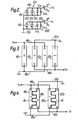
- the pyroelectric elements of the two detector devices 10A and 10B may be arranged parallely as shown in Figure 3 in a linear array with one element of one device disposed between the two, spaced, elements of the other device.
- the elements have generally rectangular radiation receiving sensitive areas of substantially equal size, around 2mm x 0.6mm. Adjacent elements are closely spaced, around 0.2mm apart, (this spacing shown exaggerated in Figure 3) so that, as an infra-red image traverses the elements, transversely of the linear array, the delay between the response of one element to that image and the response from the adjacent element is minimised.
- the elements of the two devices may be shaped with fingers and arranged as shown in Figure 4 parallely with the fingers of respective ones of the elements of each device, which project generally parallel to the direction of travel of the intruder image, being interdigitated.
- the elements again have substantially equal radiation receiving sensitive areas, being around 2.5mm long by lmm wide overall.
- the interdigitated elements are separated by a small meandering gap of around 0.05 to 0.125mm, referenced at 16.
- the two elements of each dual device are spaced apart by around lmm. In this way, each pair of interdigitated elements, for example lla and llb, occupy a substantially common area so that they are able to respond to a moving infra-red image directed thereon very nearly at the same point in time.
- the construction of such interdigitated dual detector devices is described in greater detail in U.K. Patent Application No. 8503240.
- each level detection circuit 21A and 21B comprises two comparators employed as positive and negative threshold level detectors, 22A, 23A and 22B, 23B, the pairs of comparators 22A and 23A, and 22B and 23B respectively making up a window comparator.
- the level detection circuits 21A and 21B are responsive to voltage excursions of predetermined magnitude and of either polarity from the amplifier stages 20A and 20B to produce a specific digital output, namely a logic "one" output pulse in accordance therewith at the appropriate comparator output, the normal quiescent logic of the comparators being a logic "zero" voltage signal.
- the operation of the level detection circuits 21A and 21B is as follows.
- a sufficiently large change in temperature of that element will result in an amplified voltage signal exceeding the predetermined voltage level of, say, the positive voltage excursion comparator 22A so that the comparator 22A is triggered and a logic "one" output is produced thereby whose duration corresponds with the period for which the voltage output from the detector device exceeds the preset level of the comparator.
- the comparator 23A As the infra-red image moves off that element, a similar voltage of opposite polarity will be developed which this time exceeds the predetermined voltage of the other, negative voltage excursion, comparator 23A which responds by producing a logic "one" at its output.
- comparator 22B As the infra-red image moves onto the adjacent pyroelectric element of detector device 10B, a logic "one" is produced by comparator 22B, assuming again the image causes sufficient temperature change in that element, and as the image moves off that element of detector device 10B, comparator 23B produces a logic "one" output.
- the level detection circuits 21A and 21B serve as discriminators to distinguish intruder-indicative outputs from the detector devices 10A and 10B from unwanted, comparatively low-level voltage excursions resulting from, for example, internal or extraneous noise.
- the image moves further across the detector deviceslOA and 10B, it will encounter the adjacent, second, pyroelectric elements of the devices to produce an inverse, second series of outputs from the comparators, since the pyroelectric material of those elements is poled in the opposite direction.
- the logic "one" outputs of the comparators 22A, 23A, 22B, 23B are hereinafter designated +A, -A, +B, -B respectively for simplicity.
- the outputs from the comparators 22A, 23A, 22B, 23B as the intruder's image passes onto an element of device 10A and then onto an element of device 10B to produce a voltage output from each device of certain duration would for example be +A followed directly by +A together with +B (bearing in mind that the adjacent pyroelectric elements of devices 10A and 10B are spaced closely together so that the intruder's image will reach an element of device 10B very soon after the adjacent element of device 10A and within the duration of the output signal from comparator 22A whereby the output signals from 22A and 22B partly overlap) followed directly by +B.
- the four outputs of the level detection circuits 21A and 21B are connected to a pattern recognition signal processing circuit arrangement 25, comprising electronic logic circuits which is arranged to identify patterns, that is, sequences of output signals from the level detection circuits 21A and 21B indicative of an intruder crossing the detector devices field of view and respond thereto to produce an output.
- This output is, in turn, supplied along line 26 to an alarm and/or switching relay circuit 27 which generates an alarm and/or operates switches, for example lighting switches, accordingly.
- the circuit arrangement 25 is designed to identify and respond to the aforementioned pattern of comparator output signals, that is, +A, followed by +A together with +B (resulting from partly overlapping output signals), followed by +B, and also, for increased security, the inverse thereof, namely -A, followed by -A together with -B, followed by -B, these output signals being provided in response to the opposite polarity outputs from the detector devices as the image moves off their respective elements.
- the circuit arrangement 25 is also arranged to respond to the reverse of the aforementioned patterns, that is, either +B, followed by +B together with +A, followed by +A, or -B followed by -B together with -A, followed by -A.
- the circuit arrangement 25 is further arranged to recognise, and respond to, additional patterns of output signals from the level detectioncircuits 21A and 21B. More precisely, the circuit arrangement 25 is designed to respond to additional output signal patterns comprising either the sequence +A, followed directly by +A together with +B, followed by +A again, or the sequence -A, followed directly by -A together with -B, followed directly by -A again. It has been found that by arranging the circuit arrangement 25 to identify and respond to these additional patterns the system is able to detect intruders even more reliably.
- the circuit arrangement 25 is further arranged to identify and respond to the reverse of the additional patterns of output signals from the level detection circuits 21A and 21B mentioned above, that is, either the sequence +B, followed by +B together with +A, followed by +B again, or -B, followed by -B together with -A, followed by -B again.
- the circuit arrangement 25 includes a timer circuit which defines a timing period window following the first of a sequence of output signals from the level detection circuits 21A and 21B. If during the duration of this timing period one of the intruder-indicative patterns of output signals is detected, an output from the circuit arrangement 25 is supplied to the alarm and/or relay switching circuit 27. If, on the other hand, the timing period expires before detection of an intruder-indicative pattern is completed, the output from the circuit arrangement is inhibited.
- the duration of the timing period is pre-selected in dependence upon such parameters as the expected time taken normally for an intruder's image to pass over the detector devices 10A and 10B, itself dependent on, for example, the anticipated distance and speed of the intruder, the size of the image presented to the devices, and the mutual spacing of the pyroelectric elements in the devices. In one embodiment of the invention, using interdigitated elements as described above, a timing duration of around 2.5 seconds has been found to be satisfactory.
- Figure 5 shows the circuit arrangement 25, connected to comparators 22A, 23A, 22B and 23B in greater detail.
- the individual logic gates of this circuit form parts of integrated circuit, there being eight in all, which are designated IC1 through IC8, with individual gates thereof being suffixed with a lower case letter.
- the output of comparator 22A is fed, via a resistor, to one input of AND gate IC7a whose other input is connected to the output of comparator 22B.
- the outputs of both these comparators are connected also to respective inputs of EXCLUSIVE OR gate IC6a.
- the output of gate IC6a is supplied to an input of a flip flop comprising NAND gates ICla and IClb whose output, together with the output of gate IC7a form respective inputs of NAND gate IC5a.
- the output of gate IC5a is connected to an input of a flip flop comprising NAND gates ICld and IClc whose output is supplied to NAND gate IC4d.
- comparators 23A and 23B are likewise connected, via respective resistors, through a similar logic circuit comprising gates IC7b, IC6b, IC2a, IC2b, IC5b, IC2d, IC2c, IC4c and IC6c, the latter gate being shared.
- Gate IC6c being supplied through gates IC6a and IC6b serves to detect any individual comparator transition from its quiescent state. Its output serves on the one hand to reset the flip flops constituted by ICla and IClb, ICld and IClc, IC2a and IC2b, and IC2d and IC2c respectively and, on the other, to initiate operation of a conventional timing circuit comprising a 555 type timer IC10.
- the output of the timing circuit is supplied through an inverting gate IC8a to one input of NAND IC8d.
- the output of gate IC8d in turn is connected to an input of a flip flop constituted by NAND gates IC8a, IC8b whose output is connected, via a resistor, to line 26.
- NAND gates IC4d and IC4c are connected to the inputs of EXCLUSIVE OR gate IC6d.
- the output of this gate is fed to an input of a flip flop comprising NAND gates IC3c and IC3d, the reset input and output respectively of this flip flop being connected with the output of the timing circuit and to the input of AND gate IC7d whose output is fed via a resistor/capacitor holding circuit to the other input of gate IC8d.
- comparators 22B and 23A and 22A and 23B respectively are supplied to NAND gates IC4a and IC4b.
- the outputs of these two gates are supplied to a further AND gate IC7c whose output is connected to the input of a flip flop constituted by IC3a and IC3b, the reset input of this flip flop being connected to the output of the timing circuit. Its output is connected through inverting gate IC5c to the other input of IC7d.
- the components IC1, IC4d, IC6a, IC7a and IC5a of the logic circuit-serve to detect output signal patterns from the comparators comprising either +A, followed by +A together with +B, followed by +B, or +B,. followed by +B together with +A, followed by +A, or +A, followed by +A together with +B, followed by +A, or +B, followed by +A together with +B, followed by +B. If any of these patterns are detected, an output is provided by IC4d accordingly.
- the components IC2, IC4c, IC6b, IC7b and IC5b of the logic circuit operate in a similar fashion to detect the following patterns of output signals from the comparators:-
- the components IC3c, IC3d and IC6d look for outputs from either IC4d and IC4c indicative of any of the above mentioned sequences having been detected and provides an input to IC7d in accordance therewith.
- the components IC4a, IC4b, IC7c, IC3a, IC3b and IC5c serve to detect the particular combinations of output signals from the comparators indicative of mechanical shock, namely either -A together with +B, or +A together with -B. If such a combination is detected, the output of IC5c prohibits gate IC7d from providing an output indicative of one of the predetermined patterns having been detected.
- the output of gate IC7d operates through NAND gates IC8d and IC8a to provide an output along line 26 to the alarm and/or switching relay circuit 27 so as to cause an alarm to be generated or switches to be actuated.
- IC6c detects any individual comparator transition and acts to trigger the timer IC10 of the timing circuit which thereupon supplies a timing signal, inverted by gate IC8c, to gate IC8d for a predetermined duration of around 2.5 seconds.
- the gates IC7d and IC8a to d enable an output to be provided along line 26 if within 2.5 seconds after the first comparator transition has been detected one complete intruder-indicative patterns of output signals is detected and providing that no mechanical shock indicative combinations of output signals is observed.
- the flip flop constituted by IC8a and IC8b may be reset by manual actuation of switch40.
- the system provides greater immunity from false triggering whilst also offering improved intruder detection capability.
- the use of detector devices having interdigitated pyroelectric elements is particularly attractive since it enables the selected timing period, and thus the risk of false triggering caused by random noise, to be reduced to a minimum as a result of the adjacent, interdigitated elements occupying more or less the same sensing area and therefore being able to respond almost simultaneously to an incoming radiation image.
- a multi-segment mirror may be used to collect incoming infra-red radiation and focus the radiation on the detector devices, each segment of the mirror having its own, discrete field of view. In this way, as an intruder moves through the field of view of each mirror segment, a separate image is focussed onto the elements of the devices so that a series of output signal sequences are produced by the comparators for multiple triggering.
- multi-faceted lenses may be used instead. The use of mirrors or lenses ensurethat a well-focussed image and acceptable operating range.
- the system may have detector devices comprising single pyroelectric elements, the elements of the two devices being either arranged closely adjacent one another or interdigitated in a similar manner to that described above.
Landscapes
- Physics & Mathematics (AREA)
- General Physics & Mathematics (AREA)
- Burglar Alarm Systems (AREA)
- Photometry And Measurement Of Optical Pulse Characteristics (AREA)
- Geophysics And Detection Of Objects (AREA)
Abstract
Description
- This invention relates to an infra-red intruder detection system, and, in particular, to an infra-red intruder detection system comprising first and second separate channels A and B each having a pyroelectric detector device responsive to infra-red radiation, the radiation receiving areas of the devices being closely spaced, and level detector means responsive to a predetermined output level of one polarity produced by the respective pyroelectric detector device as a result of an infra-red image intruder-related infra-red image moving thereacross to provide a respective output signal in accordance with the detector device output attaining said predetermined level, and circuit means for monitoring output signals of the level detector means in both channels and providing an output in response to output signals occuring in both channels.
- The output from an intruder detection system of this kind may be used to generate an alarm in response to an intruder being detected thereby, the intruder acting as a moving source of infra-red radiation crossing the field of view of the pyroelectric detector devices thus causing the pyroelectric detector devices to produce respective outputs whose magnitude exceed the predetermined levels of the level detector means.
- The system may be used for other movement sensing purposes, for example in remote switching applications for sensing the presence of a person in a room and responding thereto to switch lights on or off, and the term "intruder" should therefore be construed accordingly.
- Two, separate, channels are provided in this known system in order to reduce the risk of false triggering. Factors such as electrical noise within pyroelectric detector circuits or external, non-intruder related, infra-red radiation sources may result in the pyroelectric detector circuits producing spurious outputs which could give rise to a misleading output being generated. By employing two channels, each having its own pyroelectric detector device, and by requiring that intruder indicative outputs from both detector devices are needed in order for this system to respond, the risk of false triggering is considerably reduced since the likelihood of spurious, intruder simulating, noise signals occuring in both channels in such a manner to produce system response is remote. Thus, the two channel system allows an alarm to be generated, or a switching function to be performed, on the basis of signal information in both channels. Noise interference in one channel only generally will not induce a reaction from the system and a situation where, say, noise spikes occur in both channels simultaneously or almost simultaneously would be very unlikely in view of the random nature of such noise spikes.
- Besides having some immunity from false triggering, it is desirable of course that an intruder detection system be able to repond reliably to the presence of an intruder.
- Whilst the known system has improved false triggering immunity compared with earlier known single channel systems, it has been found that, in use, it can still sometimes prove unreliable in successfully detecting intruders.
- It is an object of the present invention to provide an infra-red intruder detection system which can respond even more reliably to intruders and in which the likelihood of false triggering is reduced still further.
- According to the present invention there is provided an infra-red intruder detection system, comprising first and second separate channels A and B each having a pyroelectric detector device responsive to infra-red radiation, the radiation receiving areas of the devices being closely spaced, and level detector means responsive to a predetermined output level of one polarity produced by the respective pyroelectric detector device as a result of an intruder-related infra-red image moving thereacross to provide a respective output signal in accordance with the detector device output attaining said predetermined level, and circuit means for monitoring output signals of the level detector means in both channels and providing an output in response to output signals occuring in both channels characterised in that in the level detector means of each channel is responsive in addition to a predetermined output level of opposite polarity produced by the respective pyroelectric detector device as a result of an intruder-related infra-red image moving thereacross so that the level detector means of both channels provide output signals, herein referred to a +A, -A, +B, -B, in accordance with said detector device outputs attaining predetermined positive and negative levels in channels A and B respectively, and in that the circuit means for monitoring the level detector means output signals is arranged to provide an output in response to predetermined patterns of output signals indicative of an intruder-related infra-red image moving across the pyroelectric detector devices of both channels comprising either output signals +A, followed by +A together with +B, followed by +B, or -A, followed by -A together with -B, followed by -B.
- Such a system, by looking for both polarity outputs from the detector devices and responding to particular patterns of output signals from the level detector means when those outputs exceed a certain level rather than by looking simply at one polarity outputs from the detector devices and responding merely to the existence of output signals in both channels as with the aforementioned known system, has been found to offer greater reliability in intruder detection and immunity from false triggering. This system according to the invention is therefore a significant improvement over the earlier known system.
- As an intruder moves across the field of view of the two pyroelectric detector devices of the system, the infra-red image of the intruder presented to the devices, which may be collected and focussed by means of, for example, a mirror or lens arrangement, moves across the devices correspondingly. Because the two devices are separate, there is typically a small delay between the point in time the image first falls on the radiation receiving sensitive area of the one device and the point in time the image falls on the radiation receiving sensitive area of the other device. Thus, for example, the detector device of channel A will respond to produce an intruder-indicative output shortly before the detector device of channel B. By making the physical separation of the two detector devices as small as possible, the time delay is minimised and may in certain cases be almost negligible. The system according to the invention uses to advantage the fact that a pattern, or sequence, of the output signals of, for example, the positive excursion parts of the level detector means in channels A and B in response to an intruder moving across the detector devices' field of view is +A, as the image falls upon the sensitive area of the detector device of channel A, followed by +A together with +B as the image moves also onto the sensitive area of the detector device of channel B, (bearing in mind that the sensitive areas of the devices are spaced close together and that the size of the focussed image presented is sufficient to cover at least parts of the sensitive areas both detector devices simultaneously), followed by +B as the image moves from the detector device of channel A solely onto the sensitive area of the device of channel B.
- The system, in having level detector means associated with each channel which respond to predetermined output levels of both polarity from the detector device concerned, is able to respond more reliably to the presence of a moving intruder. An infra-red radiation image passing onto the temperature-change responsive pyroelectric material of the detector device will cause a voltage to be developed across electrodes on the pyroelectric material, this voltage being fed via an associated impedance matching circuit, typically comprising a low-noise FET, to provide an output. As the infra-red image moves off the pyroelectric material a voltage of opposite polarity is developed, which voltage is again fed via the impedance matching circuit to provide a further output. Hence each crossing of the detector device by an infra-red image produces dual polarity output voltages. Following amplification, the detector device's output voltages are passed to the associated level detector means, comprising for example positive and negative threshold level detector, which responds to predetermined levels of positive and negative output voltages to generate digital pulse signals in accordance therewith for analysis by the circuit means. By looking at both the positive and negative detector device output voltages produced in response to a single infra-red image, the system is able to detect intruders with a higher degree of reliability than, for example, a system employing either a positive or a negative level threshold detector alone. If the system fails for some reason to respond to an intruders's image passing on to the detector devices, it can still respond to the opposite polarity output voltages produced as the image passes off the detector devices.
- The circuit means is preferably further arranged to provide an output in response to predetermined patterns of output signals from the level detector means of both channels comprising either +B, followed by +B together with +A, followed by +A, or -B, followed by -B together with -A, followed by -A. In this way, the system advantageously is able to detect and respond to an intruder moving also in the opposite direction, wherein the intruder's image passes correspondingly over the detector devices in the opposite direction.
- The circuit means for monitoring output signals of the level detector means is preferably further arranged so as to provide an output also in response to any one of the following additional patterns of output signals from the level detector means of both channels:
- a) +A, followed by +A together with +B, followed by +A
- and b) -A, followed by -A together with -B, followed by -A.
- Surprisingly, it has been found that by looking for these additional, unexpected patterns the system in use has proved to be even more reliable in detecting intruders. Whereas it may be thought that looking for the first-mentioned patterns of level detector means output signals should be sufficient to readily identify an intruder, tests have revealed that as a result of arranging the circuit means so as to look for and respond to these additional patterns of output signals from the level detector means in both channels, the system is actually more effective and more reliable in detecting and responding to intruders to provide an output in accordance therewith.
- Preferably, the circuit means further is arranged to provide an output also in response to any one of the following patterns of output signals from the level detector means of both channels:
- a) +B, followed by +A together with +B, followed by +B,
- and b) -B, followed by -A together with -B, followed by -B. This has the advantage of enabling the system to detect movement of an intruder in the opposite direction as well, that is, with the intruder's image passing firstly onto the detector device of channel B and then onto the detector device of channel A.
- The circuit means may further be arranged to inhibit generation of an output if a combination of output signals -A together with +B, or +A together with -B occurs. In this way, the risk of false triggering of the system as a result of mechanical shock to the detector devices is reduced. As is well known, pyroelectric material, by virtue of the fact that it also has piezoelectric properties, is sensitive to mechanical shock, whereby the detector devices, when subjected to mechanical shock, produce outputs similar to those associated with intruder images. With the known system, there exists a real risk of false triggering through mechanical shock. However, the aforementioned combinations of output signals have been identified as the kinds of signals typically generated through mechanical shock. By looking for these particular combinations and operating in response to detection of such combinations in effect to ignore the sequence of signals in which they are contained, the system is able to discriminate to some extent the effects of mechanical shocks and thus offers a higher degree of immunity from false triggering as a result of mechanical shocks.
- The circuit means preferably also includes a timing arrangement which, in response to an output signal from either level detector means (+A, -A, +B, -B) defines a timing period window for generation of said output such that only if said predetermined patterns of output signals occur within said timing period, an output is generated. The timing period window, being of a duration sufficient to allow an intruder's image to pass over both detector devices but not significantly longer, helps prevent false triggering of the system by necessitating that the required, intruder-related, pattern of signals be detected within a predefined time interval and thus reducing the likelihood of spurious signals, for example resulting from noise, causing triggering.
- The radiation receiving areas of the detector devices, defined by respective pyroelectric elements may be interdigitated so as to occupy a substantially common area. This ensures that the detector devices respond very nearly simultaneously to an incoming infra-red radiation image and enables the timing period window to be kept to a minimum.
- Each of the pyroelectric detector devices may comprise a so-called "dual" detector device having two pyroelectric elements differentially connected. In this way, uniform changes in input radiation in the fields of view of both elements, for example resulting from changes in ambient temperature, background radiation or acoustic noise, will produce voltages across the pair of elements which, since they are connected differentially, cancel out one another whereas a change in input radiation in the field of view of just one element produces a differential output voltage. Hence imminity is provided from common mode signals produced by effects such as those mentioned, thereby increasing the overall immunity of the system from false triggering.
- In this embodiment the four elements of the two dual detector devices may be arranged in a linear array with one element of one detector device being positioned closely adjacent to, or interdigitated with, one element of the other detector device.
- An infra-red intruder detection system in accordance with the invention will now be described, by way of example, with reference to the accompanying drawings in which:-
- Figure 1 is a block schematic diagram of the system,
- Figure 2 is a circuit diagram of two, interconnected pyroelectric detector devices of the system shown in Figure 1,
- Figure 3 and 4 show schematically in plan view respective alternative arrangements of the pyroelectric elements of the detector devices of Figure 2, and
- Figure 5 is a schematic diagram of a circuit forming part of the system.
- Referring to Figure 1, the system has two channels, designated respectively A and B, each of which includes a so-called "dual" pyroelectric detector device, 10A and 10B. As can be seen from Figure 2, the detector devices each comprise a pair of pyroelectric elements, lla, Ilb, 12a and 12b formed from separate bodies of pyroelectric materials, such as lanthanum and manganese doped lead zirconate titanate, sandwiched between two nichrome electrodes disposed on opposing major surfaces thereof. The uppermost electrodes are substantially transmissive to infra-red radiation in a wavelength range to be detected. Unwanted radiation wavelengths may be filtered out. The fabrication of the detector devices is well known and as such is not described herein in detail. Figure 2 shows the circuit of the
detector devices lines lines 15a and 15b being connected together to ground, such that a differential output from each associated pair of elements is obtained alonglines 14a and 14b respectively. - The
lines 14a and 14b are connected respectively to the gates of a Field Effect Transistor Ta and Tb, and two low leakage diodes Dla, D2a and Dlb, D2b, in parallel-opposition connected respectively between the gates of transistors Ta and Tb andlines 15a and 15b. For more detailed information about the circuit of each detector device, reference is invited to U.K. Patent Specification Nos. 1580403 and 2046431B. Briefly, it can be said that the diode arrangement of each device protects the gate of its associated Field Effect transistor (which forms part of an impedance matching circuit) from excessive voltages and limits progressively the pyroelectric voltage resulting from large changes in ambient temperature. - In operation, voltages produced across the two elements of each device, for example lla and 12a, as a result of the same temperature change to both elements due to the same radiation change in the fields of view of both elements will cancel one another out because they are connected differentially. On the other hand, when the change in temperature of one element as determined by the change in radiation in the field of view of that one element is not accompanied by a corresponding change in temperature of the other element as determined by the change in radiation in the field of view of the other element, a differential output voltage is created at the gate of the associated transistor T. The use of such dual detector devices in intruder detection systems is highly beneficial as, for example, fluctuations in the thermal state of the background scene and acoustic noise produce no effective output from the device, thus eliminating "environmental noise" and providing some protection against false triggering in the system.
- The pyroelectric elements of the two
detector devices - Alternatively, the elements of the two devices may be shaped with fingers and arranged as shown in Figure 4 parallely with the fingers of respective ones of the elements of each device, which project generally parallel to the direction of travel of the intruder image, being interdigitated. The elements again have substantially equal radiation receiving sensitive areas, being around 2.5mm long by lmm wide overall. The interdigitated elements are separated by a small meandering gap of around 0.05 to 0.125mm, referenced at 16. The two elements of each dual device are spaced apart by around lmm. In this way, each pair of interdigitated elements, for example lla and llb, occupy a substantially common area so that they are able to respond to a moving infra-red image directed thereon very nearly at the same point in time. The construction of such interdigitated dual detector devices is described in greater detail in U.K. Patent Application No. 8503240.
- Referring again to Figure 1, the source terminals of the transistors Ta and Tb, constituting the outputs of the
detector devices symbols level detection circuits 21A and 21B respectively. Eachlevel detection circuit 21A and 21B comprises two comparators employed as positive and negative threshold level detectors, 22A, 23A and 22B, 23B, the pairs ofcomparators - The
level detection circuits 21A and 21B are responsive to voltage excursions of predetermined magnitude and of either polarity from the amplifier stages 20A and 20B to produce a specific digital output, namely a logic "one" output pulse in accordance therewith at the appropriate comparator output, the normal quiescent logic of the comparators being a logic "zero" voltage signal. The operation of thelevel detection circuits 21A and 21B is as follows. Considering the case where an intruder is moving across the field of view of thedetector devices detector device 10A, a voltage of a first polarity is developed across that element which is amplified by the amplifier stages 20A and fed to the inputs of both comparators of the level detection circuit 21A. A sufficiently large change in temperature of that element, as would be expected in the case of an intruder's infra-red image, will result in an amplified voltage signal exceeding the predetermined voltage level of, say, the positivevoltage excursion comparator 22A so that thecomparator 22A is triggered and a logic "one" output is produced thereby whose duration corresponds with the period for which the voltage output from the detector device exceeds the preset level of the comparator. As the infra-red image moves off that element, a similar voltage of opposite polarity will be developed which this time exceeds the predetermined voltage of the other, negative voltage excursion,comparator 23A which responds by producing a logic "one" at its output. - Similarly, as the infra-red image moves onto the adjacent pyroelectric element of
detector device 10B, a logic "one" is produced bycomparator 22B, assuming again the image causes sufficient temperature change in that element, and as the image moves off that element ofdetector device 10B,comparator 23B produces a logic "one" output. - Thus the
level detection circuits 21A and 21B serve as discriminators to distinguish intruder-indicative outputs from thedetector devices - The logic "one" outputs of the
comparators - In response to an intruder moving in one direction across the field of view of
detector devices comparators device 10A and then onto an element ofdevice 10B to produce a voltage output from each device of certain duration, would for example be +A followed directly by +A together with +B (bearing in mind that the adjacent pyroelectric elements ofdevices device 10B very soon after the adjacent element ofdevice 10A and within the duration of the output signal fromcomparator 22A whereby the output signals from 22A and 22B partly overlap) followed directly by +B. - The four outputs of the
level detection circuits 21A and 21B are connected to a pattern recognition signalprocessing circuit arrangement 25, comprising electronic logic circuits which is arranged to identify patterns, that is, sequences of output signals from thelevel detection circuits 21A and 21B indicative of an intruder crossing the detector devices field of view and respond thereto to produce an output. This output is, in turn, supplied alongline 26 to an alarm and/or switchingrelay circuit 27 which generates an alarm and/or operates switches, for example lighting switches, accordingly. - The
circuit arrangement 25 is designed to identify and respond to the aforementioned pattern of comparator output signals, that is, +A, followed by +A together with +B (resulting from partly overlapping output signals), followed by +B, and also, for increased security, the inverse thereof, namely -A, followed by -A together with -B, followed by -B, these output signals being provided in response to the opposite polarity outputs from the detector devices as the image moves off their respective elements. - To allow for the fact that an intruder may move in the opposite direction, the
circuit arrangement 25 is also arranged to respond to the reverse of the aforementioned patterns, that is, either +B, followed by +B together with +A, followed by +A, or -B followed by -B together with -A, followed by -A. - The
circuit arrangement 25 is further arranged to recognise, and respond to, additional patterns of output signals from thelevel detectioncircuits 21A and 21B. More precisely, thecircuit arrangement 25 is designed to respond to additional output signal patterns comprising either the sequence +A, followed directly by +A together with +B, followed by +A again, or the sequence -A, followed directly by -A together with -B, followed directly by -A again. It has been found that by arranging thecircuit arrangement 25 to identify and respond to these additional patterns the system is able to detect intruders even more reliably. In comparative tests between a system arranged to respond to the first-mentioned signal patterns alone and a system arranged to respond to these additional patterns as well, the former system, whilst having improved detection capability over the earlier known system, could on certain remote occasions fail to successfully identify intruder-like inputs whereas the latter system had an even higher success rate. Both systems had a generally similar performance as regards false triggering events in response to non-intruder like inputs. This suggests that the additional patterns of signals looked for in the latter system, may be considered as associated uniquely with intruder-like inputs and, when used in conjunction with the first-mentioned patterns, are advantageous in identifying intruders, although the precise reason for this is not entirely clear. - So as to allow for detection of intruders moving in the opposite direction, the
circuit arrangement 25 is further arranged to identify and respond to the reverse of the additional patterns of output signals from thelevel detection circuits 21A and 21B mentioned above, that is, either the sequence +B, followed by +B together with +A, followed by +B again, or -B, followed by -B together with -A, followed by -B again. - Tests carried out using the above described system with the view to attempting to identify uniquely shock-induced output signal patterns indicative of the
detector devices level detection circuits 21A and 21B comprising either -A together with +B, or +A together with -B can prove suitable for such identification purposes. Using this finding, thecircuit arrangement 25 is further arranged to lookfor these shock-related induced combinations of output signals and, upon their detection, to inhibit the generation of an output therefrom. - The
circuit arrangement 25 includes a timer circuit which defines a timing period window following the first of a sequence of output signals from thelevel detection circuits 21A and 21B. If during the duration of this timing period one of the intruder-indicative patterns of output signals is detected, an output from thecircuit arrangement 25 is supplied to the alarm and/or relay switchingcircuit 27. If, on the other hand, the timing period expires before detection of an intruder-indicative pattern is completed, the output from the circuit arrangement is inhibited. The duration of the timing period is pre-selected in dependence upon such parameters as the expected time taken normally for an intruder's image to pass over thedetector devices - Figure 5 shows the
circuit arrangement 25, connected tocomparators - The output of
comparator 22A is fed, via a resistor, to one input of AND gate IC7a whose other input is connected to the output ofcomparator 22B. The outputs of both these comparators are connected also to respective inputs of EXCLUSIVE OR gate IC6a. The output of gate IC6a is supplied to an input of a flip flop comprising NAND gates ICla and IClb whose output, together with the output of gate IC7a form respective inputs of NAND gate IC5a. The output of gate IC5a is connected to an input of a flip flop comprising NAND gates ICld and IClc whose output is supplied to NAND gate IC4d. The other input of this gate is connected to the output of gate IC6a. Respective inputs of ICIc and ICIa are both connected to the output of EXCLUSIVE OR gate IC6c, one input of which is connected to the output of gate IC6a. - The outputs of
comparators - Gate IC6c, being supplied through gates IC6a and IC6b serves to detect any individual comparator transition from its quiescent state. Its output serves on the one hand to reset the flip flops constituted by ICla and IClb, ICld and IClc, IC2a and IC2b, and IC2d and IC2c respectively and, on the other, to initiate operation of a conventional timing circuit comprising a 555 type timer IC10. The output of the timing circuit is supplied through an inverting gate IC8a to one input of NAND IC8d. The output of gate IC8d in turn is connected to an input of a flip flop constituted by NAND gates IC8a, IC8b whose output is connected, via a resistor, to
line 26. - The outputs of NAND gates IC4d and IC4c are connected to the inputs of EXCLUSIVE OR gate IC6d. The output of this gate is fed to an input of a flip flop comprising NAND gates IC3c and IC3d, the reset input and output respectively of this flip flop being connected with the output of the timing circuit and to the input of AND gate IC7d whose output is fed via a resistor/capacitor holding circuit to the other input of gate IC8d.
- The outputs of
comparators - In use, the components IC1, IC4d, IC6a, IC7a and IC5a of the logic circuit-serve to detect output signal patterns from the comparators comprising either +A, followed by +A together with +B, followed by +B, or +B,. followed by +B together with +A, followed by +A, or +A, followed by +A together with +B, followed by +A, or +B, followed by +A together with +B, followed by +B. If any of these patterns are detected, an output is provided by IC4d accordingly.
- The components IC2, IC4c, IC6b, IC7b and IC5b of the logic circuit operate in a similar fashion to detect the following patterns of output signals from the comparators:-
- -A, followed by -A together with -B, followed by -B, or -B, followed by -A together with -B, followed by -A, or -A, followed by -A together with -B, followed by -A, or -B, followed by -A together with -B, followed by -B. If any of these patterns are detected, an output is provided by IC4c accordingly.
- The components IC3c, IC3d and IC6d look for outputs from either IC4d and IC4c indicative of any of the above mentioned sequences having been detected and provides an input to IC7d in accordance therewith.
- The components IC4a, IC4b, IC7c, IC3a, IC3b and IC5c serve to detect the particular combinations of output signals from the comparators indicative of mechanical shock, namely either -A together with +B, or +A together with -B. If such a combination is detected, the output of IC5c prohibits gate IC7d from providing an output indicative of one of the predetermined patterns having been detected. If the gate IC7d is not so prohibited and one of the aforementioned intruder-related patterns is detected, and in dependence on the output of the timing circuit as will be described, the output of gate IC7d operates through NAND gates IC8d and IC8a to provide an output along
line 26 to the alarm and/or switchingrelay circuit 27 so as to cause an alarm to be generated or switches to be actuated. - As previously mentioned, IC6c detects any individual comparator transition and acts to trigger the timer IC10 of the timing circuit which thereupon supplies a timing signal, inverted by gate IC8c, to gate IC8d for a predetermined duration of around 2.5 seconds. The gates IC7d and IC8a to d enable an output to be provided along
line 26 if within 2.5 seconds after the first comparator transition has been detected one complete intruder-indicative patterns of output signals is detected and providing that no mechanical shock indicative combinations of output signals is observed. - Following an alarm output being generated, the flip flop constituted by IC8a and IC8b may be reset by manual actuation of switch40.
- It is envisaged that the various gates and timing circuit may be implemented in a semi-custom integrated circuit.
- By utilising pattern recognition signal processing in the manner described, the system provides greater immunity from false triggering whilst also offering improved intruder detection capability. The use of detector devices having interdigitated pyroelectric elements is particularly attractive since it enables the selected timing period, and thus the risk of false triggering caused by random noise, to be reduced to a minimum as a result of the adjacent, interdigitated elements occupying more or less the same sensing area and therefore being able to respond almost simultaneously to an incoming radiation image.
- A multi-segment mirror, not shown in the drawings, may be used to collect incoming infra-red radiation and focus the radiation on the detector devices, each segment of the mirror having its own, discrete field of view. In this way, as an intruder moves through the field of view of each mirror segment, a separate image is focussed onto the elements of the devices so that a series of output signal sequences are produced by the comparators for multiple triggering. In an alternative arrangement, multi-faceted lenses may be used instead. The use of mirrors or lenses ensurethat a well-focussed image and acceptable operating range.
- Whilst in the described embodiment dual detector devices each having two differentially connected pyroelectric elements are used in order to provide immunity from common mode signal producing effects such as those generated by variations in ambient temperature, background radiation and noise, in another embodiment of the invention the system may have detector devices comprising single pyroelectric elements, the elements of the two devices being either arranged closely adjacent one another or interdigitated in a similar manner to that described above.
Claims (10)
Applications Claiming Priority (2)
| Application Number | Priority Date | Filing Date | Title |
|---|---|---|---|
| GB8509627 | 1985-04-15 | ||
| GB08509627A GB2174224B (en) | 1985-04-15 | 1985-04-15 | Infra-red intruder detection system |
Publications (3)
| Publication Number | Publication Date |
|---|---|
| EP0198551A2 true EP0198551A2 (en) | 1986-10-22 |
| EP0198551A3 EP0198551A3 (en) | 1988-03-23 |
| EP0198551B1 EP0198551B1 (en) | 1991-08-21 |
Family
ID=10577673
Family Applications (1)
| Application Number | Title | Priority Date | Filing Date |
|---|---|---|---|
| EP19860200614 Expired - Lifetime EP0198551B1 (en) | 1985-04-15 | 1986-04-11 | Infra-red intruder detection system |
Country Status (7)
| Country | Link |
|---|---|
| US (1) | US4704533A (en) |
| EP (1) | EP0198551B1 (en) |
| JP (1) | JPH0831192B2 (en) |
| AU (1) | AU5606186A (en) |
| DE (1) | DE3680936D1 (en) |
| ES (1) | ES8707361A1 (en) |
| GB (1) | GB2174224B (en) |
Cited By (6)
| Publication number | Priority date | Publication date | Assignee | Title |
|---|---|---|---|---|
| EP0296766A3 (en) * | 1987-06-19 | 1989-12-13 | Sanyo Electric Co., Ltd. | Intrusion detection system |
| EP0333376A3 (en) * | 1988-03-18 | 1991-04-17 | Aritech B.V. | Improved infrared detector |
| GB2317486B (en) * | 1995-06-22 | 2000-01-12 | David John Dando | Intrusion sensing systems |
| GB2352106A (en) * | 1999-07-14 | 2001-01-17 | David John Matthews | Direction-sensitive warning panel |
| EP1900260A4 (en) * | 2005-06-02 | 2014-06-25 | Hyo-Goo Kim | Sensing system for recognition of direction of moving body |
| EP3067870A1 (en) * | 2015-03-11 | 2016-09-14 | Philips Lighting Holding B.V. | Suppression of popcorn noise in passive infrared detector |
Families Citing this family (34)
| Publication number | Priority date | Publication date | Assignee | Title |
|---|---|---|---|---|
| GB8605394D0 (en) * | 1986-03-05 | 1986-05-08 | Nat Radiological Protection Bo | Radiation detector |
| JPS63242241A (en) * | 1987-03-31 | 1988-10-07 | 株式会社東芝 | Trouble detector of moving quantity detection means |
| DE8705296U1 (en) * | 1987-04-09 | 1988-08-04 | Heimann Gmbh, 6200 Wiesbaden | Infrared detector |
| JPH0786537B2 (en) * | 1987-09-26 | 1995-09-20 | 松下電工株式会社 | Human body detection device |
| US4894601A (en) * | 1988-06-16 | 1990-01-16 | Watkins Harley Jim E | Testing and battery exercising method and control for an emergency lighting unit |
| FR2641871B1 (en) * | 1989-01-18 | 1991-07-26 | Telecommunications Sa | SYSTEM FOR DETERMINING THE POSITION OF AT LEAST ONE TARGET BY TRIANGULATION |
| US5134292A (en) * | 1989-02-07 | 1992-07-28 | Nippon Mining Co., Ltd. | Moving object detector and moving object detecting system |
| US4963749A (en) * | 1989-02-28 | 1990-10-16 | Detection Systems, Inc. | Quad element intrusion detection |
| JP2552728B2 (en) * | 1989-05-31 | 1996-11-13 | 富士通株式会社 | Infrared surveillance system |
| CA1302541C (en) * | 1989-08-07 | 1992-06-02 | Shmuel Hershkovitz | Integrating passive infrared intrusion detector and method |
| US5291020A (en) * | 1992-01-07 | 1994-03-01 | Intelectron Products Company | Method and apparatus for detecting direction and speed using PIR sensor |
| GB2286042B (en) * | 1994-01-27 | 1998-07-29 | Security Enclosures Ltd | Wide-angle infra-red detection apparatus |
| US5524129A (en) * | 1994-06-23 | 1996-06-04 | Ronald K. Pettigrew | Portable counter and data storage system |
| WO1997029453A1 (en) | 1996-02-09 | 1997-08-14 | Tetra Laval Holdings & Finance S.A. | Device and method for checking patterns disposed on a material strip and the material strip |
| US6166625A (en) | 1996-09-26 | 2000-12-26 | Donnelly Corporation | Pyroelectric intrusion detection in motor vehicles |
| PL181650B1 (en) | 1996-12-30 | 2001-08-31 | Jan Kuklinski | Optical system for converting ultraviolet radiation |
| WO1999053278A1 (en) * | 1998-04-15 | 1999-10-21 | Steinel Gmbh & Co. Kg | Sensor device and method for operating a sensor device |
| GB9809152D0 (en) * | 1998-04-30 | 1998-07-01 | Guardall Ltd | Electromagnetic radiation sensing device |
| US6390529B1 (en) | 1999-03-24 | 2002-05-21 | Donnelly Corporation | Safety release for a trunk of a vehicle |
| US6783167B2 (en) | 1999-03-24 | 2004-08-31 | Donnelly Corporation | Safety system for a closed compartment of a vehicle |
| US6086131A (en) | 1999-03-24 | 2000-07-11 | Donnelly Corporation | Safety handle for trunk of vehicle |
| US6485081B1 (en) | 1999-03-24 | 2002-11-26 | Donnelly Corporation | Safety system for a closed compartment of a vehicle |
| US6774791B2 (en) * | 1999-06-09 | 2004-08-10 | Electronics Line (E.L) Ltd. | Method and apparatus for detecting moving objects, particularly intrusions |
| JP4092438B2 (en) | 1999-08-19 | 2008-05-28 | オプテックス株式会社 | Intrusion detection method and apparatus |
| US6768420B2 (en) | 2000-11-16 | 2004-07-27 | Donnelly Corporation | Vehicle compartment occupancy detection system |
| US8258932B2 (en) | 2004-11-22 | 2012-09-04 | Donnelly Corporation | Occupant detection system for vehicle |
| WO2006100672A2 (en) * | 2005-03-21 | 2006-09-28 | Visonic Ltd. | Passive infra-red detectors |
| GB2453484B (en) * | 2006-07-27 | 2009-12-02 | Visonic Ltd | Passive infrared detectors |
| GB2509884B (en) | 2011-11-16 | 2018-10-17 | Tyco Fire & Security Gmbh | Motion detection systems and methodologies |
| CN104627030A (en) | 2013-11-13 | 2015-05-20 | 光宝科技股份有限公司 | Carrier safety system and safety detection and processing method applied to same |
| CN105793679B (en) * | 2013-12-09 | 2019-01-18 | 格立威系统有限公司 | motion detection |
| US9405120B2 (en) | 2014-11-19 | 2016-08-02 | Magna Electronics Solutions Gmbh | Head-up display and vehicle using the same |
| WO2017136485A1 (en) | 2016-02-03 | 2017-08-10 | Greenwave Systems PTE Ltd. | Motion sensor using linear array of irdetectors |
| WO2017147462A1 (en) | 2016-02-24 | 2017-08-31 | Greenwave Systems PTE Ltd. | Motion sensor for occupancy detection and intrusion detection |
Family Cites Families (14)
| Publication number | Priority date | Publication date | Assignee | Title |
|---|---|---|---|---|
| GB1116877A (en) * | 1965-07-30 | 1968-06-12 | Graviner Colnbrook Ltd | Improvements relating to radiation detectors |
| US3524180A (en) * | 1967-01-27 | 1970-08-11 | Santa Barbara Res Center | Passive intrusion detecting system |
| BE790286A (en) * | 1971-10-25 | 1973-02-15 | Licentia Gmbh | INDICATOR DEVICE FOR DETECTION OF TEMPERATURE DIFFERENCES |
| US3928843A (en) * | 1974-06-24 | 1975-12-23 | Optical Coating Laboratory Inc | Dual channel infrared intrusion alarm system |
| GB1580403A (en) * | 1977-04-19 | 1980-12-03 | Philips Electronic Associated | Pyroelectric detector circuits and devices |
| GB2046431B (en) * | 1979-04-12 | 1983-06-15 | Philips Electronic Associated | Pyroelectric detector protection circuit |
| US4342987A (en) * | 1979-09-10 | 1982-08-03 | Rossin Corporation | Intruder detection system |
| US4364030A (en) * | 1979-09-10 | 1982-12-14 | Rossin John A | Intruder detection system |
| DE3128256A1 (en) * | 1981-07-17 | 1983-02-03 | Richard Hirschmann Radiotechnisches Werk, 7300 Esslingen | MOTION DETECTORS FOR SPACE MONITORING |
| JPS58182522A (en) * | 1982-04-20 | 1983-10-25 | Sanyo Electric Co Ltd | Pyroelectric type infrared detector |
| JPS58213396A (en) * | 1982-06-05 | 1983-12-12 | 竹中エンジニアリング工業株式会社 | Ommateal type burglarproof sensor system |
| EP0107042B1 (en) * | 1982-10-01 | 1987-01-07 | Cerberus Ag | Infrared detector for spotting an intruder in an area |
| JPS59195179A (en) * | 1983-04-20 | 1984-11-06 | Uro Denshi Kogyo Kk | Alarming device for intruder |
| US4614938A (en) * | 1984-05-21 | 1986-09-30 | Pittway Corporation | Dual channel pyroelectric intrusion detector |
-
1985
- 1985-04-15 GB GB08509627A patent/GB2174224B/en not_active Expired
-
1986
- 1986-04-08 US US06/849,603 patent/US4704533A/en not_active Expired - Fee Related
- 1986-04-11 DE DE8686200614T patent/DE3680936D1/en not_active Expired - Lifetime
- 1986-04-11 EP EP19860200614 patent/EP0198551B1/en not_active Expired - Lifetime
- 1986-04-11 ES ES553893A patent/ES8707361A1/en not_active Expired
- 1986-04-14 AU AU56061/86A patent/AU5606186A/en not_active Abandoned
- 1986-04-14 JP JP61084418A patent/JPH0831192B2/en not_active Expired - Lifetime
Cited By (8)
| Publication number | Priority date | Publication date | Assignee | Title |
|---|---|---|---|---|
| EP0296766A3 (en) * | 1987-06-19 | 1989-12-13 | Sanyo Electric Co., Ltd. | Intrusion detection system |
| US4943800A (en) * | 1987-06-19 | 1990-07-24 | Sanyo Electric Co., Ltd. | Intrusion detection system using three pyroelectric sensors |
| EP0333376A3 (en) * | 1988-03-18 | 1991-04-17 | Aritech B.V. | Improved infrared detector |
| GB2317486B (en) * | 1995-06-22 | 2000-01-12 | David John Dando | Intrusion sensing systems |
| GB2352106A (en) * | 1999-07-14 | 2001-01-17 | David John Matthews | Direction-sensitive warning panel |
| EP1900260A4 (en) * | 2005-06-02 | 2014-06-25 | Hyo-Goo Kim | Sensing system for recognition of direction of moving body |
| EP3067870A1 (en) * | 2015-03-11 | 2016-09-14 | Philips Lighting Holding B.V. | Suppression of popcorn noise in passive infrared detector |
| WO2016142184A1 (en) * | 2015-03-11 | 2016-09-15 | Philips Lighting Holding B.V. | Sensor noise suppression |
Also Published As
| Publication number | Publication date |
|---|---|
| AU5606186A (en) | 1986-10-23 |
| EP0198551A3 (en) | 1988-03-23 |
| GB2174224B (en) | 1988-07-13 |
| JPH0831192B2 (en) | 1996-03-27 |
| ES553893A0 (en) | 1987-07-16 |
| ES8707361A1 (en) | 1987-07-16 |
| US4704533A (en) | 1987-11-03 |
| DE3680936D1 (en) | 1991-09-26 |
| JPS61281398A (en) | 1986-12-11 |
| GB2174224A (en) | 1986-10-29 |
| EP0198551B1 (en) | 1991-08-21 |
Similar Documents
| Publication | Publication Date | Title |
|---|---|---|
| EP0198551B1 (en) | Infra-red intruder detection system | |
| US4864136A (en) | Passive infrared detection system with three-element, single-channel, pyroelectric detector | |
| US4697081A (en) | Infra-red radiation detector devices | |
| US4441023A (en) | High output differential pyroelectric sensor | |
| US5045702A (en) | Infrared intrustion detector | |
| US4225786A (en) | Infrared detection system | |
| US4529874A (en) | Motion detector for space surveillance | |
| US5126718A (en) | Intrusion detection system | |
| US4742337A (en) | Light-curtain area security system | |
| US4364030A (en) | Intruder detection system | |
| US3631434A (en) | Passive intrusion detector | |
| US3760399A (en) | Intrusion detector | |
| US7183912B2 (en) | PIR motion sensor utilizing sum and difference sensor signals | |
| US4418335A (en) | Infrared intrusion detector with pyroelectric sensor and charge amplifier | |
| US20040140430A1 (en) | PIR motion sensor | |
| US4963749A (en) | Quad element intrusion detection | |
| US7399970B2 (en) | PIR motion sensor | |
| US5309147A (en) | Motion detector with improved signal discrimination | |
| USRE29082E (en) | Intrusion detector | |
| US3634844A (en) | Tamperproof alarm construction | |
| JP3317117B2 (en) | Pyroelectric infrared sensor | |
| JPH05325053A (en) | Burglar sensor | |
| JPH0145119B2 (en) | ||
| JP2983424B2 (en) | Pyroelectric infrared detector | |
| WO2001073713A1 (en) | Improved detector |
Legal Events
| Date | Code | Title | Description |
|---|---|---|---|
| PUAI | Public reference made under article 153(3) epc to a published international application that has entered the european phase |
Free format text: ORIGINAL CODE: 0009012 |
|
| AK | Designated contracting states |
Kind code of ref document: A2 Designated state(s): CH DE FR GB IT LI |
|
| PUAL | Search report despatched |
Free format text: ORIGINAL CODE: 0009013 |
|
| AK | Designated contracting states |
Kind code of ref document: A3 Designated state(s): CH DE FR GB IT LI |
|
| RAP3 | Party data changed (applicant data changed or rights of an application transferred) |
Owner name: N.V. PHILIPS' GLOEILAMPENFABRIEKEN Owner name: PHILIPS ELECTRONIC AND ASSOCIATED INDUSTRIES LIMIT |
|
| 17P | Request for examination filed |
Effective date: 19880902 |
|
| 17Q | First examination report despatched |
Effective date: 19901207 |
|
| GRAA | (expected) grant |
Free format text: ORIGINAL CODE: 0009210 |
|
| AK | Designated contracting states |
Kind code of ref document: B1 Designated state(s): CH DE FR GB IT LI |
|
| REF | Corresponds to: |
Ref document number: 3680936 Country of ref document: DE Date of ref document: 19910926 |
|
| ITF | It: translation for a ep patent filed | ||
| ET | Fr: translation filed | ||
| RAP4 | Party data changed (patent owner data changed or rights of a patent transferred) |
Owner name: N.V. PHILIPS' GLOEILAMPENFABRIEKEN Owner name: PHILIPS ELECTRONICS UK LIMITED |
|
| PLBE | No opposition filed within time limit |
Free format text: ORIGINAL CODE: 0009261 |
|
| STAA | Information on the status of an ep patent application or granted ep patent |
Free format text: STATUS: NO OPPOSITION FILED WITHIN TIME LIMIT |
|
| 26N | No opposition filed | ||
| ITPR | It: changes in ownership of a european patent |
Owner name: CAMBIO RAGIONE SOCIALE;PHILIPS ELECTRONICS N.V. |
|
| REG | Reference to a national code |
Ref country code: CH Ref legal event code: PFA Free format text: PHILIPS ELECTRONICS N.V. |
|
| REG | Reference to a national code |
Ref country code: FR Ref legal event code: CD |
|
| PGFP | Annual fee paid to national office [announced via postgrant information from national office to epo] |
Ref country code: GB Payment date: 19970401 Year of fee payment: 12 |
|
| PGFP | Annual fee paid to national office [announced via postgrant information from national office to epo] |
Ref country code: FR Payment date: 19970422 Year of fee payment: 12 |
|
| PGFP | Annual fee paid to national office [announced via postgrant information from national office to epo] |
Ref country code: DE Payment date: 19970624 Year of fee payment: 12 |
|
| PGFP | Annual fee paid to national office [announced via postgrant information from national office to epo] |
Ref country code: CH Payment date: 19970717 Year of fee payment: 12 |
|
| PG25 | Lapsed in a contracting state [announced via postgrant information from national office to epo] |
Ref country code: GB Free format text: LAPSE BECAUSE OF NON-PAYMENT OF DUE FEES Effective date: 19980411 |
|
| PG25 | Lapsed in a contracting state [announced via postgrant information from national office to epo] |
Ref country code: LI Free format text: LAPSE BECAUSE OF THE APPLICANT RENOUNCES Effective date: 19980430 Ref country code: FR Free format text: THE PATENT HAS BEEN ANNULLED BY A DECISION OF A NATIONAL AUTHORITY Effective date: 19980430 Ref country code: CH Free format text: LAPSE BECAUSE OF THE APPLICANT RENOUNCES Effective date: 19980430 |
|
| REG | Reference to a national code |
Ref country code: CH Ref legal event code: PL |
|
| GBPC | Gb: european patent ceased through non-payment of renewal fee |
Effective date: 19980411 |
|
| PG25 | Lapsed in a contracting state [announced via postgrant information from national office to epo] |
Ref country code: DE Free format text: LAPSE BECAUSE OF NON-PAYMENT OF DUE FEES Effective date: 19990202 |
|
| REG | Reference to a national code |
Ref country code: FR Ref legal event code: ST |
|
| PG25 | Lapsed in a contracting state [announced via postgrant information from national office to epo] |
Ref country code: IT Free format text: LAPSE BECAUSE OF NON-PAYMENT OF DUE FEES;WARNING: LAPSES OF ITALIAN PATENTS WITH EFFECTIVE DATE BEFORE 2007 MAY HAVE OCCURRED AT ANY TIME BEFORE 2007. THE CORRECT EFFECTIVE DATE MAY BE DIFFERENT FROM THE ONE RECORDED. Effective date: 20050411 |