EP0127849A2 - Relay - Google Patents
Relay Download PDFInfo
- Publication number
- EP0127849A2 EP0127849A2 EP84105922A EP84105922A EP0127849A2 EP 0127849 A2 EP0127849 A2 EP 0127849A2 EP 84105922 A EP84105922 A EP 84105922A EP 84105922 A EP84105922 A EP 84105922A EP 0127849 A2 EP0127849 A2 EP 0127849A2
- Authority
- EP
- European Patent Office
- Prior art keywords
- adapter plate
- relay
- tabs
- spring
- contact
- Prior art date
- Legal status (The legal status is an assumption and is not a legal conclusion. Google has not performed a legal analysis and makes no representation as to the accuracy of the status listed.)
- Granted
Links
Images


Classifications
-
- H—ELECTRICITY
- H01—ELECTRIC ELEMENTS
- H01H—ELECTRIC SWITCHES; RELAYS; SELECTORS; EMERGENCY PROTECTIVE DEVICES
- H01H50/00—Details of electromagnetic relays
- H01H50/02—Bases; Casings; Covers
- H01H50/04—Mounting complete relay or separate parts of relay on a base or inside a case
- H01H50/041—Details concerning assembly of relays
- H01H50/042—Different parts are assembled by insertion without extra mounting facilities like screws, in an isolated mounting part, e.g. stack mounting on a coil-support
Definitions
- the present invention relates to a relay, in particular a small relay, with a spring bracket which serves to hold the magnetic coil and the contact spring set.
- relays are often provided with flat plug connections, on the basis of which measure it is possible to use such relays in a very simple manner in existing electrical circuits, or to be able to replace them in the event of a fault.
- the individual flat plugs are connected to the connections of the contact spring set with the aid of conductors arranged inside the relay, which have to be fastened to the connections of the flat plug and the contact spring set, for example by soldering.
- a relay in particular a small relay, which has a greatly simplified structure in view of the existing, separate spatial conditions - in the connecting conductor to be routed separately within the relay can be dispensed with.
- this is achieved in that the individual contact springs of the contact spring set 5 are provided at the bottom 5 with integrally molded tabs, which are guided through slots arranged in the bottom wall of the spring bracket and are fixed in position in this area both positively and positively.
- the present invention is based on the knowledge that the intended contact spring set of the relay in question can be modified such that the line connections of the contact spring set provided in the interior of the respective relay normally come to lie on the outside of the relay, in which case the relevant line connections directly in Form of flat plug connections can be formed, so that the provision of arranged within the relay, separately to be laid connecting conductors can be dispensed with.
- the position of the contact spring set with the one-piece molded flat plugs is expediently carried out within an adapter plate, which can be fastened to the bottom wall of the spring bracket of the relay in question using ribs and grooves.
- the adapter plate provided must be designed in such a way that both the tabs to be located on the outside of the relay and the contact springs arranged on the inside of the relay are fixed in position with the aid of the same.
- the positional fixation of these elements can take place either by extrusion coating, gluing or laterally pushing on the contact spring set provided with the flat plugs into slots provided within the adapter plate.
- the slots or guide grooves provided within the adapter plate are expediently designed in a Z-shape, which on the one hand ensures a good position Locking of the individual contact springs with their tabs comes about, while on the other hand the mutual distance between the individual tabs is increased while maintaining a relatively small mutual distance between the individual tabs, which often appears desirable or necessary in view of the required insulation properties.
- additional ribs or grooves are provided on the outside of the adapter plate, which run between the individual flat plugs.
- the provided adapter plate is finally designed such that the relay can be attached within an electrical circuit using the provided adapter plate.
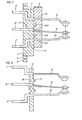
- the small relay 1 shown in FIGS. 1-3 contains a drive system, the coil of which can be controlled via coil connections 29, 30.
- the armature acts on a contact spring set, which consists of three contact springs 14 to 16.
- These contact springs 14 to 16 are integrally formed with tabs 2, 22 protruding from the bottom surface of the relay.
- the contact springs 14 to 16 thereby lead through slots 23 of a spring bracket 21 therethrough, and are straight or Z-shaped slots 7, 27 a p Ada terplatte 3 is fixed in position.
- the adapter plate 3 serves to ensure that the plug-in forces acting on the flat connectors 2, 22 cannot be transmitted to the spring bracket 3 and thus to the contact springs 14 to 16.
- a protruding tab 4 is provided on the central tab 22, which engages in a corresponding latching opening 5 in the region of the guide groove 27.
- the adapter plate 3 can be pushed onto the spring bracket 21 of the small relay 1 in the plane perpendicular to the drawing plane of FIG.
- the adapter plate 3 For the positive connection of the adapter plate 3 with the bottom surface of the spring bracket 21, it is provided that on the bottom surface facing side of the adapter plate 3 projecting ribs are present, which engage in corresponding grooves 3 on the bottom surface of the spring bracket 21.
- projections 10 are provided with holes 6 provided in addition, by means of which not shown Fixed To g ungs- passage means with which the adapter plate can be mounted on any mounting face.
- FIGS 4 to 6 show further details of the adapter plate 3. From these figures it can be seen that the slots acting as guide grooves 7 are Z-shaped, while the guide groove 27 is straight. In the area of the spring groove 7, 27, a latching opening 5 is provided, in which the respective tab connector 2, 22 with the tabs 4 projecting therefrom comes into engagement.
- FIG. 7 shows a schematic, enlarged representation of the type of attachment of the adapter plate 3 to the contact springs 14 to 16 provided with tabs 2, 22.
- the ribs 8 protruding on the rear side of the adapter plate 3 can be seen, which in corresponding grooves 9 in the Area of the spring bracket 11 of the relay 1 reach for intervention. It is clear from this that the contact springs 14 to 16 can be pulled out of the slots 23 of the spring bracket 11 at any time and can be replaced by contact springs of a different type.
- the adapter plate 13 has grooves 13 on one side, the longitudinal extent of which extends parallel to the broad side of the flat plugs 2, 22, so that crawl plugs of increased length are formed between the flat plugs.
- ribs 17 are formed in the material of the adapter plate, which engage in the not shown grooves in the spring bracket of the relay 1.
- the contact springs 14-16 are also injected with their tabs 2, 22 into the material of the adapter plate 13, i.e. thus permanently connected to the adapter plate 13.
- the contact springs 14 to 16 can also be fastened with their flat plugs 2, 22 by gluing.
- an adapter plate 19 is provided, in which the central guide groove 27 is axially elongated by opening in the area of a wedge-shaped support 20 of the adapter plate 19. It can also be seen that the outer contact springs 14 and 16 are provided with tabs 12 which engage in the material of the spring bracket 21. This ensures additional securing of the position of the contact springs 14-16 in the area of the slots 23.
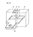
- FIG. 10 shows a perspective, schematic view of a further embodiment of an adapter plate 31, which in this case consists of two plate parts 32, 33, which can be snapped together using corresponding locking elements 34, 35.
- the individual flat plug with the molded contact springs, for example, the flat connector 22 are held firmly within the adapter plate 31, with the respective flat connector 22 being enclosed from all four sides, so that the intended flat connectors are extremely well fixed in position.
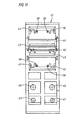
- FIGS. 11 and 12 show a further embodiment of an adapter plate 41 to be used in the context of the present invention, which in this case is designed such that it can be plugged onto the small relay 1 provided with flat plug connections 2, 22 from below.
- the individual tab connectors 2, 22 are completely surrounded by the adapter plate 41, so that excellent insulation of the individual tabs 2, 22 is achieved.
- Z-shaped guide grooves or guide slots are also provided, in which the two outer flat plugs 2 come to lie.
- the entry points of these guide grooves are designated 45.
- latching lugs 42 are provided on both sides in the region of the guide grooves, which, when the adapter plate 41 is slid onto the tabs 2, 22, correspond to the tabs 22, 2 on the side g e-seen recesses snap into place.
- the adapter plate 41 is provided in the region of the Z-shaped guide grooves with additional point supports 50, on which the angled regions of the flat connectors 2 come to rest, resulting in a exact positioning of this tab 2 comes in relation to the adapter plate 41.
- the adapter plate 41 shown in FIGS. 11 and 12 has through openings 47 and 48 arranged in pairs in its lower region, the through openings 47 serving to lead the coil connections through and the through openings 48 serving to lead the end connections through.
- the adapter plate 41 is additionally provided with ribs 49 and a latching tab 51, the ribs 49 serving to enlarge the crawling plugs resulting between the individual tabs 2, 22, while the latching tab 11 fastens the adapter plate 41 with the small relay 1 placed thereon allowed within electrical equipment.
Landscapes
- Physics & Mathematics (AREA)
- Electromagnetism (AREA)
- Connector Housings Or Holding Contact Members (AREA)
- Coupling Device And Connection With Printed Circuit (AREA)
Abstract
Die vorliegende Erfindung bezieht sich auf ein Relais, insbesondere Kleinstrelais, mit einem der Halterung der Magnetspule und des Kontaktfedersatzes dienenden Federbock.The present invention relates to a relay, in particular a small relay, with a spring bracket which serves to hold the magnetic coil and the contact spring set.
Im Hinblick auf einen möglichst einfachen Aufbau eines derartigen Relais ist im Rahmen der vorliegenden Erfindung vorgesehen, daß die einzelnen Kontaktfedern des Kontaktfedersatzes nach unten hin mit einstückig angeformten Flachsteckern versehen sind, welche durch in der Bodenwandung des Federbockes angeordnete Schlitze hindurchgeführt und in diesem Bereich sowohl kraftwie auch formschlüssig positionsmäßig fixiert sind.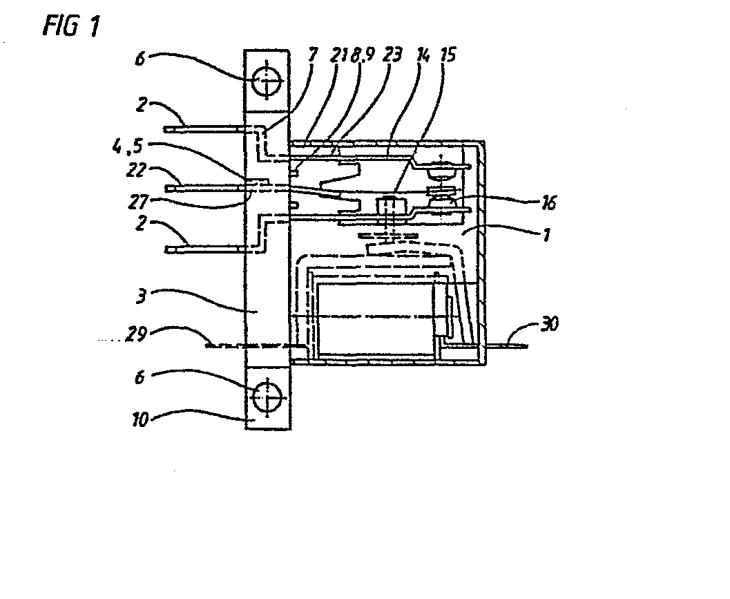
Description
Die vorliegende Erfindung bezieht sich auf ein Relais, insbesondere Kleinstrelais, mit einem der Halterung der Magnetspule und des Kontaktfedersatzes dienenden Federbock.The present invention relates to a relay, in particular a small relay, with a spring bracket which serves to hold the magnetic coil and the contact spring set.
Relais werden heutzutage vielfach mit Flachsteckeranschlüssen versehen, aufgrund welcher Maßnahme es möglich ist, derartige Relais in sehr einfacher Weise in bereits vorhandene elektrische Schaltungen einzusetzen, bzw. im Fall einer Störung austauschen zu können.Nowadays, relays are often provided with flat plug connections, on the basis of which measure it is possible to use such relays in a very simple manner in existing electrical circuits, or to be able to replace them in the event of a fault.
Bei derartigen, mit Flachsteckeranschlüssen versehenen Relais erfolgt die Verbindung der einzelnen Flachstecker mit den Anschlüssen des Kontaktfedersatzes mit Hilfe innerhalb des Relais angeordneter Leiter, welche an den Anschlüssen der Flachstecker und des Kontaktfedersatzes beispielsweise durch Anlöten befestigt werden müssen.In such relays provided with flat plug connections, the individual flat plugs are connected to the connections of the contact spring set with the aid of conductors arranged inside the relay, which have to be fastened to the connections of the flat plug and the contact spring set, for example by soldering.
Im Hinblick auf diesen Stand der Technik ist es Aufgabe der vorliegenden Erfindung, ein Relais, insbesondere Kleinstrelais zu schaffen, welches im Hinblick auf die vorhandenen, getrennten räumlichen Verhältnisse einen stark vereinfachten Aufbau besitzt - in dem auf das Vorsehen getrennt innerhalb des Relais zu verlegender Verbindungsleiter verzichtet werden kann.In view of this prior art, it is an object of the present invention to provide a relay, in particular a small relay, which has a greatly simplified structure in view of the existing, separate spatial conditions - in the connecting conductor to be routed separately within the relay can be dispensed with.
Erfindungsgemäß wird dies dadurch erreicht, daß die einzelnen Kontaktfedern des Kontaktfedersatzes nach unten hin 5 mit einstückig angeformten Flachsteckern versehen sind, welche durch in der Bodenwandung des Federbockes angeordnete Schlitze hinduchgeführt und in diesem Bereich sowohl kraft- wie auch formschlüssig positionsmäßig fixiert sind.According to the invention, this is achieved in that the individual contact springs of the
Vorteilhafte Weiterbildungen der Erfindung ergeben sich anhand der Unteransprüche.Advantageous developments of the invention result from the subclaims.
Die vorliegende Erfindung basiert auf der Erkenntnis, daß der vorgesehene Kontaktfedersatz des betreffenden Relais derart modifiziert werden kann, daß die im Normalfall im Innern des jeweiligen Relais vorgesehenen Leitungsanschlüsse des Kontaktfedersatzes auf der Außenseite des Relais zu liegen gelangen, in welchem Fall die betreffenden Leitungsanschlüsse unmittelbar in Form von Flachsteckeranschlüssen ausgebildet werden können, so daß auf das Vorsehen von innerhalb des Relais angeordneter, getrennt zu verlegender Verbindungsleiter verzichtet werden kann. Die Positionsfixierung des Kontaktfedersatzes mit den einstückig angeformten Flachsteckern erfolgt dabei zweckmäßigerweise innerhalb einer Adapterplatte, welcher unter Einsatz vonRippen und Nuten an der Bodenwandung des Federbockes des betreffenden Relais befestigbar ist. Die vorgesehene Adapterplatte muß dabei derart ausgebildet sein, daß mit Hilfe desselben sowohl die auf der Außenseite des Relais zu liegen gelangenden Flachstecker, wie auch die auf der Innenseite des Relais angeordneten Kontaktfedern positionsmäßig fixiert sind. Die positionsmäßige Fixierung dieser Elemente kann dabei entweder durch Umspritzen, Festkleben oder seitliches Aufschieben des mit den Flachsteckern versehenen Kontaktfedersatzes in innerhalb der Adapterplatte vorgesehene Schlitze erfolgen.The present invention is based on the knowledge that the intended contact spring set of the relay in question can be modified such that the line connections of the contact spring set provided in the interior of the respective relay normally come to lie on the outside of the relay, in which case the relevant line connections directly in Form of flat plug connections can be formed, so that the provision of arranged within the relay, separately to be laid connecting conductors can be dispensed with. The position of the contact spring set with the one-piece molded flat plugs is expediently carried out within an adapter plate, which can be fastened to the bottom wall of the spring bracket of the relay in question using ribs and grooves. The adapter plate provided must be designed in such a way that both the tabs to be located on the outside of the relay and the contact springs arranged on the inside of the relay are fixed in position with the aid of the same. The positional fixation of these elements can take place either by extrusion coating, gluing or laterally pushing on the contact spring set provided with the flat plugs into slots provided within the adapter plate.
Die innerhalb der Adapterplatte vorgesehenen Schlitze bzw. Führungsnuten sind dabei zweckmäßigerweise Z-förmig ausgelegt, wodurch einerseits eine gute positionsmäßige Arretierung der einzelnen Kontaktfedern mit ihren Flachsteckern zustande kommt, während andererseits unter Aufrechterhaltung eines relativ geringen, gegenseitigen Abstandes der einzelnen Kontaktfedern der gegenseitige Abstand zwischen den einzelnen Flachsteckern vergrößert wird, was im Hinblick auf die erforderlichen Isolationseigenschaften vielfach wünschenswert bzw. erforderlich erscheint. Zur weiteren Vergrößerung der vorhandenen Kriechsteckern besteht fernerhin die Möglichkeit, daß auf der Außenseite der Adapterplatte zusätzliche Rippen oder Nuten vorgesehen sind, welche zwischen den einzelnen Flachsteckern verlaufen. Die vorgesehene Adapterplatte ist schließlich noch derart ausgebildet, daß unter Einsatz der vorgesehenen Adapterplatte die Befestigung des Relais innerhalb einer elektrischen Schaltung möglich ist.The slots or guide grooves provided within the adapter plate are expediently designed in a Z-shape, which on the one hand ensures a good position Locking of the individual contact springs with their tabs comes about, while on the other hand the mutual distance between the individual tabs is increased while maintaining a relatively small mutual distance between the individual tabs, which often appears desirable or necessary in view of the required insulation properties. To further enlarge the existing crawling plugs, there is also the possibility that additional ribs or grooves are provided on the outside of the adapter plate, which run between the individual flat plugs. The provided adapter plate is finally designed such that the relay can be attached within an electrical circuit using the provided adapter plate.
Die Erfindung soll nunmehr anhand von Ausführungsbeispielen näher beschrieben und erläutert werden, wobei auf die beigefügte Zeichnung Bezug genommen ist.The invention will now be described and explained in more detail with reference to exemplary embodiments, reference being made to the accompanying drawing.
Es zeigen:
- Fig. 1 eine seitliche Ansicht, teilweise im Schnitt einer ersten Ausführungsform des erfindungsgemäßen Kleinstrelais,
Figuren 2 und 3 jeweils eine Seiten- und Stirnansicht des Kleinstrelais von Fig. 1,- Figuren 4 bis 6 verschiedene Ansichten der Adapterplatte des Kleinstrelais von Fig. 1,
Figuren 7 bis 9 schematische Schnittansichten, abgewandelte Ausführungsformen von Adapterplatten mit den von ihnen getragenen Federkontaktsätzen,- Fig. 10 eine schematische, perspektivische Ansicht einer abgewandelten Ausführungsform einer Adapterplatte für die Halterung eines Federkontaktsatzes und
Figuren 11 und 12 eine Draufsicht bzw. seitliche Ansicht einer weiteren Ausführungsform einer Adapterplatte zur Halterung bzw. Positionierung eines Federkontaktsatzes.
- 1 is a side view, partly in section, of a first embodiment of the small relay according to the invention,
- FIGS. 2 and 3 each show a side and end view of the small relay from FIG. 1,
- FIGS. 4 to 6 show different views of the adapter plate of the small relay from FIG. 1,
- FIGS. 7 to 9 are schematic sectional views, modified embodiments of adapter plates with the spring contact sets carried by them,
- Fig. 10 is a schematic, perspective view of a modified embodiment of an adapter plate for holding a spring contact set and
- FIGS. 11 and 12 show a top view or side view of a further embodiment of an adapter plate for holding or positioning a spring contact set.
Das in den Figuren 1 - 3 gezeigte Kleinstrelais 1 enthält ein Antriebssystem, dessen Spule über Spulenanschlüsse 29, 30 ansteuerbar ist. Der Anker wirkt dabei auf einen Kontaktfedersatz, welcher aus drei Kontaktfedern 14 bis 16 besteht. Diese Kontaktfedern 14 bis 16 sind dabei einstückig mit aus der Bodenfläche des Relais ragenden Flachsteckern 2, 22 ausgebildet. Die Kontaktfedern 14 bis 16 führen dabei durch Schlitze 23 eines Federbocks 21 hindurch und sind von geraden bzw. Z-förmig ausgebildeten Schlitzen 7, 27 einer Adapterplatte 3 positionsmäßig fixiert. Die Adapterplatte 3 dient dabei dazu, daß die auf die Flachstecker 2, 22 einwirkenden Steckkräfte nicht auf den Federbock 3 und damit auf die Kontaktfedern 14 bis 16 übertragen werden können. Dies wird dadurch erreicht, daß beispielsweise an dem mittleren Flachstecker 22 ein vorstehender Lappen 4 vorgesehen ist, welcher in eine entsprechende Rastöffnung 5 im Bereich der Führungsnut 27 zum Einrasten gelangt. Die Positionierung der beiden äußeren Kontaktfedern 14, 16 erfolgt hingegen dadurch, daß die entsprechende Federungsnut 7 der Adapterplatte 3 sowie die darin zu liegen gelangenden Flachstecker 2 Z-förmig ausgebildet sind, so daß auf diese Weise eine gute Halterung zustande kommt.The
Die Adapterplatte 3 ist in senkrechter Ebene zur Zeichenebene der Figur 1 auf dem Federbock 21 des Kleinstrelais 1 aufschiebbar. Zur formschlüssigen Verbindung der Adapterplatte 3 mit der Bodenfläche des Federbocks 21 ist vorgesehen, daß an der der Bodenfläche zugewandten Seite der Adapterplatte 3 abragende Rippen vorhanden sind, die in entsprechende Nuten 3 an der Bodenfläche des Federbocks 21 zum Eingreifen gelangen. An den beiden Enden der Adapterplatte 3 sind zusätzlich Ansätze 10 mit Bohrungen 6 vorgesehen, durch welche nicht gezeigte Befestigungs- mittel hindurchführen, mit denen die Adapterplatte 3 auf einer beliebigen Befestigungsfläche befestigt werden kann.The
Die Figuren 4 bis 6 zeigen weitere Einzelheiten der Adapterplatte 3. Anhand dieser Figuren ist erkennbar, daß die als Führungsnuten 7 wirkenden Schlitze Z-förmig ausgebildet sind, während die Führungsnut 27 gerade ausgelegt ist. Im Bereich der Federungsnut 7, 27 ist jeweils eine Rastöffnung 5 vorgesehen, in welcher der jeweilige Flachstecker 2, 22 mit davon abragenden Lappen 4 zum Einrasten gelangt.Figures 4 to 6 show further details of the
Figur 7 zeigt in schematischer, vergrößerter Darstellung die Art der Befestigung der Adapterplatte 3 auf den mit Flachsteckern 2, 22 versehen Kontaktfedern 14 bis 16. Anhand dieser Figur sind die an der Rückseite der Adapterplatte 3 vorstehenden Rippen 8 erkennbar, welche in entsprechenden Nuten 9 im Bereich des Federbocks 11 des Relais 1 zum Eingreifen gelangen. Hieraus wird deutlich, daß die Kontaktfedern 14 bis 16 jederzeit wieder aus den Schlitzen 23 des Federbocks 11 herausziehbar und gegen Kontaktfedern anderer Art ersetzbar sind.FIG. 7 shows a schematic, enlarged representation of the type of attachment of the
Bei der in Figur 8 gezeigten Ausführungsform weist die Adapterplatte 13 auf der einen Seite Nuten 13 auf, deren Längserstreckung parallel zur Breitseite der Flachstecker 2, 22 verläuft, so daß zwischen den Flachsteckern Kriechsteckern vergrößerter Länge ausgebildet sind. Gegenüberliegend zu den Nuten 18 sind im Material der Adapterplatte 13 Rippen 17 ausgeformt, welche in die nicht näher dargestellten Nuten im Federbock des Relais 1 eingreifen. Bei dieser Ausführungsform sind ferner die Kontaktfedern 14 - 16 mit ihren Flachsteckern 2, 22 in das Material der Adapterplatte 13 eingespritzt, d.h. also unlösbar mit der Adapterplatte 13 verbunden. Anstelle des Einbettens im KunststoffmateriaL der Adapterplatte 13 kann die Befestigung der Kontaktfedern 14 bis 16 mit ihre Flachsteckern 2, 22 ebenfalls curch Einkleben erfolgen.In the embodiment shown in FIG. 8, the
Bei der Ausführungsform nach Figur 9 ist eine Adapterplatte 19 vorgesehen, bei welcher die mittlere Führungsnut 27 dadurch axial verlängert ausgebildet ist, daß sie im Bereich einer keilförmig ausgebildeten Abstützung 20 der Adapterplatte 19 mündet. Es ist fernerhin erkennbar, daß die äußeren Kontaktfedern 14 und 16 mit Lappen 12 versehen sind, welche im Material des Federbocks 21 zum Einrasten gelangen. Hierdurch wird eine zusätzliche Lagensicherung der Kontaktfedern 14 - 16 im Bereich der Schlitze 23 gewährleistet.In the embodiment according to FIG. 9, an
Figur 10 zeigt in perspektivischer, schematischer Ansicht eine weitere Ausführungsform einer Adapterplatte 31, welche in diesem Fall aus zwei Plattenteilen 32, 33 besteht, die unter Einsatz entsprechender Rastelemente 34, 35 zusammenschnappend miteinander verbindbar sind.FIG. 10 shows a perspective, schematic view of a further embodiment of an adapter plate 31, which in this case consists of two
Mit Hilfe dieser aus den beiden Plattenteilen 32, 33 bestehenden Adapterplatten 31 können die einzelnen Flachstecker mit den daran angeformten Kontaktfedern beispielsweise der Flachstecker 22 fest innerhalb der Adapterplatte 31 gehalten werden, wobei eine Umschließung des betreffenden Flachsteckers 22 von allen vier Seiten her erfolgt, so daß auf diese Weise die vorgesehenen Flachstecker positionsmäßig äußerst gut fixiert sind.With the help of these consisting of the two
Figuren 11 und 12 zeigen eine weitere Ausführungsform einer im Rahmen der vorliegenden Erfindung zu verwendenden Adapterplatte 41, welche in diesem Fall derart ausgebildet ist, daß diese von unten her auf das mit Flachsteckeranschlüssen 2, 22 versehene Kleinstrelais 1 aufgesteckt werden kann. Die einzelnen Flachsteckeranschlüsse 2, 22 werden dabei von der Adapterplatte 41 vollständig umfaßt, so daß eine ausgezeichnete Isolierung der einzelnen Flachstecker 2, 22 zustande kormt. Bei der betreffenden Adapterplatte 41 sind in Übereinstimmung mit der Ausführungsform in Figur 1 ebenfalls Z-förmige Führungsnuten bzw. Führungsschlitze vorgesehen, in welchen die beiden äußeren Flachstecker 2 zu liegen gelangen. In Figur 12 sind dabei die Eintrittsstellen dieser Führungsnuten mit 45 bezeichnet.FIGS. 11 and 12 show a further embodiment of an
Um eine gute positionsmäßige Fixierung der einzelnen Flachstecker 22, 22 innerhalb der Adapterplatte 41 zu erreichen, sind im Bereich der Führungsnuten beidseitig Rastnasen 42 vorgesehen, welche beim Aufschieben der Adapterplatte 41 auf die Flachstecker 2, 22 in entsprechenden seitlich an den Flachsteckern 22, 2 vorge-sehenen Ausnehmungen zum Einrasten gelangen.In order to achieve a good positional fixation of the
Die Adapterplatte 41 ist im Bereich der Z-förmigen Führungsnuten mit zusätzlichen Punktauflagen 50 versehen, auf welchen die abgewinkelten Bereiche der Flachstecker 2 zum Aufliegen gelangen, wobei es zu einer genauen Positionierung dieser Flachstecker 2 in Bezug auf die Adapterplatte 41 kommt.The
Die in den Figuren 11 und 12 dargestellte Adapterplatte 41 weist in ihrem unteren Bereich paarig angeordnete Durchtrittsöffnungen 47 und 48 auf, wobei die Furchtrittsöffnungen 47 zum Hindurchführen der Spulenanschlüsse und die Durchtrittsöffnungen 48 zum Hindurchführen der Endungsanschlüsse dienen.The
Die Adapterplatte 41 ist schließlich zusätzlich noch mit Rippen 49 und einem Rastlappen 51 versehen, wobei die Rippen 49 der Vergrößerung der zwischen den einzelnen Flachsteckern 2, 22 sich ergebenden Kriechsteckern dienen, während der Rastlappen 11 eine Befestigung der Adapterplatte 41 mit dem darauf aufgesetzten Kleinstrelais 1 innerhalb einer elektrischen Gerätschaft erlaubt.Finally, the
-
5. Relais nach Anspruch 2, dadurch
gekennzeichnet, daß die Adapterplatte (31)
aus zwei in Längsrichtung verlaufenden, gegeneinander verriegelbaren, Plattenteilen (32, 33) besteht, welche von beiden Seiten her auf die Flachstecker (2, 22) der Kontaktfedern (14 bis 16) schiebbar sind, (Fig. 10).5. Relay according toclaim 2, characterized
characterized in that the adapter plate (31)
consists of two longitudinally extending, mutually lockable, plate parts (32, 33) which can be pushed from both sides onto the tabs (2, 22) of the contact springs (14 to 16) (Fig. 10). -
6. Relais nach einem der Ansprüche 3 bis 5,
dadurch gekennzeichnet, daß die
Flachstecker, insbesondere die beiden äußeren Flachstecker (2), Z-förmig gebogen sind und daß die Führungsnuten (7) der Adapterplatte (3) für die Aufnahme dieser Flachstecker (2) entsprechend geformt sind, (Fig. 1).6. Relay according to one ofclaims 3 to 5,
characterized in that the
Flat plugs, in particular the two outer flat plugs (2), are bent in a Z-shape and that the guide grooves (7) of the adapter plate (3) for receiving these flat plugs (2) are shaped accordingly (FIG. 1). -
7. Relais nach einem der Ansprüche 3 bis 5,
dadurch gekennzeichnet, daß die
Flachstecker, insbesondere der mittlere Flachstecker (22), im wesentlichen gerade ausgelegt ist, in welchem Fall die Positionsfixierung gegenüber der Adapterplatte (3, 19) durch Vorsehen eines verrastbaren Lappens (4), einer geringfügigen Abwinklung oder einer vorspringenden Abstützung (20) der Adapterplatte (19) bewirkt ist, (Figur 1, 7, 9).7. Relay according to one ofclaims 3 to 5,
characterized in that the
Flat plug, in particular the middle flat plug (22), is designed essentially straight, in which case the position fixing relative to the adapter plate (3, 19) is provided by providing a latchable tab (4), a slight angling or a protruding support (20) of the adapter plate (19) is effected (Figure 1, 7, 9). -
8. Relais nach einem der vorhergehenden Ansprüche
dadurch gekennzeichnet, daß
die Adapterplatte (3, 19) durch Vorsehen von entsprechenden Rippen (8, 17) bzw. Nuten (19) an der Bodenwandung des Federbockes (11, 21) befestigbar ist.8. Relay according to one of the preceding claims
characterized in that
the adapter plate (3, 19) can be fastened to the bottom wall of the spring bracket (11, 21) by providing corresponding ribs (8, 17) or grooves (19). -
9. Relais nach einem der vorhergehenden Ansprüche,
dadurch gekennzeichnet , daß auf
der Außenseite der Adapterplatte (13) zusätzliche Rippen oder Nuten (18) vorgesehen sind, welche der Vergrößerung der Kriechstrecken zwischen den einzelnen Flachsteckern (2, 22) dienen (Fig. 8).9. Relay according to one of the preceding claims,
characterized in that on
the outside of the adapter plate (13) additional ribs or grooves (18) are provided, which serve to increase the creepage distances between the individual tabs (2, 22) (Fig. 8).
Claims (46)
gekennzeichnet, daß die einzelnen Kontaktfedern (14 bis 16) des Kontaktfedersatzes nach unten hin mit einstückig angeformten Flachsteckern (2, 22) versehen sind, welche durch in der Bodenwandung des Federbocks (11, 21) angeordnete Schlitze (23) hindurchgeführt und in diesem Bereich sowohl kraft- wie auch formschlüssig fixiert sind.1. Relay, in particular small relay, with a spring bracket that serves to hold the magnetic coil and the contact spring set, thereby
characterized in that the individual contact springs (14 to 16) of the contact spring set are provided at the bottom with integrally molded flat plugs (2, 22) which pass through slots (23) arranged in the bottom wall of the spring bracket (11, 21) and in this area are fixed both positively and positively.
gekennzeichnet, daß parallel zu der Bodenwandung des Federbockes (11, 21) eine an demselben formschlüssig befestigte mit Führungsnuten (7, 27, 45) versehene Adapterplatte (3, 13, 19, 31, 41) vorgesehen ist, welche der kraft- und formschlüssigen Positionierung der einstückig an den Kontaktfedern (14 bis 16) angesetzten Flachstecker (2, 22) dient.2. Relay according to claim 1, characterized
characterized in that parallel to the bottom wall of the spring bracket (11, 21) there is provided an adapter plate (3, 13, 19, 31, 41) which is positively fastened to it and provided with guide grooves (7, 27, 45) and which is of positive and positive locking Positioning of the flat plug (2, 22) attached to the contact springs (14 to 16) is used.
gekennzeichnet, daß die einstückig an den Kontaktfedern (14 bis 16) angesetzten Flachstecker (2, 22) in der Adapterplatte (13) durch Umspritzen befestigt sind, (Fig. 8).3. Relay according to claim 2, characterized
characterized in that the tabs (2, 22) attached in one piece to the contact springs (14 to 16) are fastened in the adapter plate (13) by extrusion coating, (FIG. 8).
gekennzeichnet, daß die in der Adapterplatte (3) vorgesehenen Führungsschlitze (7, 27) einseitig offen sind, demzufolge die Flachstecker (2, 22) mit den daran angeformten Kontaktfedern (14 bis 16) von der Seite her in die Adapterplatte 3 einschiebbar sind, (Fig. 1).4. Relay according to claim 2, characterized
characterized in that the guide slots (7, 27) provided in the adapter plate (3) are open on one side, consequently the tabs (2, 22) with the contact springs (14 to 16) formed thereon can be inserted into the adapter plate 3 from the side, (Fig. 1).
dadurch gekennzeichnet, daß die Adapterplatte (3) im Bereich ihrer beiden Enden mit Bohrungen (6) versehene Ansätze (10) aufweist, welche der Befestigung des betreffenden Relais dienen, (Fig. 1,7).10. Relay according to one of the preceding claims,
characterized in that the adapter plate (3) has in the region of its two ends with bores (6) provided lugs (10) which serve to fasten the relay in question, (Fig. 1.7).
Applications Claiming Priority (2)
| Application Number | Priority Date | Filing Date | Title |
|---|---|---|---|
| DE3319927 | 1983-06-01 | ||
| DE3319927 | 1983-06-01 |
Publications (3)
| Publication Number | Publication Date |
|---|---|
| EP0127849A2 true EP0127849A2 (en) | 1984-12-12 |
| EP0127849A3 EP0127849A3 (en) | 1985-08-21 |
| EP0127849B1 EP0127849B1 (en) | 1988-11-02 |
Family
ID=6200471
Family Applications (1)
| Application Number | Title | Priority Date | Filing Date |
|---|---|---|---|
| EP84105922A Expired EP0127849B1 (en) | 1983-06-01 | 1984-05-24 | Relay |
Country Status (3)
| Country | Link |
|---|---|
| US (1) | US4571567A (en) |
| EP (1) | EP0127849B1 (en) |
| DE (1) | DE3475026D1 (en) |
Cited By (3)
| Publication number | Priority date | Publication date | Assignee | Title |
|---|---|---|---|---|
| DE3544533A1 (en) * | 1985-12-17 | 1987-06-19 | Hengstler Gmbh | Relay with installation-simplifying retention on a board |
| EP0262433A1 (en) * | 1986-09-06 | 1988-04-06 | Alcatel SEL Aktiengesellschaft | Relay, particularly miniature relay |
| DE19956498A1 (en) * | 1999-11-24 | 2001-08-23 | Tyco Electronics Logistics Ag | Arrangement of relay with adapter base, has leadthroughs in adapter base for relay connector elements fed through to connector side, and base connector elements on connector side of adapter base |
Families Citing this family (3)
| Publication number | Priority date | Publication date | Assignee | Title |
|---|---|---|---|---|
| EP0189921B1 (en) * | 1985-01-31 | 1989-08-02 | Nec Corporation | Electromagnetic relay |
| US4761627A (en) * | 1987-09-17 | 1988-08-02 | Potter And Brumfield Inc. | Electromagnetic relay including a rotatable armature mount |
| FR3082353B1 (en) | 2018-06-08 | 2022-11-04 | Langlade & Picard | MOBILE SWITCHING DEVICE (F) FOR MONOSTABLE LOW-VOLTAGE ELECTROMAGNETIC RELAY (BETWEEN 110V AND 400V) |
Family Cites Families (12)
| Publication number | Priority date | Publication date | Assignee | Title |
|---|---|---|---|---|
| DE1867986U (en) * | 1962-10-26 | 1963-02-28 | Haller & Co E | PLUG-IN SOCKET FOR SMALL RELAY. |
| US3230296A (en) * | 1963-01-23 | 1966-01-18 | S H Couch Company Inc | Contact terminal assembly with different geometric configured contacts on either side of a plate |
| FR1481910A (en) * | 1963-02-08 | 1967-05-26 | Bernier & Co | System for fixing the contact blades and connection blades on the cylinder head of an electromagnetic relay, and electromagnetic relay fitted with such a system |
| GB1308770A (en) * | 1970-05-26 | 1973-03-07 | Omron Tateisi Electronics Co | Electromagnetic relays |
| DE2058864A1 (en) * | 1970-11-30 | 1972-05-31 | Siemens Ag | Contact spring set |
| JPS538901B2 (en) * | 1971-09-01 | 1978-04-01 | ||
| FR2252642A1 (en) * | 1973-11-28 | 1975-06-20 | Seima | Electromagnetic relay with sprung contact - magnetic circuit is formed from a support which form a pins connection |
| US3878489A (en) * | 1974-03-28 | 1975-04-15 | Square D Co | Electromagnetic relay having a printed circuit board connection between the contacts and radio type plug-in connector |
| DK139405C (en) * | 1974-10-28 | 1979-07-16 | Danfoss As | KLAPANKERRELAE |
| CH600543A5 (en) * | 1975-12-08 | 1978-06-15 | Elesta Ag Elektronik | |
| DE2833153A1 (en) * | 1978-07-28 | 1980-02-14 | Bosch Gmbh Robert | ELECTROMAGNETIC RELAY |
| AT386696B (en) * | 1980-12-03 | 1988-09-26 | Schrack Elektronik Ag | CONTACT SPRING SET |
-
1984
- 1984-05-24 DE DE8484105922T patent/DE3475026D1/en not_active Expired
- 1984-05-24 EP EP84105922A patent/EP0127849B1/en not_active Expired
- 1984-05-29 US US06/614,535 patent/US4571567A/en not_active Expired - Fee Related
Cited By (5)
| Publication number | Priority date | Publication date | Assignee | Title |
|---|---|---|---|---|
| DE3544533A1 (en) * | 1985-12-17 | 1987-06-19 | Hengstler Gmbh | Relay with installation-simplifying retention on a board |
| EP0262433A1 (en) * | 1986-09-06 | 1988-04-06 | Alcatel SEL Aktiengesellschaft | Relay, particularly miniature relay |
| US4827232A (en) * | 1986-09-06 | 1989-05-02 | Alcatel N.V. | Relay, particularly miniature relay |
| DE19956498A1 (en) * | 1999-11-24 | 2001-08-23 | Tyco Electronics Logistics Ag | Arrangement of relay with adapter base, has leadthroughs in adapter base for relay connector elements fed through to connector side, and base connector elements on connector side of adapter base |
| DE19956498C2 (en) * | 1999-11-24 | 2002-08-14 | Tyco Electronics Logistics Ag | Arrangement of a relay with an adapter base |
Also Published As
| Publication number | Publication date |
|---|---|
| US4571567A (en) | 1986-02-18 |
| DE3475026D1 (en) | 1988-12-08 |
| EP0127849B1 (en) | 1988-11-02 |
| EP0127849A3 (en) | 1985-08-21 |
Similar Documents
| Publication | Publication Date | Title |
|---|---|---|
| DE602005000149T2 (en) | Connection arrangement of an electrical device | |
| EP0959529B1 (en) | Electrical connecting unit | |
| WO2017182033A1 (en) | Assembly for the touch-proof contacting of a bus bar system | |
| DE10150045B4 (en) | terminal block | |
| EP0127849A2 (en) | Relay | |
| DE9304929U1 (en) | Shielding device for rectangular cable connectors | |
| DE1933201A1 (en) | Device for the power transmission connection of electrical lines | |
| DE3433822A1 (en) | Connecting device | |
| DE2835952A1 (en) | ELECTRIC SUPPLY SYSTEM | |
| EP1149400A1 (en) | Electric device with a connection clip and a receiving fixture for a second electric device | |
| DE3827886C1 (en) | Contact element for an electrical plug connector | |
| DE69607136T2 (en) | Control panel and connection device for electrical installations with modular devices | |
| DE3414732C2 (en) | relay | |
| EP0477548A1 (en) | Connection device for weak current installations particularly for telecommunication and data communication | |
| DE29720511U1 (en) | Installation housing for printed circuit boards and electronic components | |
| DE3201169A1 (en) | DEVICE FOR CLAMPING THE ELECTRICAL LADDER, IN PARTICULAR WIRE | |
| EP0595304B1 (en) | Shielding device for a rectangular cable connector | |
| DE9113317U1 (en) | Junction box for electrical conductors of cables and/or cords for telecommunications technology | |
| EP0471199A1 (en) | Connection box for electrical conductors | |
| DE3925633C2 (en) | Device for firmly coupling at least two housings together | |
| DE3744190C2 (en) | Connection device for connecting a carrier plate to a daughter plate | |
| EP0303857B1 (en) | Support element | |
| DE2827143A1 (en) | Locking device for contacts of multipole connector - has contact with constriction engaged by spring arm on cover | |
| DE1690247A1 (en) | Plug connector for the electrical connection of several flat cable carriers | |
| DE69120641T2 (en) | Electrical plug with double insulation |
Legal Events
| Date | Code | Title | Description |
|---|---|---|---|
| PUAI | Public reference made under article 153(3) epc to a published international application that has entered the european phase |
Free format text: ORIGINAL CODE: 0009012 |
|
| AK | Designated contracting states |
Designated state(s): CH DE FR GB LI NL SE |
|
| PUAL | Search report despatched |
Free format text: ORIGINAL CODE: 0009013 |
|
| AK | Designated contracting states |
Designated state(s): CH DE FR GB LI NL SE |
|
| 17P | Request for examination filed |
Effective date: 19850824 |
|
| 17Q | First examination report despatched |
Effective date: 19861003 |
|
| GRAA | (expected) grant |
Free format text: ORIGINAL CODE: 0009210 |
|
| AK | Designated contracting states |
Kind code of ref document: B1 Designated state(s): CH DE FR GB LI NL SE |
|
| PG25 | Lapsed in a contracting state [announced via postgrant information from national office to epo] |
Ref country code: SE Effective date: 19881102 Ref country code: NL Effective date: 19881102 |
|
| REF | Corresponds to: |
Ref document number: 3475026 Country of ref document: DE Date of ref document: 19881208 |
|
| ET | Fr: translation filed | ||
| GBT | Gb: translation of ep patent filed (gb section 77(6)(a)/1977) | ||
| NLV1 | Nl: lapsed or annulled due to failure to fulfill the requirements of art. 29p and 29m of the patents act | ||
| PG25 | Lapsed in a contracting state [announced via postgrant information from national office to epo] |
Ref country code: GB Effective date: 19890524 |
|
| PG25 | Lapsed in a contracting state [announced via postgrant information from national office to epo] |
Ref country code: LI Free format text: LAPSE BECAUSE OF NON-PAYMENT OF DUE FEES Effective date: 19890531 Ref country code: CH Free format text: LAPSE BECAUSE OF NON-PAYMENT OF DUE FEES Effective date: 19890531 |
|
| PLBI | Opposition filed |
Free format text: ORIGINAL CODE: 0009260 |
|
| 26 | Opposition filed |
Opponent name: ALOIS ZETTLER ELEKTROTECHNISCHE FABRIK GMBH Effective date: 19890613 |
|
| GBPC | Gb: european patent ceased through non-payment of renewal fee | ||
| REG | Reference to a national code |
Ref country code: CH Ref legal event code: PL |
|
| RDAG | Patent revoked |
Free format text: ORIGINAL CODE: 0009271 |
|
| STAA | Information on the status of an ep patent application or granted ep patent |
Free format text: STATUS: PATENT REVOKED |
|
| REG | Reference to a national code |
Ref country code: FR Ref legal event code: ST |
|
| 27W | Patent revoked |
Effective date: 19891207 |
|
| GBPR | Gb: patent revoked under art. 102 of the ep convention designating the uk as contracting state |