EP0032300A1 - Fluid control system - Google Patents
Fluid control system Download PDFInfo
- Publication number
- EP0032300A1 EP0032300A1 EP80304547A EP80304547A EP0032300A1 EP 0032300 A1 EP0032300 A1 EP 0032300A1 EP 80304547 A EP80304547 A EP 80304547A EP 80304547 A EP80304547 A EP 80304547A EP 0032300 A1 EP0032300 A1 EP 0032300A1
- Authority
- EP
- European Patent Office
- Prior art keywords
- fluid
- check valve
- pump
- cylinder
- fluid conduit
- Prior art date
- Legal status (The legal status is an assumption and is not a legal conclusion. Google has not performed a legal analysis and makes no representation as to the accuracy of the status listed.)
- Withdrawn
Links
- 239000012530 fluid Substances 0.000 title claims description 56
Images

Classifications
-
- F—MECHANICAL ENGINEERING; LIGHTING; HEATING; WEAPONS; BLASTING
- F15—FLUID-PRESSURE ACTUATORS; HYDRAULICS OR PNEUMATICS IN GENERAL
- F15B—SYSTEMS ACTING BY MEANS OF FLUIDS IN GENERAL; FLUID-PRESSURE ACTUATORS, e.g. SERVOMOTORS; DETAILS OF FLUID-PRESSURE SYSTEMS, NOT OTHERWISE PROVIDED FOR
- F15B7/00—Systems in which the movement produced is definitely related to the output of a volumetric pump; Telemotors
- F15B7/005—With rotary or crank input
- F15B7/006—Rotary pump input
-
- F—MECHANICAL ENGINEERING; LIGHTING; HEATING; WEAPONS; BLASTING
- F15—FLUID-PRESSURE ACTUATORS; HYDRAULICS OR PNEUMATICS IN GENERAL
- F15B—SYSTEMS ACTING BY MEANS OF FLUIDS IN GENERAL; FLUID-PRESSURE ACTUATORS, e.g. SERVOMOTORS; DETAILS OF FLUID-PRESSURE SYSTEMS, NOT OTHERWISE PROVIDED FOR
- F15B2211/00—Circuits for servomotor systems
- F15B2211/20—Fluid pressure source, e.g. accumulator or variable axial piston pump
- F15B2211/205—Systems with pumps
- F15B2211/2053—Type of pump
- F15B2211/20561—Type of pump reversible
Definitions
- This invention relates to a fluid system for controlling the operating functions of a motor device, such as an actuator.
- a motor device such as an actuator.
- the invention is concerned with the provision of an improved hydraulic system for controlling the operating functions of the movable member of an actuator, for example, the piston of a double acting cylinder and piston unit.
- An object of the invention is to provide a fluid control system which includes a bi-rotational pump connected with the opposite ends of the cylinder of an actuator device so as to move the piston therein in one or the other direction in the cylinder depending on the selected direction of rotation of the pump..
- a further more specific object of the invention is to provide valving in the fluid control circuits so as to prevent back pressure from the cylinder driving the pump in the event of the application of an outside force to the piston rod.
- a still further object of the invention is to provide means for avoiding a hydraulic lock situation in the event that the output pressure from the pump drops below the back pressure from the cylinder of the actuator device.
- the invention provides a fluid system for controlling the operation of an actuator consisting of a cylinder containing a piston movable therein, the opposite ends of said cylinder being connected each with an opposite output of a bi-directional pump through a one-way pressure check valve preventing return flow of fluid from said one cylinder end to said pump, said system being further characterised in that each end of said cylinder is furthermore connected to a fluid reservoir through a check valve which is normally open to permit flow of fluid from said cylinder end to said reservoir but which is adapted to close in response to a predetermined increase in pressure between the corresponding pump output and its one-way pressure check valve.
- piston rod R is slidably movable in a double acting cylinder B, the ends of which are provided with ports B 1 , B 2 for the connection thereto of the hydraulic control system of the invention.
- the piston rod R extends from one end of the cylinder B and is connected to a device to be actuated such as a valve.
- the hydraulic control system comprises a pump C which is a bi-directional rotary gear pump with a high leakage rate across the gears.
- the pump is preferably rotated manually, but may be motor driven.
- the port B 1 at one end of the cylinder B is connected with one output C 1 of the pump C by a hydraulic line which includes a normally closed one-way pressure check valve D 1 .
- the valve D 1 is a relatively high crack pressure check valve operable, for example, at a pressure of about 401bs. per square inch.
- the hydraulic line between the port B 1 and check valve D 1 may further include a flow control valve A 1 which is adjustable to vary
- the actuator is a double acting, hydraulically operated cylinder and piston unit and flow control valves may be located in the circuit lines to the cylinder so as to provide a speed control for the movement of the piston.
- a piston P having a draws fluid from the reservoir G through one-way check valve F 2 which now opens and pressure fluid is then pumped at the output C of the pump.
- the outlet pressure of the fluid from the pump C closes check valve F 1 to the reservoir G and when the pressure reaches approximately one half the crack pressure of the check valve D 1 , the pressure also communicated to valve E 1 closes the valve E 1 so isolating the corresponding end of cylinder B from the reservoir G.
- the valve D 1 opens at its rated pressure and the pressure then builds up in the corresponding right hand end of cylinder B. At this time fluid in the left hand end of cylinder B is able to travel freely from the cylinder via port B 2 to the reservoir G through the open check valve-E 2 so that the piston P will move to the left and retract the piston rod R.
- the system works in a similar manner to extend the piston rod R from the cylinder the speed of operation of the system, and the line is additionally connected to the reservoir G through a normally open pilot operated check valve E 1 .
- the hydraulic line between the pressure check valve D 1 and pump output C 1 is connected firstly, with the reservoir G through a one-way check valve F 1 ; and secondly, with the check valve B 1 on that side of the check valve remote from the reservoir.
- the hydraulic control system of the invention is completed by similar hydraulic connections and valves between the port B 2 at the other end of the cylinder B and the other outlet C 2 of the pump, the various valves being given the corresponding reference letters with the suscript 2.
- the hydraulic system as shown in Figure '1 is in an inoperative position.
- the pump has been manually operated to energize the pump C so that it rotates clockwise in the direction of the arrow.
- the pump C when the pump C is operated in the opposite anti-clockwise direction.
- Speed control of the system may be obtained by adjustment of the flow control valves A 1 and A 2 .
- the check valves D 1 , D 2 prevent the fluid from reaching the pump C and thereby driving it as a motor.
- Manual operation of the pump C in this situation could produce enough pressure in the pilot valve line to keep the pilot operated normally open check valves E 11 E 2 in a closed position thus causing a hydraulic lock.
- the control system of the invention avoids this problem due to the fact that upon cessation of manual operation of the pump handle, the pressure drop due to leakage across the pump is sufficiently high to cause an instantaneous opening of the pilot operated check valves E 1' E 2 so that a hydraulic lock is avoided.
- the one-way check valves D 1 and D 2 may be each combined as a single, unitary valve structure with its corresponding check valve E 1 and E 2 .
- the single valve structure may comprise a ported valve having a valve member which is slidably movable in response to the pump pressure firstly to isolate the reservoir drain line and secondly to open the line between the pump and the corresponding end of the cylinder.
- the actuator may be of the rotary vane type, the movable piston member in such an arrangement comprising a vane angularly movable in a quadrant-shaped cylinder through an arc of approximately 90°
Landscapes
- Engineering & Computer Science (AREA)
- Physics & Mathematics (AREA)
- Fluid Mechanics (AREA)
- Mechanical Engineering (AREA)
- General Engineering & Computer Science (AREA)
- Fluid-Pressure Circuits (AREA)
Abstract
The invention relates to a hydraulic system for the control of an actuator consisting of a double acting cylinder and piston unit. The control system comprises a bi-directional pump C the opposite outlets C1 and C2 of which are connected respectively with the opposite ends of the cylinder B through a one-way pressure check valve D1. Each end of the cylinder is also connected with a hydraulic reservoir G through a check valve E1 which is also connected with the respective pump outlet C, so as to close in response to a predetermined increase in the hydraulic pressure between the pump outlet C1 and its respective one-way pressure check valve D1.
Description
- This invention relates to a fluid system for controlling the operating functions of a motor device, such as an actuator. In particular, but not exclusively, the invention is concerned with the provision of an improved hydraulic system for controlling the operating functions of the movable member of an actuator, for example, the piston of a double acting cylinder and piston unit.
- An object of the invention is to provide a fluid control system which includes a bi-rotational pump connected with the opposite ends of the cylinder of an actuator device so as to move the piston therein in one or the other direction in the cylinder depending on the selected direction of rotation of the pump.. A further more specific object of the invention is to provide valving in the fluid control circuits so as to prevent back pressure from the cylinder driving the pump in the event of the application of an outside force to the piston rod. A still further object of the invention is to provide means for avoiding a hydraulic lock situation in the event that the output pressure from the pump drops below the back pressure from the cylinder of the actuator device.
- In its broadest aspect the invention provides a fluid system for controlling the operation of an actuator consisting of a cylinder containing a piston movable therein, the opposite ends of said cylinder being connected each with an opposite output of a bi-directional pump through a one-way pressure check valve preventing return flow of fluid from said one cylinder end to said pump, said system being further characterised in that each end of said cylinder is furthermore connected to a fluid reservoir through a check valve which is normally open to permit flow of fluid from said cylinder end to said reservoir but which is adapted to close in response to a predetermined increase in pressure between the corresponding pump output and its one-way pressure check valve.
- piston rod R is slidably movable in a double acting cylinder B, the ends of which are provided with ports B1, B2 for the connection thereto of the hydraulic control system of the invention. The piston rod R extends from one end of the cylinder B and is connected to a device to be actuated such as a valve.
- The hydraulic control system comprises a pump C which is a bi-directional rotary gear pump with a high leakage rate across the gears. The pump is preferably rotated manually, but may be motor driven. The port B1 at one end of the cylinder B is connected with one output C1 of the pump C by a hydraulic line which includes a normally closed one-way pressure check valve D1. The valve D1 is a relatively high crack pressure check valve operable, for example, at a pressure of about 401bs. per square inch.
- The hydraulic line between the port B1 and check valve D1 may further include a flow control valve A1 which is adjustable to vary
- In the preferred embodiment of the invention the actuator is a double acting, hydraulically operated cylinder and piston unit and flow control valves may be located in the circuit lines to the cylinder so as to provide a speed control for the movement of the piston.
- In order that the invention may be clearly understood the preferred embodiment will now be described with reference to the accompanying drawings in which:-
- Figure 1 is a diagrammatic representation of a hydraulic control system incorporating the features of the invention and adapted to operate a double acting cylinder and piston unit, and
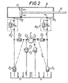
- Figure 2 is similar to Figure 1 but showing the control system with a pump operating in one direction so as to move the piston of the piston and cylinder unit.
- . In the drawings a piston P having a draws fluid from the reservoir G through one-way check valve F2 which now opens and pressure fluid is then pumped at the output C of the pump. The outlet pressure of the fluid from the pump C closes check valve F1 to the reservoir G and when the pressure reaches approximately one half the crack pressure of the check valve D1, the pressure also communicated to valve E1 closes the valve E1 so isolating the corresponding end of cylinder B from the reservoir G. The valve D1 opens at its rated pressure and the pressure then builds up in the corresponding right hand end of cylinder B. At this time fluid in the left hand end of cylinder B is able to travel freely from the cylinder via port B2 to the reservoir G through the open check valve-E2 so that the piston P will move to the left and retract the piston rod R.
- The system works in a similar manner to extend the piston rod R from the cylinder the speed of operation of the system, and the line is additionally connected to the reservoir G through a normally open pilot operated check valve E1.
- The hydraulic line between the pressure check valve D1 and pump output C1 is connected firstly, with the reservoir G through a one-way check valve F1; and secondly, with the check valve B1 on that side of the check valve remote from the reservoir.
- The hydraulic control system of the invention is completed by similar hydraulic connections and valves between the port B2 at the other end of the cylinder B and the other outlet C2 of the pump, the various valves being given the corresponding reference letters with the suscript 2.
- The hydraulic system as shown in Figure '1 is in an inoperative position. In Figure 2 the pump has been manually operated to energize the pump C so that it rotates clockwise in the direction of the arrow. The pump C when the pump C is operated in the opposite anti-clockwise direction.
- Speed control of the system may be obtained by adjustment of the flow control valves A1 and A 2.
- In practice the parts of the system indicated by the reference letter G indicates openings to the hydraulic reservoir and the parts of the system shown by the reference letters C to G are all contained within the reservoir in addition to the hydraulic fluid. The shaft of the pump C protrudes through the front of the reservoir, as do the ports and the reservoir breather/filter. The flow control valves A when required would be mounted to the ports.
- If an outside force is applied to the piston rod R of the cylinder B thus generating a back pressure, the check valves D1, D2 prevent the fluid from reaching the pump C and thereby driving it as a motor. Manual operation of the pump C in this situation could produce enough pressure in the pilot valve line to keep the pilot operated normally open check valves E11 E2 in a closed position thus causing a hydraulic lock. The control system of the invention avoids this problem due to the fact that upon cessation of manual operation of the pump handle, the pressure drop due to leakage across the pump is sufficiently high to cause an instantaneous opening of the pilot operated check valves E1' E2 so that a hydraulic lock is avoided.
- If desired, the one-way check valves D1 and D2 may be each combined as a single, unitary valve structure with its corresponding check valve E1 and E2. In such an arrangement the single valve structure may comprise a ported valve having a valve member which is slidably movable in response to the pump pressure firstly to isolate the reservoir drain line and secondly to open the line between the pump and the corresponding end of the cylinder.
- Furthermore, the actuator may be of the rotary vane type, the movable piston member in such an arrangement comprising a vane angularly movable in a quadrant-shaped cylinder through an arc of approximately 90°
Claims (9)
1. A fluid system for controlling the operation of an actuator consisting of a cylinder (B) containing a piston (P) movable therein, the opposite ends of said cylinder being connected each with an opposite output of a bi-directional pump (C) through a one-way pressure check valve (D1, D2) preventing return flow of fluid from said one cylinder end to said pump (C), said system being further characterised in that each end of said cylinder is furthermore connected to a fluid reservoir (G) through a check valve (E1, E2) which is normally open to permit flow of fluid from said cylinder end to said reservoir (G) but which is adapted to close in response to a predetermined increase in pressure between the-corresponding pump output (C1, C2) and its one-way pressure check valve (D,, D 2).
2. A fluid system as claimed in Claim 1, characterised by a first fluid conduit connecting a first end of said cylinder with said fluid reservoir (G), a first check valve (E1) in said first fluid conduit and normally open for fluid flow from said first cylinder end (B1) to said reservoir (G), a second fluid conduit connecting a first pump output (C1) with said first fluid conduit, a first one-way pressure check valve (D1) in said second fluid conduit for preventing return flow of fluid from said first cylinder end (B1) to said pump, and a third fluid conduit connecting said first pump output (C1) with said first check valve (E1) for closing said check valve in response to a predetermined increase in pressure in said second fluid conduit between said first pump output (C1) and said first one-way pressure check valve ( D1 ) .
3. A fluid system as claimed in Claim 2, characterised by a fourth fluid conduit connecting a second end (B2) of said cylinder with said fluid reservoir (G), a second check valve (E2) in said fourth fluid conduit and normally open for fluid flow from said second .ylinder end (B2) to said reservoir (G), a fifth fluid conduit connecting a second opposite pump output (C2) with said fourth fluid conduit, a second one-way pressure check valve (D2) in said fifth fluid conduit for preventing return flow of fluid from said second cylinder end (B2) to said pump (C), and a sixth fluid conduit connecting said second pump output (C2) with said second check valve (E2) for closing said check valve in response to a predetermined increase in pressure in said fifth fluid conduit between said second pump output (C2) and said second one-way pressure check valve. (E2.).
.4. A fluid system as claimed in Claim 3, characterised by a seventh fluid conduit connecting said second pump output (C2) with said reservoir (G), and by a third check valve (F2) in said seventh fluid conduit for permitting said pump (C) to draw fluid through said third check valve.(F2) when said pump (C) is operating to supply fluid to said one cylinder end (B1).
5. A fluid system as claimed in Claim 4, characterised by an eighth fluid conduit connecting said first pump output (C1) with said reservoir (G), and by a fourth check valve (F1) in said eighth fluid conduit for permitting said pump (C) to draw fluid through said fourth check valve (F1) when said pump (C) is operating to supply fluid to said second cylinder end (B2).
6. A fluid system as claimed in any one of Claims 2 to 5, characterised by a flow control valve (A1, A2) in said first and said fourth fluid conduits, said flow control valves being adjustable to vary the fluid flow so as to control the speed of operation of the system.
7. A fluid system as claimed in any one of the preceding claims, characterised in that the pump is manually operable.
8. A fluid system as claimed in any one of the preceding claims, wherein each one-way pressure check valve and its corresponding check valve is replaced by a single unitary valve structure.
9. An actuator having a fluid control system as claimed in any one of the preceding claims, characterised in that said piston is connected to a piston rod which extends from said cylinder for actuating a device such as a valve.
Applications Claiming Priority (2)
| Application Number | Priority Date | Filing Date | Title |
|---|---|---|---|
| GB8001193 | 1980-01-14 | ||
| GB8001193 | 1980-01-14 |
Publications (1)
| Publication Number | Publication Date |
|---|---|
| EP0032300A1 true EP0032300A1 (en) | 1981-07-22 |
Family
ID=10510622
Family Applications (1)
| Application Number | Title | Priority Date | Filing Date |
|---|---|---|---|
| EP80304547A Withdrawn EP0032300A1 (en) | 1980-01-14 | 1980-12-17 | Fluid control system |
Country Status (4)
| Country | Link |
|---|---|
| EP (1) | EP0032300A1 (en) |
| JP (1) | JPS56101405A (en) |
| AU (1) | AU6596181A (en) |
| ZA (1) | ZA808017B (en) |
Cited By (12)
| Publication number | Priority date | Publication date | Assignee | Title |
|---|---|---|---|---|
| EP0291654A1 (en) * | 1987-05-21 | 1988-11-23 | Ribaudo Vertical Systems Co. | Hydraulic door opening or closing device |
| US5107677A (en) * | 1987-05-21 | 1992-04-28 | Vertran Manufacturing Company | Hydraulic door actuator |
| US5161957A (en) * | 1987-05-21 | 1992-11-10 | Vertran Manufacturing Company | Hydraulic door actuator |
| FR2687206A1 (en) * | 1992-02-12 | 1993-08-13 | Berruyer Jean Jacques | Control device for valves |
| WO1996012108A1 (en) * | 1994-10-13 | 1996-04-25 | Applied Power Inc. | Hydraulic operating device and gearbox provided with such an operating device |
| EP0893605A1 (en) * | 1997-07-23 | 1999-01-27 | HOERBIGER GmbH | Hydraulic drive system |
| GB2422862A (en) * | 2005-02-03 | 2006-08-09 | Schlumberger Holdings | Apparatus for actuating downhole tools |
| WO2008037307A1 (en) * | 2006-09-25 | 2008-04-03 | Robert Bosch Gmbh | Hydrostatic gear mechanism |
| CN105545839A (en) * | 2016-01-29 | 2016-05-04 | 贵阳海之力液压有限公司 | Oil cylinder reversing and volume speed adjusting hydraulic system |
| US9500206B2 (en) | 2013-11-18 | 2016-11-22 | Warner Electric Technology Llc | Fluid pump for a linear actuator |
| EP2346467B1 (en) * | 2008-09-24 | 2019-07-17 | Ekso Bionics, Inc. | Hip and knee actuation systems for lower limb orthotic devices |
| US10724553B2 (en) | 2018-12-06 | 2020-07-28 | Warner Electric Technology Llc | Three position metering valve for a self-contained electro-hydraulic actuator |
Families Citing this family (2)
| Publication number | Priority date | Publication date | Assignee | Title |
|---|---|---|---|---|
| JPS60101301A (en) * | 1983-11-07 | 1985-06-05 | Mitsubishi Heavy Ind Ltd | Regenerating device for brake energy of cylinder |
| JP6247573B2 (en) * | 2014-03-19 | 2017-12-13 | 株式会社ショーワ | Hydraulic actuator |
Citations (1)
| Publication number | Priority date | Publication date | Assignee | Title |
|---|---|---|---|---|
| US3877347A (en) * | 1973-03-13 | 1975-04-15 | Res Engineering Company | Hydraulic control |
-
1980
- 1980-12-17 EP EP80304547A patent/EP0032300A1/en not_active Withdrawn
- 1980-12-22 ZA ZA00808017A patent/ZA808017B/en unknown
-
1981
- 1981-01-05 AU AU65961/81A patent/AU6596181A/en not_active Abandoned
- 1981-01-09 JP JP256181A patent/JPS56101405A/en active Pending
Patent Citations (1)
| Publication number | Priority date | Publication date | Assignee | Title |
|---|---|---|---|---|
| US3877347A (en) * | 1973-03-13 | 1975-04-15 | Res Engineering Company | Hydraulic control |
Cited By (15)
| Publication number | Priority date | Publication date | Assignee | Title |
|---|---|---|---|---|
| EP0291654A1 (en) * | 1987-05-21 | 1988-11-23 | Ribaudo Vertical Systems Co. | Hydraulic door opening or closing device |
| US5107677A (en) * | 1987-05-21 | 1992-04-28 | Vertran Manufacturing Company | Hydraulic door actuator |
| US5161957A (en) * | 1987-05-21 | 1992-11-10 | Vertran Manufacturing Company | Hydraulic door actuator |
| FR2687206A1 (en) * | 1992-02-12 | 1993-08-13 | Berruyer Jean Jacques | Control device for valves |
| US5857381A (en) * | 1994-10-13 | 1999-01-12 | Applied Power Inc. | Hydraulic operating device and gearbox provided with such an operating device |
| NL9401692A (en) * | 1994-10-13 | 1996-05-01 | Applied Power Inc | Hydraulic operating device and gearbox provided with such an operating device. |
| WO1996012108A1 (en) * | 1994-10-13 | 1996-04-25 | Applied Power Inc. | Hydraulic operating device and gearbox provided with such an operating device |
| EP0893605A1 (en) * | 1997-07-23 | 1999-01-27 | HOERBIGER GmbH | Hydraulic drive system |
| GB2422862A (en) * | 2005-02-03 | 2006-08-09 | Schlumberger Holdings | Apparatus for actuating downhole tools |
| WO2008037307A1 (en) * | 2006-09-25 | 2008-04-03 | Robert Bosch Gmbh | Hydrostatic gear mechanism |
| EP2346467B1 (en) * | 2008-09-24 | 2019-07-17 | Ekso Bionics, Inc. | Hip and knee actuation systems for lower limb orthotic devices |
| US9500206B2 (en) | 2013-11-18 | 2016-11-22 | Warner Electric Technology Llc | Fluid pump for a linear actuator |
| US10288064B2 (en) | 2013-11-18 | 2019-05-14 | Warner Electric Technology Llc | Fluid pump for a linear actuator |
| CN105545839A (en) * | 2016-01-29 | 2016-05-04 | 贵阳海之力液压有限公司 | Oil cylinder reversing and volume speed adjusting hydraulic system |
| US10724553B2 (en) | 2018-12-06 | 2020-07-28 | Warner Electric Technology Llc | Three position metering valve for a self-contained electro-hydraulic actuator |
Also Published As
| Publication number | Publication date |
|---|---|
| ZA808017B (en) | 1982-02-24 |
| JPS56101405A (en) | 1981-08-14 |
| AU6596181A (en) | 1981-07-23 |
Similar Documents
| Publication | Publication Date | Title |
|---|---|---|
| EP0032300A1 (en) | Fluid control system | |
| DE2703349C3 (en) | Valve device for controlling a reciprocating piston for upward travel in an elevator car | |
| US3584537A (en) | Hydrostatic steering system | |
| DE2208842C2 (en) | Drive of a steering device and several accessories for vehicles by a hydrostatic transmission | |
| DE2557147C3 (en) | Hydraulic fluid driven rock drilling machine | |
| DE2537960C3 (en) | Valve combination with two valves | |
| GB2140872A (en) | Rotary positive-displacement fluid-machine | |
| DE4000801C1 (en) | ||
| DE3018792A1 (en) | HYDROSTATIC CONTROL DEVICE, IN PARTICULAR STEERING DEVICE | |
| DE2112813A1 (en) | Electro-hydraulic control device | |
| US1993195A (en) | Valve mechanism | |
| DE3507011A1 (en) | Liquid-conveying apparatus, preferably for colorants and chemicals | |
| DE4235698C2 (en) | Hydrostatic drive system | |
| DE4402093B4 (en) | Hydrostatic drive system | |
| DE4443869A1 (en) | Hydraulic auxiliary force braking system for motor vehicle | |
| DE3729898C2 (en) | ||
| DE3003741A1 (en) | DOOR OPERATING ARRANGEMENT | |
| DE3603327A1 (en) | PULSE TOOL WITH SHUT-OFF DEVICE | |
| WO1999009320A1 (en) | Turning control device with brake and control valves | |
| DE2240012B2 (en) | Control device for hydrostatic steering and the like | |
| DE2242920B2 (en) | CONTROL DEVICE FOR THE FEED DRIVE OF A ROCK DRILLING MACHINE | |
| DE2163456A1 (en) | Electro-hydraulic stepper motor | |
| US20030029507A1 (en) | Fluid discharge floodgate improved for cistern aircrafts dedicated to fight fires | |
| DE2655965C3 (en) | Hydraulic delivery rate adjustment system for the adjustment pump of a hydrostatic transmission | |
| DE301944C (en) |
Legal Events
| Date | Code | Title | Description |
|---|---|---|---|
| PUAI | Public reference made under article 153(3) epc to a published international application that has entered the european phase |
Free format text: ORIGINAL CODE: 0009012 |
|
| AK | Designated contracting states |
Designated state(s): AT BE CH DE FR GB IT LU NL SE |
|
| STAA | Information on the status of an ep patent application or granted ep patent |
Free format text: STATUS: THE APPLICATION IS DEEMED TO BE WITHDRAWN |
|
| 18D | Application deemed to be withdrawn |
Effective date: 19820627 |
|
| RIN1 | Information on inventor provided before grant (corrected) |
Inventor name: FRY, JEREMY JOSEPH Inventor name: WARNETT, CHRISTOPHER |