DE202024103958U1 - Cable plow - Google Patents
Cable plow Download PDFInfo
- Publication number
- DE202024103958U1 DE202024103958U1 DE202024103958.0U DE202024103958U DE202024103958U1 DE 202024103958 U1 DE202024103958 U1 DE 202024103958U1 DE 202024103958 U DE202024103958 U DE 202024103958U DE 202024103958 U1 DE202024103958 U1 DE 202024103958U1
- Authority
- DE
- Germany
- Prior art keywords
- fixing device
- carriage
- cable
- sliding bar
- longitudinal cylinder
- Prior art date
- Legal status (The legal status is an assumption and is not a legal conclusion. Google has not performed a legal analysis and makes no representation as to the accuracy of the status listed.)
- Active
Links
- 238000006073 displacement reaction Methods 0.000 claims description 4
- 230000000284 resting effect Effects 0.000 claims description 3
- 238000000034 method Methods 0.000 description 15
- 238000011161 development Methods 0.000 description 2
- 230000018109 developmental process Effects 0.000 description 2
- 239000002689 soil Substances 0.000 description 2
- 238000010276 construction Methods 0.000 description 1
- 230000001419 dependent effect Effects 0.000 description 1
- 230000000694 effects Effects 0.000 description 1
- 239000011435 rock Substances 0.000 description 1
Images


Classifications
-
- E—FIXED CONSTRUCTIONS
- E02—HYDRAULIC ENGINEERING; FOUNDATIONS; SOIL SHIFTING
- E02F—DREDGING; SOIL-SHIFTING
- E02F5/00—Dredgers or soil-shifting machines for special purposes
- E02F5/02—Dredgers or soil-shifting machines for special purposes for digging trenches or ditches
- E02F5/10—Dredgers or soil-shifting machines for special purposes for digging trenches or ditches with arrangements for reinforcing trenches or ditches; with arrangements for making or assembling conduits or for laying conduits or cables
- E02F5/102—Dredgers or soil-shifting machines for special purposes for digging trenches or ditches with arrangements for reinforcing trenches or ditches; with arrangements for making or assembling conduits or for laying conduits or cables operatively associated with mole-ploughs, coulters
-
- E—FIXED CONSTRUCTIONS
- E02—HYDRAULIC ENGINEERING; FOUNDATIONS; SOIL SHIFTING
- E02F—DREDGING; SOIL-SHIFTING
- E02F5/00—Dredgers or soil-shifting machines for special purposes
- E02F5/02—Dredgers or soil-shifting machines for special purposes for digging trenches or ditches
- E02F5/14—Component parts for trench excavators, e.g. indicating devices travelling gear chassis, supports, skids
- E02F5/145—Component parts for trench excavators, e.g. indicating devices travelling gear chassis, supports, skids control and indicating devices
-
- H—ELECTRICITY
- H02—GENERATION; CONVERSION OR DISTRIBUTION OF ELECTRIC POWER
- H02G—INSTALLATION OF ELECTRIC CABLES OR LINES, OR OF COMBINED OPTICAL AND ELECTRIC CABLES OR LINES
- H02G1/00—Methods or apparatus specially adapted for installing, maintaining, repairing or dismantling electric cables or lines
- H02G1/06—Methods or apparatus specially adapted for installing, maintaining, repairing or dismantling electric cables or lines for laying cables, e.g. laying apparatus on vehicle
Landscapes
- Engineering & Computer Science (AREA)
- Mining & Mineral Resources (AREA)
- Mechanical Engineering (AREA)
- Civil Engineering (AREA)
- General Engineering & Computer Science (AREA)
- Structural Engineering (AREA)
- Soil Working Implements (AREA)
Abstract
Kabelpflug (10) zum Einbringen mindestens einer Leitung (11), insbesondere mindestens eines Rohres oder Kabels, in den Untergrund, umfassend ein Fahrgestell (12) mit einem zentralen Körper (13) sowie mit Vorderrädern (14) und Hinterrädern (15),
ein zum Eingriff in den Untergrund geeignetes Schwert (16) zur Bildung einer Erdrinne, wobei das Schwert (16) in einer vorgesehenen Fahrtrichtung (F) hinter dem zentralen Körper (13) an einer Schwerthalterung (17) angeordnet ist,
einen Schiebebalken (18), wobei ein in der vorgesehenen Fahrtrichtung (F) hinten gelegenes Ende des Schiebebalkens (18) an dem zentralen Körper (13) angeordnet ist,
einen Schlitten (19), wobei der Schlitten (19) an dem Schiebebalken (18) verschiebbar angeordnet ist,
eine Fixiervorrichtung (20) als Haltemittel für den Schlitten (19) am Schiebebalken (18),
wobei die Hinterräder (15) am zentralen Körper (13) oder an der Schwerthalterung (17) und die Vorderräder (14) an dem Schlitten (19) angeordnet sind, und
wobei der Abstand (A) zwischen dem zentralen Körper (13) und dem Schlitten (19) und damit der Abstand zwischen den Vorderrädern (14) und den Hinterrädern (15) mittels Verschieben des Schlittens (19) an dem Schiebebalken (18) unter Einsatz der Fixiervorrichtung (20) veränderbar ist.

a blade (16) suitable for engaging in the subsoil to form an earth channel, the blade (16) being arranged on a blade holder (17) behind the central body (13) in an intended direction of travel (F),
a sliding bar (18), wherein an end of the sliding bar (18) located at the rear in the intended direction of travel (F) is arranged on the central body (13),
a carriage (19), wherein the carriage (19) is arranged displaceably on the sliding bar (18),
a fixing device (20) as a holding means for the carriage (19) on the sliding bar (18),
wherein the rear wheels (15) are arranged on the central body (13) or on the sword holder (17) and the front wheels (14) on the carriage (19), and
wherein the distance (A) between the central body (13) and the carriage (19) and thus the distance between the front wheels (14) and the rear wheels (15) can be changed by moving the carriage (19) on the sliding bar (18) using the fixing device (20).
Description
Die Erfindung betrifft einen Kabelpflug zum Einbringen mindestens einer Leitung, insbesondere mindestens eines Rohres oder Kabels, in den Untergrund.The invention relates to a cable plough for introducing at least one line, in particular at least one pipe or cable, into the ground.
Bei Kabelpflügen dieser Bauart wird das gesamte Gerät von einem Seil gezogen, das von einem entfernt stehenden Zugfahrzeug über eine Winde seine Zugkraft erhält. Dieses Seil greift in der Nähe der in Fahrtrichtung vorn gelegenen Schneidkante des Schwertes an einem Rahmenteil des Kabelpflugs an. Wird das Schwert relativ tief in den Erdboden eingelassen, dann wird in Fahrtrichtung betrachtet der Abstand zwischen der unten gelegenen Schwertspitze und einer gedanklich durch die Vorderräder gelegten senkrechten Ebene immer kürzer, da die Schwertspitze, in Fahrtrichtung betrachtet, weiter vorn liegt als der obere, am Gerät angebrachte Bereich des Schwertes. Beim Pflugbetrieb wird das Schwert seiner Funktion gemäß gegen den Widerstand des Erdreiches durch dieses hindurch gedrückt. Damit entsteht aufgrund der Zugkraft des Seiles, das aufgrund seines Angriffspunktes am oder nahe dem oberen Bereich des Schwertes auf den oberhalb des Erdbodens befindlichen Geräterahmen in Fahrtrichtung wirkt, ein Drehmoment um die Schwertspitze. Dabei ist die Drehrichtung des Drehmomentes so, dass es das Gerät um die Schwertspitze nach vorn schwenken will. Dies hat ein mehr oder weniger tiefes Eindrücken der Vorderräder in den Erdboden zur Folge. Dabei können die Vorderräder, insbesondere bei weichem Boden, so tief in ihn eingedrückt werden, dass hierdurch die Weiterfahrt des Kabelpfluges blockiert wird. Der gleiche nachteilige Effekt kann auch dann eintreten, wenn während des Pflugvorganges das Schwert an ein Hindernis, beispielsweise einen Fels oder eine starke Baumwurzel, stößt, das es nur mit erheblichem zusätzlichen Kraftaufwand des Seilzuges zerteilen oder zur Seite drücken kann. Dies gilt im Übrigen auch dann, wenn ein solches Gerät durch einen eigenen, auf die Hinterräder wirkenden Antrieb vorwärts bewegt wird. Auch in den vorgenannten Fällen tritt ein entsprechend starkes Drehmoment um die Schwertkante oder Schwertspitze auf, woraus sich das vorstehend bereits erläuterte Eindrücken der Vorderräder in den Erdboden ergibt. Hierdurch wird der Arbeitsvorgang empfindlich gestört. Dies hat Zeitverluste und unter Umständen auch Schäden am Kabelpflug selbst sowie Flurschäden zur Folge.In cable ploughs of this type, the entire machine is pulled by a cable that receives its pulling power from a distant towing vehicle via a winch. This cable attaches to a part of the frame of the cable plough near the cutting edge of the blade, which is at the front in the direction of travel. If the blade is sunk relatively deep into the ground, then the distance between the lower blade tip and a vertical plane that is imaginarily drawn through the front wheels becomes increasingly shorter when viewed in the direction of travel, since the blade tip, when viewed in the direction of travel, is further forward than the upper part of the blade attached to the machine. When ploughing, the blade is pushed through the soil against the resistance of the soil in accordance with its function. This creates a torque around the blade tip due to the pulling force of the cable, which acts on the device frame above the ground in the direction of travel due to its point of attack at or near the upper part of the blade. The direction of rotation of the torque is such that it wants to swing the device forwards around the blade tip. This results in the front wheels being pressed more or less deeply into the ground. The front wheels can be pressed so deeply into the ground, particularly on soft ground, that the cable plow cannot continue to move. The same disadvantageous effect can also occur if the blade hits an obstacle during the plowing process, such as a rock or a strong tree root, which it can only cut or push to the side with considerable additional force from the cable. This also applies if such a device is moved forwards by its own drive acting on the rear wheels. In the aforementioned cases, a correspondingly strong torque occurs around the blade edge or blade tip, resulting in the pressing of the front wheels into the ground as already explained above. This seriously disrupts the work process. This results in time being lost and, in some cases, damage to the cable plow itself and damage to the land.
Es ist daher Aufgabe der Erfindung, einen neuen Kabelpflug anzugeben, insbesondere einen Kabelpflug bei dem der Abstand der Vorderräder und der Hinterräder variabel ist.It is therefore an object of the invention to provide a new cable plough, in particular a cable plough in which the distance between the front wheels and the rear wheels is variable.
Diese Aufgabe wird gelöst durch die Merkmale des Anspruchs 1. Vorteilhafte Ausgestaltungen und Weiterbildungen sind in den abhängigen Ansprüchen angegeben.This object is achieved by the features of claim 1. Advantageous embodiments and further developments are specified in the dependent claims.
Der erfindungsgemäße Kabelpflug umfasst ein Fahrgestell mit einem zentralen Körper sowie mit Vorderrädern und Hinterrädern. Ferner umfasst der Kabelpflug ein zum Eingriff in den Untergrund geeignetes Schwert zur Bildung einer Erdrinne, wobei das Schwert in einer vorgesehenen Fahrtrichtung hinter dem zentralen Körper an einer Schwerthalterung angeordnet ist. Der Kabelpflug umfasst ferner einen Schiebebalken, wobei ein in der vorgesehenen Fahrtrichtung hinten gelegenes Ende des Schiebebalkens an dem zentralen Körper angeordnet ist. Des Weiteren umfasst der Kabelpflug einen Schlitten, wobei der Schlitten an dem Schiebebalken verschiebbar angeordnet ist. Der Kabelpflug umfasst auch eine Fixiervorrichtung als Haltemittel für den Schlitten am Schiebebalken. Die Hinterräder sind am zentralen Körper oder an der Schwerthalterung und die Vorderräder an dem Schlitten angeordnet. Der Abstand zwischen dem zentralen Körper und dem Schlitten und damit der Abstand zwischen den Vorderrädern und den Hinterrädern ist mittels Verschieben des Schlittens an dem Schiebebalken unter Einsatz der Fixiervorrichtung veränderbar.The cable plow according to the invention comprises a chassis with a central body and with front wheels and rear wheels. The cable plow also comprises a blade suitable for engaging in the ground to form an earth channel, wherein the blade is arranged on a blade holder behind the central body in a designated direction of travel. The cable plow also comprises a sliding beam, wherein an end of the sliding beam located at the rear in the designated direction of travel is arranged on the central body. The cable plow also comprises a carriage, wherein the carriage is arranged displaceably on the sliding beam. The cable plow also comprises a fixing device as a holding means for the carriage on the sliding beam. The rear wheels are arranged on the central body or on the blade holder and the front wheels on the carriage. The distance between the central body and the carriage and thus the distance between the front wheels and the rear wheels can be changed by moving the carriage on the sliding beam using the fixing device.
Die Vorteile der Erfindung liegen insbesondere darin, dass durch eine Vergrößerung des Abstandes der Vorderräder von den Hinterrädern und damit auch vom Schwert bei einem Fahr- und Pflugbetrieb im entsprechenden Gelände und entsprechender Gefahr des Auftretens eines schädlichen Drehmomentes durch diese Vergrößerung die auf die Vorderräder in Richtung zum Erdboden hinwirkende Druckkraft entsprechend verringert werden. Je größer der vorgenannte Abstand ist, desto kleiner wird bei gleichem Drehmoment die vorgenannte Druckkraft. Andererseits gibt es aber beim Betrieb eines solchen Kabelpfluges in der Praxis auch Situationen, in denen der vorgenannte Abstand, und damit auch der Achsabstand zwischen Vorderrädern und Hinterrädern, möglichst klein sein soll. Dies ist zum Beispiel dann der Fall, wenn auf Straßen oder Wegen zu fahren ist, die relativ schmal sind und an den Biegungen einen kleinen Kurvenradius haben. In solchen Fällen würde ein zu großer Achsabstand entweder das Durchfahren solcher Kurven überhaupt unmöglich machen oder zumindest ein mehrfaches Vor- und Rücksetzen des gesamten Gerätes erfordern. Dies ist nicht nur umständlich, sondern kann bei weichem Boden auch zu Beschädigungen des Bodens oder zu einem Eingraben der Räder in den Boden führen. Auch ist ein geringer Achsabstand dann erforderlich, wenn ein solcher Kabelpflug auf einem Tieflader untergebracht und durch diesen an eine andere Baustelle transportiert werden soll, da andernfalls, das heißt bei einem zu großen Achsabstand, der Kabelpflug nicht mehr auf den Tieflader passen würde. Mit der Erfindung kann nun der Achsabstand, je nach den Erfordernissen der entsprechenden Situation, vergrößert oder aber verkleinert werden.The advantages of the invention are in particular that by increasing the distance between the front wheels and the rear wheels and thus also from the blade when driving and plowing in the corresponding terrain and with the corresponding risk of a damaging torque occurring due to this increase, the pressure force acting on the front wheels towards the ground is reduced accordingly. The larger the aforementioned distance, the smaller the aforementioned pressure force becomes for the same torque. On the other hand, when operating such a cable plow, there are also situations in practice in which the aforementioned distance, and thus also the axle distance between the front wheels and rear wheels, should be as small as possible. This is the case, for example, when driving on roads or paths that are relatively narrow and have a small curve radius at the bends. In such cases, an axle distance that is too large would either make it impossible to drive through such curves at all or at least require the entire device to be moved forwards and backwards several times. This is not only inconvenient, but on soft ground it can also damage the ground or cause the wheels to dig into the ground. A small axle distance is also necessary if such a cable plough is to be placed on a low-loader and transported to another construction site, because otherwise, i.e. if the axle distance is too large, the cable plough would no longer fit on the low-loader. According to the invention, the center distance can now be increased or reduced depending on the requirements of the situation.
Die Fixiervorrichtung ist bevorzugt, insbesondere über einen Längszylinder, am Schlitten angeordnet ist, wobei die Fixiervorrichtung insbesondere an einem in der vorgesehenen Fahrtrichtung vorderen Ende des Schlittens angeordnet ist.The fixing device is preferably arranged on the carriage, in particular via a longitudinal cylinder, wherein the fixing device is arranged in particular at a front end of the carriage in the intended direction of travel.
Die Fixiervorrichtung weist bevorzugt zwei Klammerbacken zum Umgreifen des Schiebebalkens auf, wobei jede Klammerbacke eine Anlagefläche zum Anliegen am Schiebebalken aufweist, wobei die Anlageflächen an zwei ersten, insbesondere unteren, Enden der Klammerbacken vorgesehen sind. Die Anlagenflächen der Klammerbacken sind sich insbesondere zugewandt.The fixing device preferably has two clamp jaws for gripping the sliding bar, each clamp jaw having a contact surface for resting on the sliding bar, the contact surfaces being provided at two first, in particular lower, ends of the clamp jaws. The contact surfaces of the clamp jaws in particular face each other.
Der Schiebebalken weist beispielsweise eine „T“- oder „Doppel-T“-förmige Form im Querschnitt zu seiner Längsachse L auf. Es kann vorgesehen sein, dass der obere, breitere Bereich des T"- oder „Doppel-T“-förmigen Schiebebalkens von den Klammerbacken umgriffen wird.The sliding bar has, for example, a "T" or "double-T"-shaped form in cross-section to its longitudinal axis L. It can be provided that the upper, wider area of the "T" or "double-T"-shaped sliding bar is gripped by the clamp jaws.
Die Fixiervorrichtung weist insbesondere ein U-förmiges Grundprofil auf, wobei das Grundprofil bevorzugt auf den Schiebebalken aufsetzbar ist. Das Grundprofil weist einen Querschenkel und zwei Längsschenkel auf. Die Klammerbacken sind vorzugsweise an den Außenflächen der Längsschenkel angeordnet.The fixing device has in particular a U-shaped base profile, wherein the base profile can preferably be placed on the sliding bar. The base profile has a transverse leg and two longitudinal legs. The clamp jaws are preferably arranged on the outer surfaces of the longitudinal legs.
Gemäß einer Weiterbildung weist die Fixiervorrichtung einen senkrecht zur Längsachse des Schiebebalkens angeordneten Querzylinder auf, wobei der Querzylinder zwischen zwei den ersten Enden der Klammerbacken gegenüberliegenden zweiten Enden der Klammerbacken angeordnet ist.According to a further development, the fixing device has a transverse cylinder arranged perpendicular to the longitudinal axis of the sliding bar, wherein the transverse cylinder is arranged between two second ends of the clamp jaws opposite the first ends of the clamp jaws.
Der Querzylinder kann ein Hydraulikzylinder sein. Alternativ kann es sich bei dem Querzylinder auch um einen Pneumatikzylinder handeln. Der Querzylinder ist vorzugsweise an der Oberseite des Querschenkels angeordnet.The cross cylinder can be a hydraulic cylinder. Alternatively, the cross cylinder can also be a pneumatic cylinder. The cross cylinder is preferably arranged on the top of the cross leg.
Gemäß einer bevorzugten Ausführungsvariante der Erfindung ist vorgesehen, dass die Klammerbacken an ihren zweiten Enden mittels ersten Drehgelenken an den beiden Enden des Querzylinders und in einem Bereich, insbesondere mittig, zwischen den beiden Enden der Klammerbacken mittels zweiten Drehgelenken an Außenflächen der Fixiervorrichtung angeordnet sind, so dass ein Kippmechanismus realisiert wird, bei dem die Anlageflächen der Klammerbacken bei eingefahrenem Querzylinder voneinander weggekippt sind, so dass die Anlageflächen der Klammerbacken beabstandet zum Schiebebalken sind, so dass die Fixiervorrichtung vom Schiebebalken gelöst ist, und bei dem die Anlageflächen der Klammerbacken bei ausgefahrenem Querzylinder derart, insbesondere senkrecht zur Längsachse des Schiebebalkens, angeordnet sind, dass die Anlageflächen der Klammerbacken am Schiebebalken anliegen, so dass die Fixiervorrichtung am Schiebebalken fixiert ist. Bevorzugt ist an den Außenflächen der Längsschenkel jeweils eine Aufnahme für die zweiten Drehgelenke angeordnet.According to a preferred embodiment of the invention, the clamp jaws are arranged at their second ends by means of first swivel joints at the two ends of the transverse cylinder and in an area, in particular centrally, between the two ends of the clamp jaws by means of second swivel joints on outer surfaces of the fixing device, so that a tilting mechanism is realized in which the contact surfaces of the clamp jaws are tilted away from each other when the transverse cylinder is retracted, so that the contact surfaces of the clamp jaws are spaced from the sliding bar, so that the fixing device is released from the sliding bar, and in which the contact surfaces of the clamp jaws are arranged when the transverse cylinder is extended, in particular perpendicular to the longitudinal axis of the sliding bar, such that the contact surfaces of the clamp jaws rest on the sliding bar, so that the fixing device is fixed to the sliding bar. Preferably, a receptacle for the second swivel joints is arranged on the outer surfaces of the longitudinal legs.
Zwischen Fixiervorrichtung und Schlitten ist besonders bevorzugt ein Längszylinder angeordnet, wobei der Längszylinder parallel zur Längsachse des Schiebebalkens ausgerichtet ist, wobei der Abstand zwischen Fixiervorrichtung und Schlitten mittels des Längszylinders veränderbar ist, wobei der Längszylinder einen eingefahrenen Zustand, in dem die Fixiervorrichtung am Schlitten oder im Bereich des Schlittens angeordnet ist, und einen ausgefahrenen Zustand aufweist, in dem die Fixiervorrichtung vom Schlitten beabstandet ist. Der Längszylinder kann ein Hydraulikzylinder sein. Alternativ kann es sich bei dem Längszylinder auch um einen Pneumatikzylinder handeln. Die Ausfahrlänge des Längszylinders ist vorzugsweise kürzer als die Länge des Schiebebalkens.A longitudinal cylinder is particularly preferably arranged between the fixing device and the slide, the longitudinal cylinder being aligned parallel to the longitudinal axis of the sliding bar, the distance between the fixing device and the slide being variable by means of the longitudinal cylinder, the longitudinal cylinder having a retracted state in which the fixing device is arranged on the slide or in the area of the slide, and an extended state in which the fixing device is spaced apart from the slide. The longitudinal cylinder can be a hydraulic cylinder. Alternatively, the longitudinal cylinder can also be a pneumatic cylinder. The extended length of the longitudinal cylinder is preferably shorter than the length of the sliding bar.
Es kann vorgesehen sein, dass der Abstand zwischen dem zentralen Körper und dem Schlitten mittels Verschieben des Schlittens an dem Schiebebalken veränderbar ist, indem der Schlitten mittels der Fixiervorrichtung und des Längszylinders in einer raupenartigen Bewegung entlang des Schiebebalkens verschoben wird oder verschiebbar ist.It can be provided that the distance between the central body and the carriage can be changed by moving the carriage on the sliding beam, in that the carriage is moved or can be moved along the sliding beam in a caterpillar-like movement by means of the fixing device and the longitudinal cylinder.
Bevorzugt bewirkt bei fixierter Fixiervorrichtung ein Einfahren des Längszylinders eine Bewegung des Schlittens hin zur Fixiervorrichtung, und bei gelöster Fixiervorrichtung ein Ausfahren des Längszylinders eine Bewegung der Fixiervorrichtung weg vom Schlitten.Preferably, when the fixing device is fixed, retraction of the longitudinal cylinder causes a movement of the carriage towards the fixing device, and when the fixing device is released, extension of the longitudinal cylinder causes a movement of the fixing device away from the carriage.
Es kann vorgesehen sein, dass die raupenartige Bewegung in der vorgesehenen Fahrtrichtung realisierbar ist, indem die Fixiervorrichtung gelöst wird und der Längszylinder ausgefahren wird, so dass die Fixiervorrichtung vom Schlitten wegbewegt wird, und indem, insbesondere anschließend, die Fixiervorrichtung fixiert wird und der Längszylinders eingefahren wird, so dass der Schlitten zur Fixiervorrichtung hinbewegt wird.It can be provided that the caterpillar-like movement in the intended direction of travel can be realized by releasing the fixing device and extending the longitudinal cylinder so that the fixing device is moved away from the carriage, and by, in particular subsequently, fixing the fixing device and retracting the longitudinal cylinder so that the carriage is moved towards the fixing device.
Bevorzugt wird dieser Vorgang solange wiederholt, bis die gewünschte Position des Schlittens am Schiebebalken und damit der gewünschte Abstand zwischen Vorderrädern und Hinterrädern erreicht ist. Es kann auch vorgesehen sein, dass der Längszylinder nur teilweise eingefahren und ausgefahren wird. Selbstverständlich kann der vorgenannte Vorgang an jedem der beschriebenen Teilschritte beginnen. Dies ist letztlich abhängig davon, in welchem Zustand sich Fixiervorrichtung und/oder Längszylinder zu Beginn des Verschiebevorgangs befinden.Preferably, this process is repeated until the desired position of the carriage on the sliding beam and thus the desired distance between the front wheels and rear wheels is reached. It can also be provided that the longitudinal cylinder is only partially retracted and extended. Of course, the above-mentioned process can be carried out on any of the parts described. steps begin. This ultimately depends on the state of the fixing device and/or longitudinal cylinder at the start of the shifting process.
Es kann vorgesehen sein, dass bei fixierter Fixiervorrichtung ein Ausfahren des Längszylinders eine Bewegung des Schlittens weg von der Fixiervorrichtung bewirkt, und bei gelöster Fixiervorrichtung ein Einfahren des Längszylinders eine Bewegung der Fixiervorrichtung hin zum Schlitten bewirkt.It can be provided that when the fixing device is fixed, extending the longitudinal cylinder causes the carriage to move away from the fixing device, and when the fixing device is released, retracting the longitudinal cylinder causes the fixing device to move towards the carriage.
Ferner kann vorgesehen sein, dass die raupenartige Bewegung entgegengesetzt der vorgesehenen Fahrtrichtung realisierbar ist, indem die Fixiervorrichtung fixiert wird und der Längszylinder ausgefahren wird, so dass der Schlitten von der Fixiervorrichtung wegbewegt wird, und indem, insbesondere anschließend, die Fixiervorrichtung gelöst wird und der Längszylinders eingefahren wird, so dass die Fixiervorrichtung zum Schlitten hinbewegt wird.Furthermore, it can be provided that the caterpillar-like movement can be realized opposite to the intended direction of travel by fixing the fixing device and extending the longitudinal cylinder so that the carriage is moved away from the fixing device and by, in particular subsequently, releasing the fixing device and retracting the longitudinal cylinder so that the fixing device is moved towards the carriage.
Selbstverständlich kann auch der vorgenannte Verschiebevorgang entgegen der vorgesehenen Fahrtrichtung an jedem der beschriebenen Teilschritte beginnen. Dies ist abhängig davon, in welchem Zustand sich Fixiervorrichtung und/oder Längszylinder zu Beginn des Verschiebevorgangs befinden.Of course, the aforementioned shifting process can also begin in the opposite direction to the intended direction of travel at any of the described sub-steps. This depends on the state of the fixing device and/or longitudinal cylinder at the start of the shifting process.
Gemäß einer Ausführungsvariante der Erfindung umfasst der Kabelpflug eine Leitungsführung zum Einlegen der Leitung in die durch das Schwert gebildete oder bildbare Erdrinne, wobei die Leitungsführung in der vorgesehenen Fahrtrichtung vorzugsweise hinter dem Schwert angeordnet ist.According to one embodiment of the invention, the cable plough comprises a cable guide for inserting the cable into the earth channel formed or formable by the blade, wherein the cable guide is preferably arranged behind the blade in the intended direction of travel.
Gemäß einer Ausführungsvariante der Erfindung ist vorgesehen, dass die Hinterräder über Abstützungen verstellbar am zentralen Körper oder der Schwerthalterung angebracht sind, und/oder dass die Vorderräder über Abstützungen verstellbar am Schlitten angebracht sind.According to a variant embodiment of the invention, it is provided that the rear wheels are adjustably mounted on the central body or the sword holder via supports, and/or that the front wheels are adjustably mounted on the carriage via supports.
Am zentralen Körper kann ein Fahrerstand angeordnet sein. Insbesondere weist der Kabelpflug je zwei Vorderräder und Hinterräder auf.A driver's station can be arranged on the central body. In particular, the cable plough has two front wheels and two rear wheels.
Die Erfindung wird nachstehend auch hinsichtlich weiterer Merkmale und Vorteile anhand der Beschreibung von Ausführungsbeispielen und unter Bezugnahme auf die beiliegenden schematischen Zeichnungen näher erläutert. Es zeigen
-
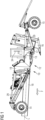
1 ein Ausführungsbeispiel eines erfindungsgemäßen Kabelpflugs mit dem Schlitten in einer ersten Position in einer Seitenansicht, -
2 den Schlitten und die Fixiervorrichtung eines Ausführungsbeispiels eines erfindungsgemäßen Kabelpflugs in einer dreidimensionalen Ansicht; -
3 die Fixiervorrichtung eines Ausführungsbeispiels eines erfindungsgemäßen Kabelpflugs in einer dreidimensionalen Ansicht; -
4 die Fixiervorrichtung nach3 in einer Frontansicht; -
5 ein Ausführungsbeispiel eines erfindungsgemäßen Kabelpflugs mit dem Schlitten in einer zweiten Position in einer Seitenansicht; -
6 eine schematische Ablaufskizze des Verschiebevorgangs des Schlittens an dem Schiebebalken eines erfindungsgemäßen Kabelpflugs.
-
1 an embodiment of a cable plough according to the invention with the carriage in a first position in a side view, -
2 the carriage and the fixing device of an embodiment of a cable plow according to the invention in a three-dimensional view; -
3 the fixing device of an embodiment of a cable plow according to the invention in a three-dimensional view; -
4 the fixing device after3 in a front view; -
5 an embodiment of a cable plough according to the invention with the carriage in a second position in a side view; -
6 a schematic flow chart of the sliding process of the carriage on the sliding beam of a cable plough according to the invention.
Einander entsprechende Teile und Komponenten sind in den Figuren, auch über die verschiedenen Ausführungsbeispiele hinweg, mit den gleichen Bezugszeichen bezeichnet.Corresponding parts and components are designated by the same reference numerals in the figures, even across the various embodiments.
Der Kabelpflug 10 umfasst ferner ein zum Eingriff in den Untergrund geeignetes Schwert 16 zur Bildung einer Erdrinne, wobei das Schwert 16 in einer vorgesehenen Fahrtrichtung F hinter dem zentralen Körper 13 an einer Schwerthalterung 17 angeordnet ist. Auch umfasst der Kabelpflug 10 eine (nicht in
Die Hinterräder 15 sind über Abstützungen 29 am zentralen Körper 13 und die Vorderräder 14 über Abstützungen 29 an dem Schlitten 19 angeordnet, wobei der Abstand A zwischen dem zentralen Körper 13 und dem Schlitten 19 und damit der Abstand zwischen den Vorderrädern 14 und den Hinterrädern 15 mittels Verschieben des Schlittens 19 an dem Schiebebalken 18 unter Einsatz der Fixiervorrichtung 20 veränderbar ist. The
Die Fixiervorrichtung 20 weist ein U-förmiges Grundprofil 30 auf, wobei das Grundprofil 30 auf den Schiebebalken 18 aufsetzbar ist. Das Grundprofil 30 weist einen Querschenkel 31 und zwei Längsschenkel 32 auf. Die Klammerbacken 21 sind an den Außenflächen 26 der Längsschenkel 32 angeordnet.The fixing
Die Fixiervorrichtung 20 weist einen senkrecht zur Längsachse L des Schiebebalkens 18 angeordneten Querzylinder 23 auf, wobei der Querzylinder 23 zwischen zwei den ersten Enden der Klammerbacken 21 gegenüberliegenden zweiten Enden der Klammerbacken 21 angeordnet ist. Der Querzylinder 23 ist bevorzugt ein Hydraulikzylinder. Der Querzylinder 23 ist an der Oberseite des Querschenkels 31 angeordnet.The fixing
Die Klammerbacken 21 sind an ihren zweiten Enden mittels ersten Drehgelenken 24 an den beiden Enden des Querzylinders 23 und in einem Bereich mittig zwischen den beiden Enden der Klammerbacken 21 mittels zweiten Drehgelenken 25 an den Außenflächen 26 der Fixiervorrichtung 20 angeordnet. An den Außenflächen 26 der Längsschenkel 32 ist jeweils eine Aufnahme 33 für die zweiten Drehgelenke 25 angeordnet. Somit wird ein Kippmechanismus realisiert, bei dem die Anlageflächen 22 der Klammerbacken 21 bei eingefahrenem Querzylinder 23 voneinander weggekippt sind, so dass die Anlageflächen 22 der Klammerbacken 21 beabstandet zum Schiebebalken 18 sind, so dass wiederum die Fixiervorrichtung 20 vom Schiebebalken 18 gelöst ist, und bei dem die Anlageflächen 22 der Klammerbacken 21 bei ausgefahrenem Querzylinder 23 derart senkrecht zur Längsachse L des Schiebebalkens 18 angeordnet sind, dass die Anlageflächen 22 der Klammerbacken 21 am Schiebebalken 18 anliegen, so dass die Fixiervorrichtung 20 am Schiebebalken 18 fixiert ist.
Zwischen Fixiervorrichtung 20 und Schlitten 19 ist, wie
Der Abstand A zwischen dem zentralen Körper 13 und dem Schlitten 19 ist mittels Verschieben des Schlittens 19 an dem Schiebebalken 18 veränderbar, indem der Schlitten 19 mittels der Fixiervorrichtung 20 und des Längszylinders 27 in einer raupenartigen Bewegung entlang des Schiebebalkens 18 verschoben wird. Bei fixierter Fixiervorrichtung 20 bewirkt ein Einfahren des Längszylinders 27 eine Bewegung des Schlittens 19 hin zur Fixiervorrichtung 20 und bei geöster Fixiervorrichtung 20 ein Ausfahren des Längszylinders 27 eine Bewegung der Fixiervorrichtung 20 weg vom Schlitten 19. Bei fixierter Fixiervorrichtung 20 bewirkt ein Ausfahren des Längszylinders 27 eine Bewegung des Schlittens 19 weg von der Fixiervorrichtung 20. Bei gelöster Fixiervorrichtung 20 bewirkt ein Einfahren des Längszylinders 27 eine Bewegung der Fixiervorrichtung 20 hin zum Schlitten 19.The distance A between the
Die raupenartige Bewegung ist in der vorgesehenen Fahrtrichtung F realisierbar, indem die Fixiervorrichtung 20 gelöst wird und der Längszylinder 27 anschließend ausgefahren wird, so dass die Fixiervorrichtung 20 in der vorgesehenen Fahrtrichtung F vom Schlitten 19 wegbewegt wird, und indem die Fixiervorrichtung 20 anschließend wieder am Schiebebalken 18 fixiert wird und der Längszylinder 27 daraufhin eingefahren wird, so dass der Schlitten 19 in der vorgesehenen Fahrtrichtung F zur Fixiervorrichtung 20 hinbewegt wird. Dieser Vorgang wird solange wiederholt, bis die gewünschte Position des Schlittens 19 am Schiebebalken 18 und damit der gewünschte Abstand zwischen Vorderrädern 14 und Hinterrädern 15 erreicht ist. Es kann auch vorgesehen sein, dass der Längszylinder 27, insbesondere in einem letzten Schritt, nur teilweise eingefahren wird, um eine exakte Positionierung des Schlittens 19 am Schiebebalken 18 zu ermöglichen. Der vorangehend erläuterte Verschiebevorgang ist schematisch in
Die raupenartige Bewegung ist entgegengesetzt der vorgesehenen Fahrtrichtung F realisierbar, indem die Fixiervorrichtung 20 fixiert wird und der Längszylinder 27 ausgefahren wird, so dass der Schlitten 19 entgegen der vorgesehenen Fahrtrichtung F von der Fixiervorrichtung 20 wegbewegt wird, und indem die Fixiervorrichtung 20 anschließend gelöst wird und der Längszylinder 27 eingefahren wird, so dass die Fixiervorrichtung 20 entgegen der vorgesehenen Fahrtrichtung F zum Schlitten 20 hinbewegt wird. Auch dieser Vorgang wird solange wiederholt, bis die gewünschte Position des Schlittens 19 am Schiebebalken 18 und damit der gewünschte Abstand zwischen Vorderrädern 14 und Hinterrädern 15 erreicht ist. Selbstverständlich kann auch der vorgenannte Verschiebevorgang entgegen der vorgesehenen Fahrtrichtung F an jedem der beschriebenen Teilschritte beginnen. Dies ist ebenfalls abhängig davon, in welchem Zustand sich Fixiervorrichtung 20 und/oder Längszylinder 27 zu Beginn des Verschiebevorgangs befinden.The caterpillar-like movement can be implemented in the opposite direction to the intended direction of travel F by fixing the fixing
BezugszeichenlisteList of reference symbols
- 1010
- KabelpflugCable plow
- 1111
- LeitungLine
- 1212
- Fahrgestellchassis
- 1313
- zentraler Körpercentral body
- 1414
- VorderräderFront wheels
- 1515
- HinterräderRear wheels
- 1616
- Schwertsword
- 1717
- SchwerthalterungSword holder
- 1818
- SchiebebalkenSlide bar
- 1919
- SchlittenSleds
- 2020
- FixiervorrichtungFixing device
- 2121
- KlammerbackeClamp jaw
- 2222
- AnlageflächeContact surface
- 2323
- QuerzylinderCross cylinder
- 2424
- erstes Drehgelenkfirst swivel joint
- 2525
- zweites Drehgelenksecond swivel joint
- 2626
- AußenflächeExterior surface
- 2727
- LängszylinderLongitudinal cylinder
- 2828
- LeitungsführungCable routing
- 2929
- AbstützungSupport
- 3030
- GrundprofilBasic profile
- 3131
- QuerschenkelCross leg
- 3232
- LängsschenkelLongitudinal leg
- 3333
- AufnahmeRecording
- 3434
- Fahrerstand Driver's cab
- FF
- FahrtrichtungDirection of travel
- AA
- AbstandDistance
- LL
- LängsachseLongitudinal axis
Claims (15)
Priority Applications (1)
| Application Number | Priority Date | Filing Date | Title |
|---|---|---|---|
| DE202024103958.0U DE202024103958U1 (en) | 2024-07-15 | 2024-07-15 | Cable plow |
Applications Claiming Priority (1)
| Application Number | Priority Date | Filing Date | Title |
|---|---|---|---|
| DE202024103958.0U DE202024103958U1 (en) | 2024-07-15 | 2024-07-15 | Cable plow |
Publications (1)
| Publication Number | Publication Date |
|---|---|
| DE202024103958U1 true DE202024103958U1 (en) | 2024-08-01 |
Family
ID=92459476
Family Applications (1)
| Application Number | Title | Priority Date | Filing Date |
|---|---|---|---|
| DE202024103958.0U Active DE202024103958U1 (en) | 2024-07-15 | 2024-07-15 | Cable plow |
Country Status (1)
| Country | Link |
|---|---|
| DE (1) | DE202024103958U1 (en) |
Cited By (1)
| Publication number | Priority date | Publication date | Assignee | Title |
|---|---|---|---|---|
| CN121546477A (en) * | 2026-01-21 | 2026-02-17 | 成都仪隆电子有限公司 | Building cable laying device |
-
2024
- 2024-07-15 DE DE202024103958.0U patent/DE202024103958U1/en active Active
Cited By (1)
| Publication number | Priority date | Publication date | Assignee | Title |
|---|---|---|---|---|
| CN121546477A (en) * | 2026-01-21 | 2026-02-17 | 成都仪隆电子有限公司 | Building cable laying device |
Similar Documents
| Publication | Publication Date | Title |
|---|---|---|
| CH650299A5 (en) | SCREW EXCAVATOR. | |
| DE2309014C2 (en) | Leveler | |
| EP3557977B1 (en) | Device for undercutting and removing root balls | |
| DE102016106506B4 (en) | Cable plow | |
| DE8708508U1 (en) | Trail tracker | |
| DE202024103958U1 (en) | Cable plow | |
| DE102016111012B4 (en) | cable plow | |
| EP1167636B1 (en) | Device for forming a trench in the soil | |
| EP1167635A1 (en) | Arrangement for inserting a conduit | |
| DE3642809A1 (en) | MACHINE FOR MILLING OR PEELING ROAD Paving | |
| DE2559523B2 (en) | Planting unit of a planting vehicle | |
| DE3245626C2 (en) | Chassis for a working device for laying cables, flexible pipes or the like. | |
| DE10115456B4 (en) | Laying plow with apron-like displacer device | |
| DE4017379C1 (en) | Cable plough towable for cable laying - allows distance between front wheels and share to be varied and fixed in selected position | |
| DE2734266C3 (en) | Mobile device for laying flexible pipes or cables | |
| DE102013103642B4 (en) | leveling | |
| DE102023105078B4 (en) | Pipe laying device and pipe laying method hereby | |
| EP0623707A2 (en) | Levelling apparatus for attaching to an attachment frame on the front of a selfpropelled vehicle | |
| DE1249707B (en) | Towing hook coupling for tractors | |
| DE202014105813U1 (en) | Leveling and / or clearing vehicle and adjustable clearing device therefor | |
| DE2805536C3 (en) | Device for towing an elongated transport unit | |
| DE202019105045U1 (en) | Installation device and installation for a laying device | |
| DE202019101374U1 (en) | Device for creating a soil profile to promote germination and establishment of seedlings and plants in the forest | |
| DE3740081C2 (en) | ||
| DE102022116336A1 (en) | Agricultural machine, preferably a tractor, with a swivel arm |
Legal Events
| Date | Code | Title | Description |
|---|---|---|---|
| R207 | Utility model specification |