DE202020102418U1 - Valve cartridge assembly - Google Patents

Valve cartridge assembly Download PDF

Info

Publication number
DE202020102418U1
DE202020102418U1 DE202020102418.3U DE202020102418U DE202020102418U1 DE 202020102418 U1 DE202020102418 U1 DE 202020102418U1 DE 202020102418 U DE202020102418 U DE 202020102418U DE 202020102418 U1 DE202020102418 U1 DE 202020102418U1
Authority
DE
Germany
Prior art keywords
valve
annular
piston
arrangement according
valve cartridge
Prior art date
Legal status (The legal status is an assumption and is not a legal conclusion. Google has not performed a legal analysis and makes no representation as to the accuracy of the status listed.)
Active
Application number
DE202020102418.3U
Other languages
German (de)
Current Assignee (The listed assignees may be inaccurate. Google has not performed a legal analysis and makes no representation or warranty as to the accuracy of the list.)
Dana Canada Corp
Original Assignee
Dana Canada Corp
Priority date (The priority date is an assumption and is not a legal conclusion. Google has not performed a legal analysis and makes no representation as to the accuracy of the date listed.)
Filing date
Publication date
Application filed by Dana Canada Corp filed Critical Dana Canada Corp
Publication of DE202020102418U1 publication Critical patent/DE202020102418U1/en
Active legal-status Critical Current
Anticipated expiration legal-status Critical

Links

Images

Classifications

    • FMECHANICAL ENGINEERING; LIGHTING; HEATING; WEAPONS; BLASTING
    • F16ENGINEERING ELEMENTS AND UNITS; GENERAL MEASURES FOR PRODUCING AND MAINTAINING EFFECTIVE FUNCTIONING OF MACHINES OR INSTALLATIONS; THERMAL INSULATION IN GENERAL
    • F16KVALVES; TAPS; COCKS; ACTUATING-FLOATS; DEVICES FOR VENTING OR AERATING
    • F16K1/00Lift valves or globe valves, i.e. cut-off apparatus with closure members having at least a component of their opening and closing motion perpendicular to the closing faces
    • F16K1/32Details
    • F16K1/34Cutting-off parts, e.g. valve members, seats
    • F16K1/36Valve members
    • FMECHANICAL ENGINEERING; LIGHTING; HEATING; WEAPONS; BLASTING
    • F16ENGINEERING ELEMENTS AND UNITS; GENERAL MEASURES FOR PRODUCING AND MAINTAINING EFFECTIVE FUNCTIONING OF MACHINES OR INSTALLATIONS; THERMAL INSULATION IN GENERAL
    • F16KVALVES; TAPS; COCKS; ACTUATING-FLOATS; DEVICES FOR VENTING OR AERATING
    • F16K11/00Multiple-way valves, e.g. mixing valves; Pipe fittings incorporating such valves
    • F16K11/02Multiple-way valves, e.g. mixing valves; Pipe fittings incorporating such valves with all movable sealing faces moving as one unit
    • F16K11/04Multiple-way valves, e.g. mixing valves; Pipe fittings incorporating such valves with all movable sealing faces moving as one unit comprising only lift valves
    • F16K11/044Multiple-way valves, e.g. mixing valves; Pipe fittings incorporating such valves with all movable sealing faces moving as one unit comprising only lift valves with movable valve members positioned between valve seats
    • FMECHANICAL ENGINEERING; LIGHTING; HEATING; WEAPONS; BLASTING
    • F16ENGINEERING ELEMENTS AND UNITS; GENERAL MEASURES FOR PRODUCING AND MAINTAINING EFFECTIVE FUNCTIONING OF MACHINES OR INSTALLATIONS; THERMAL INSULATION IN GENERAL
    • F16KVALVES; TAPS; COCKS; ACTUATING-FLOATS; DEVICES FOR VENTING OR AERATING
    • F16K27/00Construction of housing; Use of materials therefor
    • F16K27/02Construction of housing; Use of materials therefor of lift valves
    • F16K27/0263Construction of housing; Use of materials therefor of lift valves multiple way valves
    • FMECHANICAL ENGINEERING; LIGHTING; HEATING; WEAPONS; BLASTING
    • F16ENGINEERING ELEMENTS AND UNITS; GENERAL MEASURES FOR PRODUCING AND MAINTAINING EFFECTIVE FUNCTIONING OF MACHINES OR INSTALLATIONS; THERMAL INSULATION IN GENERAL
    • F16KVALVES; TAPS; COCKS; ACTUATING-FLOATS; DEVICES FOR VENTING OR AERATING
    • F16K31/00Actuating devices; Operating means; Releasing devices
    • F16K31/002Actuating devices; Operating means; Releasing devices actuated by temperature variation
    • FMECHANICAL ENGINEERING; LIGHTING; HEATING; WEAPONS; BLASTING
    • F16ENGINEERING ELEMENTS AND UNITS; GENERAL MEASURES FOR PRODUCING AND MAINTAINING EFFECTIVE FUNCTIONING OF MACHINES OR INSTALLATIONS; THERMAL INSULATION IN GENERAL
    • F16KVALVES; TAPS; COCKS; ACTUATING-FLOATS; DEVICES FOR VENTING OR AERATING
    • F16K31/00Actuating devices; Operating means; Releasing devices
    • F16K31/12Actuating devices; Operating means; Releasing devices actuated by fluid
    • F16K31/122Actuating devices; Operating means; Releasing devices actuated by fluid the fluid acting on a piston
    • F16K31/1223Actuating devices; Operating means; Releasing devices actuated by fluid the fluid acting on a piston one side of the piston being acted upon by the circulating fluid
    • FMECHANICAL ENGINEERING; LIGHTING; HEATING; WEAPONS; BLASTING
    • F16ENGINEERING ELEMENTS AND UNITS; GENERAL MEASURES FOR PRODUCING AND MAINTAINING EFFECTIVE FUNCTIONING OF MACHINES OR INSTALLATIONS; THERMAL INSULATION IN GENERAL
    • F16KVALVES; TAPS; COCKS; ACTUATING-FLOATS; DEVICES FOR VENTING OR AERATING
    • F16K31/00Actuating devices; Operating means; Releasing devices
    • F16K31/12Actuating devices; Operating means; Releasing devices actuated by fluid
    • F16K31/18Actuating devices; Operating means; Releasing devices actuated by fluid actuated by a float
    • F16K31/20Actuating devices; Operating means; Releasing devices actuated by fluid actuated by a float actuating a lift valve
    • GPHYSICS
    • G05CONTROLLING; REGULATING
    • G05DSYSTEMS FOR CONTROLLING OR REGULATING NON-ELECTRIC VARIABLES
    • G05D23/00Control of temperature
    • G05D23/01Control of temperature without auxiliary power
    • G05D23/02Control of temperature without auxiliary power with sensing element expanding and contracting in response to changes of temperature
    • G05D23/021Control of temperature without auxiliary power with sensing element expanding and contracting in response to changes of temperature the sensing element being a non-metallic solid, e.g. elastomer, paste
    • G05D23/022Control of temperature without auxiliary power with sensing element expanding and contracting in response to changes of temperature the sensing element being a non-metallic solid, e.g. elastomer, paste the sensing element being placed within a regulating fluid flow

Landscapes

  • Engineering & Computer Science (AREA)
  • General Engineering & Computer Science (AREA)
  • Mechanical Engineering (AREA)
  • Physics & Mathematics (AREA)
  • Fluid Mechanics (AREA)
  • General Physics & Mathematics (AREA)
  • Automation & Control Theory (AREA)
  • Multiple-Way Valves (AREA)
  • Valve Housings (AREA)
  • Fluid-Driven Valves (AREA)

Abstract

Ventilpatronenanordnung, umfassend:
ein Ventilstellglied, aufweisend einen Stellgliedkörper mit einem ersten Ende und einem zweiten Ende, und einen sich entlang einer Längsachse vom ersten Ende des Stellgliedkörpers erstreckenden Kolben, wobei der Kolben entlang der Längsachse aus- und einfahrbar ist;
ein am zweiten Ende des Stellgliedkörpers vorgesehenes erstes Ventilelement;
ein am ersten Ende des Stellgliedkörpers vorgesehenes zweites Ventilelement;
ein erstes Federelement mit einem am zweiten Ende des Stellgliedkörpers befestigten Ende; und
eine Ventilkappe, aufweisend:
(i) eine Ventilverschlusskappe, dazu angepasst, gegen eine Innenwand des Ventilgehäuses abzudichten, wobei die Ventilverschlusskappe ein erstes Ende und ein zweites Ende aufweist;
(ii) ein zentraler, sich längs erstreckender Hülsenabschnitt, dazu angepasst, ein distales Ende des Kolbens aufzunehmen, wobei der Hülsenabschnitt ein offenes Ende, einen hohlen Innenraum und eine allgemein zylindrische Innenwandfläche aufweist;
wobei das distale Ende des Kolbens formschlüssig im Hülsenabschnitt aufgenommen ist.

Figure DE202020102418U1_0000
A valve cartridge assembly comprising:
a valve actuator comprising an actuator body having a first end and a second end, and a piston extending along a longitudinal axis from the first end of the actuator body, the piston being extendable and retractable along the longitudinal axis;
a first valve element provided at the second end of the actuator body;
a second valve element provided at the first end of the actuator body;
a first spring member having one end attached to the second end of the actuator body; and
a valve cap, comprising:
(i) a valve closure cap adapted to seal against an inner wall of the valve housing, the valve closure cap having a first end and a second end;
(ii) a central, longitudinally extending sleeve portion adapted to receive a distal end of the piston, the sleeve portion having an open end, a hollow interior and a generally cylindrical inner wall surface;
wherein the distal end of the piston is positively received in the sleeve section.
Figure DE202020102418U1_0000

Description

VERWEIS AUF EINE VERWANDTE ANMELDUNGREFERENCE TO A RELATED APPLICATION

Diese Anmeldung beansprucht die Priorität und den Nutzen der provisorischen US-Patentanmeldung Nr. 62/840851 eingereicht am 30. April 2019, deren Inhalte hier durch Bezugnahme eingeschlossen sind.This application claims the priority and benefit of U.S. Provisional Patent Application No. 62/840851 filed April 30, 2019, the contents of which are incorporated herein by reference.

GEBIET DER TECHNIKTECHNICAL FIELD

Die vorliegende Offenbarung bezieht sich auf eine einstückige Ventilpatronenanordnung, die zum Steuern eines Fluidstroms in einem Fahrzeug in ein Ventil einzusetzen ist.The present disclosure relates to a one-piece valve cartridge assembly to be inserted into a valve for controlling fluid flow in a vehicle.

STAND DER TECHNIKSTATE OF THE ART

Ventile werden weitläufig zum Steuern eines Fluidstroms in Fahrzeugen verwendet, einschließlich herkömmlicher von Verbrennungsmotoren angetriebener Kraftfahrzeuge, Hybridfahrzeuge und batteriegetriebener Elektrofahrzeuge.Valves are widely used to control fluid flow in vehicles, including conventional internal combustion engine powered automobiles, hybrid vehicles, and battery powered electric vehicles.

In einem typischen Ventilaufbau wird eine Ventilpatrone in ein Gehäuse eingesetzt, welches eine Ventilkammer und eine Mehrzahl von Fluidöffnungen definiert, um ein Ventil herzustellen. Das Ventil kann eine getrennte Komponente des Fluidzirkulationssystems eines Fahrzeugs sein, oder es kann in eine weitere Fahrzeugkomponente, etwa einen Wärmetauscher, eine Antriebsstrangkomponente usw., integriert sein. Die Ventilpatrone weist eine Anzahl von Komponenten auf, wie etwa ein Stellglied, Federn, Ventilelemente, Ventilsitze und Dichtungs- oder Verschlusselemente. Das Ventilgehäuse weist Fluidöffnungen und Anschlusstücke zum Anschließen an ein Fluidzirkulationssystem des Fahrzeugs auf. Einige der Patronenkomponenten können vor dem Einsetzen in das Gehäuse vorab zusammengesetzt sein, die Komponenten können jedoch nur locker zusammengehalten werden. In einem typischen Fall setzt ein Automobilzulieferer die Ventilpatrone und das Ventilgehäuse zusammen, um ein fertiges Ventil herzustellen, welches dann an den Kunden, etwa einen Fahrzeughersteller, geliefert wird.In a typical valve assembly, a valve cartridge is inserted into a housing that defines a valve chamber and a plurality of fluid ports to make a valve. The valve can be a separate component of a vehicle's fluid circulation system, or it can be integrated with another vehicle component such as a heat exchanger, powertrain component, etc. The valve cartridge has a number of components such as an actuator, springs, valve elements, valve seats and sealing or closure elements. The valve housing has fluid openings and connection pieces for connection to a fluid circulation system of the vehicle. Some of the cartridge components may be pre-assembled prior to installation in the housing, but the components can only be loosely held together. In a typical case, an automotive supplier assembles the valve cartridge and valve housing to produce a finished valve which is then shipped to the customer, such as a vehicle manufacturer.

In einigen Fällen liefert der Automobilzulieferer an den Kunden jedoch nur die Ventilpatrone und der Kunde setzt die Patrone in ein Ventilgehäuse ein. Daher muss der Zulieferer sicherstellen, dass die Ventilpatrone während des Transports intakt bleibt und ihre erwünschte Form und/oder Ausrichtung behält, sodass sie durch den Kunden in dessen Fertigungsanlage leicht und zuverlässig in das Gehäuse eingesetzt werden kann.In some cases, however, the automotive supplier only delivers the valve cartridge to the customer and the customer inserts the cartridge into a valve housing. Therefore, the supplier must ensure that the valve cartridge remains intact and maintains its desired shape and / or orientation during shipping so that it can be easily and reliably inserted into the housing by the customer in his manufacturing facility.

Es besteht ein Bedarf an einer verbesserten Ventilpatronenkonstruktion, die die oben genannten Aufgaben erfüllt und auch weitere Vorteile bietet, etwa Verringerungen bei Gewicht, Kosten und beim Druckabfall.There is a need for an improved valve cartridge design that accomplishes the above objectives and also offers other advantages such as reductions in weight, cost and pressure drop.

ABRISSDEMOLITION

In Übereinstimmung mit einem Aspekt der vorliegenden Offenbarung ist eine Ventilpatronenanordnung vorgesehen. Die Ventilpatronenanordnung umfasst ein Ventilstellglied, erste und zweite Ventilelemente, ein erstes Federelement und eine Ventilkappe.In accordance with one aspect of the present disclosure, a valve cartridge assembly is provided. The valve cartridge assembly includes a valve actuator, first and second valve elements, a first spring element, and a valve cap.

Entsprechend einem Aspekt weist das Ventilstellglied einen Stellgliedkörper mit einem ersten Ende und einem zweiten Ende, und einen sich entlang einer Längsachse vom ersten Ende des Stellgliedkörpers erstreckenden Kolben auf, wobei der Kolben entlang der Längsachse aus- und einfahrbar ist.In one aspect, the valve actuator includes an actuator body having a first end and a second end, and a piston extending along a longitudinal axis from the first end of the actuator body, the piston being extendable and retractable along the longitudinal axis.

Entsprechend einem Aspekt ist das erste Ventilelement am zweiten Ende des Stellgliedkörpers vorgesehen und das zweite Ventilelement ist am ersten Ende des Stellgliedkörpers vorgesehen.According to one aspect, the first valve element is provided at the second end of the actuator body and the second valve element is provided at the first end of the actuator body.

Entsprechend einem Aspekt weist das erstes Federelement ein erstes Element auf, das am zweiten Ende des Stellgliedkörpers befestigt ist.In one aspect, the first spring element has a first element attached to the second end of the actuator body.

Entsprechend einem Aspekt weist die Ventilkappe auf: (i) eine zum Abdichten gegen eine Innenwand des Ventilgehäuses angepasste Ventilverschlusskappe, wobei die Ventilverschlusskappe ein erstes Ende und ein zweites Ende aufweist; und (ii) einen zentralen, sich längs erstreckenden Hülsenabschnitt, dazu angepasst, ein distales Ende des Kolbens aufzunehmen, wobei der Hülsenabschnitt ein offenes Ende, einen hohlen Innenraum und eine allgemein zylindrische Innenwandfläche aufweist.According to one aspect, the valve cap comprises: (i) a valve closure cap adapted to seal against an inner wall of the valve housing, the valve closure cap having a first end and a second end; and (ii) a central, longitudinally extending sleeve portion adapted to receive a distal end of the piston, the sleeve portion having an open end, a hollow interior and a generally cylindrical inner wall surface.

Entsprechend einem Aspekt ist das distale Ende des Kolbens formschlüssig im Hülsenabschnitt aufgenommen.According to one aspect, the distal end of the piston is positively received in the sleeve section.

Entsprechend einem Aspekt weist die Ventilkappe ferner einen ringförmigen Endabschnitt auf, der in Längsrichtung von der Ventilverschlusskappe beabstandet ist und eine zentrale Fluidöffnung definiert, wobei der ringförmige Endabschnitt eine erste Fläche und eine zweite Fläche aufweist, wobei die zweite Fläche einen ringförmigen Ventilsitz definiert, der zum Abdichten mit dem zweiten Ventilelement angepasst ist.According to one aspect, the valve cap further has an annular end portion which is spaced longitudinally from the valve closure cap and defines a central fluid opening, the annular end portion having a first surface and a second surface, the second surface defining an annular valve seat which is connected to the Sealing is adapted to the second valve element.

Entsprechend einem Aspekt weist die Ventilkappe ferner eine Mehrzahl von sich längs erstreckenden Streben auf, die sich zwischen dem zweiten Ende der Ventilverschlusskappe und der ersten Fläche des ringförmigen Endabschnitts erstrecken und an diesen befestigt sind.In one aspect, the valve cap further includes a plurality of longitudinally extending struts that extend between and are attached to the second end of the valve closure cap and the first surface of the annular end portion.

Entsprechend einem Aspekt steht der zentrale, sich längs erstreckende Hülsenabschnitt vom zweiten Ende der Ventilverschlusskappe hervor.According to one aspect, the central, longitudinally extending sleeve portion protrudes from the second end of the valve closure cap.

Entsprechend einem Aspekt weist der zentrale, sich längs erstreckende Hülsenabschnitt eine interne, sich längs erstreckende Bohrung auf.In one aspect, the central, longitudinally extending sleeve portion has an internal, longitudinally extending bore.

Entsprechend einem Aspekt weist der Kolben auf seiner Außenfläche eine ringförmige Nut auf, die zu dessen distalem Ende benachbart ist, und die allgemein zylindrische Innenwandfläche des Hülsenabschnitts ist mit einer ringförmigen Wulst versehen, die mit enger Passung in der ringförmigen Nut des Kolbens aufgenommen ist.In one aspect, the piston has an annular groove on its outer surface adjacent the distal end thereof, and the generally cylindrical inner wall surface of the sleeve portion is provided with an annular bead which is received with a close fit in the annular groove of the piston.

Entsprechend einem Aspekt ist das distale Ende des Kolbens mit enger Passung im Hülsenabschnitt aufgenommen.In one aspect, the distal end of the piston is received with a close fit in the sleeve portion.

Entsprechend einem Aspekt ist der Hülsenabschnitt mit einer Mehrzahl von axialen Schlitzen versehen, die sich von einem offenen Ende des Hülsenabschnitts zum zweiten Ende der Ventilverschlusskappe erstrecken, und die Schlitze teilen den Hülsenabschnitt in eine Mehrzahl von sich axial erstreckenden Fingern auf, welche in radialer Richtung nach innen und nach außen beim Einsetzen des Kolbens in den Hülsenabschnitt flexibel sind.According to one aspect, the sleeve portion is provided with a plurality of axial slots which extend from an open end of the sleeve portion to the second end of the valve closure cap, and the slots divide the sleeve portion into a plurality of axially extending fingers which follow in the radial direction are flexible inside and out when inserting the piston into the sleeve section.

Entsprechend einem Aspekt ist das zweite Ventilelement integral mit dem Stellgliedkörper ausgebildet und weist am ersten Ende des Stellgliedkörpers eine ringförmige Oberfläche auf.In one aspect, the second valve element is integrally formed with the actuator body and has an annular surface at the first end of the actuator body.

Entsprechend einem Aspekt ist das Ventilstellglied ein Thermo-Stellglied oder ein elektronisches Stellglied.In one aspect, the valve actuator is a thermal actuator or an electronic actuator.

Entsprechend einem Aspekt ist der Stellgliedkörper allgemein zylindrisch, die Ventilpatronenanordnung umfasst ferner ein zweites Federelement, aufweisend eine Schraubenfeder, die sich um den Ventilkörper herum erstreckt, und das erste Ventilelement weist eine ringförmige Scheibe auf, die verschiebbar über dem zweiten Ende des Stellgliedkörpers zwischen dem ersten und dem zweiten Federelement aufgenommen ist.In one aspect, the actuator body is generally cylindrical, the valve cartridge assembly further includes a second spring member having a coil spring extending around the valve body, and the first valve member having an annular disc slidable over the second end of the actuator body between the first and the second spring element is received.

Entsprechend einem Aspekt weist das zweite Ende des Stellglieds eine ringförmige Nut auf, und das erste Federelement weist ein erstes proximales Ende auf, das in der ringförmigen Nut gesichert ist.In one aspect, the second end of the actuator has an annular groove and the first spring element has a first proximal end that is secured in the annular groove.

Entsprechend einem Aspekt bildet das erste Ende der Ventilverschlusskappe eine Außenfläche der Ventilpatronenanordnung, und das erste Ende der Ventilverschlusskappe ist mit einer Mehrzahl von Vertiefungen versehen, welche zum Eingriff mit einem Werkzeug zum Einsetzen und Entfernen der Ventilpatronenanordnung aus einem Ventilgehäuse geformt sind.In one aspect, the valve closure cap first end defines an exterior surface of the valve cartridge assembly, and the valve closure cap first end is formed with a plurality of depressions shaped for engagement with a tool for inserting and removing the valve cartridge assembly from a valve housing.

Entsprechend einem Aspekt weisen die Vertiefungen eine Keilform auf und sind mittig um einen Mittelpunkt der Stirnfläche angeordnet, wobei die Vertiefungen durch Stege voneinander getrennt sind und von einer flachen, ringförmigen Oberfläche umgeben sind.According to one aspect, the depressions have a wedge shape and are arranged centrally around a center point of the end face, the depressions being separated from one another by webs and being surrounded by a flat, annular surface.

Entsprechend einem Aspekt sind die Streben in Umfangsrichtung angeordnet und Räume zwischen den Streben sehen Fluidströmungsdurchgänge vor.In one aspect, the struts are circumferentially arranged and spaces between the struts provide fluid flow passages.

Entsprechend einem Aspekt weist die Ventilkappe drei Streben auf, die in Umfangsrichtung um etwa 120 Grad voneinander beabstandet sind und die Räume zwischen den Streben weisen eine wesentlich größere Fläche auf, als die Streben selbst.According to one aspect, the valve cap has three struts which are spaced from one another in the circumferential direction by approximately 120 degrees, and the spaces between the struts have a much larger area than the struts themselves.

Entsprechend einem Aspekt ist der ringförmige Ventilsitz des ringförmigen Endabschnitts relativ zur zweiten Fläche des ringförmigen Endabschnitts vertieft, sodass das zweite Ventilelement zumindest teilweise im ringförmigen Endabschnitt aufgenommen ist, wenn sich der Kolben in einer nicht betätigten, eingefahrenen Position befindet.In one aspect, the annular valve seat of the annular end portion is recessed relative to the second surface of the annular end portion so that the second valve element is at least partially received in the annular end portion when the piston is in a non-actuated, retracted position.

Entsprechend einem Aspekt weist der ringförmige Endabschnitt eine Außenfläche auf, die mit einer ringförmigen Dichtungslippe versehen ist, die angepasst ist, abdichtend in Eingriff mit einer Innenfläche des Ventilgehäuses zu kommen.In one aspect, the annular end portion has an outer surface that is provided with an annular sealing lip that is adapted to sealingly engage an inner surface of the valve housing.

FigurenlisteFigure list

Beispielhafte Ausführungsformen der vorliegenden Offenbarung werden nun anhand von Beispielen unter Bezugnahme auf die begleitenden Zeichnungen beschrieben, von denen:

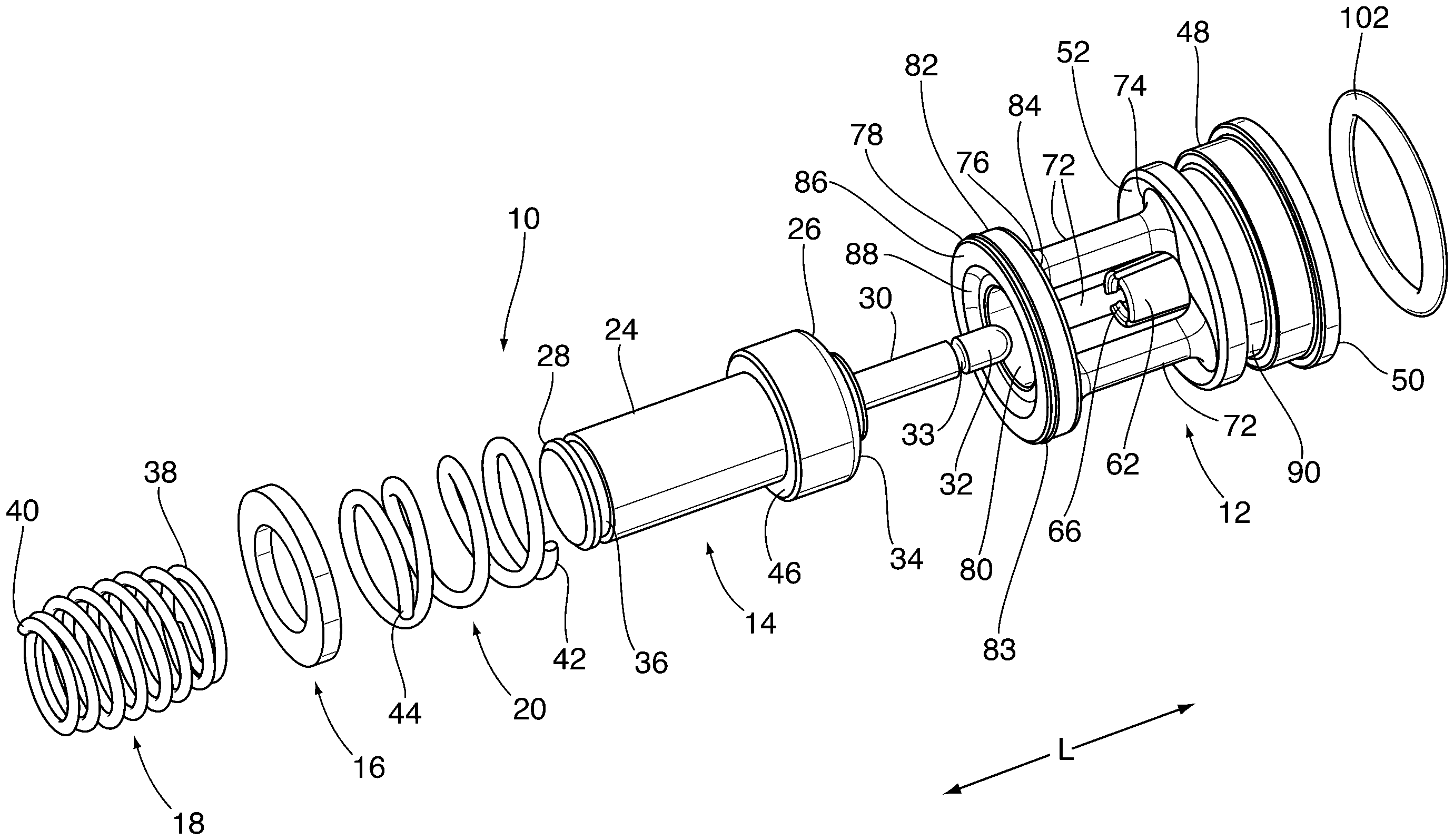
  • 1 eine perspektivische Ansicht ist, die eine Ventilpatronenanordnung nach einer Ausführungsform in einem auseinandergebauten Zustand zeigt;
  • 2 ein mittiger Längsschnitt durch die Ventilpatronenanordnung von 1 ist;
  • 3 eine perspektivische Ansicht der Ventilkappe der Ventilpatronenanordnung von 1 von deren zweitem Ende ist;
  • 4 eine perspektivische Ansicht der Ventilkappe der Ventilpatronenanordnung von 1 von deren erstem Ende ist;
  • 5 ein mittiger Längsschnitt durch die Ventilkappe von 3 und 4 ist;
  • 6 ein Querschnitt durch die Ventilkappe von 3 und 4 ist;
  • 7 ist ein vergrößerter mittiger Längsschnitt durch die Ventilpatronenanordnung, die den Kolben des Stellglieds getrennt vom Hülsenabschnitt der Ventilkappe zeigt;
  • 8 ist ein vergrößerter mittiger Längsschnitt durch die Ventilpatronenanordnung, die den Kolben des Stellglieds teilweise im Hülsenabschnitt der Ventilkappe aufgenommen zeigt;
  • 9 ist ein vergrößerter mittiger Längsschnitt durch die Ventilpatronenanordnung, die den Kolben des Stellglieds vollständig im Hülsenabschnitt der Ventilkappe aufgenommen zeigt;
  • 10 ein mittiger Längsschnitt durch ein die Ventilpatronenanordnung von 1 enthaltendes Ventil ist;
  • 11 ein mittiger Längsschnitt durch ein eine Ventilpatronenanordnung gemäß einer zweiten Ausführungsform enthaltendes Ventil ist; und
  • 12 eine perspektivische Ansicht der Ventilkappe der Ventilpatronenanordnung gemäß der zweiten Ausführungsform ist.
Exemplary embodiments of the present disclosure will now be described by way of example with reference to the accompanying drawings, of which:
  • 1 Fig. 3 is a perspective view showing a valve cartridge assembly according to an embodiment in a disassembled state;
  • 2 a central longitudinal section through the valve cartridge assembly of 1 is;
  • 3 FIG. 3 is a perspective view of the valve cap of the valve cartridge assembly of FIG 1 from the second end of which is;
  • 4th FIG. 3 is a perspective view of the valve cap of the valve cartridge assembly of FIG 1 from the first end of which is;
  • 5 a central longitudinal section through the valve cap of 3 and 4th is;
  • 6th a cross section through the valve cap of 3 and 4th is;
  • 7th Figure 3 is an enlarged, longitudinal, central section through the valve cartridge assembly showing the actuator piston separated from the sleeve portion of the valve cap;
  • 8th Fig. 3 is an enlarged central longitudinal section through the valve cartridge assembly showing the actuator piston partially received in the sleeve portion of the valve cap;
  • 9 Fig. 3 is an enlarged central longitudinal section through the valve cartridge assembly showing the actuator piston fully received in the sleeve portion of the valve cap;
  • 10 a central longitudinal section through the valve cartridge assembly of 1 containing valve is;
  • 11 Figure 3 is a central longitudinal section through a valve incorporating a valve cartridge assembly according to a second embodiment; and
  • 12 Figure 3 is a perspective view of the valve cap of the valve cartridge assembly according to the second embodiment.

AUSFÜHRLICHE BESCHREIBUNGDETAILED DESCRIPTION

Die Zeichnungen stellen eine Ventilpatronenanordnung 10, umfassend eine Ventilkappe 12, ein Ventilstellglied 14, ein erstes Ventilelement 16, ein zweites Ventilelement 34, ein erstes Federelement 18 und optional ein zweites Federelement 20 dar. Diese Komponenten werden in 1 in einem auseinandergebauten Zustand gezeigt.The drawings illustrate a valve cartridge assembly 10 , comprising a valve cap 12 , a valve actuator 14th , a first valve element 16 , a second valve element 34 , a first spring element 18th and optionally a second spring element 20th These components are used in 1 shown in a disassembled state.

Die Ventilpatronenanordnung 10 definiert eine Längsachse L. Wie hier verwendet, sind Begriffe wie „axial“ und „längs“ so zu verstehen, dass sie entlang oder parallel zur Längsachse L bedeuten.The valve cartridge assembly 10 defines a longitudinal axis L. As used herein, terms such as “axial” and “longitudinal” are to be understood to mean along or parallel to the longitudinal axis L.

Das Ventilstellglied 14 umfasst einen allgemein zylindrisch geformten Stellgliedkörper 24 mit einem ersten Ende 26 und einem zweiten Ende 28, die entlang der Längsachse L voneinander beabstandet sind. Das Ventilstellglied 14 umfasst ferner einen Kolben 30, der sich vom ersten Ende 26 des Stellgliedkörpers 24 axial erstreckt, wobei der Kolben 30 entlang der Längsachse L aus- und einfahrbar ist. Sofern weiter unten nicht anders angegeben zeigt die Zeichnung den Kolben 30 in seiner eingefahrenen Position. Der Kolben 30 umfasst einen zylindrischen Metallschaft, aufweisend ein distales Ende 32, das abgerundet sein kann, und aufweisend eine ringförmige Nut 33 an seiner Außenfläche, aus Gründen, die nachstehend erläutert werden. Die ringförmige Nut 33 kann sich nahe dem distalen Ende 32 des Kolbens 30 befinden.The valve actuator 14th includes a generally cylindrically shaped actuator body 24 with a first ending 26th and a second end 28 which are spaced from one another along the longitudinal axis L. The valve actuator 14th further comprises a piston 30th that extends from the first end 26th of the actuator body 24 axially extending, the piston 30th can be extended and retracted along the longitudinal axis L. Unless otherwise stated below, the drawing shows the piston 30th in its retracted position. The piston 30th comprises a cylindrical metal shaft having a distal end 32 , which can be rounded, and having an annular groove 33 on its outer surface, for reasons explained below. The annular groove 33 can be near the distal end 32 of the piston 30th are located.

Das zweite Ventilelement 34 ist am ersten Ende 26 des Stellgliedkörpers 24 vorgesehen und ist in der vorliegenden Ausführungsform integral mit dem Stellgliedkörper 24 ausgebildet und weist an dessen ersten Ende 26 eine ringförmige Oberfläche auf. Das erste Ende 26 des Stellgliedkörpers 24 kann vergrößert sein, um den Durchmesser der zweiten Ventilscheibe 34 aufzunehmen. Es sei jedoch verstanden, dass das zweite Ventilelement 34 stattdessen eine separate Ventilscheibe umfassen kann, in Form einer ringförmigen Unterlegscheibe ähnlich der in der US-Patentanmeldung Nr. US 2016/0349770 A1 des gemeinsamen Inhabers beschriebenen zweiten Ventilscheibe. Das zweite Ende 28 des Stellgliedkörpers 24 weist aus Gründen, die nachstehend erläutert werden, eine ringförmige Nut 36 auf.The second valve element 34 is at the first end 26th of the actuator body 24 and is integral with the actuator body in the present embodiment 24 formed and has at its first end 26th an annular surface. The first ending 26th of the actuator body 24 can be enlarged by the diameter of the second valve disc 34 record. It should be understood, however, that the second valve element 34 may instead include a separate valve disc, in the form of an annular washer similar to that described in U.S. Patent Application No. US 2016/0349770 A1 of the joint owner described second valve disc. The second ending 28 of the actuator body 24 has an annular groove for reasons explained below 36 on.

Das Ventilstellglied 14 in der vorliegenden Ausführungsform ist ein Thermo-Stellglied und kann manchmal auch als Wärmemotor oder Wachsmotor bezeichnet werden. Der Stellgliedkörper 24 enthält ein thermisch empfindliches Material (nicht gezeigt), welches sich beim Erwärmen über eine Schwellentemperatur ausdehnt und sich beim Abkühlen unter eine Schwellentemperatur zusammenzieht. Das thermisch empfindliche Material kann ein Wachsmaterial umfassen. Ausdehnen des thermisch empfindlichen Materials bewirkt, dass der Kolben 30 axial ausfährt und Zusammenziehen des thermisch empfindlichen Materials ermöglicht, dass der Kolben 30 einfährt. Der Stellgliedkörper 24 wirkt daher als eine Temperaturerfassungsvorrichtung, die auf Temperaturänderungen in einem durch das Ventil fließenden Fluid reagiert.The valve actuator 14th in the present embodiment is a thermal actuator and can sometimes be referred to as a heat engine or a wax engine. The actuator body 24 contains a thermally sensitive material (not shown) which expands when heated above a threshold temperature and contracts when cooled below a threshold temperature. The thermally sensitive material can comprise a wax material. Expansion of the thermally sensitive material causes the piston 30th axially extends and contraction of the thermally sensitive material allows the piston 30th comes in. The actuator body 24 therefore acts as a temperature sensing device responsive to temperature changes in a fluid flowing through the valve.

Alternativ kann das Ventilstellglied 14 ein elektronisches Stellglied umfassend, das den Kolben 30 als Antwort auf von einem Temperatursensor erhaltene Signale ein- und ausfährt, das sich andernorts im Fahrzeug befinden kann und das die Temperatur einer Fahrzeugkomponente und/oder eines Fluids erkennt.Alternatively, the valve actuator 14th an electronic actuator comprising the piston 30th moves in and out in response to signals received from a temperature sensor that may be located elsewhere in the vehicle and that detects the temperature of a vehicle component and / or a fluid.

Das erste Ventilelement 16 wird als eine getrennte Komponente in Form einer ringförmigen Scheibe oder Unterlegscheibe, die verschiebbar über dem zweiten Ende 28 des Stellgliedkörpers 24 zwischen dem ersten und dem zweiten Federelement 18, 20 aufgenommen ist, gezeigt. In einigen Ausführungsformen kann das erste Ventilelement 16 jedoch starr am zweiten Ende 28 des Stellgliedkörpers 24 befestigt sein, und kann integral mit diesem ausgebildet sein.The first valve element 16 comes as a separate component in the form of an annular washer or washer that slides over the second end 28 of the actuator body 24 between the first and the second spring element 18th , 20th is recorded. In some embodiments, the first valve element 16 but rigid at the second end 28 of the actuator body 24 and may be formed integrally therewith.

Das erste Federelement 18 umfasst eine Schraubenfeder, welche auch als Rückstellfeder bezeichnet werden kann. Das erste Federelement 18 weist ein proximales Ende 38 auf, das in der ringförmigen Nut 36 am zweiten Ende 28 des Ventilkörpers 24 gesichert ist, und an einem zweiten distalen Ende 40, das sich von dem zweiten Ende 28 des Ventilkörpers 24 axial weg erstreckt. Wie nachstehend näher erläutert wird, ist das erste Federelement 18 durch den Stellgliedkörper 24 axial zusammengedrückt, wenn der Kolben 30 ausgefahren ist, und drängt den Kolben 30 zurück in seine eingefahrene Position, beispielsweise wenn das thermisch empfindliche Material im Stellgliedkörper 24 in seinen ursprünglichen zusammengezogenen Zustand zurückkehrt.The first spring element 18th comprises a helical spring, which can also be referred to as a return spring. The first spring element 18th has a proximal end 38 on that in the annular groove 36 at the second end 28 of the valve body 24 is secured, and at a second distal end 40 that extends from the second end 28 of the valve body 24 axially extends away. As explained in more detail below, the first is Spring element 18th through the actuator body 24 axially compressed when the piston 30th is extended and pushes the piston 30th back to its retracted position, such as when the thermally sensitive material is in the actuator body 24 returns to its original contracted state.

Im Querschnitt von 2 ist ersichtlich, dass der Durchmesser der Öffnung im ersten Ventilelement 16 kleiner als der Außendurchmesser des ersten proximalen Endes 38 des ersten Federelements 18 ist und dass das erste Federelement 18 daher auch das erste Ventilelement 16 daran hindert, sich vom Stellgliedkörper 24 zu trennen.In the cross section of 2 it can be seen that the diameter of the opening in the first valve element 16 smaller than the outer diameter of the first proximal end 38 of the first spring element 18th is and that the first spring element 18th hence the first valve element 16 prevents it from moving away from the actuator body 24 to separate.

Das zweite Federelement 20 umfasst eine Schraubenfeder, die auch als Vorrangfeder bezeichnet werden kann. Das zweite Federelement 20 erstreckt sich um die Außenfläche des Stellgliedkörpers 24 und weist ein erstes Ende 42, das eine axiale Schulter 46 des vergrößerten ersten Endabschnitts des Stellgliedkörpers 24 kontaktiert, und ein zweites Ende, das das erste Ventilelement 16 kontaktiert. Das zweite Federelement 20 steht unter Kompressionsdruck und drängt somit das erste Ventilelement 16 zum zweiten Ende 28 des Stellgliedkörpers 24 hin. Das zweite Federelement 20 ermöglicht auch, dass das erste Ventilelement 16 unter bestimmten Betriebsbedingungen zum ersten Ende 26 des Stellgliedkörpers 24 gedrängt wird, beispielsweise wenn ein hoher Fluiddruck auf das erste Ventilelement 16 mit einer Kraft wirkt, die zum Zusammendrücken des zweiten Federelements 20 ausreicht. Wird eine Druckentlastung nicht erwünscht oder benötigt, kann das erste Ventilelement 16 stattdessen starr am zweiten Ende 28 des Stellgliedkörpers 24 befestigt sein, oder es kann integral mit diesem ausgebildet sein, auf ähnliche Weise wie bei dem zweiten Ventilelement 34.The second spring element 20th includes a helical spring, which can also be referred to as a priority spring. The second spring element 20th extends around the outer surface of the actuator body 24 and has a first end 42 that has an axial shoulder 46 of the enlarged first end portion of the actuator body 24 contacted, and a second end that the first valve element 16 contacted. The second spring element 20th is under compression pressure and thus pushes the first valve element 16 to the second end 28 of the actuator body 24 down. The second spring element 20th also allows the first valve element 16 under certain operating conditions to the first end 26th of the actuator body 24 is urged, for example when a high fluid pressure on the first valve element 16 acts with a force that compresses the second spring element 20th sufficient. If pressure relief is not desired or required, the first valve element can 16 instead rigid at the second end 28 of the actuator body 24 or it may be formed integrally therewith, in a similar manner to the second valve element 34 .

Die Ventilkappe 12 erfüllt mehrere Funktionen und weist mehrere Komponenten auf, die nun nachstehend beschrieben werden.The valve cap 12 performs several functions and has several components, which will now be described below.

Die Ventilkappe 12 weist eine allgemein zylindrische Ventilverschlusskappe 48 mit einem ersten Ende 50 und einem zweiten Ende 52 auf. Das erste Ende 50 bildet eine Außenfläche der Ventilpatronenanordnung 10 und das erste Ende 50 ist, wie weiter unten diskutiert wird, von der Außenseite eines Ventilgehäuses, in das die Ventilpatronenanordnung 10 eingesetzt wird, zugänglich. Die Ventilverschlusskappe 48 weist eine zylindrische Außenfläche auf, die zur Aufnahme eines elastischen Dichtungselements 102 in Form eines O-Rings mit einer ringförmigen Nut 90 versehen ist, wie weiter unten beschrieben wird.The valve cap 12 has a generally cylindrical valve cap 48 with a first ending 50 and a second end 52 on. The first ending 50 forms an outer surface of the valve cartridge assembly 10 and the first ending 50 is, as discussed below, from the outside of a valve housing into which the valve cartridge assembly 10 is used, accessible. The valve cap 48 has a cylindrical outer surface which is used to receive an elastic sealing element 102 in the form of an O-ring with an annular groove 90 as described below.

Das erste Ende 50 der Ventilverschlusskappe 48 ist mit einer oder mehreren Vertiefungen 54 versehen, die zum Eingriff mit einem Werkzeug zum Einsetzen und Entfernen der Ventilpatronenanordnung 10 aus einem Gehäuse geformt sind. Der in 4 gezeigten Vertiefungen 54 werden keilförmig und mittig um die Mitte der das erste Ende 50 definierenden kreisförmigen Stirnfläche angeordnet dargestellt, wobei die Vertiefungen 54 durch schmale Stege 56 voneinander getrennt sind. Die Vertiefungen 54 sind von einer flachen, ringförmigen Fläche 58 umgeben. Zusätzlich zum Vorsehen eines Eingriffs mit einem Installationswerkzeug dienen die Vertiefungen auch dazu, die Materialstärke der Ventilkappe 12, die typischerweise aus Kunststoff geformt ist, zu reduzieren. Diese Reduzierung der Materialstärke reduziert Gewicht und Materialkosten und die Stärkereduzierung ist bei 60 in 5 und, durch Vergleichen der vollen Stärke (Stärke A) der Ventilverschlusskappe 48 mit der reduzierten Stärke (Stärke B) in den Vertiefungen 54 zu sehen.The first ending 50 the valve cap 48 is with one or more wells 54 provided for engagement with a tool for inserting and removing the valve cartridge assembly 10 are formed from a housing. The in 4th depressions shown 54 will be wedge shaped and centered around the center of the first end 50 defining circular end face shown arranged, the depressions 54 through narrow webs 56 are separated from each other. The depressions 54 are of a flat, annular surface 58 surround. In addition to providing engagement with an installation tool, the depressions also serve to reduce the material thickness of the valve cap 12 , which is typically molded from plastic. This reduction in material thickness reduces weight and material cost, and the thickness reduction is at 60 in 5 and, by comparing the full thickness (thickness A) of the valve cap 48 with the reduced strength (strength B) in the depressions 54 to see.

Das zweite Ende 52 der Ventilverschlusskappe 48 ist mit einem mittigen, sich axial erstreckenden Hülsenabschnitt 62 versehen, der dazu angepasst ist, ein distales Ende 32 des Kolbens 30 formschlüssig aufzunehmen. Der Hülsenabschnitt 62 weist eine allgemein zylindrische Innenwandfläche auf, die mit einer von der Innenwandfläche in den hohlen Innenraum des Hülsenabschnitts 62 hervorstehenden ringförmigen Wulst 64 versehen ist. Wie in 8 gezeigt, ist die ringförmige Wulst 64 so geformt und dimensioniert, dass sie mit enger Passung in der ringförmigen Nut 33 nahe dem distalen Ende 32 des Kolbens 30 aufgenommen wird.The second ending 52 the valve cap 48 is with a central, axially extending sleeve portion 62 which is adapted to have a distal end 32 of the piston 30th to be positively received. The sleeve section 62 has a generally cylindrical inner wall surface that connects with one of the inner wall surface into the hollow interior of the sleeve portion 62 protruding annular bead 64 is provided. As in 8th shown is the annular bead 64 Shaped and sized to fit snugly in the annular groove 33 near the distal end 32 of the piston 30th is recorded.

Aufgrund des Formschlusses der Wulst 64 und der Nut 33 hält der Kolben 30 einem Herausziehen aus dem Hülsenabschnitt 62 stand und daher verhindert der Formschluss der Wulst 64 und der Nut 33 ein Trennen der Ventilpatronenanordnung 10 in zwei getrennte Komponenten. Dadurch werden Herstellung und Transport (Logistik) vereinfacht, insbesondere wenn die Ventilpatronenanordnung als eine getrennte Komponente hergestellt und an Dritte versandt wird, wo sie in ein Ventilgehäuse eingesetzt wird. Weiterhin ist das distale Ende 32 des Kolbens 30 mit enger Passung im Hülsenabschnitt 62 aufgenommen. Sowohl der Kolben 30 als auch der Hülsenabschnitt 62 sind axial ausgerichtet und die enge Passung des Kolbens 30 im Hülsenabschnitt 62 unterstützt das Aufrechterhalten der axialen Gesamtausrichtung der Ventilpatronenanordnung 10, die zum einfachen Einsetzen der Ventilpatronenanordnung 10 in ein Gehäuse erforderlich ist.Due to the form fit of the bead 64 and the groove 33 holds the piston 30th pulling out of the sleeve section 62 stood and therefore prevents the form fit of the bead 64 and the groove 33 separating the valve cartridge assembly 10 into two separate components. This simplifies manufacture and transport (logistics), in particular if the valve cartridge assembly is manufactured as a separate component and shipped to a third party, where it is inserted into a valve housing. Furthermore is the distal end 32 of the piston 30th with a tight fit in the sleeve section 62 recorded. Both the piston 30th as well as the sleeve section 62 are axially aligned and the close fit of the piston 30th in the sleeve section 62 assists in maintaining the overall axial alignment of the valve cartridge assembly 10 for easy insertion of the valve cartridge assembly 10 in a housing is required.

7 bis 9 zeigen wie das distale Ende 32 des Kolbens 30 während des Zusammenbaus der Ventilpatronenanordnung 10 in den Hülsenabschnitt 62 eingesetzt wird. Wie in 7 gezeigt, ist das distale Ende 32 des Kolbens 30 abgerundet und der Hülsenabschnitt 62 weist ein geweitetes offenes Ende 66 auf, um das Ausrichten und Einsetzen des Kolbens 30 in den Hülsenabschnitt 62 zu unterstützen. 7th to 9 show how the distal end 32 of the piston 30th during assembly of the valve cartridge assembly 10 in the sleeve section 62 is used. As in 7th shown is the distal end 32 of the piston 30th rounded and the sleeve section 62 has a flared open end 66 on to aligning and inserting the piston 30th in the sleeve section 62 to support.

Wenn der Kolben 30 so weit wie in 8 gezeigt im Hülsenabschnitt 62 eingesetzt ist, kommt das distale Ende 32 des Kolbens 30 in Kontakt mit der ringförmigen Wulst 64 und ein Schieben des distalen Endes 32 über die Wulst 64 bewirkt ein Biegen des Hülsenabschnitts 62 nach außen, wie durch die gekrümmten Pfeile in 8 gezeigt. Das Biegen des Hülsenabschnitts 62 nach außen wird ermöglicht durch Versehen des Hülsenabschnitts mit einer Mehrzahl von axialen Schlitzen 68, die sich von einem offenen Ende 66 des Hülsenabschnitts 62 zum zweiten Ende 52 der Ventilverschlusskappe 48 erstrecken. Die Schlitze 68 teilen die Wand des Hülsenabschnitts 62 in eine Mehrzahl von sich axial erstreckenden Fingern 70 auf, welche in radialer Richtung nach innen und nach außen beim Einsetzen des Kolbens 30 flexibel sind. In der dargestellten Ausführungsform sind drei Schlitze 68 und drei Finger 70 vorhanden; es sei jedoch verstanden, dass der Hülsenabschnitt 62 zwei Schlitze 68 und zwei Finger 70 oder mehr als drei Schlitze 68 und Finger 70 aufweisen kann.When the piston 30th as far as in 8th shown in the sleeve section 62 is inserted, comes the distal end 32 of the piston 30th in contact with the annular bead 64 and pushing the distal end 32 over the bead 64 causes the sleeve section to bend 62 outwards, as indicated by the curved arrows in 8th shown. The bending of the sleeve section 62 outward is made possible by providing the sleeve section with a plurality of axial slots 68 that extends from an open end 66 of the sleeve section 62 to the second end 52 the valve cap 48 extend. The slots 68 divide the wall of the sleeve section 62 into a plurality of axially extending fingers 70 on which in the radial direction inward and outward when inserting the piston 30th are flexible. In the illustrated embodiment there are three slots 68 and three fingers 70 available; it should be understood, however, that the sleeve portion 62 two slots 68 and two fingers 70 or more than three slots 68 and fingers 70 may have.

Wie in 9 gezeigt, wenn das distale Ende 32 des Kolbens 30 ausreichend weit eingesetzt ist, dass die ringförmige Nut 33 im Kolben 30 an der ringförmigen Wulst 64 ausgerichtet ist, biegen sich die Finger 70 radial nach innen und die ringförmige Wulst 64 wird in der ringförmigen Nut 33 aufgenommen, wodurch der Formschluss zwischen dem Kolben 30 und dem Hülsenabschnitt 62 hergestellt wird.As in 9 shown when the distal end 32 of the piston 30th is inserted sufficiently far that the annular groove 33 in the piston 30th on the annular bead 64 is aligned, the fingers bend 70 radially inward and the annular bead 64 is in the annular groove 33 added, creating the form fit between the piston 30th and the sleeve section 62 will be produced.

Das zweite Ende 52 der Ventilverschlusskappe 48 ist ebenfalls mit einer Mehrzahl von sich axial erstreckenden Streben 72 versehen, die in Umfangsrichtung um den Hülsenabschnitt 62 angeordnet sind. Wie unten weiter diskutiert, weist jede der Streben 72 ein am zweiten Ende 52 der Ventilverschlusskappe 48 befestigtes erstes Ende 74 und ein am ringförmigen Endabschnitt 78 der Ventilkappe 12 befestigtes zweites Ende 76 auf.The second ending 52 the valve cap 48 is also with a plurality of axially extending struts 72 provided in the circumferential direction around the sleeve portion 62 are arranged. As discussed further below, each of the struts 72 one at the second end 52 the valve cap 48 attached first end 74 and one at the annular end portion 78 the valve cap 12 attached second end 76 on.

Es sei verstanden, dass die Zwischenräume zwischen den Streben 72 Fluidströmungsdurchgänge vorsehen und die Ventilpatronenanordnung 10 die Dimensionen und die Anzahl der Streben 72 minimiert, um die Zwischenräume zwischen den Streben 72 so groß wie möglich zu gestalten, um den Druckabfall des Fluids beim Durchströmen des Ventils, insbesondere durch die Ventilkappe 12 zu minimieren. Aus 6 ist ersichtlich, dass die Ventilkappe 12 drei Streben 72 aufweist, die in Umfangsrichtung um etwa 120 Grad voneinander beabstandet sind, und dass die Zwischenräume zwischen den Streben 72 eine wesentlich größere Fläche aufweisen als die Streben 72 selbst.It should be understood that the spaces between the struts 72 Provide fluid flow passages and the valve cartridge assembly 10 the dimensions and number of struts 72 minimized to the spaces between the struts 72 to be made as large as possible in order to reduce the pressure drop of the fluid as it flows through the valve, in particular through the valve cap 12 to minimize. Out 6th it can be seen that the valve cap 12 three struts 72 which are spaced from one another in the circumferential direction by about 120 degrees, and that the spaces between the struts 72 have a much larger area than the struts 72 even.

Der ringförmige Endabschnitt 78 der Ventilkappe 12 weist eine Ringform auf mit einer Mittelöffnung 80, die ein Strömen von Fluid zwischen auf gegenüberliegenden Seiten des ringförmigen Endabschnitts 78 angeordneten Bereichen der Ventilpatronenanordnung 10 ermöglicht. Der ringförmige Endabschnitt 78 weist zudem eine im Wesentlichen zylindrische Außenfläche 82 auf, die angepasst ist, eine weitgehende Dichtung mit einer Innenfläche eines Ventilgehäuses zu bilden, und die mit einer ringförmigen Dichtungslippe versehen sein kann.The annular end portion 78 the valve cap 12 has an annular shape with a central opening 80 allowing fluid to flow between on opposite sides of the annular end portion 78 arranged areas of the valve cartridge assembly 10 enables. The annular end portion 78 also has a substantially cylindrical outer surface 82 which is adapted to form a substantial seal with an inner surface of a valve housing and which can be provided with an annular sealing lip.

Der ringförmige Endabschnitt 78 weist eine erste Seite 84 auf, an der die zweite Seite 76 der Streben 72 befestigt ist, und eine zweite Seite 86, die einen ringförmigen Ventilsitz 88 definiert, der angepasst ist zum Bilden einer fluiddichten Dichtung mit dem zweiten Ventilelement 34, welches mit dem Stellgliedkörper 24 integral ausgebildet ist. Der ringförmige Ventilsitz 88 kann relativ zur zweiten Seite 86 vertieft sein. Ferner sitzt das zweite Ventilelement 34 im neutralen (Niedertemperatur) Zustand der Ventilpatronenanordnung 10, bei dem sich der Kolben 30 in der in 2 gezeigten nicht betätigten, eingefahrenen Position befindet, auf dem Ventilsitz 86 und das zweite Ventilelement 34 ist, da der Ventilsitz 86 vertieft ist, zumindest teilweise im ringförmigen Endabschnitt aufgenommen, wodurch ein zusätzlicher Kontaktpunkt zwischen der Ventilkappe 12 und dem Ventilstellglied 14 vorgesehen ist, welches bei der axialen Ausrichtung der Ventilpatronenanordnung 10 zusätzlich unterstützt. Es sei verstanden, dass der Kolben 30 beim Transport der Ventilpatronenanordnung 10 und beim Einsetzen der Ventilpatronenanordnung 10 in ein Ventilgehäuse typischerweise im nicht betätigten, eingefahrenen Zustand verbleibt.The annular end portion 78 has a first side 84 on to the second side 76 of striving 72 is attached, and a second side 86 that have an annular valve seat 88 that is adapted to form a fluid-tight seal with the second valve element 34 which is connected to the actuator body 24 is integrally formed. The annular valve seat 88 can be relative to the second side 86 be absorbed. The second valve element is also seated 34 in the neutral (low temperature) state of the valve cartridge assembly 10 where the piston 30th in the in 2 unactuated, retracted position shown is on the valve seat 86 and the second valve element 34 is as the valve seat 86 is recessed, at least partially received in the annular end portion, creating an additional point of contact between the valve cap 12 and the valve actuator 14th is provided, which in the axial alignment of the valve cartridge assembly 10 additionally supported. It should be understood that the piston 30th when transporting the valve cartridge assembly 10 and when inserting the valve cartridge assembly 10 typically remains in a valve housing in the non-actuated, retracted state.

10 zeigt die Ventilpatronenanordnung 10 nach deren Einsetzen in ein Ventilgehäuse 100. Das Ventilgehäuse 100 weist eine hohle Ventilkammer 104 und ein offenes Ende 106 auf, durch das die Ventilpatronenanordnung 10 in die Kammer 104 eingesetzt wird. Wenn die Ventilpatronenanordnung 10 eingesetzt wurde, ist sie durch eine elastische Federklemme 108 verriegelt, die ein C-förmiger Metallring sein kann, dessen äußerer Abschnitt in einer ringförmigen Nut 110 knapp innerhalb des offenen Endes 106 aufgenommen ist und dessen innerer Abschnitt die flache, ringförmige Fläche 58 am ersten Ende 50 der Ventilverschlusskappe 48 kontaktiert. 10 shows the valve cartridge assembly 10 after inserting them into a valve housing 100 . The valve body 100 has a hollow valve chamber 104 and an open end 106 through which the valve cartridge assembly 10 into the chamber 104 is used. When the valve cartridge assembly 10 was inserted, it is through an elastic spring clip 108 locked, which may be a C-shaped metal ring, its outer portion in an annular groove 110 just inside the open end 106 is added and the inner portion of the flat, annular surface 58 at the first end 50 the valve cap 48 contacted.

Die Ventilkammer 104 weist eine allgemein zylindrische Innenwand auf, gegen die die äußeren zylindrischen Flächen der Ventilverschlusskappe 48 und der ringförmige Endabschnitt 78 abgedichtet sind. Die Dichtung zwischen der Ventilverschlusskappe 48 und dem Gehäuse 100 ist mithilfe des O-Rings 102, welcher in der ringförmigen Nut 90 der Ventilverschlusskappe 48 aufgenommen ist, fluiddicht gemacht. Zudem steht die ringförmige Dichtungslippe 83 der Außenfläche 82 des ringförmigen Endabschnitts in Eingriff mit der zylindrischen Innenwand der Ventilkammer 104, um eine Leckage des Fluids um die Außenkanten des ringförmigen Endabschnitts 78 zu verhindern.The valve chamber 104 has a generally cylindrical inner wall against which the outer cylindrical surfaces of the valve closure cap 48 and the annular end portion 78 are sealed. The seal between the valve cap 48 and the case 100 is by means of the O-ring 102 which is in the annular groove 90 the valve cap 48 is added, made fluid-tight. In addition, the ring-shaped Sealing lip 83 the outer surface 82 of the annular end portion in engagement with the cylindrical inner wall of the valve chamber 104 to prevent leakage of the fluid around the outer edges of the annular end portion 78 to prevent.

Die Ventilkammer 104 kann eine abgestufte Bohrung mit einer Mehrzahl von Durchmesserverringerungen umfassen, die auf der Innenseite des offenen Endes 106 oder optional bündig mit dem offenen Ende 106 angeordnet ist. Eine der Durchmesserverringerungen sieht eine ringförmige Schulter 112 vor, die einen Ventilsitz für das erste Ventilelement 16 definiert. Im neutralen, nicht betätigten Zustand der Ventilpatronenanordnung 10 ist das erste Ventilelement 16 von der ersten ringförmigen Schulter 112 beabstandet. Wenn die Ventilpatronenanordnung 10 jedoch betätigt wird und der Kolben 30 ausgefahren wird, bewegen sich der Stellgliedkörper 24 und das erste Ventilelement 16 in 10 nach links, bis das erste Ventilelement 16 auf der ersten ringförmigen Schulter 112 sitzt. Es sei verstanden, dass die Bewegung des Stellgliedkörpers 24 nach links auch bewirkt, dass sich das zweite Ventilelement 34 außer Eingriff mit dem Ventilsitz 88 des ringförmigen Endabschnitts 78 bewegt.The valve chamber 104 may include a stepped bore with a plurality of diameter reductions formed on the inside of the open end 106 or optionally flush with the open end 106 is arranged. One of the diameter reductions sees an annular shoulder 112 before having a valve seat for the first valve element 16 Are defined. In the neutral, non-actuated state of the valve cartridge assembly 10 is the first valve element 16 from the first annular shoulder 112 spaced. When the valve cartridge assembly 10 however is actuated and the piston 30th is extended, the actuator body will move 24 and the first valve element 16 in 10 to the left until the first valve element 16 on the first annular shoulder 112 sits. It should be understood that the movement of the actuator body 24 to the left also causes the second valve element 34 out of engagement with the valve seat 88 of the annular end portion 78 emotional.

Eine weitere der Durchmesserverringerungen in der Ventilkammer 104 sieht eine zweite ringförmige Schulter 114 vor, die eine Stützfläche für das zweite distale Ende 40 des ersten Federelements 18, d.h. die Rückstellfeder, definiert. Das erste Federelement 18 steht unter Kompressionsdruck zwischen der zweiten ringförmigen Schulter 114 und dem zweiten Ende 28 des Stellgliedkörpers 24, um das erste Ventilelement 16 von der ersten ringförmigen Schulter 112 wegzudrängen.Another one of the diameter reductions in the valve chamber 104 sees a second annular shoulder 114 before having a support surface for the second distal end 40 of the first spring element 18th , ie the return spring defined. The first spring element 18th is under compression pressure between the second annular shoulder 114 and the second end 28 of the actuator body 24 to the first valve element 16 from the first annular shoulder 112 to push away.

Das Ventilgehäuse 100 weist ferner eine Mehrzahl von Ventilöffnungen 116, 118, 120, 122 auf, durch die Fluid in die und aus der Ventilkammer 104 ein- bzw. austreten kann. Die Anordnungen dieser Öffnungen sind nur exemplarisch und können je nach spezifischer Anwendung abweichen. Es sei zu verstehen, dass die Ventilöffnung 122, die einen Teil der das Ventilgehäuse 104 definierenden abgestuften Bohrung bildet, als Druckentlastungs- oder Druck-Bypass-Kanal dienen kann, je nach spezifischer Anwendung.The valve body 100 also has a plurality of valve openings 116 , 118 , 120 , 122 on, through which fluid in and out of the valve chamber 104 can enter or exit. The arrangements of these openings are only exemplary and may vary depending on the specific application. It should be understood that the valve opening 122 that is part of the valve body 104 defining stepped bore forms, can serve as a pressure relief or pressure bypass channel, depending on the specific application.

Es sei verstanden, dass das Gehäuse 100 lediglich als Beispiel eines Gehäuses gezeigt wird und dass die Ventilpatronenanordnung 10 für eine große Bandbreite an Gehäusekonfigurationen mit einer Reihe von Öffnungskonfigurationen anpassbar ist. Es sei ebenfalls verstanden, dass das Gehäuse 100 eine getrennte Komponente eines Fahrzeug-Fluidzirkulationssystems sein kann oder in eine weitere Fahrzeugkomponente, etwa einen Wärmetauscher, Getriebe oder eine andere Antriebsstrangkomponente usw., integriert sein kann.It should be understood that the housing 100 is shown only as an example of a housing and that the valve cartridge assembly 10 is adaptable to a wide range of enclosure configurations with a range of opening configurations. It should also be understood that the housing 100 may be a separate component of a vehicle fluid circulation system, or may be integrated with another vehicle component such as a heat exchanger, transmission, or other powertrain component, etc.

Die oben beschriebene Ventilpatronenanordnung 10 beinhaltet ein Paar Ventilelemente 16, 34, die angepasst sind zum Abdichten mit dem Ventilsitz 112 (im Gehäuse 100 ausgebildet) bzw. 88 (in der Ventilkappe ausgebildet). Es ist möglich, zumindest einige der oben beschriebenen Vorteile in einer einfacheren Ventilstruktur mit einer einfacheren Struktur, und nur ein einziges Ventilelement und Ventilsitz enthaltend, vorzusehen. Eine solche Ventilpatronenanordnung 130 wird nun unten beschrieben. In der folgenden Beschreibung werden ähnlichen Elemente mit gleichen Bezugszeichen beschrieben.The valve cartridge assembly described above 10 includes a pair of valve elements 16 , 34 that are adapted to seal with the valve seat 112 (in the case 100 trained) or 88 (formed in the valve cap). It is possible to provide at least some of the advantages described above in a simpler valve structure having a simpler structure and including only a single valve element and valve seat. Such a valve cartridge assembly 130 will now be described below. In the following description, similar elements are described with the same reference numerals.

11 zeigt eine Querschnittsansicht einer in einem Gehäuse 100 aufgenommenen Ventilpatronenanordnung 130. Die Ventilpatronenanordnung 130 weist eine Ventilkappe 12, ein Ventilstellglied 14, ein erstes Ventilelement 16 und ein erstes Federelement 18 auf, das als Rückstellfeder dient. 11 Figure 13 shows a cross-sectional view of one in a housing 100 recorded valve cartridge assembly 130 . The valve cartridge assembly 130 has a valve cap 12 , a valve actuator 14th , a first valve element 16 and a first spring element 18th on, which serves as a return spring.

Das Ventilstellglied 14 ist ähnlich dem der oben beschriebenen Anordnung 10, aufweisend einen Stellgliedkörper 24 mit einem ersten Ende 26 und einem zweiten Ende 28, die entlang der Längsachse L voneinander beabstandet sind. Das Ventilstellglied 14 umfasst ferner einen Kolben 30, der sich vom ersten Ende 26 des Stellgliedkörpers 24 axial erstreckt, wobei der Kolben 30 entlang der Längsachse L aus- und einfahrbar ist, wobei 11 die eingefahrene Position zeigt. Der Kolben 30 umfasst einen zylindrischen Metallschaft, aufweisend ein distales Ende 32, das abgerundet sein kann, und aufweisend eine ringförmige Nut 33 an seiner Außenfläche, nahe dem distalen Ende 32. Das Stellglied 14 kann ein wie oben beschriebenes Thermo-Stellglied sein.The valve actuator 14th is similar to that of the arrangement described above 10 , comprising an actuator body 24 with a first ending 26th and a second end 28 which are spaced from one another along the longitudinal axis L. The valve actuator 14th further comprises a piston 30th that extends from the first end 26th of the actuator body 24 axially extending, the piston 30th can be extended and retracted along the longitudinal axis L, wherein 11 shows the retracted position. The piston 30th comprises a cylindrical metal shaft having a distal end 32 , which can be rounded, and having an annular groove 33 on its outer surface, near the distal end 32 . The actuator 14th can be a thermal actuator as described above.

Das erste Ventilelement 16 ist starr am zweiten Ende 28 des Stellgliedkörpers 24 befestigt und kann integral mit diesem ausgebildet sein. Das erste Federelement 18 umfasst eine Schraubenfeder, aufweisend ein erstes proximale Ende 38, das in der ringförmigen Nut 36 am zweiten Ende 28 des Ventilkörpers 24 gesichert ist, und ein zweites distales Ende 40, das sich von dem zweiten Ende 28 des Ventilkörpers 24 axial weg erstreckt und in Eingriff mit der zweiten ringförmigen Schulter 114 des Gehäuses 100 steht.The first valve element 16 is rigid at the second end 28 of the actuator body 24 attached and may be formed integrally therewith. The first spring element 18th comprises a coil spring having a first proximal end 38 that is in the annular groove 36 at the second end 28 of the valve body 24 is secured, and a second distal end 40 that extends from the second end 28 of the valve body 24 axially extending away and into engagement with the second annular shoulder 114 of the housing 100 stands.

Die Ventilkappe 12 weist eine allgemein zylindrische Ventilverschlusskappe 48 mit einem ersten Ende 50 und einem zweiten Ende 52 auf, wobei das erste Ende 50 vom ersten offenen Ende 106 des Ventilgehäuses 100 nach außen weist. Die Ventilverschlusskappe 48 weist eine zylindrische Außenfläche auf, die zur Aufnahme eines elastischen Dichtungselements 102 in Form eines O-Rings mit einer ringförmigen Nut 90 versehen ist.The valve cap 12 has a generally cylindrical valve cap 48 with a first ending 50 and a second end 52 on, being the first end 50 from the first open end 106 of the valve body 100 facing outwards. The valve cap 48 has a cylindrical outer surface which is used to receive an elastic sealing element 102 in the form of an O-ring with an annular groove 90 is provided.

Das zweite Ende 52 der Ventilverschlusskappe 48 ist mit einer internen, sich längs erstreckenden Bohrung 132 versehen, die einen mittigen, sich axial erstreckenden Hülsenabschnitt 62 definiert, der dazu angepasst ist, ein distales Ende 32 des Kolbens 30 formschlüssig aufzunehmen. Der Hülsenabschnitt 62 weist eine allgemein zylindrische Innenwandfläche auf, die mit einer von der Innenwandfläche in den hohlen Innenraum des Hülsenabschnitts 62 hervorstehenden ringförmigen Wulst 64 versehen ist, wobei die ringförmige Wust 64 so geformt und dimensioniert ist, dass sie mit enger Passung in die ringförmige Nut 33 nahe dem distalen Ende 32 des Kolbens 30 aufgenommen wird. Die Bohrung 132 der Ventilverschlusskappe 48 kann von einer flachen Vertiefung 134 umgeben sein, die zur Aufnahme des ersten Endes 26 des Stellgliedkörpers 24 angepasst ist.The second ending 52 the valve cap 48 is with an internal, longitudinally extending bore 132 provided which has a central, axially extending sleeve portion 62 which is adapted to have a distal end 32 of the piston 30th to be positively received. The sleeve section 62 has a generally cylindrical inner wall surface that connects with one of the inner wall surface into the hollow interior of the sleeve portion 62 protruding annular bead 64 is provided, wherein the annular bead 64 Is shaped and dimensioned to snugly fit into the annular groove 33 near the distal end 32 of the piston 30th is recorded. The hole 132 the valve cap 48 can from a shallow depression 134 be surrounded to accommodate the first end 26th of the actuator body 24 is adapted.

Das Ventilgehäuse 100 weist eine hohle Ventilkammer 104 auf, in welche die Ventilpatronenanordnung 130 durch das offene Ende 106 eingesetzt wird. Die Ventilpatronenanordnung 130 wird durch eine elastische Federklemme 108 verriegelt, die ein C-förmiger Metallring sein kann, wobei dessen äußerer Abschnitt in einer ringförmigen Nut 110 knapp innerhalb des offenen Endes 106 aufgenommen ist, und dessen innerer Abschnitt das erste Ende 50 der Ventilverschlusskappe 48 kontaktiert. Die Ventilkammer 104 weist eine allgemein zylindrische Innenwand auf, gegen die die äußeren zylindrischen Flächen der Ventilverschlusskappe 48 und der ringförmige Endabschnitt 78 abgedichtet sind. Die Dichtung zwischen der Ventilverschlusskappe 48 und dem Gehäuse 100 ist mithilfe des O-Rings 102, welcher in der ringförmigen Nut 90 der Ventilverschlusskappe 48 aufgenommen ist, fluiddicht gemacht. Die Ventilkammer 104 umfasst eine abgestufte Bohrung, die eine erste ringförmige Schulter 112, welche einen Ventilsitz für das erste Ventilelement 16 definiert, und eine zweite ringförmige Schulter 114 aufweist, die eine Stützfläche für das zweite distale Ende 40 des ersten Federelements 18 definiert. Das erste Federelement 18 steht unter Kompressionsdruck zwischen der zweiten ringförmigen Schulter 114 und dem zweiten Ende 28 des Stellgliedkörpers 24, um das erste Ventilelement 16 von der ersten ringförmigen Schulter 112 wegzudrängen.The valve body 100 has a hollow valve chamber 104 in which the valve cartridge assembly 130 through the open end 106 is used. The valve cartridge assembly 130 is held by an elastic spring clip 108 locked, which may be a C-shaped metal ring, with its outer portion in an annular groove 110 just inside the open end 106 and its inner section is the first end 50 the valve cap 48 contacted. The valve chamber 104 has a generally cylindrical inner wall against which the outer cylindrical surfaces of the valve closure cap 48 and the annular end portion 78 are sealed. The seal between the valve cap 48 and the case 100 is by means of the O-ring 102 which is in the annular groove 90 the valve cap 48 is added, made fluid-tight. The valve chamber 104 includes a stepped bore that has a first annular shoulder 112 , which has a valve seat for the first valve element 16 defined, and a second annular shoulder 114 having a support surface for the second distal end 40 of the first spring element 18th Are defined. The first spring element 18th is under compression pressure between the second annular shoulder 114 and the second end 28 of the actuator body 24 to the first valve element 16 from the first annular shoulder 112 to push away.

Das Ventilgehäuse 100 weist ferner eine Mehrzahl von Ventilöffnungen 118 und 122 auf, durch die Fluid in die und aus der Ventilkammer 104 ein- bzw. austreten kann. Die Anordnungen dieser Öffnungen sind nur exemplarisch und können je nach spezifischer Anwendung abweichen.The valve body 100 also has a plurality of valve openings 118 and 122 on, through which fluid in and out of the valve chamber 104 can enter or exit. The arrangements of these openings are only exemplary and may vary depending on the specific application.

Auch wenn verschiedene Ausführungsformen in Verbindung mit der vorliegenden Offenbarung beschrieben wurden, sei klargestellt, dass bestimmte Anpassungen und Modifikationen der beschriebenen beispielhaften Ausführungsformen vorgenommen werden können, die als im Bereich der vorliegenden Offenbarung liegend betrachtet werden. Daher sind die oben erörterten Ausführungsformen als erläuternd, aber nicht als beschränkend aufzufassen.Although various embodiments have been described in connection with the present disclosure, it should be understood that certain adaptations and modifications of the described exemplary embodiments can be made that are considered to be within the scope of the present disclosure. Therefore, the embodiments discussed above are to be regarded as illustrative, but not restrictive.

ZITATE ENTHALTEN IN DER BESCHREIBUNGQUOTES INCLUDED IN THE DESCRIPTION

Diese Liste der vom Anmelder aufgeführten Dokumente wurde automatisiert erzeugt und ist ausschließlich zur besseren Information des Lesers aufgenommen. Die Liste ist nicht Bestandteil der deutschen Patent- bzw. Gebrauchsmusteranmeldung. Das DPMA übernimmt keinerlei Haftung für etwaige Fehler oder Auslassungen.This list of the documents listed by the applicant was generated automatically and is included solely for the better information of the reader. The list is not part of the German patent or utility model application. The DPMA assumes no liability for any errors or omissions.

Zitierte PatentliteraturPatent literature cited

  • US 62/840851 [0001]US 62/840851 [0001]
  • US 2016/0349770 A1 [0034]US 2016/0349770 A1 [0034]

Claims (17)

Ventilpatronenanordnung, umfassend: ein Ventilstellglied, aufweisend einen Stellgliedkörper mit einem ersten Ende und einem zweiten Ende, und einen sich entlang einer Längsachse vom ersten Ende des Stellgliedkörpers erstreckenden Kolben, wobei der Kolben entlang der Längsachse aus- und einfahrbar ist; ein am zweiten Ende des Stellgliedkörpers vorgesehenes erstes Ventilelement; ein am ersten Ende des Stellgliedkörpers vorgesehenes zweites Ventilelement; ein erstes Federelement mit einem am zweiten Ende des Stellgliedkörpers befestigten Ende; und eine Ventilkappe, aufweisend: (i) eine Ventilverschlusskappe, dazu angepasst, gegen eine Innenwand des Ventilgehäuses abzudichten, wobei die Ventilverschlusskappe ein erstes Ende und ein zweites Ende aufweist; (ii) ein zentraler, sich längs erstreckender Hülsenabschnitt, dazu angepasst, ein distales Ende des Kolbens aufzunehmen, wobei der Hülsenabschnitt ein offenes Ende, einen hohlen Innenraum und eine allgemein zylindrische Innenwandfläche aufweist; wobei das distale Ende des Kolbens formschlüssig im Hülsenabschnitt aufgenommen ist.A valve cartridge assembly comprising: a valve actuator comprising an actuator body having a first end and a second end, and a piston extending along a longitudinal axis from the first end of the actuator body, the piston being extendable and retractable along the longitudinal axis; a first valve element provided at the second end of the actuator body; a second valve element provided at the first end of the actuator body; a first spring member having one end attached to the second end of the actuator body; and a valve cap, comprising: (i) a valve closure cap adapted to seal against an inner wall of the valve housing, the valve closure cap having a first end and a second end; (ii) a central, longitudinally extending sleeve portion adapted to receive a distal end of the piston, the sleeve portion having an open end, a hollow interior and a generally cylindrical inner wall surface; wherein the distal end of the piston is positively received in the sleeve section. Ventilpatronenanordnung nach Anspruch 1, wobei die Ventilkappe ferner umfasst: (iii) einen ringförmigen Endabschnitt, der in Längsrichtung von der Ventilverschlusskappe beabstandet ist und eine zentrale Fluidöffnung definiert, wobei der ringförmige Endabschnitt eine erste Seite und eine zweite Fläche aufweist, wobei die zweite Fläche einen ringförmigen Ventilsitz definiert, der zum Abdichten mit dem zweiten Ventilelement angepasst ist; und (iv) eine Mehrzahl von sich längs erstreckenden Streben, die sich zwischen dem zweiten Ende der Ventilverschlusskappe und der ersten Fläche des ringförmigen Endabschnitts erstrecken und an diesen befestigt sind.Valve cartridge arrangement according to Claim 1 wherein the valve cap further comprises: (iii) an annular end portion longitudinally spaced from the valve closure cap and defining a central fluid opening, the annular end portion having a first side and a second surface, the second surface defining an annular valve seat; which is adapted to seal with the second valve element; and (iv) a plurality of longitudinally extending struts extending between and attached to the second end of the valve closure cap and the first surface of the annular end portion. Ventilpatronenanordnung nach Anspruch 1, wobei der zentrale, sich längs erstreckende Hülsenabschnitt vom zweiten Ende der Ventilverschlusskappe hervorsteht.Valve cartridge arrangement according to Claim 1 wherein the central, longitudinally extending sleeve portion protrudes from the second end of the valve closure cap. Ventilpatronenanordnung nach Anspruch 1, wobei der zentrale, sich längs erstreckende Hülsenabschnitt eine interne, sich längs erstreckende Bohrung aufweist.Valve cartridge arrangement according to Claim 1 wherein the central, longitudinally extending sleeve portion has an internal, longitudinally extending bore. Ventilpatronenanordnung nach Anspruch 1, wobei der Kolben auf seiner Außenfläche eine ringförmige Nut aufweist, die zu dessen distalen Ende benachbart ist; wobei die allgemein zylindrische Innenwandfläche des Hülsenabschnitts mit einer ringförmigen Wulst versehen ist, die mit enger Passung in der ringförmigen Nut des Kolbens aufgenommen ist.Valve cartridge arrangement according to Claim 1 wherein the piston has an annular groove on its outer surface which is adjacent to its distal end; wherein the generally cylindrical inner wall surface of the sleeve portion is provided with an annular bead which is received with a close fit in the annular groove of the piston. Ventilpatronenanordnung nach Anspruch 1, wobei das distale Ende des Kolbens mit enger Passung im Hülsenabschnitt aufgenommen ist.Valve cartridge arrangement according to Claim 1 wherein the distal end of the piston is received with a tight fit in the sleeve portion. Ventilpatronenanordnung nach Anspruch 1, wobei der Hülsenabschnitt mit einer Mehrzahl von axialen Schlitzen versehen ist, die sich von einem offenen Ende des Hülsenabschnitts zum zweiten Ende der Ventilverschlusskappe erstrecken; und wobei die Schlitze den Hülsenabschnitt in eine Mehrzahl von sich axial erstreckenden Fingern aufteilen, welche in radialer Richtung nach innen und nach außen beim Einsetzen des Kolbens in den Hülsenabschnitt flexibel sind.Valve cartridge arrangement according to Claim 1 wherein the sleeve portion is provided with a plurality of axial slots extending from an open end of the sleeve portion to the second end of the valve closure cap; and wherein the slots divide the sleeve portion into a plurality of axially extending fingers which are flexible in the radial inward and outward directions upon insertion of the piston into the sleeve portion. Ventilpatronenanordnung nach Anspruch 1, wobei das zweite Ventilelement integral mit dem Stellgliedkörper ausgebildet ist und eine ringförmige Oberfläche an einem ersten Ende des Stellgliedkörpers aufweist.Valve cartridge arrangement according to Claim 1 wherein the second valve element is integrally formed with the actuator body and has an annular surface at a first end of the actuator body. Ventilpatronenanordnung nach Anspruch 1, wobei das Ventilstellglied ein Thermo-Stellglied oder ein elektronisches Stellglied ist.Valve cartridge arrangement according to Claim 1 wherein the valve actuator is a thermal actuator or an electronic actuator. Ventilpatronenanordnung nach Anspruch 1, wobei der Stellgliedkörper allgemein zylindrisch ist; wobei die Ventilpatronenanordnung ferner ein zweites Federelement umfasst, aufweisend eine Schraubenfeder, die sich um den Stellgliedkörper herum erstreckt; und wobei das erste Ventilelement eine ringförmige Scheibe aufweist, die verschiebbar über dem zweiten Ende des Stellgliedkörpers zwischen dem ersten und dem zweiten Federelement aufgenommen ist.Valve cartridge arrangement according to Claim 1 wherein the actuator body is generally cylindrical; wherein the valve cartridge assembly further comprises a second spring member comprising a coil spring extending around the actuator body; and wherein the first valve element comprises an annular disc slidably received over the second end of the actuator body between the first and second spring elements. Ventilpatronenanordnung nach Anspruch 1, wobei das zweite Ende des Stellglieds eine ringförmige Nut aufweist; und wobei das erste Federelement ein erstes proximales Ende aufweist, welches in der ringförmigen Nut gesichert ist.Valve cartridge arrangement according to Claim 1 wherein the second end of the actuator has an annular groove; and wherein the first spring element has a first proximal end that is secured in the annular groove. Ventilpatronenanordnung nach Anspruch 1, wobei das erste Ende der Ventilverschlusskappe eine Außenfläche der Ventilpatronenanordnung bildet; und wobei das erste Ende der Ventilverschlusskappe mit einer Mehrzahl von Vertiefungen versehen ist, welche zum Eingriff mit einem Werkzeug zum Einsetzen und Entfernen der Ventilpatronenanordnung aus einem Ventilgehäuse geformt sind.Valve cartridge arrangement according to Claim 1 wherein the first end of the valve closure cap defines an exterior surface of the valve cartridge assembly; and wherein the first end of the valve closure cap is provided with a plurality of depressions shaped for engagement with a tool for inserting and removing the valve cartridge assembly from a valve housing. Ventilpatronenanordnung nach Anspruch 12, wobei die Vertiefungen eine Keilform aufweist und mittig um einen Mittelpunkt der Stirnfläche angeordnet sind, wobei die Vertiefungen durch Stege voneinander getrennt sind und von einer flachen, ringförmigen Oberfläche umgeben sind.Valve cartridge arrangement according to Claim 12 , wherein the depressions have a wedge shape and are arranged centrally around a center point of the end face, wherein the depressions are separated from one another by webs and are surrounded by a flat, annular surface. Ventilpatronenanordnung nach Anspruch 1, wobei die Streben in Umfangsrichtung angeordnet sind und wobei Räume zwischen den Streben Fluidströmungsdurchgänge vorsehen.Valve cartridge arrangement according to Claim 1 , the struts arranged in the circumferential direction and wherein spaces between the struts provide fluid flow passages. Ventilpatronenanordnung nach Anspruch 14, wobei die Ventilkappe drei Streben aufweist, die in Umfangsrichtung um etwa 120 Grad voneinander beabstandet sind und wobei die Räume zwischen den Streben eine wesentlich größere Fläche aufweisen, als die Streben selbst.Valve cartridge arrangement according to Claim 14 , wherein the valve cap has three struts which are spaced from one another in the circumferential direction by about 120 degrees and wherein the spaces between the struts have a much larger area than the struts themselves. Ventilpatronenanordnung nach Anspruch 1, wobei der ringförmige Ventilsitz des ringförmigen Endabschnitts relativ zur zweiten Fläche des ringförmigen Endabschnitts vertieft ist, sodass das zweite Ventilelement zumindest teilweise im ringförmigen Endabschnitt aufgenommen ist, wenn sich der Kolben in einer nicht betätigten, eingefahrenen Position befindet.Valve cartridge arrangement according to Claim 1 wherein the annular valve seat of the annular end portion is recessed relative to the second surface of the annular end portion so that the second valve element is at least partially received in the annular end portion when the piston is in a non-actuated, retracted position. Ventilpatronenanordnung nach Anspruch 1, wobei der ringförmige Endabschnitt eine Außenfläche aufweist, die mit einer ringförmigen Dichtungslippe versehen ist, die angepasst ist, abdichtend in Eingriff mit einer Innenfläche des Ventilgehäuses zu kommen.Valve cartridge arrangement according to Claim 1 wherein the annular end portion has an outer surface provided with an annular sealing lip adapted to sealingly engage an inner surface of the valve housing.
DE202020102418.3U 2019-04-30 2020-04-30 Valve cartridge assembly Active DE202020102418U1 (en)

Applications Claiming Priority (2)

Application Number Priority Date Filing Date Title
US201962840851P 2019-04-30 2019-04-30
US62/840,851 2019-04-30

Publications (1)

Publication Number Publication Date
DE202020102418U1 true DE202020102418U1 (en) 2020-10-26

Family

ID=73015888

Family Applications (1)

Application Number Title Priority Date Filing Date
DE202020102418.3U Active DE202020102418U1 (en) 2019-04-30 2020-04-30 Valve cartridge assembly

Country Status (3)

Country Link
US (1) US20200347940A1 (en)
CN (1) CN213451760U (en)
DE (1) DE202020102418U1 (en)

Cited By (1)

* Cited by examiner, † Cited by third party
Publication number Priority date Publication date Assignee Title
CN113775813A (en) * 2021-09-10 2021-12-10 玉环乾韵莱金属制品有限公司 Automatic theftproof smart valve of control

Families Citing this family (4)

* Cited by examiner, † Cited by third party
Publication number Priority date Publication date Assignee Title
WO2022232794A1 (en) * 2021-04-27 2022-11-03 Golden Gate Zero Emission Marine, Inc. Pressure control device
EP4124782B1 (en) * 2021-07-28 2024-02-21 ZF CV Systems Europe BV An assembly for actuating a vehicle transmission
DE202022106267U1 (en) * 2022-11-08 2023-11-17 Neoperl Gmbh Sanitary installation part and sanitary fitting
WO2025162080A1 (en) * 2024-02-02 2025-08-07 浙江盾安人工环境股份有限公司 One-way valve

Cited By (2)

* Cited by examiner, † Cited by third party
Publication number Priority date Publication date Assignee Title
CN113775813A (en) * 2021-09-10 2021-12-10 玉环乾韵莱金属制品有限公司 Automatic theftproof smart valve of control
CN113775813B (en) * 2021-09-10 2024-02-27 玉环乾韵莱金属制品有限公司 Automatic control antitheft intelligent valve

Also Published As

Publication number Publication date
US20200347940A1 (en) 2020-11-05
CN213451760U (en) 2021-06-15

Similar Documents

Publication Publication Date Title
DE202020102418U1 (en) Valve cartridge assembly
DE112014005441B4 (en) Coaxial valve assembly
DE202016104461U1 (en) Anti-drain valve arrangement with integrated fixation function
DE112010001359T5 (en) Fail-safe thermal bypass valve for a cooling system
DE102018118383A1 (en) High pressure vessel
DE2705690A1 (en) VEHICLE HANGING DEVICE
DE102008044819A1 (en) Hydraulic element
DE102010033564A1 (en) thermostat application
DE102016203606A1 (en) Fuel supply system
DE102011101960A1 (en) Fluid pressure device
DE112007003263T5 (en) Flow control device
DE112010005398T5 (en) Air bypass valve device
DE102011056774A1 (en) Valve for a vehicle
DE112017000234T5 (en) VALVE PART AND METHOD FOR PRODUCING THE VALVE PART
DE102011087001A1 (en) Link tube, articulated connection
DE112018001431T5 (en) control valve
DE102015110918A1 (en) Brake fluid control apparatus
DE112019006462T5 (en) Shock absorbers
DE102008020609A1 (en) Heat exchangers, in particular oil coolers
DE102013223446A1 (en) Fuel injector
DE112007003066B4 (en) Exhaust gas recirculation valve
DE4134367A1 (en) LIQUID FILTER
DE102016205458A1 (en) Thermostatic working element
DE102018101300A1 (en) HIGH PRESSURE VESSELS
DE102009036438A1 (en) Absorption filter for filtering pressure oscillations in hydraulic system for actuation of clutch of motor vehicle, has hose that is partially pulled over thorn, where hose rests against side of wall of hole and side of thorn

Legal Events

Date Code Title Description
R207 Utility model specification
R150 Utility model maintained after payment of first maintenance fee after three years