DE202013103517U1 - Fastening arrangement for a faucet - Google Patents
Fastening arrangement for a faucet Download PDFInfo
- Publication number
- DE202013103517U1 DE202013103517U1 DE201320103517 DE202013103517U DE202013103517U1 DE 202013103517 U1 DE202013103517 U1 DE 202013103517U1 DE 201320103517 DE201320103517 DE 201320103517 DE 202013103517 U DE202013103517 U DE 202013103517U DE 202013103517 U1 DE202013103517 U1 DE 202013103517U1
- Authority
- DE
- Germany
- Prior art keywords
- wall
- sink
- mounting hole
- mounting base
- mounting
- Prior art date
- Legal status (The legal status is an assumption and is not a legal conclusion. Google has not performed a legal analysis and makes no representation as to the accuracy of the status listed.)
- Expired - Lifetime
Links
- XLYOFNOQVPJJNP-UHFFFAOYSA-N water Substances O XLYOFNOQVPJJNP-UHFFFAOYSA-N 0.000 claims abstract description 57
- 239000007921 spray Substances 0.000 claims abstract description 21
- 230000002093 peripheral effect Effects 0.000 claims abstract description 18
- 230000004888 barrier function Effects 0.000 claims abstract description 5
- 238000006073 displacement reaction Methods 0.000 claims description 4
- 239000000853 adhesive Substances 0.000 claims 1
- 230000001070 adhesive effect Effects 0.000 claims 1
- 125000006850 spacer group Chemical group 0.000 claims 1
- 238000004140 cleaning Methods 0.000 description 12
- 238000009434 installation Methods 0.000 description 2
- 239000002184 metal Substances 0.000 description 2
- BUHVIAUBTBOHAG-FOYDDCNASA-N (2r,3r,4s,5r)-2-[6-[[2-(3,5-dimethoxyphenyl)-2-(2-methylphenyl)ethyl]amino]purin-9-yl]-5-(hydroxymethyl)oxolane-3,4-diol Chemical compound COC1=CC(OC)=CC(C(CNC=2C=3N=CN(C=3N=CN=2)[C@H]2[C@@H]([C@H](O)[C@@H](CO)O2)O)C=2C(=CC=CC=2)C)=C1 BUHVIAUBTBOHAG-FOYDDCNASA-N 0.000 description 1
- 230000000903 blocking effect Effects 0.000 description 1
- 230000007812 deficiency Effects 0.000 description 1
- 230000001419 dependent effect Effects 0.000 description 1
- 239000002360 explosive Substances 0.000 description 1
- 239000000835 fiber Substances 0.000 description 1
- 239000003292 glue Substances 0.000 description 1
- 230000001771 impaired effect Effects 0.000 description 1
- 230000001105 regulatory effect Effects 0.000 description 1
Images




Classifications
-
- E—FIXED CONSTRUCTIONS
- E03—WATER SUPPLY; SEWERAGE
- E03C—DOMESTIC PLUMBING INSTALLATIONS FOR FRESH WATER OR WASTE WATER; SINKS
- E03C1/00—Domestic plumbing installations for fresh water or waste water; Sinks
- E03C1/02—Plumbing installations for fresh water
- E03C1/04—Water-basin installations specially adapted to wash-basins or baths
- E03C1/0404—Constructional or functional features of the spout
-
- E—FIXED CONSTRUCTIONS
- E03—WATER SUPPLY; SEWERAGE
- E03C—DOMESTIC PLUMBING INSTALLATIONS FOR FRESH WATER OR WASTE WATER; SINKS
- E03C1/00—Domestic plumbing installations for fresh water or waste water; Sinks
- E03C1/02—Plumbing installations for fresh water
- E03C1/04—Water-basin installations specially adapted to wash-basins or baths
- E03C1/0401—Fixing a tap to the sanitary appliance or to an associated mounting surface, e.g. a countertop
-
- E—FIXED CONSTRUCTIONS
- E03—WATER SUPPLY; SEWERAGE
- E03C—DOMESTIC PLUMBING INSTALLATIONS FOR FRESH WATER OR WASTE WATER; SINKS
- E03C1/00—Domestic plumbing installations for fresh water or waste water; Sinks
- E03C1/02—Plumbing installations for fresh water
- E03C1/04—Water-basin installations specially adapted to wash-basins or baths
- E03C1/0401—Fixing a tap to the sanitary appliance or to an associated mounting surface, e.g. a countertop
- E03C1/0402—Fixing a tap to the sanitary appliance or to an associated mounting surface, e.g. a countertop with mounting from only one side
-
- E—FIXED CONSTRUCTIONS
- E03—WATER SUPPLY; SEWERAGE
- E03C—DOMESTIC PLUMBING INSTALLATIONS FOR FRESH WATER OR WASTE WATER; SINKS
- E03C1/00—Domestic plumbing installations for fresh water or waste water; Sinks
- E03C1/02—Plumbing installations for fresh water
- E03C1/04—Water-basin installations specially adapted to wash-basins or baths
- E03C2001/0415—Water-basin installations specially adapted to wash-basins or baths having an extendable water outlet
-
- E—FIXED CONSTRUCTIONS
- E03—WATER SUPPLY; SEWERAGE
- E03C—DOMESTIC PLUMBING INSTALLATIONS FOR FRESH WATER OR WASTE WATER; SINKS
- E03C1/00—Domestic plumbing installations for fresh water or waste water; Sinks
- E03C1/02—Plumbing installations for fresh water
- E03C1/04—Water-basin installations specially adapted to wash-basins or baths
- E03C2001/0416—Water-basin installations specially adapted to wash-basins or baths using a socket for mounting of faucet
-
- Y—GENERAL TAGGING OF NEW TECHNOLOGICAL DEVELOPMENTS; GENERAL TAGGING OF CROSS-SECTIONAL TECHNOLOGIES SPANNING OVER SEVERAL SECTIONS OF THE IPC; TECHNICAL SUBJECTS COVERED BY FORMER USPC CROSS-REFERENCE ART COLLECTIONS [XRACs] AND DIGESTS
- Y10—TECHNICAL SUBJECTS COVERED BY FORMER USPC
- Y10T—TECHNICAL SUBJECTS COVERED BY FORMER US CLASSIFICATION
- Y10T137/00—Fluid handling
- Y10T137/6851—With casing, support, protector or static constructional installations
- Y10T137/6966—Static constructional installations
- Y10T137/6969—Buildings
- Y10T137/6977—Escutcheon type support
-
- Y—GENERAL TAGGING OF NEW TECHNOLOGICAL DEVELOPMENTS; GENERAL TAGGING OF CROSS-SECTIONAL TECHNOLOGIES SPANNING OVER SEVERAL SECTIONS OF THE IPC; TECHNICAL SUBJECTS COVERED BY FORMER USPC CROSS-REFERENCE ART COLLECTIONS [XRACs] AND DIGESTS
- Y10—TECHNICAL SUBJECTS COVERED BY FORMER USPC
- Y10T—TECHNICAL SUBJECTS COVERED BY FORMER US CLASSIFICATION
- Y10T137/00—Fluid handling
- Y10T137/9464—Faucets and spouts
Landscapes
- Health & Medical Sciences (AREA)
- Life Sciences & Earth Sciences (AREA)
- Engineering & Computer Science (AREA)
- Hydrology & Water Resources (AREA)
- Public Health (AREA)
- Water Supply & Treatment (AREA)
- Domestic Plumbing Installations (AREA)
- Valve Housings (AREA)
- Sink And Installation For Waste Water (AREA)
- Devices For Dispensing Beverages (AREA)
Abstract
Befestigungsanordnung für einen Wasserhahn, der an einer ein Montageloch (1) aufweisenden oberen Fläche (2) eines Spülbeckens fest montiert werden kann, umfassend: – einen Wasserhahn (10), der ein Hahngehäuse (11), eine herausziehbare Sprühbrause (12), ein im Hahngehäuse (11) montiertes Mischwasserventil (13) und eine Wasserversorgungsleitungsgruppe (14) umfasst, wobei die Wasserversorgungsleitungsgruppe (14) ein Kaltwasserzulaufrohr (141), ein Warmwasserzulaufrohr (142) und ein Mischwasserauslaufrohr (145) umfasst, wobei diese drei Rohre (141, 142, 143) an das Mischwasserventil (13) angeschlossen sind, wobei das andere Ende des Mischwasserauslaufrohrs (145) an die herausziehbare Sprühbrause (12) angeschlossen ist; und – eine Befestigungsvorrichtung (100), umfassend: – eine Befestigungsbasis (20), die eine Umfangswand (21), eine an den Boden der Umfangswand (21) angeschlossene Unterwand (22) und eine an der Unterwand (22) angeordnete Öffnung (23) umfasst, wobei von der unteren Fläche der Unterwand (22) sich eine Begrenzungswand (24) entlang dem Umfang der Öffnung (23) einstückig nach unten erstreckt, wobei die Begrenzungswand (24) als eine in Umfangsrichtung verlaufende, verschlossene, ununterbrochene Wand ausgebildet ist, die nach unten durch das Montageloch (1) der oberen Fläche (2) eines Spülbeckens hindurch geführt und mittels ihrer eigenen Außenwandfläche (241) im Montageloch (1) beschränkt wird, sodass die Befestigungsbasis (20) und das Montageloch (1) sich angemessen aufeinander ausrichten, wobei in der Begrenzungswand (24) ein Montagedurchgang (242) abgegrenzt ist, durch den die Wasserversorgungsleitungsgruppe (14) hindurch verläuft, wobei an die Außenwandfläche der Begrenzungswand (24) zwei Begrenzungssperrstangen (25) einstückig angeschlossen sind, die nach unten aus dem Montageloch (1) heraus verlaufen, wobei das Unterende der Begrenzungssperrstangen (25) das Unterende der Begrenzungswand (24) um eine gewisse Länge überragt, wobei bei der Unterwand (22) um die Begrenzungswand (24) herum sowie nahe den jeweiligen Begrenzungssperrstangen (25) jeweils eine Gewindestangen-Durchgangsöffnung (221) angeordnet ist, wobei bei der unteren Wandfläche der Unterwand (22) um die Begrenzungswand (24) und die Gewindestangen-Durchgangsöffnungen (221) herum eine ringförmige Anlagewandfläche (222) ausgebildet ist, die an der oberen Umfangswandfläche des Montageloches (1) der oberen Fläche (2) eines Spülbeckens anliegt; – zwei Positioniergewindestangen (30), die jeweils über die Gewindestangen-Durchgangsöffnungen (221) der Befestigungsbasis (20) nach unten aus dem Montageloch (1) der oberen Fläche (2) des Spülbeckens herausgeführt werden und oberhalb der Befestigungsbasis (20) betätigt werden, sodass sie an der ursprünglichen Stelle rotieren; und – zwei Klemmstücke (40), die jeweils an den Positioniergewindestangen (30) verschraubt werden und beim Drehen der Positioniergewindestangen (30) durch die benachbarten Begrenzungssperrstangen 25 am Rotieren so beschränkt werden, dass sie sich nach oben axial verschieben und sodann die Unterwandfläche der oberen Fläche (2) eines Spülbeckens festklemmen, wodurch die Befestigungsbasis (20) im Montageloch (1) der oberen Fläche (2) eines Spülbeckens festgeklemmt wird.A faucet mounting arrangement which is fixedly mounted to a top surface (2) of a sink having a mounting hole (1), comprising: - a faucet (10) including a faucet body (11), a pull-out spray nozzle (12) in the tap housing (11) mounted mixed water valve (13) and a water supply line group (14), wherein the water supply line group (14) comprises a cold water inlet pipe (141), a hot water inlet pipe (142) and a mixed water outlet pipe (145), these three pipes (141, 142, 143) are connected to the mixed water valve (13), the other end of the mixed water outlet pipe (145) being connected to the extractable spray shower (12); and - a fastening device (100) comprising: - a mounting base (20) having a peripheral wall (21), a bottom wall (22) connected to the bottom of the peripheral wall (21) and an opening (23) disposed on the bottom wall (22) ), wherein from the lower surface of the lower wall (22) a boundary wall (24) extends integrally downwardly along the circumference of the opening (23), the boundary wall (24) being formed as a circumferentially continuous, closed, continuous wall which is guided down through the mounting hole (1) of the upper surface (2) of a sink and limited by its own outer wall surface (241) in the mounting hole (1), so that the mounting base (20) and the mounting hole (1) is appropriate align with each other, wherein in the boundary wall (24) a mounting passage (242) is delimited, through which the water supply line group (14) passes, wherein to the outer wall surface of the Begre tion wall (24) two Begrenzungssperrstangen (25) are integrally connected, which extend downwardly out of the mounting hole (1) out, wherein the lower end of the Begrenzungssperrstangen (25) the lower end of the boundary wall (24) surmounted by a certain length, wherein the lower wall (22) around the boundary wall (24) and near each of the boundary barrier bars (25) are each a threaded rod through-hole (221) is arranged, wherein at the lower wall surface of the lower wall (22) around the boundary wall (24) and the threaded rod through holes (221) around an annular abutment wall surface (222) is formed, which abuts against the upper peripheral wall surface of the mounting hole (1) of the upper surface (2) of a sink; - two positioning threaded rods (30) which are led out respectively via the threaded rod passage openings (221) of the mounting base (20) down from the mounting hole (1) of the upper surface (2) of the sink and above the mounting base (20) are actuated, so that they rotate in the original place; and - two clamping pieces (40), each screwed to the positioning threaded rods (30) and, as the positioning threaded rods (30) are rotated by the adjacent limit locking bars 25, are rotated to move axially upward and then the lower wall surface of the upper ones Clamp the surface (2) of a sink, whereby the mounting base (20) in the mounting hole (1) of the upper surface (2) of a sink is clamped.
Description
Technisches Gebiet Technical area
Die Erfindung betrifft eine Befestigungsanordnung für einen Wasserhahn. The invention relates to a mounting arrangement for a faucet.
Stand der Technik State of the art
Der herkömmliche an der oberen Fläche eines Küchenspülbeckens angeordnete Wasserhahn ist häufig mit einer herausziehbaren Sprühbrause ausgestattet, die durch den Benutzer zum Einsatz herausgezogen werden kann, sodass der Benutzer relativ frei im Spülbecken und nicht nur unter dem Wasserhahn Pfannen, Töpfe und Geschirr abspülen kann. Die Funktionen und die Vorteile solcher Wasserhähne sind bekannt. The conventional faucet located on the upper surface of a kitchen sink is often equipped with a pull-out spray that can be pulled out by the user for use, allowing the user to rinse pans, pans, and dishes relatively freely in the sink and not just under the faucet. The functions and advantages of such faucets are known.
Aus der
Aus der
Der o.g. herkömmliche herausziehbare Wasserhahn mit zwei Hebeln eignet sich lediglich für eine mit drei Montagelöchern versehene obere Fläche eines Spülbeckens, während sich der o.g. herkömmliche herausziehbare Wasserhahn mit einem Hebel lediglich für eine mit drei Montagelöchern oder mit einem einzigen Montageloch versehene obere Fläche eines Spülbeckens eignet. Beim herausziehbaren Wasserhahn mit einem Hebel kann der Wasserauslauf mit einem einzigen Hebel geregelt werden, sodass die Handhabung im Vergleich zum herausziehbaren Wasserhahn mit zwei Hebeln einfacher und schneller ist. The o.g. conventional pull-out faucet with two levers is only suitable for a provided with three mounting holes upper surface of a sink, while the o.g. conventional pull-out faucet with a lever only for a provided with three mounting holes or with a single mounting hole upper surface of a sink. With a pull-out faucet with a lever, the water spout can be controlled with a single lever, making handling easier and faster than the two-lever pull-out faucet.
Zu bemerken ist, dass beim Montieren des herausziehbaren Wasserhahns mit einem Hebel ein ein Außengewinde aufweisendes Lagerrohr am Unterende des Hahnhauptkörpers angeordnet ist und durch das Montageloch der oberen Fläche eines Spülbeckens hindurch geführt wird; anschließend werden um das Lagerrohr eine Faserunterlegscheibe und eine Metallunterlegscheibe herum angeordnet; danach wird am Lagerrohr ein Haltering verschraubt, an dem ein Bolzen gegen die Metallunterlegscheibe festgeschraubt wird; schließlich wird das Lagerrohr zusammen mit dem daran angeordneten Hahnhauptkörper am Spülbecken fest montiert. Dabei ist der Monteur gezwungen, die Montagearbeit im beengten Raum unter der oberen Fläche eines Spülbeckens durchzuführen, wodurch die Montage mühsam und zeitintensiv wird. It should be noted that in mounting the pull-out faucet with a lever, an externally threaded bearing tube is disposed at the lower end of the faucet main body and passed through the mounting hole of the upper surface of a sink; Subsequently, a fiber washer and a metal washer are arranged around the bearing tube; Thereafter, a retaining ring is screwed to the bearing tube, to which a bolt is screwed against the metal washer; Finally, the bearing tube is firmly mounted together with the main valve body arranged thereon on the sink. The installer is forced to perform the assembly work in confined space under the upper surface of a sink, making the assembly tedious and time-consuming.
Es ist bekannt, dass die Mischwasserauslaufleitung häufig mit einem nachgiebigen Sprühschlauch und einem Ventilwasserauslaufrohr versehen ist, wobei der Sprühschlauch an der herausziehbaren Sprühbrause anschließbar ist, wobei ein Gewicht am Sprühschlauch montiert und positioniert werden kann; das Ventilwasserauslaufrohr ist mit dem Mischwasserventil verbunden und an den Sprühschlauch angeschlossen, wodurch ein leichtes Ziehen und Zurückstellen der herausziehbaren Sprühbrause sichergestellt werden kann. It is known that the mixing water outlet pipe is often provided with a flexible spray hose and a valve water outlet pipe, wherein the spray hose is connectable to the retractable spray shower, wherein a weight can be mounted and positioned on the spray hose; The valve water spout is connected to the mixed water valve and connected to the spray hose, which ensures easy pulling and returning of the extractable spray.
Aus der
Jedoch ist bei den herkömmlichen Ausführungsformen keine Begrenzungsanordnung bekannt, die unter der Befestigungsbasis angeordnet sein und verhindern soll, dass sich die Klemmstücke beim Rotieren der Klemmbolzen drehen; daraus resultierend drehen sich die Klemmstücke leicht mit den Klemmbolzen, sodass sie sich nicht ab- und aufwärts axial verschieben, um das Festklemmen durchzuführen; daher müssen die Klemmstücke von unterhalb der Reinigungsfläche befestigt werden, und so ist es nicht möglich, die Befestigungsbasis nur durch Drehen der Klemmbolzen unterhalb der Reinigungsfläche festzuklemmen. Andererseits verrutschen die beiden Klemmstücke auch leicht und können nicht so präzise dazu gebracht werden, zueinander symmetrisch zu bleiben und gleichzeitig vollständig an der Unterseite der Reinigungsfläche passend angeklemmt zu sein. Als Folge daraus werden die Klemmkraft und die Stabilität des Wasserhahns beeinträchtigt. However, in the conventional embodiments, no limiting arrangement is known to be disposed under the mounting base and to prevent the clamping pieces during Rotate the clamping bolt turning; as a result, the clamping pieces rotate slightly with the clamping bolts, so that they do not move up and down axially to perform the clamping; Therefore, the clamping pieces must be secured from below the cleaning surface, and so it is not possible to clamp the mounting base only by turning the clamping bolt below the cleaning surface. On the other hand, the two clamping pieces also slip easily and can not be so precisely made to remain symmetrical to each other and at the same time to be fully clamped to the bottom of the cleaning surface. As a result, the clamping force and the stability of the faucet are impaired.
Bei der o.g. herkömmlichen Ausführungsform ist keine Positionieranordnung bekannt, die ein übermäßiges Versetzen der Befestigungsbasis vom Montageloch auf der Reinigungsfläche verhindern soll; eine übermäßig versetzte Befestigungsbasis wird durch Handhaben nach einer gewissen Zeit locker, wodurch die Stabilität des Mischwasserwasserhahns beeinträchtigt wird. At the o.g. conventional embodiment, no positioning arrangement is known which is intended to prevent excessive displacement of the mounting base from the mounting hole on the cleaning surface; an excessively staggered attachment base becomes loose by handling after a period of time, thereby compromising the stability of the mixed water faucet.
Aufgabe der Erfindung Object of the invention
Der Erfindung liegt die Aufgabe zugrunde, eine Befestigungsanordnung für einen Wasserhahn zu schaffen, mit der die beim Stand der Technik genannten Mängel behoben werden. The invention has for its object to provide a mounting arrangement for a faucet, with which the deficiencies mentioned in the prior art are eliminated.
Technische Lösung Technical solution
Diese Aufgabe wird erfindungsgemäß durch eine Befestigungsanordnung für einen Wasserhahn mit den Merkmalen des Anspruches 1 gelöst. Vorteilhafte Ausgestaltungen sind Gegenstand der abhängigen Ansprüche. This object is achieved by a mounting arrangement for a faucet with the features of
Kurze Beschreibung der Zeichnung Short description of the drawing
Wege der Ausführung der Erfindung Ways of carrying out the invention
Im Folgenden werden Aufgaben, Merkmale und Vorteile der vorliegenden Erfindung anhand der detaillierten Beschreibung eines Ausführungsbeispiels und der beigefügten Zeichnungen näher erläutert werden. Jedoch soll die Erfindung nicht auf die Beschreibung und die beigefügten Zeichnungen beschränkt werden. In the following, objects, features and advantages of the present invention will become more apparent from the detailed description of an embodiment and the accompanying drawings. However, the invention should not be limited to the description and the accompanying drawings.
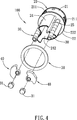
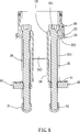
Für ein bevorzugtes Ausführungsbeispiel der erfindungsgemäßen Befestigungsanordnung für einen Wasserhahn wird auf
Beim Wasserhahn
Der Wasserhahn
Wie in
Wie in
In diesem Ausführungsbeispiel können an der Außenwandfläche der Umfangswand
Zu bemerken ist, dass mittels des Arretierelements
Die Positioniergewindestangen
Die Klemmstücke
An der oberen Wandfläche der Klemmstücke
Am unteren Ende der jeweiligen Positioniergewindestangen
Die Befestigungsanordnung für einen Wasserhahn gemäß diesem Ausführungsbeispiel umfasst ferner eine Unterlegscheibe
Erfindungsgemäß ist die Begrenzungswand
Die Begrenzungssperrstange
Die erfindungsgemäße Begrenzungssperrstange
ZITATE ENTHALTEN IN DER BESCHREIBUNG QUOTES INCLUDE IN THE DESCRIPTION
Diese Liste der vom Anmelder aufgeführten Dokumente wurde automatisiert erzeugt und ist ausschließlich zur besseren Information des Lesers aufgenommen. Die Liste ist nicht Bestandteil der deutschen Patent- bzw. Gebrauchsmusteranmeldung. Das DPMA übernimmt keinerlei Haftung für etwaige Fehler oder Auslassungen.This list of the documents listed by the applicant has been generated automatically and is included solely for the better information of the reader. The list is not part of the German patent or utility model application. The DPMA assumes no liability for any errors or omissions.
Zitierte PatentliteraturCited patent literature
- US 7748406 [0003] US 7748406 [0003]
- US 6757921 [0004] US 6757921 [0004]
- US 4848395 [0008] US 4848395 [0008]
Claims (7)
Applications Claiming Priority (2)
| Application Number | Priority Date | Filing Date | Title |
|---|---|---|---|
| CN201220475180.5 | 2012-09-17 | ||
| CN2012204751805U CN202913467U (en) | 2012-09-17 | 2012-09-17 | Fixing structure of faucet |
Publications (1)
| Publication Number | Publication Date |
|---|---|
| DE202013103517U1 true DE202013103517U1 (en) | 2013-08-22 |
Family
ID=48161789
Family Applications (1)
| Application Number | Title | Priority Date | Filing Date |
|---|---|---|---|
| DE201320103517 Expired - Lifetime DE202013103517U1 (en) | 2012-09-17 | 2013-08-05 | Fastening arrangement for a faucet |
Country Status (11)
| Country | Link |
|---|---|
| US (1) | US8763175B2 (en) |
| CN (1) | CN202913467U (en) |
| AT (1) | AT13849U1 (en) |
| BE (1) | BE1020831A5 (en) |
| CH (1) | CH706980B1 (en) |
| DE (1) | DE202013103517U1 (en) |
| ES (1) | ES1093106Y (en) |
| FR (1) | FR2995619B3 (en) |
| GB (1) | GB2506482B (en) |
| NL (1) | NL2011243B1 (en) |
| PL (1) | PL68165Y1 (en) |
Cited By (3)
| Publication number | Priority date | Publication date | Assignee | Title |
|---|---|---|---|---|
| EP3045592A1 (en) * | 2015-01-15 | 2016-07-20 | Eisl Sanitär GmbH | Fitting with separate assembly unit |
| EP3048206A1 (en) * | 2015-01-22 | 2016-07-27 | Globe Union Industrial Corp. | Faucet installing assembly |
| ITUB20153967A1 (en) * | 2015-09-14 | 2017-03-14 | Vincenzo Magistro | TAP WITH UPPER INSTALLATION |
Families Citing this family (33)
| Publication number | Priority date | Publication date | Assignee | Title |
|---|---|---|---|---|
| GB2486659B (en) * | 2010-12-21 | 2018-10-31 | Norcros Group Holdings Ltd | Fluid flow control device |
| EP2753853B1 (en) * | 2011-09-09 | 2020-08-26 | CeramTec GmbH | Single lever mixer tap for a wash basin |
| CN202629230U (en) * | 2012-01-18 | 2012-12-26 | 深圳成霖洁具股份有限公司 | Pull-out faucet fixing structure |
| GB2522872B (en) * | 2014-02-06 | 2016-08-03 | Ppi Xiamen Ind Co Ltd | Quick assembly mechanism for faucet |
| JP1524047S (en) | 2014-07-15 | 2015-05-25 | ||
| US20160024762A1 (en) * | 2014-07-22 | 2016-01-28 | Globe Union Industrial Corp. | Lavatory faucet |
| WO2016073978A1 (en) | 2014-11-07 | 2016-05-12 | Holley Performance Products, Inc. | Liquid reservoir system and method |
| US10364556B2 (en) * | 2015-06-06 | 2019-07-30 | Hunter Innovations, Llc | Tension-based mechanical coupling device |
| US9796259B2 (en) * | 2015-12-14 | 2017-10-24 | Holley Performance Products, Inc. | Systems and methods for installing and sealing fuel pump in fuel tank |
| DE202016000472U1 (en) * | 2016-01-27 | 2017-04-28 | Neoperl Gmbh | Sanitary spout, sanitary fitting and use of a spout |
| KR20180090880A (en) * | 2016-05-30 | 2018-08-13 | 플로우테크 키친 앤 배쓰룸 테크놀로지 컴퍼니 리미티드 | Upper mounting device |
| CN107975106B (en) * | 2016-10-21 | 2024-02-06 | 厦门松霖科技股份有限公司 | Bench quick-mounting and quick-dismounting device for faucet |
| US10006190B1 (en) * | 2016-12-02 | 2018-06-26 | Moen Incorporated | Pullout faucet with mounting system |
| CN206815452U (en) * | 2017-05-15 | 2017-12-29 | 厦门方特卫浴有限公司 | A kind of Fast Installation structure of weight |
| CN107190814B (en) * | 2017-06-30 | 2022-11-15 | 九牧厨卫股份有限公司 | Hovering positioning device and related pull-out faucet |
| CN107288182A (en) * | 2017-07-28 | 2017-10-24 | 厦门英仕卫浴有限公司 | Mounting structure in a kind of faucet platform |
| US10030370B1 (en) * | 2017-09-15 | 2018-07-24 | Globe Union Industries Corp. | Top mounting faucet assembly |
| US10450729B2 (en) * | 2017-09-20 | 2019-10-22 | Globe Union Industrial Corp. | Pull-out faucet |
| CN107470045A (en) * | 2017-09-21 | 2017-12-15 | 开平市明福卫浴实业有限公司 | It is a kind of can accurate temperature controlling gondola water faucet |
| US20190119888A1 (en) * | 2017-10-24 | 2019-04-25 | Ncip Inc. | Water faucet |
| US11300217B2 (en) | 2018-09-10 | 2022-04-12 | Kohler Co. | Faucet with improved valve |
| CN109267616A (en) * | 2018-11-19 | 2019-01-25 | 蒋飞龙 | A kind of Fast Installation structure of tap |
| CN110043704B (en) * | 2019-04-08 | 2024-08-16 | 百路达(厦门)工业有限公司 | Delay tap |
| US10934692B2 (en) | 2019-04-15 | 2021-03-02 | Prier Products, Inc. | Hydrant mounting bracket |
| CN109864641A (en) * | 2019-04-15 | 2019-06-11 | 侯文玲 | A kind of paediatrics nursing bath cleaning device |
| CN110454600B (en) * | 2019-09-12 | 2025-02-11 | 鹏威(厦门)工业有限公司 | Valve core seat fixing structure of pull-out faucet and pull-out faucet |
| DE102020108555A1 (en) * | 2020-03-27 | 2021-09-30 | Grohe Ag | Outlet element for a drinking water dispenser |
| CN113187034B (en) * | 2021-06-01 | 2025-04-25 | 温州亿胜洁具有限公司 | An expansion type faucet fixing seat |
| CN113520768B (en) * | 2021-08-18 | 2023-01-13 | 中国人民解放军陆军军医大学第一附属医院 | Portable dressing change auxiliary mechanism |
| CN114753452A (en) * | 2022-04-21 | 2022-07-15 | 广州海鸥住宅工业股份有限公司 | Faucet countertop quick disassembly structure and faucet countertop |
| EP4316986B1 (en) * | 2022-08-03 | 2026-02-25 | Zodiac Cabin Controls GmbH | Bracket |
| KR102595427B1 (en) * | 2023-02-22 | 2023-10-31 | 트랜드 주식회사 | Sink faucet |
| IT202300027078A1 (en) * | 2023-12-19 | 2025-06-19 | Alfredo Albanelli | DEVICE FOR FIXING A TAP |
Citations (3)
| Publication number | Priority date | Publication date | Assignee | Title |
|---|---|---|---|---|
| US4848395A (en) | 1987-05-23 | 1989-07-18 | Friedrich Grohe Armaturenfabrik Gmbh & Co. | Mixing faucet |
| US6757921B2 (en) | 2002-07-16 | 2004-07-06 | Kohler Co. | Pull-out faucet |
| US7748406B2 (en) | 2005-04-01 | 2010-07-06 | Newfrey Llc | Two handle pull-out faucet |
Family Cites Families (13)
| Publication number | Priority date | Publication date | Assignee | Title |
|---|---|---|---|---|
| US5388287A (en) * | 1993-07-12 | 1995-02-14 | Ecowater Systems, Inc. | Countertop faucet assembly |
| US5515882A (en) * | 1995-06-22 | 1996-05-14 | Hennis; Ronald H. | Apparatus for installation of a fixture on a surface |
| JP3153782B2 (en) * | 1997-03-19 | 2001-04-09 | 株式会社イナックス | Article mounting structure |
| JPH10274217A (en) * | 1997-03-28 | 1998-10-13 | Inax Corp | Annular member fixing structure |
| US6334226B1 (en) * | 1997-10-22 | 2002-01-01 | Toto Ltd. | Faucet support member |
| JP2002250061A (en) * | 2001-02-27 | 2002-09-06 | Mym Corp | Faucet mounting device |
| US6792629B2 (en) * | 2003-01-28 | 2004-09-21 | Masco Corporation Of Indiana | System and technique for mounting a faucet |
| US7698755B2 (en) * | 2005-08-29 | 2010-04-20 | Masco Corporation Of Indiana | Overhead cam faucet mounting system |
| US20090276954A1 (en) * | 2008-05-08 | 2009-11-12 | Kyle Robert Davidson | Spout mounting |
| FI121756B (en) * | 2009-05-15 | 2011-03-31 | Grana Finland Ab Oy | Method and apparatus for attaching a crane to a base support |
| US8256463B2 (en) * | 2010-01-29 | 2012-09-04 | Newfrey Llc | Faucet with adjustable height spout |
| US8528129B2 (en) * | 2010-12-01 | 2013-09-10 | Globe Union Industrial Corp. | Fixing structure of a faucet and an operating method thereof |
| CN202629230U (en) * | 2012-01-18 | 2012-12-26 | 深圳成霖洁具股份有限公司 | Pull-out faucet fixing structure |
-
2012
- 2012-09-17 CN CN2012204751805U patent/CN202913467U/en not_active Expired - Lifetime
-
2013
- 2013-07-21 GB GB201313081A patent/GB2506482B/en not_active Expired - Fee Related
- 2013-07-31 NL NL2011243A patent/NL2011243B1/en not_active IP Right Cessation
- 2013-07-31 ES ES201330953U patent/ES1093106Y/en not_active Expired - Fee Related
- 2013-08-05 DE DE201320103517 patent/DE202013103517U1/en not_active Expired - Lifetime
- 2013-08-06 US US13/959,992 patent/US8763175B2/en active Active
- 2013-08-08 FR FR1357871A patent/FR2995619B3/en not_active Expired - Lifetime
- 2013-08-08 CH CH01365/13A patent/CH706980B1/en active IP Right Maintenance
- 2013-09-02 AT ATGM279/2013U patent/AT13849U1/en not_active IP Right Cessation
- 2013-09-06 PL PL122335U patent/PL68165Y1/en unknown
- 2013-09-12 BE BE201300601A patent/BE1020831A5/fr not_active IP Right Cessation
Patent Citations (3)
| Publication number | Priority date | Publication date | Assignee | Title |
|---|---|---|---|---|
| US4848395A (en) | 1987-05-23 | 1989-07-18 | Friedrich Grohe Armaturenfabrik Gmbh & Co. | Mixing faucet |
| US6757921B2 (en) | 2002-07-16 | 2004-07-06 | Kohler Co. | Pull-out faucet |
| US7748406B2 (en) | 2005-04-01 | 2010-07-06 | Newfrey Llc | Two handle pull-out faucet |
Cited By (3)
| Publication number | Priority date | Publication date | Assignee | Title |
|---|---|---|---|---|
| EP3045592A1 (en) * | 2015-01-15 | 2016-07-20 | Eisl Sanitär GmbH | Fitting with separate assembly unit |
| EP3048206A1 (en) * | 2015-01-22 | 2016-07-27 | Globe Union Industrial Corp. | Faucet installing assembly |
| ITUB20153967A1 (en) * | 2015-09-14 | 2017-03-14 | Vincenzo Magistro | TAP WITH UPPER INSTALLATION |
Also Published As
| Publication number | Publication date |
|---|---|
| CH706980A2 (en) | 2014-03-31 |
| GB201313081D0 (en) | 2013-09-04 |
| ES1093106Y (en) | 2014-02-05 |
| GB2506482B (en) | 2014-11-26 |
| FR2995619A3 (en) | 2014-03-21 |
| ES1093106U (en) | 2013-11-15 |
| CH706980B1 (en) | 2017-09-29 |
| AT13849U1 (en) | 2014-10-15 |
| US8763175B2 (en) | 2014-07-01 |
| US20140075667A1 (en) | 2014-03-20 |
| CN202913467U (en) | 2013-05-01 |
| NL2011243B1 (en) | 2015-10-19 |
| FR2995619B3 (en) | 2015-02-13 |
| NL2011243A (en) | 2014-03-18 |
| BE1020831A5 (en) | 2014-05-06 |
| PL122335U1 (en) | 2014-03-31 |
| PL68165Y1 (en) | 2016-01-29 |
| GB2506482A (en) | 2014-04-02 |
Similar Documents
| Publication | Publication Date | Title |
|---|---|---|
| DE202013103517U1 (en) | Fastening arrangement for a faucet | |
| DE202012104488U1 (en) | Fastening arrangement for a pull-out tap | |
| EP2101002B1 (en) | Built in box with variable mounting of sanitary fittings | |
| DE102004040084B4 (en) | Sanitary concealed fitting | |
| DE4201203A1 (en) | TAP SPOUT | |
| DE2444245A1 (en) | HOSE COUPLING | |
| DE2732440A1 (en) | COUPLING WITH AUTOMATIC SHUT-OFF VALVE FOR PIPES, IN PARTICULAR HOSE PIPES | |
| DE2311840C2 (en) | Mixing valve for two fluid flows | |
| DE102007043309A1 (en) | Sanitary fitting i.e. one handle-mixing faucet, has two detachable retaining units provided in insert, and water inlet pipes with protection devices which are supported at detachable retaining units | |
| DE102007009409B4 (en) | Fitting with swivel spout | |
| DE102009040191B4 (en) | Fixing device for a sanitary fitting | |
| DE102010006375B4 (en) | plumbing fixture | |
| DE202021104030U1 (en) | Fixing device for taps | |
| EP3988724A1 (en) | Inlet device, tub body and method | |
| DE102013112005A1 (en) | Fastener for a wall-hung object | |
| DE202014102006U1 (en) | plumbing fixture | |
| EP0804970B1 (en) | Hand held spray gun for high pressure cleaning apparatus | |
| EP2853643B1 (en) | Connecting body system for a concealed mounted sanitary fixture | |
| DE102014109806A1 (en) | Water outlet fitting for a washbasin or a sink | |
| EP1161600A1 (en) | Sanitary appliance and installation method | |
| DE19545945C1 (en) | Water tap with removable tap body | |
| DE4204344C3 (en) | Water meter mounting and installation device | |
| DE102008042231A1 (en) | Pipe connection device for water supply line, comprises pipe connection piece, which is provided with chamber, and slide bush is provided, which is arranged in receiving part of pipe connection piece | |
| EP1956151A2 (en) | Sanitary fitting | |
| DE4431869A1 (en) | Tap fastener for sinks, worktops, etc. |
Legal Events
| Date | Code | Title | Description |
|---|---|---|---|
| R207 | Utility model specification |
Effective date: 20131017 |
|
| R082 | Change of representative |
Representative=s name: LANGPATENT ANWALTSKANZLEI IP LAW FIRM, DE |
|
| R150 | Utility model maintained after payment of first maintenance fee after three years | ||
| R151 | Utility model maintained after payment of second maintenance fee after six years | ||
| R152 | Utility model maintained after payment of third maintenance fee after eight years | ||
| R071 | Expiry of right |