DE202013011662U1 - Storage type device for plant irrigation (embodiments) - Google Patents

Storage type device for plant irrigation (embodiments) Download PDF

Info

Publication number
DE202013011662U1
DE202013011662U1 DE202013011662.5U DE202013011662U DE202013011662U1 DE 202013011662 U1 DE202013011662 U1 DE 202013011662U1 DE 202013011662 U DE202013011662 U DE 202013011662U DE 202013011662 U1 DE202013011662 U1 DE 202013011662U1
Authority
DE
Germany
Prior art keywords
tank
storage type
type apparatus
plant
plant watering
Prior art date
Legal status (The legal status is an assumption and is not a legal conclusion. Google has not performed a legal analysis and makes no representation as to the accuracy of the status listed.)
Expired - Lifetime
Application number
DE202013011662.5U
Other languages
German (de)
Current Assignee (The listed assignees may be inaccurate. Google has not performed a legal analysis and makes no representation or warranty as to the accuracy of the list.)
Individual
Original Assignee
Individual
Priority date (The priority date is an assumption and is not a legal conclusion. Google has not performed a legal analysis and makes no representation as to the accuracy of the date listed.)
Filing date
Publication date
Application filed by Individual filed Critical Individual
Publication of DE202013011662U1 publication Critical patent/DE202013011662U1/en
Anticipated expiration legal-status Critical
Expired - Lifetime legal-status Critical Current

Links

Images

Classifications

    • AHUMAN NECESSITIES
    • A01AGRICULTURE; FORESTRY; ANIMAL HUSBANDRY; HUNTING; TRAPPING; FISHING
    • A01GHORTICULTURE; CULTIVATION OF VEGETABLES, FLOWERS, RICE, FRUIT, VINES, HOPS OR SEAWEED; FORESTRY; WATERING
    • A01G27/00Self-acting watering devices, e.g. for flower-pots
    • A01G27/04Self-acting watering devices, e.g. for flower-pots using wicks or the like
    • A01G27/06Self-acting watering devices, e.g. for flower-pots using wicks or the like having a water reservoir, the main part thereof being located wholly around or directly beside the growth substrate

Landscapes

  • Engineering & Computer Science (AREA)
  • Water Supply & Treatment (AREA)
  • Life Sciences & Earth Sciences (AREA)
  • Environmental Sciences (AREA)
  • Cultivation Receptacles Or Flower-Pots, Or Pots For Seedlings (AREA)

Abstract

Speichertypgerät für eine Pflanzenbewässerung, das einen unteren Tank und einen oberen Tank umfasst, dadurch gekennzeichnet, dass der untere Tank Seitenwände und einen Boden umfasst, der obere Tank Seitenwände und einen Boden umfasst und mit der der Oberseite nach unten in dem unteren Tank angeordnet ist, wodurch ein Spalt zwischen den Seitenwänden des oberen und unteren Tanks gebildet wird, der ausreicht, um die Flüssigkeit aus dem unteren Tank herauf zu dem Boden zu liefern, wobei ein rohrförmiges Element in den Boden des oberen Tanks zum Zuführen der Flüssigkeit in den oberen Tank montiert ist.Plant irrigation type storage device comprising a lower tank and an upper tank, characterized in that the lower tank has side walls and a bottom, the upper tank has side walls and a bottom, and is arranged upside down in the lower tank, thereby forming a gap between the side walls of the upper and lower tanks sufficient to supply the liquid from the lower tank to the bottom, with a tubular member mounted in the bottom of the upper tank for supplying the liquid to the upper tank is.

Description

Das Gebrauchsmuster betrifft Landwirtschaft, nämlich Speichertypgeräte für eine Pflanzenbewässerung und kann für eine Aufzucht von Pflanzen verwendet werden, insbesondere Blumen, Beeren, Setzlingen und Zierpflanzen in Gewächshäusern, im Innenraum oder an Freiluft.The utility model relates to agriculture, namely storage type devices for plant irrigation and may be used for rearing plants, in particular flowers, berries, seedlings and ornamental plants in greenhouses, indoors or outdoors.

Speichertypgeräte für eine gesteuerte Pflanzenbewässerung sind bekannt, die einen unteren und einen oberen Tank umfassen (siehe beispielsweise die Erfindungsbeschreibung von US 7000351 , IPC A01G 25/00 (2006.01), veröffentlicht am 21.02.2006; die Erfindungsbeschreibung von FR 2766327 (A1) , IPC A01G 27/06, veröffentlicht am 29.01.1999; die Gebrauchsmusterbeschreibung von RU 32658 , IPC A01G 9/02, veröffentlicht am 09.27.2003).Storage type devices for controlled plant irrigation are known which comprise a lower and an upper tank (see for example the description of the invention of US 7000351 , IPC A01G 25/00 (2006.01), published on 21.02.2006; the invention description of FR 2766327 (A1) , IPC A01G 27/06, published on 29.01.1999; the utility model description of RU 32658 , IPC A01G 9/02, published on 09.27.2003).

Der Hauptnachteil der obigen Geräte ist die geringe Effizienz einer Flüssigkeitsversorgung, wobei die Flüssigkeit für eine Pflanzenbewässerung erforderlich ist.The main disadvantage of the above devices is the low efficiency of a liquid supply, which liquid is required for plant irrigation.

Der nächstgelegene Prototyp der beanspruchten technischen Lösung ist ein Speichertypgerät für eine Pflanzenbewässerung, das einen unteren Tank und einen oberen Tank umfasst (siehe beispielsweise die Erfindungsbeschreibung von FR 2766327 (A1) , IPC A01G 27/06, veröffentlicht am 29.01.1999).The closest prototype of the claimed technical solution is a storage type plant irrigation device comprising a lower tank and an upper tank (see, for example, the invention description of FR 2766327 (A1) , IPC A01G 27/06, published on 29.01.1999).

Der Nachteil des nächstgelegenen Prototyps ist die geringe Effizienz einer Flüssigkeitsversorgung, die für eine Pflanzenbewässerung erforderlich ist, insbesondere wenn dieser in dem Boden unter den Pflanzenwurzeln vergraben ist.The disadvantage of the nearest prototype is the low efficiency of a liquid supply required for plant irrigation, especially when buried in the soil below the plant roots.

Das technische Ergebnis ist es, die Effizienz einer Flüssigkeitszufuhr zu erhöhen, um eine optimale Pflanzenbewässerung bereitzustellen.The technical result is to increase the efficiency of fluid intake to provide optimal plant irrigation.

Der Gegenstand der beanspruchten technischen Lösung gemäß der ersten Ausführungsform ist dadurch gekennzeichnet, dass dieser einen unteren Tank und einen oberen Tank umfasst, wobei der untere Tank Seitenwände und einen Boden umfasst, der obere Tank Seitenwände und einen Boden umfasst und mit der Oberseite nach unten in dem unteren Tank angeordnet ist, wodurch ein Spalt zwischen den Seitenwänden des oberen und unteren Tanks gebildet wird, der ausreicht, um die Flüssigkeit aus dem unteren Tank herauf zu dem Boden zu liefern, und ein rohrförmiges Element in den oberen Tankboden zum Zuführen der Flüssigkeit in den oberen Tank montiert ist.The subject matter of the claimed technical solution according to the first embodiment is characterized in that it comprises a lower tank and an upper tank, the lower tank comprising side walls and a bottom, the upper tank including side walls and a bottom and having the top downwards the lower tank is formed, whereby a gap between the side walls of the upper and lower tanks is formed, which is sufficient to deliver the liquid from the lower tank up to the bottom, and a tubular member in the upper tank bottom for supplying the liquid in the upper tank is mounted.

Der Gegenstand der beanspruchten technischen Lösung nach der zweiten Ausführungsform ist dadurch gekennzeichnet, dass dieser mit einem Deckel, der auf einen Tank montiert ist, mit einer oder mehreren Öffnungen und einem rohrförmiges Element zum Zuführen der Flüssigkeit bereitgestellt ist, bei dem das rohrförmige Element mit einer der Öffnungen verbunden ist.The subject matter of the claimed technical solution according to the second embodiment is characterized in that it is provided with a lid mounted on a tank with one or more openings and a tubular element for supplying the liquid, in which the tubular element is provided with a liquid the openings is connected.

Der Gegenstand der technischen Lösung wird mittels der Zeichnungen offenbart, die mögliche Ausführungsformen spezifizieren.The subject matter of the technical solution is disclosed by means of the drawings which specify possible embodiments.

1 ist eine Schnittseitenansicht gemäß der ersten Ausführungsform; 1 is a sectional side view according to the first embodiment;

2 ist eine Schnittseitenansicht gemäß der ersten Ausführungsform einer Lösung, die ein wasserdurchlässiges Element umfasst; 2 Fig. 10 is a sectional side view according to the first embodiment of a solution comprising a water-permeable member;

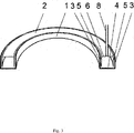
3 ist eine axonometrische Schnittansicht gemäß der ersten Ausführungsform einer Lösung, die einen bogenförmigen Tank mit geschlossenem Raum umfasst; 3 Fig. 10 is an axonometric sectional view according to the first embodiment of a solution comprising an arcuate tank with a closed space;

4 eine axonometrische Ansicht gemäß der ersten Ausführungsform einer Lösung, die einen oberen und unteren Tank mit gekrümmten Raum umfasst; 4 an axonometric view according to the first embodiment of a solution comprising an upper and lower tank with curved space;

5 ist eine Schnittansicht entlang einer Linie A-A gemäß der ersten Ausführungsform einer Lösung, die einen oberen und unteren Tank mit gekrümmtem Raum umfasst; 5 Fig. 10 is a sectional view taken along a line AA according to the first embodiment of a solution including a curved-space upper and lower tanks;

6 ist eine axonometrische Ansicht gemäß der ersten Ausführungsform einer Lösung, die einen Tank mit geschlossenem Raum umfasst, der eine rechteckige Form in horizontaler Ebene aufweist; 6 is an axonometric view according to the first embodiment of a solution comprising a closed space tank having a rectangular shape in a horizontal plane;

7 ist eine Schnittansicht entlang der Linie A-A gemäß der ersten Ausführungsform einer Lösung, die einen Tank mit geschlossenem Raum umfasst, der eine rechteckige Form in horizontaler Ebene aufweist; 7 is a sectional view taken along the line AA according to the first embodiment of a solution comprising a tank with a closed space having a rectangular shape in the horizontal plane;

8 ist eine Schnittseitenansicht gemäß der ersten Ausführungsform einer Lösung, die ein Seil umfasst, das aus einem wasserdurchlässigen Material hergestellt ist; 8th Fig. 3 is a sectional side view according to the first embodiment of a solution comprising a rope made of a water-permeable material;

9 ist eine Schnittseitenansicht gemäß der ersten Ausführungsform, die einen Schwimmer und einen Stift umfasst; 9 Fig. 3 is a sectional side view according to the first embodiment, which includes a float and a pin;

10 ist eine Schnittseitenansicht gemäß der ersten Ausführungsform, die ein wasserdurchlässiges Element, einen Schwimmer und einen Stift umfasst; 10 Fig. 10 is a sectional side view according to the first embodiment, which includes a water-permeable member, a float and a pin;

11 ist eine Schnittseitenansicht gemäß der ersten Ausführungsform, die ein Seil, das aus einem wasserdurchlässigen Material hergestellt ist, einen Schwimmer und einen Stift umfasst; 11 is a sectional side view according to the first embodiment, a rope that made a water-permeable material, comprising a float and a pin;

12 ist eine Schnittseitenansicht gemäß der zweiten Ausführungsform mit einem Deckel; 12 is a sectional side view according to the second embodiment with a lid;

13 ist eine Schnittseitenansicht gemäß der zweiten Ausführungsform, die einen Schwimmer und einen Stift umfasst; 13 Fig. 10 is a sectional side view according to the second embodiment, which includes a float and a pin;

14 ist eine Schnittseitenansicht gemäß der zweiten Ausführungsform, die einen Deckel und Seitenelemente umfasst; 14 Fig. 10 is a sectional side view according to the second embodiment, which includes a lid and side members;

15 ist eine Schnittseitenansicht gemäß der zweiten Ausführungsform, die einen Deckel, Seitenelemente, einen Schwimmer und einen Stift umfasst. 15 Fig. 10 is a sectional side view according to the second embodiment, which includes a lid, side members, a float and a pin.

Ein Speichertypgerät für eine Pflanzenbewässerung gemäß der ersten Ausführungsform umfasst einen unteren Tank 1 und einen oberen Tank 2. Der untere Tank 1 umfasst Seitenwände 3 und einen Boden 4 und der obere Tank 2 umfasst Seitenwände 5 und einen Boden 6 und ist mit der Oberseite nach unten in den unteren Tank 1 mit dem Boden 6 an der Oberseite angeordnet, wodurch ein Spalt zwischen den Seitenwänden 3, 5 des oberen und unteren Tanks 1, 2 gebildet wird. Der Spalt ist ausreichend, um die Flüssigkeit aus dem unteren Tank 1 herauf zu dem Boden 7 zu liefern. Ein rohrförmiges Element 8 ist in den Boden des oberen Tanks 2 zum Zuführen der Flüssigkeit in den oberen Tank 2 montiert (1, 2, 3, 4, 5, 6, 7, 8, 9).A storage type apparatus for plant irrigation according to the first embodiment includes a lower tank 1 and an upper tank 2 , The lower tank 1 includes side walls 3 and a floor 4 and the upper tank 2 includes side walls 5 and a floor 6 and is upside down in the bottom tank 1 with the ground 6 arranged at the top, creating a gap between the side walls 3 . 5 of the upper and lower tanks 1 . 2 is formed. The gap is sufficient to remove the liquid from the lower tank 1 up to the ground 7 to deliver. A tubular element 8th is in the bottom of the upper tank 2 for feeding the liquid into the upper tank 2 assembled ( 1 . 2 . 3 . 4 . 5 . 6 . 7 . 8th . 9 ).

Ein wasserdurchlässiges Element 9 kann in dem Spalt zwischen den Seitenwänden 5 des oberen Tanks 2 und den Seitenwänden 3 des unteren Tanks 1 angeordnet sein, wobei das Element 9 mit Durchlässigkeitseigenschaften gemäß einer bestimmten Pflanzenart aufweist, an die ein Speichertypgerät für eine Pflanzenbewässerung angrenzt, und deren Wasserverbrauch (2).A water-permeable element 9 can be in the gap between the side walls 5 of the upper tank 2 and the side walls 3 of the lower tank 1 be arranged, wherein the element 9 having permeability characteristics in accordance with a particular plant species to which a storage-type plant irrigation device adjoins, and their water consumption ( 2 ).

In einem anderen Fall können der untere und der obere Tank 1, 2 in einer Zylinderform bereitgestellt sein.In another case, the lower and the upper tank can 1 . 2 be provided in a cylindrical shape.

Der untere und der obere Tank 1, 2 können länglich oder sowohl länglich als auch gekrümmt sein (4, 5).The lower and the upper tank 1 . 2 may be oblong or both oblong and curved ( 4 . 5 ).

Der untere und der obere Tank 1, 2 können bereitgestellt sein, einen geschlossenen Raum ringförmiger Form zu bilden, wobei der Querschnitt seiner Seitenwände ein Oval oder einen Kreis oder ein Teil von diesen erzeugt (3).The lower and the upper tank 1 . 2 may be provided to form a closed space of annular shape, the cross-section of its side walls forming an oval or a circle or part thereof ( 3 ).

Der untere und obere Tank 1, 2 können in einem polygonalen Querschnitt bereitgestellt sein, der insbesondere, dreieckig oder quadratisch oder rechteckig oder fünfeckig oder sechseckig oder achteckig oder sternförmig ist.The lower and upper tank 1 . 2 may be provided in a polygonal cross-section which is in particular, triangular or square or rectangular or pentagonal or hexagonal or octagonal or star-shaped.

In Abhängigkeit der Aufgaben einer Pflanzungsgestaltung können der untere und obere Tank 1, 2 bereitgestellt sein, eine geschlossene Raumform zu bilden, wobei der Querschnitt seiner Seitenwanderzeugenden entweder ein Quadrat oder ein Rechteck oder ein Polygon ist (6, 7).Depending on the tasks of a planting design, the lower and upper tank can 1 . 2 be provided to form a closed spatial form, wherein the cross-section of its Seitenwanderzeugenden is either a square or a rectangle or a polygon ( 6 . 7 ).

Der Boden des oberen Tanks 2 kann mit einer oder mehreren Öffnungen bereitgestellt sein, in denen ein Seil 14 eingesetzt ist, das aus einem wasserdurchlässigen Material hergestellt ist, wobei ein oder beide Enden des Seils 14 innerhalb des oberen Tanks 2 angeordnet sind, und ein Teil des Seils 14 sich an der Außenseite des Bodens 6 des oberen Tanks 2 befindet (8).The bottom of the upper tank 2 can be provided with one or more openings in which a rope 14 inserted, which is made of a water-permeable material, wherein one or both ends of the rope 14 inside the upper tank 2 are arranged, and part of the rope 14 on the outside of the floor 6 of the upper tank 2 located ( 8th ).

Der Boden 2 des oberen Tanks kann einen Schwimmer 10 umfassen, der mit einem daran befestigten Stift 11 bereitgestellt ist, bei dem ein Teil von diesem in einem rohrförmigen Element 8 angeordnet ist, und das obere Ende des Stiftes 11 über das obere Ende des rohrförmigen Elements 8 hinausragt (9, 10, 11).The floor 2 the upper tank can be a float 10 include, with a pin attached to it 11 is provided, in which a part of this in a tubular element 8th is arranged, and the upper end of the pin 11 over the upper end of the tubular element 8th protrudes ( 9 . 10 . 11 ).

Ein Speichertypgerät für eine Pflanzenbewässerung gemäß der zweiten Ausführungsform umfasst einen Tank 15, der offen an der Oberseite mit einem Deckel 16 bereitgestellt ist, der auf den Tank 15 montiert ist und mit einer oder mehreren Öffnungen und einem rohrförmigen Element 17 für eine Flüssigkeitszuführung bereitgestellt ist, das an einer der Öffnungen befestigt ist (12).A storage type apparatus for plant irrigation according to the second embodiment includes a tank 15 which is open at the top with a lid 16 is provided on the tank 15 is mounted and with one or more openings and a tubular element 17 is provided for a liquid supply, which is attached to one of the openings ( 12 ).

Der Tank 15 eines einem Speichertypgerätes für eine Pflanzenbewässerung gemäß der zweiten Ausführungsform kann einen Schwimmer 18 umfassen, der mit einem daran befestigten Stift 19 bereitgestellt ist, dessen einer Teil in einem rohrförmigen Element 17 angeordnet ist, wobei das obere Ende des Stiftes 19 über das obere Ende des rohrförmigen Elements 17 hinausragt (13).The Tank 15 of a storage type apparatus for plant irrigation according to the second embodiment may include a float 18 include, with a pin attached to it 19 is provided, one part of which in a tubular element 17 is arranged, with the upper end of the pen 19 over the upper end of the tubular element 17 protrudes ( 13 ).

Ein Speichertypgerät für eine Pflanzenbewässerung gemäß der zweiten Ausführungsform kann einen Deckel 16 umfassen, der mit einer oder mehreren Öffnungen und Seitenelementen 20 bereitgestellt ist, die sich innerhalb des Tanks 15 nach unten erstrecken (14). Gemäß dieser Ausführungsform des beanspruchten Speichertypgerätes kann der Tank 15 ebenfalls einen Schwimmer 18 umfassen, der mit einem daran befestigten Stift 19 bereitgestellt ist, dessen einer Teil in einem rohrförmigen Element 17 angeordnet ist, wobei das obere Ende des Stiftes 19 über das obere Ende des rohrförmigen Elements 17 hinausragt (15).A storage type apparatus for plant irrigation according to the second embodiment may include a lid 16 include, with one or more openings and side elements 20 is deployed, which is inside the tank 15 extend downwards ( 14 ). According to this embodiment of the claimed storage type apparatus, the tank 15 also a swimmer 18 include, with a pin attached to it 19 is provided, one part of which in a tubular element 17 is arranged, with the upper end of the pin 19 over the upper end of the tubular element 17 protrudes ( 15 ).

Das Speichertypgerät für eine Pflanzenbewässerung gemäß der zweiten Ausführungsform kann mit den äußeren Formen verschiedener Modifikationen bereitgestellt sein, die ähnlich zu den äußeren Formen der oben genannten Modifikationen für das Speichertypgerät für eine Pflanzenbewässerung gemäß der ersten Ausführungsform sind. Der Tank 15 kann in einer Zylinderform, einer länglichen oder sowohl länglichen als auch gekrümmten Form, in einem polygonalen insbesondere dreieckigen oder quadratischen oder rechteckigen oder fünfeckigen oder sechseckigen oder achteckigen oder sternförmigen Querschnitt bereitgestellt sein. Weiter kann dieser bereitgestellt sein, einen geschlossenen Raum ringförmiger Form zu bilden, wobei der Querschnitt seiner Seitenwanderzeugenden ein Oval oder einen Kreis oder einen Teil davon ist. Der Tank 15 kann ebenfalls bereitgestellt sein, eine geschlossene Raumform zu bilden, wobei der Querschnitt seiner Seitenwanderzeugenden ein Quadrat oder ein Rechteck oder ein Polygon ist. Gemäß den Modifikationen des Tanks 15, wie oben beschrieben oder ähnlich zu dem beanspruchten Speichertypgerät für eine Pflanzenbewässerung ist der Deckel 16 mit einer oder mehreren Öffnungen mit einer Form bereitgestellt, die komplementär zu der Form des Tanks 15 ist. Falls erforderlich, kann der Deckel 16 aus getrennten Teilen zusammengesetzt sein, die fest miteinander zusammengepasst sind.The plant irrigation storage type apparatus according to the second embodiment may be provided with the outer shapes of various modifications similar to the external forms of the above modifications for the plant irrigation storage type apparatus according to the first embodiment. The Tank 15 may be provided in a cylindrical shape, an oblong or both elongated and curved shape, in a polygonal, in particular triangular or square or rectangular or pentagonal or hexagonal or octagonal or star-shaped cross-section. Further, it may be provided to form a closed space of annular shape, the cross section of its side wall ends being an oval or a circle or a part thereof. The Tank 15 may also be provided to form a closed spatial form, wherein the cross-section of its Seitenwanderzeugenden is a square or a rectangle or a polygon. According to the modifications of the tank 15 As described above or similar to the claimed storage type apparatus for plant irrigation is the lid 16 provided with one or more openings with a shape that is complementary to the shape of the tank 15 is. If necessary, the lid can 16 be composed of separate parts that are tightly fitted together.

Das Speichertypgerät für eine Pflanzenbewässerung wird wie folgt betrieben:
Das Speichertypgerät für eine Pflanzenbewässerung gemäß der ersten Ausführungsform wird vor einem Einpflanzen derart in den Boden 7 gesetzt, dass dieses anschließend unter den Pflanzenwurzeln oder nahe daran angeordnet ist. In diesem Fall sollte das obere Ende des rohrförmigen Elements 8 über der Oberfläche des Bodens 7 angeordnet werden. Eine derartige Anordnung verhindert, dass der Boden 7 in den oberen Tank 2 eindringt und stellt den oberen Tank 2 bereit, um mit einer Flüssigkeit gefüllt zu werden.
The storage type plant irrigation equipment is operated as follows:
The plant-type water storage type apparatus according to the first embodiment is so buried in the soil before planting 7 This is then placed below the plant roots or close to it. In this case, the upper end of the tubular element should be 8th above the surface of the soil 7 to be ordered. Such an arrangement prevents the ground 7 in the upper tank 2 penetrates and puts the upper tank 2 ready to be filled with a liquid.

Nach dem Pflanzen wird die Flüssigkeit durch das rohrförmige Element 8 in den oberen Tank 2 zugeführt. Die Flüssigkeitsmenge wird entweder durch den Flüssigkeitspegel in dem rohrförmigen Element 8, oder mittels des Schwimmers 10 mit einem daran befestigten Stift 11 gesteuert. Der Flüssigkeitspegel in dem oberen Tank 2 kann an dem oberen Ende des Stiftes 11 geschätzt werden, das über das obere Ende des rohrförmigen Elements 8 hinausragt. Die Flüssigkeit zwischen den Seitenwänden 3 des unteren Tanks 1 und den Seitenwänden 5 des oberen Tanks 2 wird dem Boden zugeführt. Wenn der Flüssigkeitspegel herabsinkt, wird die Flüssigkeit durch das rohrförmige Element 8 zu dem oberen Tank 2 hinzugefügt.After planting, the liquid passes through the tubular element 8th in the upper tank 2 fed. The amount of liquid is either due to the liquid level in the tubular element 8th , or by means of the float 10 with a pin attached to it 11 controlled. The liquid level in the upper tank 2 can be at the top of the pen 11 be appreciated that over the top of the tubular element 8th protrudes. The liquid between the side walls 3 of the lower tank 1 and the side walls 5 of the upper tank 2 is fed to the ground. As the liquid level drops, the liquid passes through the tubular member 8th to the upper tank 2 added.

Das Speichertypgerät für eine Pflanzenbewässerung gemäß der zweiten Ausführungsform wird in den Boden 7 vor einem Pflanzen derart angeordnet, dass dieses anschließend unter den Pflanzenwurzeln oder nahe daran angeordnet ist. In diesem Fall sollte das obere Ende des rohrförmigen Elements 17 oberhalb einer Oberfläche des Bodens 7 angeordnet sein. Eine derartige Anordnung verhindert, dass der Boden 7 in den Tank 15 eindringt und stellt den Tank 15 bereit, um mit Flüssigkeit gefüllt zu werden.The storage type apparatus for plant irrigation according to the second embodiment is placed in the ground 7 arranged in front of a plant such that it is subsequently arranged under the plant roots or close to it. In this case, the upper end of the tubular element should be 17 above a surface of the soil 7 be arranged. Such an arrangement prevents the ground 7 in the tank 15 penetrates and puts the tank 15 ready to be filled with liquid.

Nach einem Pflanzen wird die Flüssigkeit durch das rohrförmige Element 17 in den Tank 15 zugeführt. Die Flüssigkeitsmenge wird entweder durch den Flüssigkeitspegel in dem rohrförmigen Element 17 gesteuert oder mittels des Schwimmers 18, der mit dem daran befestigten Stift 19 bereitgestellt ist. Der Flüssigkeitspegel in dem Tank 15 kann an dem oberen Ende des Stifts 19 geschätzt werden, das über das obere Ende des rohrförmigen Elements 17 hinausragt. Durch die Öffnungen in dem Deckel 16 wird die Flüssigkeit aus dem Tank 15 zu dem Boden zugeführt. Wenn der Flüssigkeitspegel herabsinkt, wird die Flüssigkeit durch das rohrförmige Element 17 zu dem Tank 15 hinzugefügt.After planting, the liquid passes through the tubular element 17 in the tank 15 fed. The amount of liquid is either due to the liquid level in the tubular element 17 controlled or by means of the float 18 , with the pen attached to it 19 is provided. The liquid level in the tank 15 can be at the top of the pen 19 be appreciated that over the top of the tubular element 17 protrudes. Through the openings in the lid 16 the liquid gets out of the tank 15 fed to the ground. As the liquid level drops, the liquid passes through the tubular member 17 to the tank 15 added.

ZITATE ENTHALTEN IN DER BESCHREIBUNG QUOTES INCLUDE IN THE DESCRIPTION

Diese Liste der vom Anmelder aufgeführten Dokumente wurde automatisiert erzeugt und ist ausschließlich zur besseren Information des Lesers aufgenommen. Die Liste ist nicht Bestandteil der deutschen Patent- bzw. Gebrauchsmusteranmeldung. Das DPMA übernimmt keinerlei Haftung für etwaige Fehler oder Auslassungen.This list of the documents listed by the applicant has been generated automatically and is included solely for the better information of the reader. The list is not part of the German patent or utility model application. The DPMA assumes no liability for any errors or omissions.

Zitierte PatentliteraturCited patent literature

  • US 7000351 [0002] US 7000351 [0002]
  • FR 2766327 A1 [0002, 0004] FR 2766327 A1 [0002, 0004]
  • RU 32658 U [0002] RU 32658 U [0002]

Claims (12)

Speichertypgerät für eine Pflanzenbewässerung, das einen unteren Tank und einen oberen Tank umfasst, dadurch gekennzeichnet, dass der untere Tank Seitenwände und einen Boden umfasst, der obere Tank Seitenwände und einen Boden umfasst und mit der der Oberseite nach unten in dem unteren Tank angeordnet ist, wodurch ein Spalt zwischen den Seitenwänden des oberen und unteren Tanks gebildet wird, der ausreicht, um die Flüssigkeit aus dem unteren Tank herauf zu dem Boden zu liefern, wobei ein rohrförmiges Element in den Boden des oberen Tanks zum Zuführen der Flüssigkeit in den oberen Tank montiert ist.A plant watering storage type apparatus comprising a lower tank and an upper tank, characterized in that the lower tank includes side walls and a bottom, the upper tank has side walls and a bottom and is disposed upside down in the lower tank, whereby a gap is formed between the side walls of the upper and lower tanks sufficient to supply the liquid from the lower tank up to the bottom, a tubular member being mounted in the bottom of the upper tank for supplying the liquid into the upper tank is. Speichertypgerät für eine Pflanzenbewässerung nach Anspruch 1, dadurch gekennzeichnet, dass ein wasserdurchlässiges Element in dem Spalt zwischen den Seitenwänden des oberen und den Seitenwänden des unteren Tanks angeordnet ist.Plant watering storage type apparatus according to claim 1, characterized in that a water-permeable member is disposed in the gap between the side walls of the upper and side walls of the lower tank. Speichertypgerät für eine Pflanzenbewässerung nach einem der Ansprüche 1, 2, dadurch gekennzeichnet, dass der obere und untere Tank in einer Zylinderform bereitgestellt sind.Plant watering storage type apparatus according to any one of claims 1, 2, characterized in that the upper and lower tanks are provided in a cylindrical shape. Speichertypgerät für eine Pflanzenbewässerung nach einem der Ansprüche 1, 2, dadurch gekennzeichnet, dass der untere und obere Tank in einer länglichen oder sowohl länglichen als auch gekrümmten Form bereitgestellt sind.Plant watering storage type apparatus according to any one of claims 1, 2, characterized in that the lower and upper tanks are provided in an elongated or both elongated and curved shape. Speichertypgerät für eine Pflanzenbewässerung nach einem der Ansprüche 1, 2, dadurch gekennzeichnet, dass der untere und obere Tank in einem polygonalen Querschnitt bereitgestellt sind, der insbesondere dreieckig oder quadratisch oder rechteckig oder fünfeckig oder sechseckig oder achteckig oder sternförmig ist.Storage watering apparatus for plant irrigation according to any one of claims 1, 2, characterized in that the lower and upper tanks are provided in a polygonal cross-section which is in particular triangular or square or rectangular or pentagonal or hexagonal or octagonal or star-shaped. Speichertypgerät für eine Pflanzenbewässerung nach einem der Ansprüche 1, 2, dadurch gekennzeichnet, dass der untere und der obere Tanks bereitgestellt sind, einen geschlossenen Raum ringförmiger Form zu bilden, wobei der Querschnitt seiner Seitenwändeerzeugenden ein Oval oder einen Kreis oder ein Teil von diesen ist.A plant watering storage type apparatus according to any one of claims 1, 2, characterized in that the lower and upper tanks are provided to form a closed space of annular shape, the cross section of its side wall generators being an oval or a circle or part thereof. Speichertypgerät für eine Pflanzenbewässerung nach einem der Ansprüche 1, 2, dadurch gekennzeichnet, dass der untere und obere Tank bereitgestellt sind, eine geschlossene Raumform zu bilden, wobei der Querschnitt seiner Seitenwanderzeugenden entweder ein Quadrat oder ein Rechteck oder ein Polygon ist.Plant watering storage type apparatus according to any one of claims 1, 2, characterized in that the lower and upper tanks are arranged to form a closed spatial form, the cross-section of its side wall ends being either a square or a rectangle or a polygon. Speichertypgerät für eine Pflanzenbewässerung nach Anspruch 1, dadurch gekennzeichnet, dass der Boden des oberen Tanks mit einer oder mehreren Öffnungen bereitgestellt ist, in denen ein Seil eingesetzt ist, das aus einem wasserdurchlässigen Material hergestellt ist, wobei ein oder beide Enden des Seils innerhalb des oberen Tanks angeordnet sind, und ein Teil des Seils sich an der Außenseite des Bodens des oberen Tanks befindet.Plant watering storage type apparatus according to claim 1, characterized in that the bottom of the upper tank is provided with one or more openings in which a rope made of a water-permeable material is inserted, one or both ends of the rope being within the upper one Tanks are arranged, and a part of the rope is located on the outside of the bottom of the upper tank. Speichertypgerät für eine Pflanzenbewässerung nach einem Ansprüche 3–8, dadurch gekennzeichnet, dass der obere Tank einen Schwimmer mit einem daran befestigten Stift umfasst, bei dem ein Teil des Stiftes in einem rohrförmigen Element angeordnet ist, und das obere Ende des Stiftes über das obere Ende des rohrförmigen Elements hinausragt.Plant watering storage type apparatus according to any of claims 3-8, characterized in that the upper tank comprises a float with a pin attached thereto, in which a part of the pin is arranged in a tubular element, and the upper end of the pin over the upper end protrudes the tubular member. Speichertypgerät für eine Pflanzenbewässerung mit einem Tank offen an der Oberseite, dadurch gekennzeichnet, dass dieses einen Deckel umfasst, der der auf den Tank montiert ist und mit einer oder mehreren Öffnungen und einem rohrförmigen Element für eine Flüssigkeitszuführung bereitgestellt ist, das an einer der Öffnungen befestigt ist.A storage water plant storage unit having a tank open at the top, characterized in that it comprises a lid mounted on the tank and provided with one or more openings and a tubular liquid supply member attached to one of the openings is. Speichertypgerät für eine Pflanzenbewässerung nach Anspruch 10, dadurch gekennzeichnet, dass der Deckel mit einer oder mehreren Öffnungen mit Seitenelementen bereitgestellt ist, die sich im Inneren des Tanks nach unten erstrecken.Plant watering storage type apparatus according to claim 10, characterized in that the lid is provided with one or more openings with side members extending downwardly inside the tank. Speichertypgerät für eine Pflanzenbewässerung nach einem der Ansprüche 10, 11, dadurch gekennzeichnet, dass der Tank einen Schwimmer umfasst, der mit einem daran befestigten Stift bereitgestellt ist, dessen einer Teil in dem rohrförmigen Element angeordnet ist, wobei das obere Ende des Stifts über das obere Ende des rohrförmigen Elements hinausragt.Plant watering storage type apparatus according to any one of claims 10, 11, characterized in that the tank comprises a float provided with a pin attached thereto, a part of which is arranged in the tubular element, the upper end of the pin being over the top End of the tubular element protrudes.
DE202013011662.5U 2012-05-22 2013-04-12 Storage type device for plant irrigation (embodiments) Expired - Lifetime DE202013011662U1 (en)

Applications Claiming Priority (2)

Application Number Priority Date Filing Date Title
RU2012121077 2012-05-22

Publications (1)

Publication Number Publication Date
DE202013011662U1 true DE202013011662U1 (en) 2014-02-05

Family

ID=48538021

Family Applications (1)

Application Number Title Priority Date Filing Date
DE202013011662.5U Expired - Lifetime DE202013011662U1 (en) 2012-05-22 2013-04-12 Storage type device for plant irrigation (embodiments)

Country Status (4)

Country Link
CN (1) CN204191299U (en)
DE (1) DE202013011662U1 (en)
NL (1) NL2010813C2 (en)
WO (1) WO2013175323A1 (en)

Families Citing this family (1)

* Cited by examiner, † Cited by third party
Publication number Priority date Publication date Assignee Title
CN104542187B (en) * 2015-02-03 2018-12-28 朱晓义 A kind of irrigation equipment

Citations (3)

* Cited by examiner, † Cited by third party
Publication number Priority date Publication date Assignee Title
FR2766327A1 (en) 1997-07-25 1999-01-29 Joel Huertas WATER RESERVE FOR A POT OF FLOWERS IN TERRACOTTA PROVIDING AN AUTONOMY OF SEVERAL WEEKS, WITH REGULATED FLOW RATE
RU32658U1 (en) 2003-04-16 2003-09-27 Чернолес Владимир Петрович Flower pot
US7000351B2 (en) 2000-12-04 2006-02-21 Iup Institut Fur Umweltpflege Ag Molded body for improving cultivation conditions for plants

Family Cites Families (10)

* Cited by examiner, † Cited by third party
Publication number Priority date Publication date Assignee Title
GB620363A (en) * 1947-01-16 1949-03-23 David Cauchaner Irrigating device for plants
US4183175A (en) * 1976-11-03 1980-01-15 Magee Bervin W Self-watering apparatus for growing plants
DE3226719A1 (en) * 1982-07-16 1984-01-19 Gebr. Lenz Gmbh, 5275 Bergneustadt Plant receptacle, in particular for outdoor planting
GB2200523A (en) * 1987-02-03 1988-08-10 Leonard George Sinsbury Plant propagator
DE8707616U1 (en) * 1987-05-27 1987-10-01 Utz, Horst, 8600 Bamberg Device with water reservoir for growing seeds, sowings or plants
US5189834A (en) * 1991-04-30 1993-03-02 Green Evert S Apparatus for irrigating container grown plants in a closed system
GB9111240D0 (en) * 1991-05-24 1991-07-17 Rentokil Ltd Plant watering system
IT1262070B (en) * 1993-02-10 1996-06-19 Bruno Buora SELF-CIRCUITING DEVICE FOR POT AND SIMILAR CULTURES
FR2800236B3 (en) * 1999-10-29 2002-02-22 Colin Stewart DEVICE FOR IRRIGATING POTTED PLANTS
US20070209279A1 (en) * 2006-03-13 2007-09-13 Pasquariello Antonio A Watering system

Patent Citations (3)

* Cited by examiner, † Cited by third party
Publication number Priority date Publication date Assignee Title
FR2766327A1 (en) 1997-07-25 1999-01-29 Joel Huertas WATER RESERVE FOR A POT OF FLOWERS IN TERRACOTTA PROVIDING AN AUTONOMY OF SEVERAL WEEKS, WITH REGULATED FLOW RATE
US7000351B2 (en) 2000-12-04 2006-02-21 Iup Institut Fur Umweltpflege Ag Molded body for improving cultivation conditions for plants
RU32658U1 (en) 2003-04-16 2003-09-27 Чернолес Владимир Петрович Flower pot

Also Published As

Publication number Publication date
WO2013175323A1 (en) 2013-11-28
NL2010813C2 (en) 2015-03-24
CN204191299U (en) 2015-03-11

Similar Documents

Publication Publication Date Title
DE2612561A1 (en) DEVICE FOR WATERING FLOWERS OR PLANTS IN FLOWER POTS OR FLOWER BOXES
DE202014100871U1 (en) Water dispenser for a breeding plant
DE2437903A1 (en) Pot plant container with water reservoir - fits inside flower pot and has upright tube indicating water level
DE202013011662U1 (en) Storage type device for plant irrigation (embodiments)
DE102015013967B4 (en) Planter for plants with long tap roots
DE202009008128U1 (en) vase
DE112012005254T5 (en) Convertible planters
DE202014004034U1 (en) planter
CH333414A (en) Device for moistening potted plants
DE102013010198A1 (en) Device used as planting container for insertion in soil of plant flower bed, has lower bottom portion that is provided for insertion and receiving of plant having root bale into soil over irrigation aperture
EP3909419B1 (en) Watering bucket
DE959417C (en) Poultry water
DE102020111070A1 (en) PROCEDURE FOR REFORESTING A FOREST AREA AND PLANT LAYOUT
DE102012014550B4 (en) Protective container for flower bulbs
DE3046115A1 (en) Plant container for trees - has recesses above support surface for engagement by forklift truck arms
DE1023623B (en) Irrigation device for flowerpots
AT203261B (en) Plant pot
DE962297C (en) Self-watering basin
DE19934309C2 (en) Arrangement device for plants
AT267244B (en) Floating acreage
DE202012007688U1 (en) Plant container, in particular plant container or container for a plant container
DE1155284B (en) Container for growing seeds and plants
AT249443B (en) Plant container
DE594442C (en) Container for holding flower bulbs
DE202016007112U1 (en) Irrigation device for a planter

Legal Events

Date Code Title Description
R207 Utility model specification

Effective date: 20140313

R082 Change of representative

Representative=s name: PATENTSHIP PATENTANWALTSGESELLSCHAFT MBH, DE

R156 Lapse of ip right after 3 years