Die vorliegende Erfindung betrifft eine Sensorvorrichtung, und insbesondere eine Sensorvorrichtung zur induktiven Erfassung eines Objekts, sowie ein Sensorsystem mit der Sensorvorrichtung.The present invention relates to a sensor device, and more particularly to a sensor device for inductive detection of an object, as well as a sensor system with the sensor device.
In vielen industriellen Anwendungen und auch teilweise in handelsüblichen Geräten für private Haushaltungen ist es erforderlich, die Anwesenheit und/oder die Bewegung eines Körpers im Sinne eines Teils des Geräts oder eines Teils eines fremden Geräts zu erfassen. Hierbei wird insbesondere eine (teilweise wechselnde) Lage erfasst. Es sind Annäherungssensoren von Detektoreinrichtungen bekannt, die mit verschiedenen physikalischen Effekten die Anwesenheit oder das Verhalten eines Körpers in der Nähe der Detektoreinrichtung feststellen.In many industrial applications and also partially in commercial household appliances, it is necessary to detect the presence and / or movement of a body in terms of a part of the appliance or a part of a foreign appliance. In this case, a (partially changing) position is recorded in particular. There are known proximity sensors of detector devices which detect the presence or the behavior of a body in the vicinity of the detector device with different physical effects.
Aus den Druckschriften DE 41 13 745 A1 und DE 41 27 209 A1 sind Detektoreinrichtungen bekannt, bei denen die relative Lage zweier Körper zueinander in Verbindung mit der Erfassung einer Induktivität bestimmt wird. Hierzu ist zwischen zwei gleichförmig oder unterschiedlich ausgeführte schalenförmige Kernelemente eine Trägerplatine angeordnet, auf der in Form von gedruckten Schaltungen eine Erregerspule und Messspulen angeordnet sind. Zur Erfassung einer Drehbewegung zweier unterschiedlicher Körper ist die zu den Kernelementen symmetrisch angeordnete Trägerplatine mit einem der Körper und die Kernelemente mit dem anderen der Körper verbunden, deren relative Drehbewegung oder Drehlage erfasst werden soll. Mittels der Kernelemente werden die Erregerspule und die Messspulen über ein entsprechendes Magnetfeld miteinander verkettet. in der Auswertung kann eine relative Drehposition zwischen den zu erfassenden Körpern bestimmt werden.From the pamphlets DE 41 13 745 A1 and DE 41 27 209 A1 Detection devices are known in which the relative position of two bodies to each other in connection with the detection of an inductance is determined. For this purpose, a carrier board is arranged between two uniformly or differently executed shell-shaped core elements, on which in the form of printed circuits an exciter coil and measuring coils are arranged. For detecting a rotational movement of two different bodies, the carrier element arranged symmetrically with respect to the core elements is connected to one of the bodies and the core elements to the other of the bodies, the relative rotational movement or rotational position of which is to be detected. By means of the core elements, the exciter coil and the measuring coils are linked together via a corresponding magnetic field. In the evaluation, a relative rotational position between the bodies to be detected can be determined.
Aus der Druckschrift DE 10 2007 018 616 A1 ist ein Anordnung zur Erfassung einer Verkippung eines beweglichen Körpers bekannt, bei der in einer relativ zu dem beweglichen Körper festen Lage mehrere Paare Magnetsensoren vorgesehen sind, deren jeweilige Erfassungssignale mit einer Korrelation zueinander ausgewertet werden, so dass auf eine bestimmte Lage oder Position des beweglichen Körpers geschlossen werden kann. Der bewegliche Körper weist zur Erfassung einen Magneten auf.From the publication DE 10 2007 018 616 A1 an arrangement for detecting a tilting of a movable body is known in which in a fixed relative to the movable body several pairs of magnetic sensors are provided, whose respective detection signals are evaluated with a correlation to each other, so that to a specific position or position of the movable body can be closed. The movable body has a magnet for detection.
10 zeigt eine weitere Möglichkeit der Erfassung eines beweglichen Objekts, das vorzugsweise aus einem Metall gebildet ist. in der Nähe des beweglichen Objekts A ist eine Magnetspule C angeordnet, deren Magnetfeld (magnetische Flussdichte oder Induktion B) mit dem beweglichen Objekt A verkettet ist. Wird seitens einer Steuerungseinheit D der Magnetspule C ein Strom zugeführt, mittels dessen die Induktion B des Magnetfelds gebildet wird, kann die Anwesenheit des beweglichen Objekts aus einem leitfähigen (metallischen) Material über eine Beeinflussung des Magnetfelds erfasst werden (inductive sensing). Es besteht die Möglichkeit, einen Abstand zwischen der Magnetspule C und dem beweglichen Objekt A zu bestimmen, oder im Falle eines konstanten Abstands von der Spule die Masse oder Ausdehnung des beweglichen Objekts A zu bestimmen. Ergebnisse können auf einer Anzeigeeinrichtung E nach einer entsprechenden Auswertung in der Steuerungseinheit D für einen Benutzer dargestellt werden. 10 shows a further possibility of detecting a moving object, which is preferably formed of a metal. in the vicinity of the movable object A, a magnetic coil C is arranged whose magnetic field (magnetic flux density or induction B) is linked to the movable object A. If a current is supplied from a control unit D of the magnetic coil C, by means of which the induction B of the magnetic field is formed, the presence of the movable object can be detected from a conductive (metallic) material by influencing the magnetic field (inductive sensing). It is possible to determine a distance between the magnetic coil C and the movable object A, or to determine the mass or expansion of the movable object A in the case of a constant distance from the coil. Results can be displayed on a display E after a corresponding evaluation in the control unit D for a user.
Mit den vorstehend angegebenen bekannten Anordnungen von Magnetspulen relativ zu dem vorzugsweise metallenen beweglichen Objekt können lediglich bestimmte Eigenschaften des beweglichen Objekts, wie beispielsweise der Abstand zueinander bestimmt werden. Weitergehende Erfassungsmöglichkeiten sind nicht auf einfache Weise möglich.With the above known arrangements of magnetic coils relative to the preferably metal moving object only certain properties of the moving object, such as the distance to each other can be determined. Further detection possibilities are not possible in a simple way.
Der vorliegenden Erfindung liegt daher die Aufgabe zugrunde, eine Sensorvorrichtung der eingangs genannten Art sowie ein Sensorsystem derart auszugestalten, dass eine Vielzahl von Erfassungen und damit die Ermittlung einer beliebigen Lage des beweglichen Objekts relativ zu der Sensorvorrichtung gewährleistet ist., wobei die Sensorvorrichtung einfach aufgebaut ist und eine geringe Baugröße aufweist.The present invention is therefore based on the object, a sensor device of the type mentioned and a sensor system such that a plurality of detections and thus the determination of any position of the movable object is ensured relative to the sensor device, wherein the sensor device is simple and has a small size.
Erfindungsgemäß wird diese Aufgabe gelöst durch eine Sensorvorrichtung sowie ein Sensorsystem mit der Sensorvorrichtung gemäß den in den Schutzansprüchen angegebenen Merkmalen.According to the invention this object is achieved by a sensor device and a sensor system with the sensor device according to the features specified in the protection claims.
Die Sensorvorrichtung gemäß der vorliegenden Erfindung zur Erfassung von Positionen und Bewegungen eines Objekts und wobei die Sensorvorrichtung in Wirkverbindung mit dem Objekt angeordnet ist, umfasst eine Mehrzahl von auf einer Grundplatte angeordneten ebenen Spulen und eine Steuerungseinheit zur Ansteuerung zumindest eines Teils der Spulen mit einem elektrischen Signal zur Bildung eines jeweiligen Magnetfelds, wobei die Steuerungseinheit ferner ausgebildet ist zur Erfassung von Änderungen der Magnetfelder zumindest des angesteuerten Teils der Spulen durch das Objekt und Bestimmen der Position und der Bewegung des Objekts aus den erfassten Änderungen der jeweiligen Magnetfelder.The sensor device according to the present invention for detecting positions and movements of an object and wherein the sensor device is operatively connected to the object comprises a plurality of planar coils arranged on a base plate and a control unit for driving at least a part of the coils with an electrical signal for forming a respective magnetic field, wherein the control unit is further adapted to detect changes in the magnetic fields of at least the driven part of the coils by the object and determining the position and the movement of the object from the detected changes of the respective magnetic fields.
Mit der erfindungsgemäßen Anordnung besteht somit die Möglichkeit, mittels einer einfach aufgebauten Anordnung weitergehende Erfassungen durchzuführen, so dass hinsichtlich der relativen Lage zwischen dem beweglichen Objekt und der Mehrzahl der Spulen sämtliche mögliche dreidimensionale Positionen (und damit auch Bewegungen) erfasst werden können. Dies beinhaltet Bewegungen in einer Ebene parallel zur Anordnung der mehreren Spulen, sowie Bewegungen des beweglichen Objekts senkrecht zur Ebene der Mehrzahl der Spulen. Des Weiteren kann ein Verkippen des beweglichen Objekts relativ zu den mehreren Spulen ermittelt werden. Bei der erfindungsgemäßen Sensorvorrichtung ist nicht zwingend ein Magnet in dem zu erfassenden Objekt erforderlich.With the arrangement according to the invention, it is thus possible to carry out further detections by means of a simply constructed arrangement so that all possible three-dimensional positions (and thus also movements) can be detected with regard to the relative position between the movable object and the majority of coils. This involves movements in a plane parallel to the arrangement of the multiple coils, and movements of the movable object perpendicular to the plane of the plurality of coils. Furthermore, tilting of the movable object relative to the plurality of coils can be determined. The sensor device according to the invention does not necessarily require a magnet in the object to be detected.
Die Vielzahl der möglichen Erfassungen und der vergleichsweise einfache Aufbau führen zu einem breiten Anwendungsbereich der erfindungsgemäßen Sensorvorrichtung. Bei einer Vielzahl zueinander beweglicher Körper können die relativen Positionen und Bewegungen zwischen diesen Körpern ermittelt werden. Dies betrifft beispielsweise Bewegungen unterschiedlicher Teile relativ zueinander in einer industriellen Maschine oder in einem Kraftfahrzeug, sowie die Erfassung beispielsweise einer Bewegung eines Laugenbehälters einer Waschmaschine relativ zu dem Gehäuse der Waschmaschine. Die Erfassung der Relativbewegung und der Position, auch in Verbindung mit einer Kippbewegung stellt eine Vielzahl von Erfassungsdaten bereit, die in Abhängigkeit einer entsprechenden Auswertung eine Gesamtheit an Information liefern, die auch gespeichert, mit vorbestimmten Werten verglichen und auch zur Anzeige gebracht werden kann.The large number of possible detections and the comparatively simple design lead to a broad field of application of the sensor device according to the invention. With a plurality of mutually movable bodies, the relative positions and movements between these bodies can be determined. This applies, for example, movements of different parts relative to each other in an industrial machine or in a motor vehicle, as well as the detection of, for example, a movement of a tub of a washing machine relative to the housing of the washing machine. The detection of the relative movement and the position, also in conjunction with a tilting movement, provides a plurality of detection data which, depending on a corresponding evaluation, provide a set of information which can also be stored, compared with predetermined values and also displayed.
Das erfindungsgemäße Sensorsystem zur Erfassung einer dreidimensionalen Bewegung, umfasst die Sensorvorrichtung sowie ein elektrisch leitendes und/oder magnetisches und flächig ausgebildetes Objekt, wobei die Steuerungseinheit der Sensorvorrichtung ausgebildet ist zur Erfassung einer dreidimensionalen Bewegung des Objekts einschließlich eines Kippens und einer Drehung desselben relativ zur Sensorvorrichtung.The sensor system according to the invention for detecting a three-dimensional movement, comprising the sensor device and an electrically conductive and / or magnetic and surface trained object, wherein the control unit of the sensor device is adapted to detect a three-dimensional movement of the object including tilting and rotation thereof relative to the sensor device.
Weitere Ausgestaltungen sind in den Unteransprüchen angegeben.Further embodiments are specified in the subclaims.
Die Mehrzahl der Spulen kann fünf Spulen umfassen und die Steuerungseinheit kann vorgesehen sein, jede der Mehrzahl der Spulen einzeln anzusteuern.The plurality of coils may comprise five coils, and the control unit may be provided to drive each of the plurality of coils individually.
Die Mehrzahl der Spulen kann fünf Spulen umfassen und die Steuerungseinheit kann ausgebildet sein zum Ansteuern sämtlicher Spulen zur Erfassung einer dreidimensionalen Bewegung des Objekts.The plurality of coils may include five coils, and the control unit may be configured to drive all of the coils to detect a three-dimensional motion of the object.
Die Spulen können auf einer Oberfläche der Grundplatte oder in der Grundplatte mit einem vorbestimmten Abstand zueinander und mit einem Muster flächig angeordnet und als Leiterspiralen ausgebildet sein.The coils may be arranged on a surface of the base plate or in the base plate with a predetermined distance from each other and with a pattern surface and formed as a conductor spirals.
Das vorbestimmte Muster kann eine Anordnung jeweiliger Spulen an den vier Ecken eines gedachten Quadrats oder Rechtecks und in einem mittleren Bereich des Quadrats oder Rechtecks umfassen.The predetermined pattern may include an array of respective coils at the four corners of an imaginary square or rectangle and in a central area of the square or rectangle.
Die einzelnen Spulen der Mehrzahl der Spulen können in gleicher Weise oder unterschiedlich ausgebildet sein und können seitens der Steuerungseinheit mit gleichen oder unterschiedlichen elektrischen Signalen angesteuert werden.The individual coils of the plurality of coils can be designed in the same way or differently and can be controlled by the control unit with the same or different electrical signals.
Bei dem Sensorsystem kann das Objekt als eine ebene Platte ausgebildet und an einem Körper zur Erfassung einer Bewegung des Körpers anbringbar sein.In the sensor system, the object may be formed as a flat plate and attachable to a body for detecting movement of the body.
Das Objekt kann als eine ebene Platte aus einem vorbestimmten leitenden und/oder magnetischen Material oder abschnittsweise aus einem nicht leitenden und/oder nicht magnetischen Material bestehen.The object may be a flat plate made of a predetermined conductive and / or magnetic material or sections of a non-conductive and / or non-magnetic material.
Das Objekt kann in einem Ruhezustand über sämtlichen Spulen der Sensorvorrichtung in einem vorbestimmten Abstand zur Grundplatte angeordnet sein.The object can be arranged in a resting state over all coils of the sensor device at a predetermined distance from the base plate.
Die Erfindung wird nachstehend anhand von Ausführungsbeispielen unter Bezugnahme auf die Zeichnung näher beschrieben. Es zeigen:The invention will be described below with reference to embodiments with reference to the drawings. Show it:
1 eine schematische Darstellung der Sensorvorrichtung mit einer ersten Anordnung (Muster) einer Mehrzahl von Spulen gemäß einem Ausführungsbeispiel der vorliegenden Erfindung, 1 1 is a schematic representation of the sensor device with a first arrangement (pattern) of a plurality of coils according to an exemplary embodiment of the present invention,
2 eine schematische Darstellung einer weiteren alternativen Anordnung (Muster) der Sensorvorrichtung mit einer Mehrzahl von Spulen, 2 a schematic representation of a further alternative arrangement (pattern) of the sensor device with a plurality of coils,
3 eine schematische Darstellung der Sensorvorrichtung gemäß 1 in der Draufsicht 3 a schematic representation of the sensor device according to 1 in the plan view
4 eine Schnittdarstellung der Sensorvorrichtung entlang einer Linie A-A von 3 mit einem Erfassungsobjekt, 4 a sectional view of the sensor device along a line AA of 3 with a detection object,
5 eine Schnittdarstellung der Sensorvorrichtung entlang der Linie A-A von 3 mit einem geneigten (gekippten) Erfassungsobjekt, 5 a sectional view of the sensor device along the line AA of 3 with a tilted (tilted) detection object,
6 ein Blockschaltbild des Aufbaus einer in den 1 und 2 gezeigten Steuerungseinheit, 6 a block diagram of the structure of a in the 1 and 2 shown control unit,
7 eine schematische Darstellung des Erfassungsobjekts aus einer Materialart (7A) sowie in einer Anordnung mit verschiedenen Materialarten (7B), 7 a schematic representation of the entry object from a material type ( 7A ) as well as in an arrangement with different material types ( 7B )
8 eine schematische Darstellung der Anwendung des Sensorsystems bei einer Wascheinrichtung, 8th a schematic representation of the application of the sensor system in a washing device,
9 eine schematische Darstellung einer allgemeinen Anwendung des Sensorsystems zur Erfassung der Relativbewegung zweier Körper, und 9 a schematic representation of a general application of the sensor system for detecting the relative movement of two bodies, and
10 eine schematische Darstellung einer Anordnung gemäß dem Stand der Technik zur Erfassung eines beweglichen Objekts mittels einer Magnetspule. 10 a schematic representation of a device according to the prior art for detecting a moving object by means of a magnetic coil.
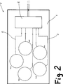
1 zeigt eine schematische Darstellung der Anordnung der Sensorvorrichtung V gemäß einem Ausführungsbeispiel der vorliegenden Erfindung. 1 shows a schematic representation of the arrangement of the sensor device V according to an embodiment of the present invention.
Auf einer im Wesentlichen ebenen Grundplatte 1 der Sensorvorrichtung V ist eine Mehrzahl von ebenen Magnetspulen S1 bis S5 angeordnet, wobei die Magnetspulen S1 bis S5 auf der ebenen Oberfläche der Grundplatte 1 angeordnet oder in der Grundplatte 1 versenkt ausgebildet sind. Die Grundplatte 1 kann beispielsweise als eine Leiterplatte ausgeführt werden, die eine vorbestimmte Dicke aufweist, wobei die Mehrzahl der ebenen Magnetspulen S1 bis S5, die nachstehend vereinfacht als Spulen S1 bis S5 bezeichnet werden, jeweils entsprechende Anschlussleitungen 2 aufweisen. Mittels der Anschlussleitungen werden den jeweiligen Spulen S1 bis S5 Ströme zugeführt, so dass ein Magnetfeld ausgebildet wird.On a substantially flat base plate 1 the sensor device V is arranged a plurality of planar magnetic coils S1 to S5, wherein the magnetic coils S1 to S5 on the flat surface of the base plate 1 arranged or in the base plate 1 sunk. The base plate 1 For example, it may be embodied as a printed circuit board having a predetermined thickness, wherein the plurality of planar magnetic coils S1 to S5, which will be referred to simply as coils S1 to S5 hereinafter, respectively have respective connecting leads 2 exhibit. By means of the connection lines, currents are supplied to the respective coils S1 to S5, so that a magnetic field is formed.
In der Darstellung von 1 sind die jeweiligen Anschlussleitungen an ein erstes Steckerelement 3 geführt, mittels dessen in Verbindung mit einem zweiten Steckerelement 4 eine Steckverbindung gebildet werden kann. Die beiden Steckerelemente 3 und 4 stehen in Verbindung mit einer Steuerungseinheit 5, so dass bei bestehender Steckverbindung mittels der Steckerelemente 3 und 4 die Steuerungseinheit 5 den Spulen S1 bis S5 Ströme zuführen kann zur Bildung des gewünschten Magnetfelds sowie Veränderungen in den elektrischen Werten der Spulen S1 bis S5 erfassen kann.In the presentation of 1 are the respective connection lines to a first connector element 3 guided, by means of which in conjunction with a second connector element 4 a plug connection can be formed. The two connector elements 3 and 4 stand in connection with a control unit 5 , so that with existing connector by means of the connector elements 3 and 4 the control unit 5 can supply currents to the coils S1 to S5 can detect the desired magnetic field and detect changes in the electrical values of the coils S1 to S5.
In der Darstellung von 1 sind die mehreren Spulen S1 bis S5 in gleichartiger Form dargestellt, wobei die vorliegende Erfindung hierauf nicht festgelegt ist und die Spulen S1 bis S5 jeweils unterschiedliche Größe und Ausführung (z. B. Durchmesser, äußere Form und Wicklungssinn) aufweisen können. Vorzugsweise werden den Spulen S1 bis S5 mittels der Steuerungseinheit 5 gleiche Ströme zugeführt, wobei jedoch die Ströme hinsichtlich Stromstärke und Stromrichtung auch unterschiedlich sein können, insbesondere, wenn die Spulen S1 bis S5 zumindest teilweise (beispielsweise hinsichtlich Wicklungssinn bzw. Wicklungsrichtung, Windungsanzahl) unterschiedlich ausgeführt sind. Die Spulen S1 bis S5 können somit zumindest teilweise einen gleichartigen oder unterschiedlichen Wicklungssinn aufweisen.In the presentation of 1 For example, the plurality of coils S1 to S5 are shown similarly, and the present invention is not set to this, and the coils S1 to S5 may each be different in size and design (eg, diameter, outer shape, and winding sense). Preferably, the coils S1 to S5 by means of the control unit 5 However, the currents can also be different in terms of current and current direction, in particular if the coils S1 to S5 are at least partially (for example, in terms of winding sense or winding direction, number of turns) designed differently. The coils S1 to S5 can thus at least partially have a similar or different winding sense.
Während des Betriebs der Sensorvorrichtung V werden zumindest einigen und vorzugsweise sämtlichen Spulen S1 bis S5 jeweilige Ströme zur Ausbildung eines gewünschten Magnetfelds durch jede Spule S1 bis S5 zugeführt.During operation of the sensor device V, at least some and preferably all of the coils S1 to S5 are supplied with respective currents for forming a desired magnetic field through each coil S1 to S5.
In der Darstellung gemäß 1 sind beispielsweise die Spulen S1 bis S5 in Form einer Würfel-5-Anordnung (erstes Muster der Ausbildung der Spulen) gezeigt, wobei an vier Ecken eines Quadrats jeweils eine Spule S1, S2, S4 und S5 und in der Mitte zwischen sämtlichen Spulen S1, S2, S4, S5 die dritte Spule S3 punkt- oder spielgelsymmetrisch angeordnet ist.In the illustration according to 1 For example, coils S1 to S5 are shown in the form of a cube-5 array (first pattern of coils), with coils S1, S2, S4 and S5 at four corners of a square, and midway between all coils S1, S2, S4, S5, the third coil S3 is arranged point or play gel symmetrical.
Neben der Möglichkeit, die Spulen S1 bis S5 jeweils mit der Steuerungseinheit 5 über eigene Zuleitungen zur individuellen Ansteuerung zu verbinden, besteht die Möglichkeit, dass einige und vorzugsweise sämtliche der mehreren Spulen S1 bis S5 einen gemeinsamen Rückleiter aufweisen, und jede Spule S1 bis S5 der Sensorvorrichtung V mit der Steuerungseinheit 5 lediglich über eine Anschlussleitung verbunden ist.In addition to the possibility of coils S1 to S5 each with the control unit 5 There is the possibility that some and preferably all of the several coils S1 to S5 have a common return conductor via their own supply lines for individual activation, and each coil S1 to S5 of the sensor device V with the control unit 5 only connected via a connecting line.
In dem Ausführungsbeispiel gemäß 1 sind 5 gleichartige oder teilweise unterschiedliche Spulen gezeichnet, wobei die Leitungsführung innerhalb jeder Spule S1 bis S5 spiralförmig ausgebildet ist. Dies ist beispielhaft in Verbindung mit der ersten Spule S1 gezeigt und gilt für sämtliche Spulen S1 bis S5. Die Grundplatte 1 besteht aus einem isolierenden Material, und es können die Spulen S1 bis S5 sowie die Anschlussleitungen 2 in Form einer gedruckten Schaltung oder mittels einer aufgebrachten Drahtwicklung (mit einer vorbestimmten Drahtdicke) ausgebildet werden. Weisen die jeweiligen Spulen S1 bis S5 Anschlussleitungen 2 mit zwei Leitern zum Herstellen einer Verbindung zur Steuerungseinheit 5 auf, sind auf der Grundplatte 1 die Spulen S1 bis S5 elektrisch nicht miteinander verbunden. Die Spulen S1 bis S5 können auch in der Grundplatte 1 zum erreichen einer (weitgehend) glatten oder ebenen Oberfläche der Grundplatte 1 in dieser versenkt (d. h. mit der Oberfläche der Grundplatte 1 bündig) angeordnet sein oder vollständig in das Material der Grundplatte 1 eingebettet sein.In the embodiment according to 1 5 similar or partially different coils are drawn, wherein the wiring within each coil S1 to S5 is formed spirally. This is shown by way of example in connection with the first coil S1 and applies to all coils S1 to S5. The base plate 1 consists of an insulating material, and it can be the coils S1 to S5 and the connecting cables 2 be formed in the form of a printed circuit or by means of an applied wire winding (with a predetermined wire thickness). Do the respective coils S1 to S5 have connecting cables 2 with two conductors to connect to the control unit 5 on, are on the base plate 1 the coils S1 to S5 are not electrically connected to each other. The coils S1 to S5 can also be in the base plate 1 to achieve a (largely) smooth or even surface of the base plate 1 sunk in this (ie with the surface of the base plate 1 flush) or completely in the material of the base plate 1 be embedded.
2 zeigt eine alternative Anordnung der vorstehend angegebenen Spulen, wobei in der alternativen Anordnung von 2 die Spulen mit M1 bis M5 bezeichnet werden (zweites Muster der Ausbildung der Spulen). 2 shows an alternative arrangement of the above coils, wherein in the alternative arrangement of 2 the coils are designated M1 to M5 (second pattern of coil formation).
Im Vergleich zur Anordnung gemäß 1 (Würfel-5-Anordnung) sind die Spulen M1 bis M5 ringförmig angeordnet. Die weitere Ausgestaltung ist gleichartig zu derjenigen von 1, wobei die Anschlussleitungen 2 zu den jeweiligen Spulen M1 bis M5 zweiadrig ausgeführt sein können, oder lediglich eine Anschlussleitung bilden können, wobei die Spulen M1 bis M5 in diesem Fall einen gemeinsamen Rückleiter aufweisen.Compared to the arrangement according to 1 (Cube-5 arrangement), the coils M1 to M5 are arranged in a ring. The further embodiment is similar to that of 1 , where the connecting cables 2 to the respective coils M1 to M5 may be made two-wire, or may form only a connecting line, wherein the coils M1 to M5 have in this case a common return conductor.
In der Darstellung von 2 ist ferner die Steuerungseinheit 5 beispielhaft auf der Grundplatte 1 angeordnet, so dass ohne eine durch Steckerelemente gebildete Steckverbindung eine elektrische Verbindung zwischen den Spulen M1 bis M5 und der Steuerungseinheit 5 gebildet werden kann.In the presentation of 2 is also the control unit 5 by way of example on the base plate 1 arranged so that without a connector formed by plug connection, an electrical connection between the coils M1 to M5 and the control unit 5 can be formed.
In gleicher Weise wie bei der Anordnung von 1 ist die Grundplatte 1 bei der Anordnung von 2 aus einem isolierenden Material gebildet oder zumindest mit einer Isolierschicht ausgestattet, so dass die auf der ebenen Oberfläche der Grundplatte 1 ausgebildeten Spulen M1 bis M5 elektrisch voneinander getrennt sind. Die Spulen M1 bis M5 können hierbei gleichartig oder unterschiedlich ausgeführt sein, und es können einige der Spulen M1 bis M5 und vorzugsweise sämtliche der Spulen M1 bis M5 mittels der Steuerungseinheit 5 angesteuert werden. Bei der Ansteuerung werden entsprechende Ströme zugeführt, so dass ein jeweiliges Magnetfeld in Spulen M1 bis M5 ausgebildet wird. Die Spulen M1 bis M5 können einen gleichartigen oder unterschiedlichen Wicklungssinn aufweisen, wobei die Spulen M1 bis M5 in Verbindung mit einer spiralförmigen Wicklung aufgebaut sind, wie sie bei der ersten Spule S1 von 1 gezeigt ist.In the same way as in the arrangement of 1 is the base plate 1 in the arrangement of 2 formed from an insulating material or at least equipped with an insulating layer, so that on the flat surface of the base plate 1 formed coils M1 to M5 are electrically isolated from each other. The coils M1 to M5 may hereby be identical or different, and some of the coils M1 to M5 and preferably all of the coils M1 to M5 may be implemented by means of the control unit 5 be controlled. When driving corresponding currents are supplied, so that a respective magnetic field is formed in coils M1 to M5. The coils M1 to M5 may have a similar or different winding sense, wherein the coils M1 to M5 are constructed in conjunction with a spiral winding, as in the first coil S1 of 1 is shown.
Die Sensorvorrichtung V gemäß der Darstellung in 1 sowie die Sensorvorrichtung gemäß der Darstellung in 2 können mittels einer externen Verbindungseinrichtung mit einer weiteren Auswertungseinrichtung oder einem zentralen Steuerungscomputer verbunden werden.The sensor device V as shown in FIG 1 and the sensor device as shown in FIG 2 can be connected by means of an external connection device with a further evaluation device or a central control computer.
Die Wirkungsweise der Sensorvorrichtung V gemäß der Darstellung in den 1 und 2 sowie die Bildung eines Sensorsystems werden nachstehend im Einzelnen unter Bezugnahme auf die 4 bis 6 beschrieben.The operation of the sensor device V as shown in the 1 and 2 and the formation of a sensor system will be described below in detail with reference to FIGS 4 to 6 described.
3 zeigt in vereinfachter Darstellung die Anordnung der Spulen S1 bis S5 auf der Grundplatte 1 gemäß 1, wobei eine Schnittlinie A-A eingezeichnet ist. 4 zeigt eine Schnittdarstellung der Anordnung gemäß 3 entlang der Schnittlinie A-A, wobei über der Grundplatte 1 mit den entsprechend der Schnittdarstellung schematisch gezeigten Spulen S1, S3 und S2 ein Erfassungsobjekt 7 gezeigt ist, das im Abstand D über der Sensorvorrichtung V angeordnet ist. Zur Vereinfachung der Darstellung ist das Erfassungsobjekt 7, das nachstehend als Objekt 7 bezeichnet wird, beispielhaft als eine einfache Scheibe und sind die Spulen S1, S3 und S2 vereinfacht und schematisch auf der Oberfläche der Grundplatte 1 dargestellt. 3 shows a simplified representation of the arrangement of the coils S1 to S5 on the base plate 1 according to 1 , wherein a section line AA is drawn. 4 shows a sectional view of the arrangement according to 3 along the section line AA, being above the base plate 1 with the according to the sectional view schematically shown coils S1, S3 and S2, a detection object 7 is shown, which is arranged at a distance D above the sensor device V. To simplify the illustration, the object to be recorded is 7 , hereinafter referred to as object 7 is exemplified as a simple disc and the coils S1, S3 and S2 simplified and schematically on the surface of the base plate 1 shown.
Das Objekt 7 ist in der Darstellung von 3 und der weiteren Betrachtung hierzu als eine kreisförmige Scheibe mit der Dicke d dargestellt, wobei jedoch eine andere Ausführung oder andere Proportionen des Objekts 7 ebenfalls möglich sind. Die vorliegende Erfindung ist auf die Ausbildung einer kreisförmigen Scheibe nicht beschränkt. Vorzugsweise ist jedoch das Objekt 7 symmetrisch über den Spulen S1 bis S5 oder M1 bis M5 angeordnet.The object 7 is in the representation of 3 and for further consideration, illustrated as a circular disk of thickness d, but with a different design or proportions of the object 7 are also possible. The present invention is not limited to the formation of a circular disk. Preferably, however, is the object 7 arranged symmetrically over the coils S1 to S5 or M1 to M5.
Im Sinne der vorliegenden Erfindung bilden die mehreren Spulen S1 bis S5 und M1 bis M5 in Verbindung mit der Grundplatte 1, den Anschlussleitungen 2 und der Steuerungseinheit 5 (und fallweise mit den Steckerelementen 3 und 4) die Sensorvorrichtung V, und die Sensorvorrichtung V bildet zusammen mit dem (zu erfassenden) Objekt 7 das Sensorsystem.For the purposes of the present invention, the plurality of coils S1 to S5 and M1 to M5 in conjunction with the base plate 1 , the connecting cables 2 and the control unit 5 (and occasionally with the connector elements 3 and 4 ) the sensor device V, and the sensor device V together with the (to be detected) object 7 the sensor system.
Das Sensorsystem bzw. die Sensorvorrichtung V sind ausgebildet zur Erfassung von Bewegungen und Positionen des Objekts 7 relativ zu der Sensorvorrichtung V. Wird zur Vereinfachung der Betrachtungen die Sensorvorrichtung V als ortsfest angesehen, wird eine Bewegung oder eine Position des Objekts 7 im Vergleich zur ortsfesten Sensorvorrichtung V ermittelt. Die Positionen oder Bewegungen des Objekts 7 können in sämtlichen drei Raumrichtungen vorliegen, einschließlich einer Drehung des Objekts und eines Verkippens des Objekts 7 relativ zur Grundplatte 1 mit den Spulen S1 bis S5 oder M1 bis M5. 5 zeigt in diesem Zusammenhang die Schnittdarstellung der Anordnung gemäß 3 entlang der Schnittlinie A-A, wobei das Objekt 7 um den Winkel α zur horizontalen und damit zur Anordnung der Grundplatte 1 einschließlich der jeweiligen Spulen S1 bis S5 und M1 bis M5 geneigt, bzw. gekippt ist.The sensor system or the sensor device V are designed to detect movements and positions of the object 7 relative to the sensor device V. If, for the sake of simplification of the considerations, the sensor device V is considered to be stationary, a movement or a position of the object becomes 7 determined in comparison to the stationary sensor device V. The positions or movements of the object 7 may be present in all three spatial directions, including rotation of the object and tilting of the object 7 relative to the base plate 1 with the coils S1 to S5 or M1 to M5. 5 shows in this context the sectional view of the arrangement according to 3 along the section line AA, where the object 7 by the angle α to the horizontal and thus to the arrangement of the base plate 1 including the respective coils S1 to S5 and M1 to M5 inclined or tilted.
Zur Erfassung der jeweiligen Bewegungen des Objekts 7 ist die Steuerungseinheit 5 in einer in 6 gezeigten Weise aufgebaut. Die Steuerungseinheit 5 umfasst eine Zentraleinheit 8, mit der jeweilige Schnittstellen 9 verbunden sind, über die die Zentraleinheit 8 die jeweiligen Spulen S1 bis S5 und M1 bis M5 ansteuert und insbesondere zur Erzeugung eines Magnetfelds Ströme zuführt. Die Schnittstellen 9 können auch in der Zentraleinheit 8 integriert sein. Einzelheiten des Betriebs der Sensorvorrichtung V oder des Sensorsystems können auf einer Anzeigeeinrichtung 10 zur Anzeige gebracht werden. Zu einer Speichereinrichtung 11 sind Programme und zusätzliche Daten, wie beispielsweise auch Kennfelder, gespeichert, auf die bei Bedarf die Zentraleinheit 8 zugreifen kann.To capture the respective movements of the object 7 is the control unit 5 in an in 6 constructed manner shown. The control unit 5 includes a central unit 8th , with the respective interfaces 9 connected via the the central unit 8th drives the respective coils S1 to S5 and M1 to M5 and in particular supplies currents for generating a magnetic field. The interfaces 9 can also be in the central unit 8th be integrated. Details of the operation of the sensor device V or the sensor system may be on a display device 10 be displayed. To a storage device 11 Programs and additional data, such as maps, are stored on which, if necessary, the central unit 8th can access.
Bei dem Betrieb der Vorrichtung V werden mittels der Zentraleinheit 8 der Steuerungseinheit 5 die jeweils zugehörigen Schnittstellen 9 einiger oder sämtlicher Spulen S1 bis S5 und M1 bis M5 angesteuert, so dass den jeweiligen Spulen S1 bis S5 und M1 bis M5 entsprechende Ströme zur Ausbildung eines Magnetfelds zugeführt werden. Dies erfolgt unter Steuerung der Zentraleinheit 8, wobei auf entsprechende Programme und grundlegende Daten der Speichereinrichtung 11 zugegriffen werden kann. Bedarfsabhängig kann die Steuerungseinheit 5 alle oder nur einen ausgewählten Teil der Spulen S1 bis S5 und M1 bis M5 ansteuern und auswerten. Jede Spule S1 bis S5 und M1 bis M5 kann einzeln (und mit individuellen elektrischen Größen) angesteuert werden, ungeachtet des gewählten Musters der Anordnung der Spulen S1 bis S5 und M1 bis M5 gemäß des 1 und 2.In the operation of the device V are by means of the central unit 8th the control unit 5 the respective associated interfaces 9 some or all of the coils S1 to S5 and M1 to M5 are driven, so that the respective coils S1 to S5 and M1 to M5 corresponding currents are supplied to form a magnetic field. This is done under control of the central unit 8th , referring to appropriate programs and basic data of the storage device 11 can be accessed. Depending on demand, the control unit 5 all or only a selected part of the coils S1 to S5 and M1 to M5 control and evaluate. Each coil S1 to S5 and M1 to M5 can be driven individually (and with individual electrical quantities) irrespective of the selected pattern of the arrangement of the coils S1 to S5 and M1 to M5 according to FIG 1 and 2 ,
Befindet sich in der Nähe der Spulen S1 bis S5 oder M1 bis M5 kein Gegenstand aus einem leitenden Material und/oder einem magnetischen Material, werden die Magnetfelder der jeweiligen Spulen S1 bis S5 und M1 bis M5 nicht beeinflusst und verbleiben in dem Zustand gemäß ihrer jeweiligen Ansteuerung durch die Steuerungseinheit 5. Erfassbare Änderungen treten dabei nicht auf.If there is no article of conductive material and / or magnetic material in the vicinity of the coils S1 to S5 or M1 to M5, the magnetic fields of the respective coils S1 to S5 and M1 to M5 are unaffected and remain in the state according to their respective ones Control by the control unit 5 , There are no detectable changes.
Befindet sich jedoch gemäß der Darstellung in den 3 bis 5 ein Gegenstand aus einem leitenden und/oder magnetischen Material, wie beispielsweise das Objekt 7, in der Nähe der Grundplatte 1 und damit der Spulen S1 bis S5 oder M1 bis M5, wird das Magnetfeld jeder einzelnen Spule oder zumindest eines Teils der Spulen S1 bis S5 und M1 bis M5 beeinflusst und damit verändert, so dass diese Veränderung mittels der Steuerungseinheit 5 und gemäß 6 speziell durch die Zentraleinheit 8 erfasst werden kann. Es kann hierbei erfasst werden, wenn sich insgesamt die Magnetfelder der einzelnen Spulen S1 bis S5 und M1 bis M5 in gleicher Weise ändern, oder wenn die Änderung bei einzelnen Spulen gegenüber anderen Spulen unterschiedlich ist. Es können alle auf der Grundplatte angeordneten Spulen S1 bis S5 und M1 bis M5 angesteuert und hinsichtlich auftretender Änderungen ausgewertet werden, oder es kann nur ein Teil der Spulen S1 bis S5 und M1 bis M5 angesteuert und dann entsprechend ausgewertet werden.However, as shown in the 3 to 5 an article of a conductive and / or magnetic material, such as the object 7 , near the base plate 1 and thus the coils S1 to S5 or M1 to M5, the magnetic field of each coil or at least a part of the coils S1 to S5 and M1 to M5 is influenced and changed so that this change by means of the control unit 5 and according to 6 especially by the central unit 8th can be detected. In this case, it can be detected if, in total, the magnetic fields of the individual coils S1 to S5 and M1 to M5 change in the same way, or if the change in individual coils differs from other coils. All the coils S1 to S5 and M1 to M5 arranged on the base plate can be activated and evaluated with regard to changes occurring, or only a part of the coils S1 to S5 and M1 to M5 can be activated and then evaluated accordingly.
Der letztere Fall ist beispielsweise in 5 dargestellt, wobei das Objekt 7, das zur Vereinfachung der Darstellung und der Überlegungen als ebene Scheibe ausgebildet ist, um einen Winkel α geneigt über den Spulen S1 bis S5 und M1 bis M5 angeordnet ist. Dies erfolgt in einem Abstand zu der Oberfläche der Grundplatte 1, so dass eine Beeinflussung der jeweiligen Magnetfelder der Spulen S1 bis S5 und M1 bis M5 möglich ist. Im Einzelnen wird in der Steuerungseinheit 5 durch die Zentraleinheit 8 die jeweiligen Änderungen der Magnetfelder der einzelnen Spulen S1 bis S5 und M1 bis M5 oder sämtlicher Spulen S1 bis S5 und M1 bis M5 in Verbindung mit einer Änderung der angelegten physikalischen Größen (elektrische Größen wie Strom, Spannung, Frequenz) erfasst und ausgewertet, wobei Änderungen jeder einzelnen Spule S1 bis S5 und M1 bis M5 auf der Grundplatte 1 ermittelt und gespeichert werden. Die entsprechenden Erfassungsergebnisse der Änderungen des Magnetfelds der Spulen S1 bis S5 und M1 bis M5 (sämtlicher oder einzelner Spulen) infolge eines Einflusses des Objekts 7 werden jeweils miteinander verglichen und können auch mit vorbestimmten Werten verglichen werden, die im Rahmen von Referenzmessungen und Kalibriervorgängen gebildet und beispielsweise auch in Form eines Kennfelds gespeichert werden können. Mittels der ausgewerteten Erfassungsergebnisse kann die Bewegung oder Position des über den Spulen S1 bis S5 und M1 bis M5 angeordneten Gegenstands, wie beispielsweise des Objekts 7, bestimmt werden. Insbesondere sind sämtliche dreidimensionalen Bewegungen einschließlich eines Kippens und einer Drehung mittels der erfindungsgemäßen Vorrichtung V erfassbar.The latter case is for example in 5 shown, where the object 7 , which is designed to simplify the illustration and the considerations as a flat disc, an angle α is arranged inclined over the coils S1 to S5 and M1 to M5. This is done at a distance to the surface of the base plate 1 , so that an influence of the respective magnetic fields of the coils S1 to S5 and M1 to M5 is possible. In detail, in the control unit 5 through the central unit 8th the respective changes of the magnetic fields of the individual coils S1 to S5 and M1 to M5 or all of the coils S1 to S5 and M1 to M5 are detected and evaluated in conjunction with a change in the applied physical quantities (electrical quantities such as current, voltage, frequency), with changes each individual coil S1 to S5 and M1 to M5 on the base plate 1 be determined and stored. The corresponding detection results of changes in the magnetic field of the coils S1 to S5 and M1 to M5 (all or individual coils) due to an influence of the object 7 are each compared with each other and can also be compared with predetermined values that can be formed in the context of reference measurements and calibration processes and stored, for example, in the form of a map. By means of the evaluated detection results, the movement or position of the object arranged above the coils S1 to S5 and M1 to M5, such as, for example, the object 7 to be determined. In particular, all three-dimensional movements including a tilting and a rotation by means of the device V according to the invention can be detected.
Mit der Bereitstellung einer Mehrzahl unabhängig voneinander anzusteuernder und mit Strömen zu versorgender Spulen S1 bis S5 und M1 bis M5 und insbesondere mit fünf auf der Grundplatte 1 nach einem vorbestimmten Muster angeordneten Spulen S1 bis S5 und M1 bis M5, besteht die Möglichkeit einer vollständigen dreidimensionalen Erfassung sämtlicher Bewegungen in allen Raumrichtungen und einschließlich einer Drehung und eines Verkippens des Objekts 7. Es ist auf diese Weise gewährleistet, dass eine beliebige Relativbewegung zwischen einem Gegenstand, beispielsweise dem Objekt 7, und der Grundplatte 1 (der Sensorvorrichtung V) erfasst werden kann.With the provision of a plurality of coils S1 to S5 and M1 to M5 to be supplied independently of each other and to be supplied with currents, and in particular to five on the base plate 1 According to a predetermined pattern arranged coils S1 to S5 and M1 to M5, there is the possibility of a complete three-dimensional detection of all movements in all spatial directions and including a rotation and a tilting of the object 7 , It is ensured in this way that any relative movement between an object, for example, the object 7 , and the base plate 1 (the sensor device V) can be detected.
Mit der erfindungsgemäßen Anordnung der Sensorvorrichtung V und des mit der Sensorvorrichtung V gebildeten Sensorsystems (Erfassungssystem) sind vielfältige Anwendungen in beispielsweise Haushaltsgeräten für private Haushalte oder Industriemaschinen denkbar, bei denen eine Relativbewegung zwischen verschiedenen Körpern zu erfassen sind. Hierbei kann die Bewegung eines Körpers, der als Objekt 7 betrachtet werden kann, erfasst werden, wenn dieser Körper aus einem magnetischen oder elektrisch leitenden Material besteht. Vorzugsweise besteht der Körper oder das Objekt 7 aus einem Metall oder einem Verbundmaterial mit entsprechenden Metallkomponenten. In der Darstellung der 3 bis 5 wird zur Vereinfachung der Überlegungen eine Metallscheibe mit vorbestimmter Dicke betrachte. Das Objekt 7 besteht somit aus einem leitenden und/oder magnetischen Material, so dass bei einer Anordnung des Objekts in der Nähe der Grundplatte 1 der Sensorvorrichtung V und damit der Spulen S1 bis S5 und M1 bis M5 die jeweiligen Magnetfelder der Spulen in gleicher oder unterschiedlicher Weise bei einer Bewegung des Objekts 7 oder des Körpers oder einer Anordnung in der Nähe der Grundplatte 1 beeinflusst werden. Besteht somit der Körper aus einem leitenden und/oder magnetischen Material, kann die Sensorvorrichtung V direkt in der Nähe entsprechender Teile des Körpers angeordnet werden. Andernfalls wird ein Sensorsystem gebildet, in dem an dem Körper, dessen Bewegung zu erfassen ist, das Objekt 7 angeordnet. Mit der vorstehend beschriebenen Anordnung mit dem einfachen Aufbau und Möglichkeit, metallene und/oder magnetische Objekte, beispielsweise in Form einer ebenen Scheibe zu erfassen, wird nur eine geringe Bautiefe benötigt, so dass auch im Hinblick auf die erforderliche Baugröße (Abmessungen) vielfältige Verwendungsmöglichkeiten bestehen.With the arrangement according to the invention of the sensor device V and of the sensor system V formed sensor system (detection system) diverse applications in, for example, domestic appliances for households or industrial machines are conceivable in which to detect a relative movement between different bodies. Here, the movement of a body, as an object 7 can be considered, if this body consists of a magnetic or electrically conductive material. Preferably, the body or object exists 7 of a metal or a composite material with corresponding metal components. In the presentation of the 3 to 5 For the sake of simplicity, consider a metal disk of predetermined thickness. The object 7 is thus made of a conductive and / or magnetic material, so that in an arrangement of the object in the vicinity of the base plate 1 the sensor device V and thus the coils S1 to S5 and M1 to M5 the respective magnetic fields of Coils in the same or different ways during a movement of the object 7 or the body or an arrangement near the baseplate 1 to be influenced. Thus, if the body is made of a conductive and / or magnetic material, the sensor device V can be placed directly in the vicinity of corresponding parts of the body. Otherwise, a sensor system is formed in which on the body whose movement is to be detected, the object 7 arranged. With the arrangement described above with the simple structure and ability to detect metal and / or magnetic objects, for example in the form of a flat disc, only a small depth is required, so that in terms of the required size (dimensions) a variety of uses exist ,
Die 7A und 7B zeigen beispielhaft verschiedene Ausführungen des Objekts 7.The 7A and 7B show exemplary embodiments of the object 7 ,
7A zeigt eine einfache Ausführung des Objekts 7 als eine erste ebene Scheibe 71 aus einem homogenen metallenen und/oder magnetischen Werkstoff mit einer vorbestimmten Dicke (beispielsweise d in 4). 7B zeigt eine weitere Variante des Objekts 7 als eine zweite ebene Scheibe 72, die erste vorbestimmte Bereiche 73 aufweist, bestehend aus einem ersten Material, und weitere zweite vorbestimmte Bereiche 74 aufweist, bestehend aus einem zweiten Material, das hinsichtlich seiner elektrischen und/oder magnetischen Eigenschaften unterschiedlich ist zum ersten Material. Beispielsweise kann die zweite Scheibe 72 in den ersten vorbestimmten Bereichen ein metallisches und/oder magnetisches Material aufweisen, und in den zweiten vorbestimmten Bereichen 74 ein nicht leitendes und/oder nicht magnetisches Material aufweisen. 7A shows a simple execution of the object 7 as a first flat disc 71 of a homogeneous metal and / or magnetic material having a predetermined thickness (for example, d in 4 ). 7B shows another variant of the object 7 as a second level disk 72 , the first predetermined areas 73 comprising, consisting of a first material, and further second predetermined areas 74 comprising, consisting of a second material which is different in terms of its electrical and / or magnetic properties to the first material. For example, the second disc 72 in the first predetermined regions comprise a metallic and / or magnetic material, and in the second predetermined regions 74 comprise a non-conductive and / or non-magnetic material.
In 7B sind die Bereiche 73 und 74 als Kreissektoren dargestellt, wobei entsprechende Sektoren einander diametral bezüglich eines gedachten Mittelpunkts der zweiten Scheibe 72 gegenüberliegen können oder auch eine davon abweichende Anordnung aufweisen können, wie sie beispielsweise in 7B gezeigt ist. Es können auch mehrere Bereiche mit weiteren unterschiedlichen Materialien vorgesehen sein, wobei auch Ausschnitte oder Öffnungen entsprechender Größe in der Scheibe angeordnet werden können. Beispielsweise kann in diesem Zusammenhang eine ansonsten homogen bezüglich des Materials und der Dicke ausgeführte Scheibe an vorbestimmten Stellen Ausschnitte oder Lücken im Material aufweisen. Eine reine Drehung kann mit einem Objekt 7 bzw. de vorstehend beschriebenen Scheibe erfasst werden, wenn die Änderungen der Eigenschaften des Objekts 7 (Änderungen der Materialeigenschaften durch andere Materialien oder Materiallücken) in Umfangsrichtung des beispielsweise scheibenförmigen Objekts 7 auftreten.In 7B are the areas 73 and 74 represented as circular sectors, wherein corresponding sectors are diametrically opposed to an imaginary center of the second disc 72 may be opposite or may have a different arrangement, as in example 7B is shown. It is also possible to provide a plurality of regions with further different materials, whereby also cutouts or openings of corresponding size can be arranged in the disk. For example, in this context, an otherwise homogeneous with respect to the material and the thickness of the disc at predetermined locations have cutouts or gaps in the material. A pure rotation can be done with an object 7 or the disc described above are detected when the changes in the properties of the object 7 (Changes in material properties by other materials or material gaps) in the circumferential direction of the example disc-shaped object 7 occur.
Im Falle der Verwendung eines Objekts 7 gemäß der zweiten Scheibe 72 kann eine Ausgangsposition, Ruheposition oder Nullposition des Objekts 7 relativ zur Grundplatte 1 ungeachtet einer symmetrischen Anordnung bezüglich der Grundplatte 1 bestimmt und können die entsprechenden Daten gespeichert werden. Relativbewegungen können somit im Rahmen der Auswertung auch im Vergleich zu dieser Ruhe- oder Nullposition bestimmt werden.In case of using an object 7 according to the second disc 72 can be a home position, rest position or zero position of the object 7 relative to the base plate 1 regardless of a symmetrical arrangement with respect to the base plate 1 determines and can be stored the appropriate data. Relative movements can thus be determined in the context of the evaluation also in comparison to this rest or zero position.
In Verbindung mit 7B besteht als alternative Ausführung die Möglichkeit, ausgehend von einer Anordnung des Objekts 7 gemäß der ersten Scheibe 71 in vorbestimmten Kreissektoren die Dicke der Scheibe zu verändern, so dass in diesen Sektoren unterschiedliche elektrische und magnetische Eigenschaften auftreten. Diese können jeweils erfasst werden, insbesondere im Hinblick auf eine Drehung des Objekts 7 bzw. der Scheibe um ihren gedachten Mittelpunkt ohne weitere Bewegung in einer der drei Raumrichtungen oder ein Verkippen.Combined with 7B As an alternative embodiment, there is the possibility of starting from an arrangement of the object 7 according to the first disc 71 in predetermined circular sectors to change the thickness of the disc, so that different electrical and magnetic properties occur in these sectors. These can each be detected, in particular with regard to a rotation of the object 7 or the disc around its imaginary center without further movement in one of the three spatial directions or a tilting.
8 zeigt in vereinfachter und schematischer Darstellung die Anwendung der Sensorvorrichtung V und des Sensorsystems zur Erfassung einer Bewegung eines Laugenbehälters 12 in einer Wascheinrichtung 13. Ein mittels Dämpfungs- und Federelementen 14 elastisch und damit beweglich aufgehängter Laugenbehälter 12 kann relativ zu dem Gehäuse der Wascheinrichtung 13 im Betrieb und bei einer Beladung oder Entladung eine Bewegung durchführen, die mittels der Sensorvorrichtung V erfasst werden kann. Die Sensorvorrichtung V ist an dem Gehäuse der Wascheinrichtung 13 angeordnet, während das Objekt 7 mechanisch mit dem Laugenbehälter 12 verbunden ist und seiner Bewegung während der Waschvorgänge und insbesondere während des Schleuderns folgt. Jegliches Verkippen und Schwingen des Laugenbehälters kann erfasst werden. Es besteht auch die Möglichkeit, kleine Bewegungen des Laugenbehälters zu erfassen, wenn dieser vor einem Waschvorgang mit einem Waschgut gefüllt oder danach entladen wird, so dass die Füllmenge des Waschguts und fallweise eine restliche Wassermenge in dem Waschgut bestimmt werden kann. Die Füllmenge des Waschguts kann zur Steuerung oder Regelung des Waschvorgangs verwendet werden. 8th shows in simplified and schematic representation of the application of the sensor device V and the sensor system for detecting a movement of a tub 12 in a washing facility 13 , A by means of damping and spring elements 14 elastic and thus suspended suspended tub 12 can relative to the housing of the washing device 13 perform a movement during operation and during a loading or unloading, which can be detected by means of the sensor device V. The sensor device V is on the housing of the washing device 13 arranged while the object 7 mechanically with the tub 12 is connected and follows its movement during the washing operations and in particular during the spinning. Any tilting and swinging of the tub can be detected. It is also possible to detect small movements of the tub when it is filled with a laundry before a washing process or discharged thereafter, so that the filling amount of the laundry and occasionally a residual amount of water in the laundry can be determined. The filling quantity of the laundry can be used to control or regulate the washing process.
9 zeigt eine weitere verallgemeinerte Anwendung, bei der die Relativbewegung zwischen zwei beliebigen Körpern K1 und K2 bestimmt werden soll. Die möglichen dreidimensionalen Bewegungen sind durch ein rechtwinkliges Achsenkreuz mit einer x,- y- und z-Achse veranschaulicht. Die Sensorvorrichtung V mit den Spulen S1 bis S5 und M1 bis M5 und der Grundplatte 1 ist an dem Körper K2 befestigt, während das Objekt 7 an dem Körper K1 befestigt ist. Bewegen sich beide Körper K1 und K2 relativ zueinander, kann dies erfasst werden. Im Allgemeinen liegt in einem bestimmten Ruhezustand oder Grundzustand ein vorbestimmter Abstand zwischen dem Objekt 7 und der Grundplatte 1 mit den Spulen (S1 bis S5, M1 bis M5). Dieser kann bei Bedarf auch zur Kalibrierung dienen. 9 shows another generalized application in which the relative movement between any two bodies K1 and K2 is to be determined. The possible three-dimensional movements are illustrated by a right-angled axbox with an x, -y and z-axis. The sensor device V with the coils S1 to S5 and M1 to M5 and the base plate 1 is attached to the body K2 while the object 7 attached to the body K1. If both bodies K1 and K2 move relative to each other, this can be detected. in the In general, there is a predetermined distance between the object in a certain rest state or ground state 7 and the base plate 1 with the coils (S1 to S5, M1 to M5). If necessary, this can also be used for calibration.
Die Darstellung gemäß 9 zeigt vielfältige Anwendungen in sämtlichen Bauteilen und Maschinen, bei denen eine derartige Erfassung erforderlich bzw. möglich ist.The representation according to 9 shows a variety of applications in all components and machines where such detection is required or possible.
Mit der vorstehend beschriebenen Sensorvorrichtung V gemäß der vorliegenden Erfindung oder dem Sensorsystem mit der Sensorvorrichtung V und dem beweglichen Objekt 7 besteht die Möglichkeit einer dreidimensionalen Erfassung jeglicher relativer Bewegungen einschließlich eines Verkippens und einer Drehung, wobei lediglich ein geringer Aufwand an mechanischen Einrichtungen und an Montagearbeit erforderlich ist. Mit den beispielsweise fünf Spulen S1 bis S5 und M1 bis M5 in der Darstellung der 1, 2 und 4 wird eine einfache Anordnung bereitgestellt, wobei vorzugsweise auf der Grundplatte 1 bereits vollständig oder zumindest in Teilen die Steuerungseinheit 5 verwirklicht werden kann. Werden die auf der Grundplatte 1 aufgebrachten Spulen S1 bis S5 und M1 bis M5 mit einer weiteren Isolierschicht und/oder Schutzschicht versehen, wird eine sehr haltbare und über eine längere Zeit stabile Sensorvorrichtung V gebildet, die eine sehr geringe Fehleranfälligkeit und eine verbesserte Handhabbarkeit insbesondere bei der Montage aufweist.With the above-described sensor device V according to the present invention or the sensor system with the sensor device V and the movable object 7 There is the possibility of a three-dimensional detection of any relative movements including tilting and rotation, with only a small amount of mechanical equipment and assembly work is required. With the example, five coils S1 to S5 and M1 to M5 in the representation of 1 . 2 and 4 a simple arrangement is provided, preferably on the base plate 1 already completely or at least partially the control unit 5 can be realized. Be the ones on the base plate 1 applied coils S1 to S5 and M1 to M5 provided with a further insulating layer and / or protective layer, a very durable and stable over a longer time sensor device V is formed, which has a very low susceptibility to errors and improved handling, especially during assembly.
Wird hinsichtlich der Dimensionen der Sensorvorrichtung V beispielsweise die Anordnung gemäß 1 betrachtet, kann die Kantenlänge der Grundplatte im Bereich von etwa 50 bis 150 mm liegen, und es kann das (in der vereinfachten und schematischen Darstellung) scheibenförmige Objekt 7 einen Durchmesser von etwa 30 bis 100 mm aufweisen. Die Größe des Objekts 7 und, im Falle einer einfachen Scheibe der jeweilige Durchmesser, steht im Zusammenhang mit der Größe der Anordnung der Grundplatte 1 und der zugehörigen Spulen S1 bis S5 und M1 bis M5. Ebenfalls in dem Zusammenhang steht der Ruheabstand oder Grundabstand zwischen der Grundplatte 1 und dem Objekt 7, der je nach Größe der genannten Komponenten etwa 3 bis 30 mm betragen kann. Es sind somit Anwendungen auch bei einem geringen Einbauplatz möglich.With regard to the dimensions of the sensor device V, for example, the arrangement according to 1 Considering the edge length of the base plate may be in the range of about 50 to 150 mm, and it may be the (in the simplified and schematic representation) disc-shaped object 7 have a diameter of about 30 to 100 mm. The size of the object 7 and, in the case of a simple disc, the respective diameter is related to the size of the arrangement of the base plate 1 and the associated coils S1 to S5 and M1 to M5. Also in this context is the rest distance or base distance between the base plate 1 and the object 7 , which may be about 3 to 30 mm depending on the size of said components. There are thus applications possible even with a small slot.
Des Weiteren besteht die Möglichkeit, auf der Grundplatte 1 an einer vorbestimmten Stelle einen Magnetsensor (oder auch mehrere Sensoren verteilt), beispielsweise in Form zumindest eines dreidimensional messenden Hall-Sensors anzuordnen, mittels dessen unabhängig von der Anwesenheit des Objekts 7 Magnetfelder nach einer Ansteuerung der Spulen S1 bis S5 oder M1 bis M5 durch die Steuerungseinheit 5 erfasst und bedarfsabhängig und über eine entsprechende Stromzufuhr auf vorbestimmte Werte geregelt oder einzelne Spulen individuell angesteuert werden können.Furthermore, there is a possibility on the base plate 1 to arrange at a predetermined location a magnetic sensor (or a plurality of sensors distributed), for example in the form of at least one three-dimensionally measuring Hall sensor, by means of which independent of the presence of the object 7 Magnetic fields after a control of the coils S1 to S5 or M1 to M5 by the control unit 5 recorded and demand-dependent and regulated by an appropriate power supply to predetermined values or individual coils can be controlled individually.
Die vorliegende Erfindung wurde vorstehend anhand von Ausführungsbeispielen und zugehörigen Varianten unter Bezugnahme auf die beigefügten Figuren beschrieben. Es ist jedoch für den auf diesem Gebiet tätigen Fachmann selbstverständlich, dass die Ausgestaltung der vorliegenden Erfindung gemäß den beigefügten Figuren und die für die jeweiligen Bauteile und Komponenten verwendeten Bezugszeichen in den Figuren und der Beschreibung sowie die beispielhaften Angaben nicht einschränkend auszulegen sind. Auch sind die in den einzelnen Figuren angegeben Proportionen nur beispielhaft und lediglich für ein besseres Verständnis schematisch dargestellt. Die Erfindung ist auf die angegebenen Formen und Proportionen nicht beschränkt. Vielmehr werden als zur Erfindung gehörend sämtliche Ausführungsformen und Varianten angesehen, die unter die beigefügten Patentansprüche fallen.The present invention has been described above with reference to embodiments and associated variants with reference to the accompanying figures. However, it will be understood by those skilled in the art that the structure of the present invention, as set forth in the attached figures, and the reference numerals used for the respective components and components, are not to be interpreted as limiting in the figures and the description and by way of example. Also, the proportions given in the individual figures are only exemplary and shown schematically only for a better understanding. The invention is not limited to the specified shapes and proportions. Rather, as belonging to the invention all embodiments and variants are considered, which fall under the appended claims.
ZITATE ENTHALTEN IN DER BESCHREIBUNG QUOTES INCLUDE IN THE DESCRIPTION
Diese Liste der vom Anmelder aufgeführten Dokumente wurde automatisiert erzeugt und ist ausschließlich zur besseren Information des Lesers aufgenommen. Die Liste ist nicht Bestandteil der deutschen Patent- bzw. Gebrauchsmusteranmeldung. Das DPMA übernimmt keinerlei Haftung für etwaige Fehler oder Auslassungen.This list of the documents listed by the applicant has been generated automatically and is included solely for the better information of the reader. The list is not part of the German patent or utility model application. The DPMA assumes no liability for any errors or omissions.
Zitierte PatentliteraturCited patent literature
-
DE 4113745 A1 [0003] DE 4113745 A1 [0003]
-
DE 4127209 A1 [0003] DE 4127209 A1 [0003]
-
DE 102007018616 A1 [0004] DE 102007018616 A1 [0004]