DE202011002356U1 - Integral bumper system with trench-shaped reinforcement structure - Google Patents
Integral bumper system with trench-shaped reinforcement structure Download PDFInfo
- Publication number
- DE202011002356U1 DE202011002356U1 DE202011002356U DE202011002356U DE202011002356U1 DE 202011002356 U1 DE202011002356 U1 DE 202011002356U1 DE 202011002356 U DE202011002356 U DE 202011002356U DE 202011002356 U DE202011002356 U DE 202011002356U DE 202011002356 U1 DE202011002356 U1 DE 202011002356U1
- Authority
- DE
- Germany
- Prior art keywords
- cross member
- bumper system
- frames
- deformation
- trench
- Prior art date
- Legal status (The legal status is an assumption and is not a legal conclusion. Google has not performed a legal analysis and makes no representation as to the accuracy of the status listed.)
- Expired - Lifetime
Links
- 230000002787 reinforcement Effects 0.000 title 1
- 238000005452 bending Methods 0.000 claims abstract description 8
- 238000004519 manufacturing process Methods 0.000 claims abstract description 6
- 230000003014 reinforcing effect Effects 0.000 claims description 12
- 239000000463 material Substances 0.000 claims description 5
- 238000005516 engineering process Methods 0.000 claims 1
- 230000000694 effects Effects 0.000 description 3
- 230000035515 penetration Effects 0.000 description 3
- 230000005540 biological transmission Effects 0.000 description 2
- BUHVIAUBTBOHAG-FOYDDCNASA-N (2r,3r,4s,5r)-2-[6-[[2-(3,5-dimethoxyphenyl)-2-(2-methylphenyl)ethyl]amino]purin-9-yl]-5-(hydroxymethyl)oxolane-3,4-diol Chemical compound COC1=CC(OC)=CC(C(CNC=2C=3N=CN(C=3N=CN=2)[C@H]2[C@@H]([C@H](O)[C@@H](CO)O2)O)C=2C(=CC=CC=2)C)=C1 BUHVIAUBTBOHAG-FOYDDCNASA-N 0.000 description 1
- 239000006096 absorbing agent Substances 0.000 description 1
- 238000010521 absorption reaction Methods 0.000 description 1
- 238000009395 breeding Methods 0.000 description 1
- 230000001488 breeding effect Effects 0.000 description 1
- 238000010276 construction Methods 0.000 description 1
- 230000008094 contradictory effect Effects 0.000 description 1
- 230000008878 coupling Effects 0.000 description 1
- 238000010168 coupling process Methods 0.000 description 1
- 238000005859 coupling reaction Methods 0.000 description 1
- 238000004049 embossing Methods 0.000 description 1
- 230000007613 environmental effect Effects 0.000 description 1
- 230000002349 favourable effect Effects 0.000 description 1
- 238000009434 installation Methods 0.000 description 1
- 238000004088 simulation Methods 0.000 description 1
- 239000013585 weight reducing agent Substances 0.000 description 1
Images

Classifications
-
- B—PERFORMING OPERATIONS; TRANSPORTING
- B60—VEHICLES IN GENERAL
- B60R—VEHICLES, VEHICLE FITTINGS, OR VEHICLE PARTS, NOT OTHERWISE PROVIDED FOR
- B60R19/00—Wheel guards; Radiator guards, e.g. grilles; Obstruction removers; Fittings damping bouncing force in collisions
- B60R19/02—Bumpers, i.e. impact receiving or absorbing members for protecting vehicles or fending off blows from other vehicles or objects
- B60R19/18—Bumpers, i.e. impact receiving or absorbing members for protecting vehicles or fending off blows from other vehicles or objects characterised by the cross-section; Means within the bumper to absorb impact
- B60R2019/1806—Structural beams therefor, e.g. shock-absorbing
- B60R2019/1813—Structural beams therefor, e.g. shock-absorbing made of metal
Landscapes
- Engineering & Computer Science (AREA)
- Mechanical Engineering (AREA)
- Body Structure For Vehicles (AREA)
Abstract
Stoßfängersystem (S) eines Kraftfahrzeuges bestehend im Wesentlichen aus einem einteilig gebildeten quer zur Fahrzeuglängsrichtung angeordnetem Querträger (Q) mit einem Mittelabschnitt (M) und zwei daran angrenzenden Deformationsbereichen (D) zur Aufnahme und Umwandlung von Energie infolge eines Anpralls bzw. Aufpralls auf ein Hindernis, wobei der Querträger in seinem Querschnitt im Wesentlichen als U-Profil oder Hutprofil ausgebildet ist, mit einem Stegbereich (B) und zwei von den zwei Längskanten des Stegbereiches winkelig abstehenden Zargen (Z), wobei die Zargen im Deformationsbereich breiter ausgeformt sind als in angrenzenden Abschnitten des Querträgers, und wobei sich einer Zarge jeweils ein Flanschbereich anschließen kann, der über Durchgänge (L) zur kraftschlüssigen Verbindung, insbesondere Schraubverbindung, des Querträgers und Längsträger verfügen kann, dadurch gekennzeichnet, dass der Querträger über wenigstens eine grabenförmig ausgebildete Verstärkungsstruktur (V) verfügt, wobei diese zumindest teilweise und über die fertigungstechnisch notwendigen Biegeradien hinaus in die Bereiche des Steges (B) und wenigstens einer Zarge (Z) hinein verlaufen.Bumper system (S) of a motor vehicle consisting essentially of a transversely arranged transversely to the vehicle longitudinal direction cross member (Q) with a central portion (M) and two adjacent deformation areas (D) for receiving and converting energy due to an impact or impact on an obstacle , wherein the cross member is formed in its cross section substantially as a U-profile or hat profile, with a web portion (B) and two of the two longitudinal edges of the web portion angularly projecting frames (Z), wherein the frames are formed wider in the deformation region than in adjacent Sections of the cross member, and wherein a frame each have a flange can connect, which may have passages (L) for non-positive connection, in particular screw, the cross member and side member, characterized in that the cross member via at least one trench-shaped Verstärkungsst has structure (V), which at least partially and beyond the production required bending radii in addition to the areas of the web (B) and at least one frame (Z) into it.

Description
Die vorliegende Erfindung betrifft ein Stoßfängersystem gemäß dem Oberbegriff des Anspruchs 1.The present invention relates to a bumper system according to the preamble of claim 1.
In der Fahrzeugindustrie werden heute verstärkte Anforderungen an die Struktursicherheit zum Insassenschutz, aber auch an die maximale Ausnutzung von Bauraum im Hinblick auf größtmögliche Innen- bzw. Kofferraumnutzvolumina bei gleichzeitig möglichst geringem Außenabmessungen gefordert. Hinzu kommen die immer strenger werdenden gesetzlichen Anforderungen an die Umweltverträglichkeit von Antrieb, Karosseriedesign. Dies wiederum hat unmittelbar eine Gewichtsreduktion und aerodynamisch günstige Fahrzeughautgestaltung zur Folge. Um diesen konträren Anforderungen gerecht zu werden, sind im Stand der Technik einige Lösungskonzepte zu finden, welche sich mit der Gestaltung von Stoßfängersystemen an Fahrzeugfront und/oder Rückseite beschäftigen.In the vehicle industry, today, increased demands are made on the structural safety for occupant protection, but also on the maximum utilization of installation space with regard to the greatest possible interior and boot payload volumes, while at the same time having the lowest possible external dimensions. Added to this are the ever stricter legal requirements for the environmental compatibility of the drive, body design. This in turn directly results in weight reduction and aerodynamically favorable vehicle skin design. In order to meet these contradictory requirements, some solution concepts are found in the prior art, which deal with the design of bumper systems on the vehicle front and / or back.
So offenbart die deutsche Patentanmeldung
In den Patentschriften
Die
Insbesondere diese gewichtsreduzierten Stoßfängersysteme haben im Stand der Technik aber den Nachteil, dass sie entweder aus sehr vielen verschiedenen Teilen bestehen und damit kompliziert und aufwändig Herzustellen bzw. Zusammenzubauen sind, oder aber sie haben im Falle eines Fahrzeugunfalls, insbesondere beim Offset-Crash, das heißt bei außermittigem Aufprall auf den frontseitigen oder rückseitigen Stoßfängerquerträger, ein erhöhtes Risiko des Eindringens von Material in den Motor bzw. Kofferraum des Fahrzeugs. Letztgenannter Effekt tritt besonders bei U-förmigen oder Hutprofil-förmigen Querträgergestaltung im Bereich der Längsträgeranbindung auf, da zusätzlich fixierende Crashelemente aus Gewichts- und Platzgründen, wie bei klassischen mehrteiligen Stoßfängersystemen üblich, nicht vorhanden sind. Der Effekt äußert sich dann dadurch, dass die Profilschenkel nach oben oder unten ungeführt parallelogrammartig wegknicken, und dadurch unkalkulierbare Beschädigungen verursachen. Insbesondere Gefahr besteht dann, wenn die Energieaufnahmefunktion durch die Längsträger bei einem stärkeren Offset-Fahrzeugaufprall damit verhindert wird, und stattdessen eine größere Penetration des Innenraums bis zur Fahrgastzelle droht. Dieser Effekt wird dann zusätzlich verstärkt, wenn aufgrund ungünstiger Bauraumeinflüsse der Querträger des Stoßfängersystems in Fahrzeughöhenrichtung (h) ungleichmäßig geformt ist, seine Längsachse in den einzelnen Bereichen versetzt und teilweise antiparallel verläuft.In particular, these weight-reduced bumper systems have in the prior art but the disadvantage that they either consist of many different parts and thus complicated and expensive to manufacture or assemble are, or they have in the event of a vehicle accident, especially in offset crash, that is in the event of an eccentric impact on the front or rear bumper cross member, there is an increased risk of material entering the engine or trunk of the vehicle. The latter effect occurs especially in the case of a U-shaped or hat-shaped cross member design in the region of the side member connection, since additional fixing crash elements for weight and space reasons, as usual in classic multi-part bumper systems, are not available. The effect is then expressed by the fact that the profile legs buckle upwards or downwards unguided parallelogram-like, thereby causing incalculable damage. In particular, there is a risk if the energy absorption function is prevented by the side members in a stronger offset vehicle impact thus, and instead threatens a greater penetration of the interior to the passenger compartment. This effect is then additionally reinforced if due to unfavorable space influences of the cross member of the bumper system in the vehicle height direction (h) is unevenly shaped, offset its longitudinal axis in the individual areas and partially antiparallel.
Aufgabenstellungtask
Aufgabe der Erfindung ist ausgehend vom eingangs beschriebenen Stand der Technik die Schaffung eines gewichtsreduzierten und zugleich belastungsoptimierten Stoßfängersystems für Kraftfahrzeuge. Dabei soll insbesondere das Eindringen jeglicher Stoßfängerbereiche in den Innen bzw. Kofferraum vermieden werden.The object of the invention is based on the above-described prior art, the creation of a weight-reduced and at the same time load-optimized bumper system for motor vehicles. In particular, the penetration of any bumper areas in the interior or trunk should be avoided.
Diese Aufgabe wird durch ein Stoßfängersystem nach den Merkmalen des Anspruchs 1 gelöst. Ausgehend vom Stand der Technik wird ein einteiliges Stoßfängersystem vorgeschlagen, welches im Wesentlichen aus einem U-förmigen oder Hutprofil-förmigen und quer zur Fahrzeuglängsrichtung verlaufenden Querträger gebildet wird, mit einem Mittelabschnitt (M) und zwei daran angrenzenden Deformationsbereichen (D) zur Aufnahme und Umwandlung von Energie infolge eines Anpralls bzw. Aufpralls auf ein Hindernis. Das Profil des Querträger wiederum besitzt einen Stegbereich (B) und zwei von den zwei Längskanten des Stegbereiches winkelig abstehenden Zargen (Z), wobei die Zargen im Deformationsbereich breiter ausgeformt sind als in angrenzenden Abschnitten des Querträgers, und wobei sich einer Zarge jeweils ein Flanschbereich anschließen kann, der über Durchgänge (L) zur kraftschlüssigen Verbindung – insbesondere Schraubverbindung – des Querträgers mit dem Längsträger verfügen kann. Mittelabschnitt und Deformationsbereich sind jeweils durch wenigstens eine grabenförmig ausgebildete Verstärkungsstruktur (V) voneinander getrennt, wobei diese Verstärkungsstruktur zumindest teilweise und über die fertigungstechnisch notwendigen Biegeradien hinaus in die Bereiche des Steges (B) und wenigstens einer Zarge (Z) hinein verlaufen. Dadurch wird erreicht, dass mechanisch eine Entkopplung der einzelnen Abschnitte stattfindet, und bei einem Aufprall die lokale Verformung, insbesondere ein lokales Umbiegen der Zargen nach oben oder unten in der Querprofilebene des Querträgers, sich über die Verstärkungsstruktur auf die Deformationsbereiche ausbreiten kann.This object is achieved by a bumper system according to the features of claim 1. Starting from the prior art, a one-piece bumper system is proposed, which is essentially formed of a U-shaped or hat-shaped and transversely extending to the vehicle longitudinal direction cross member, with a central portion (M) and two adjacent thereto deformation areas (D) for receiving and converting of energy due to an impact on an obstacle. The profile of the cross member in turn has a web portion (B) and two of the two longitudinal edges of the web portion angularly projecting frames (Z), the frames are formed in the deformation region wider than in adjacent sections of the cross member, and wherein each frame can be followed by a flange, which can have passages (L) for non-positive connection - in particular screw - the cross member with the side member. Middle section and deformation region are each separated by at least one trench-shaped reinforcing structure (V), said reinforcing structure extend at least partially and beyond the manufacturing required bending radii in the areas of the web (B) and at least one frame (Z). This ensures that a mechanical decoupling of the individual sections takes place, and in an impact, the local deformation, in particular a local bending of the frames up or down in the transverse profile plane of the cross member, can spread over the reinforcing structure on the deformation regions.
Bevorzugt ist die Verstärkungsstruktur derart beschaffen, dass eine grabenförmige Vertiefung von der Nähe des Randes einer ersten Zarge über den Biegeradius zum Steg hin verläuft, und über die gesamte Stegbreite und den zweiten Biegeradius in die der ersten Zarge gegenüberliegende Zarge hinein ausläuft. Abhängig von der genauen Lage der Längsachse des Mittelabschnittes zu der Verbindungssachse der Deformationsbereiche ist es möglich, einen lotrechten oder schrägen verlauf der Verstärkungsstruktur vorzusehen. Wichtig ist aber, dass die grabenförmige Vertiefung eine Breite und Tiefe aufweist, die signifikant größer als die mittlere Materialstärke des Querträgers ist. Besonders hat sich für die Vertiefungsbreite eine mindestens 6-fache Materialstärke als vorteilhaft erwiesen, wobei die Tiefe mindestens der 2-fachen Materialstärke entsprach.Preferably, the reinforcing structure is such that a trench-shaped recess extends from the vicinity of the edge of a first frame over the bending radius to the web, and over the entire web width and the second bending radius in the first frame opposite edge runs out. Depending on the exact position of the longitudinal axis of the central portion to the connecting axis of the deformation regions, it is possible to provide a vertical or oblique course of the reinforcing structure. But it is important that the trench-shaped depression has a width and depth that is significantly greater than the average material thickness of the cross member. In particular, at least 6 times the material thickness has proved to be advantageous for the recess width, the depth corresponding to at least 2 times the material thickness.
Nachfolgend wird die Erfindung in einer besonders vorteilhaften Ausführungsvarianten an Hand von Zeichnungen erläutert:The invention will be explained in a particularly advantageous embodiment with reference to drawings:
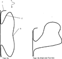
In
In
Die
ZITATE ENTHALTEN IN DER BESCHREIBUNG QUOTES INCLUDE IN THE DESCRIPTION
Diese Liste der vom Anmelder aufgeführten Dokumente wurde automatisiert erzeugt und ist ausschließlich zur besseren Information des Lesers aufgenommen. Die Liste ist nicht Bestandteil der deutschen Patent- bzw. Gebrauchsmusteranmeldung. Das DPMA übernimmt keinerlei Haftung für etwaige Fehler oder Auslassungen.This list of the documents listed by the applicant has been generated automatically and is included solely for the better information of the reader. The list is not part of the German patent or utility model application. The DPMA assumes no liability for any errors or omissions.
Zitierte PatentliteraturCited patent literature
- DE 102007038496 A1 [0003] DE 102007038496 A1 [0003]
- SE 530563 C2 [0004] SE 530563 C2 [0004]
- EP 1888377 B1 [0004, 0004] EP 1888377 B1 [0004, 0004]
- DE 102008026334 A1 [0005] DE 102008026334 A1 [0005]
Claims (8)
Priority Applications (1)
| Application Number | Priority Date | Filing Date | Title |
|---|---|---|---|
| DE202011002356U DE202011002356U1 (en) | 2011-02-03 | 2011-02-03 | Integral bumper system with trench-shaped reinforcement structure |
Applications Claiming Priority (1)
| Application Number | Priority Date | Filing Date | Title |
|---|---|---|---|
| DE202011002356U DE202011002356U1 (en) | 2011-02-03 | 2011-02-03 | Integral bumper system with trench-shaped reinforcement structure |
Publications (1)
| Publication Number | Publication Date |
|---|---|
| DE202011002356U1 true DE202011002356U1 (en) | 2011-04-28 |
Family
ID=43927526
Family Applications (1)
| Application Number | Title | Priority Date | Filing Date |
|---|---|---|---|
| DE202011002356U Expired - Lifetime DE202011002356U1 (en) | 2011-02-03 | 2011-02-03 | Integral bumper system with trench-shaped reinforcement structure |
Country Status (1)
| Country | Link |
|---|---|
| DE (1) | DE202011002356U1 (en) |
Citations (4)
| Publication number | Priority date | Publication date | Assignee | Title |
|---|---|---|---|---|
| SE530563C2 (en) | 2006-11-09 | 2008-07-08 | Gestamp Hardtech Ab | Bumper beam i.e. front bumper beam, for crash box of vehicle, has longitudinal/shallow concavity broadens at same time when concavity deepens towards beam end portions, where concavity becomes deeper than height of webs |
| DE102007038496A1 (en) | 2007-08-14 | 2009-02-26 | Benteler Automobiltechnik Gmbh | Method for manufacturing bumper arrangement of motor vehicle by shaping plate to bumper crossbeam, involves making availability of plate from heat-treatable steel with different wall thicknesses and material characteristics |
| DE102008026334A1 (en) | 2008-05-31 | 2009-12-03 | Dr. Ing. H.C. F. Porsche Aktiengesellschaft | Rear or front cross beam for frame structure of motor vehicle, has crash unit arranged in longitudinal end region, where beam is designed as one-sided open cap profile with cross section depth that change in longitudinal direction of beam |
| EP1888377B1 (en) | 2005-05-25 | 2010-11-10 | Gestamp HardTech AB | A bumper beam |
-
2011
- 2011-02-03 DE DE202011002356U patent/DE202011002356U1/en not_active Expired - Lifetime
Patent Citations (4)
| Publication number | Priority date | Publication date | Assignee | Title |
|---|---|---|---|---|
| EP1888377B1 (en) | 2005-05-25 | 2010-11-10 | Gestamp HardTech AB | A bumper beam |
| SE530563C2 (en) | 2006-11-09 | 2008-07-08 | Gestamp Hardtech Ab | Bumper beam i.e. front bumper beam, for crash box of vehicle, has longitudinal/shallow concavity broadens at same time when concavity deepens towards beam end portions, where concavity becomes deeper than height of webs |
| DE102007038496A1 (en) | 2007-08-14 | 2009-02-26 | Benteler Automobiltechnik Gmbh | Method for manufacturing bumper arrangement of motor vehicle by shaping plate to bumper crossbeam, involves making availability of plate from heat-treatable steel with different wall thicknesses and material characteristics |
| DE102008026334A1 (en) | 2008-05-31 | 2009-12-03 | Dr. Ing. H.C. F. Porsche Aktiengesellschaft | Rear or front cross beam for frame structure of motor vehicle, has crash unit arranged in longitudinal end region, where beam is designed as one-sided open cap profile with cross section depth that change in longitudinal direction of beam |
Similar Documents
| Publication | Publication Date | Title |
|---|---|---|
| EP3668777B1 (en) | Vehicle longitudinal beam arrangement | |
| DE102011053158B4 (en) | Bumper system for a motor vehicle | |
| DE102011051481B4 (en) | Bumper arrangement for a motor vehicle | |
| DE102016212297B4 (en) | motor vehicle | |
| DE102016121351A1 (en) | Connection and reinforcement of a composite bumper beam and a composite bumper box for a vehicle | |
| DE102012113132A1 (en) | Impact absorption device for a vehicle | |
| DE102016012183A1 (en) | Crash structure for a vehicle | |
| DE102012020865A1 (en) | Motor vehicle chassis has reinforcing portions that are branched from front portion and extended on passenger compartment toward the side of end wall to lateral wall portions | |
| DE102004050435B4 (en) | Bumper system for motor vehicles | |
| DE102016106720A1 (en) | Vehicle front structure | |
| EP2484561A1 (en) | Bumper system | |
| EP2374666A2 (en) | Connection assembly with at least two structural components for a motor vehicle and method for producing same | |
| DE102018120872B4 (en) | Deflector rail for frame longitudinal member | |
| EP2585359B1 (en) | Body of a vehicle having a floor with a transverse extruded profile | |
| DE102015218267B4 (en) | Device for improving occupant protection in a vehicle and vehicle with such a device | |
| DE102011008864A1 (en) | Bumper system for vehicle, has flange formed in region of connection of longitudinal beam and connector, and collar extending beyond longitudinal beam connection toward cross beam midpoint, where collar is bent toward vehicle rear side | |
| EP3947051A1 (en) | Energy absorption device | |
| DE102021126164B4 (en) | bumper cross member for a vehicle | |
| DE102021102234B3 (en) | Body structure and sheet metal component | |
| DE102012013692A1 (en) | Bumper assembly for passenger car, has reinforcing element is connected with transverse element, where transverse element is supported at structural component of passenger car by longitudinal elements | |
| DE202011002356U1 (en) | Integral bumper system with trench-shaped reinforcement structure | |
| DE102017220987B4 (en) | Structural component for the body of a vehicle | |
| DE102010005312A1 (en) | Cross beam for body of motor vehicle i.e. passenger car, has cross beam parts spaced at distance from each other and connected with each other by connectors, where one cross beam part arranged in vehicle high direction below other beam part | |
| DE102014001089A1 (en) | vehicle body | |
| DE102006002422B4 (en) | Vehicle body structure |
Legal Events
| Date | Code | Title | Description |
|---|---|---|---|
| R207 | Utility model specification |
Effective date: 20110601 |
|
| R150 | Utility model maintained after payment of first maintenance fee after three years |
Effective date: 20140306 |
|
| R151 | Utility model maintained after payment of second maintenance fee after six years | ||
| R158 | Lapse of ip right after 8 years |