DE202009004104U1 - Protective element for abdominal stoma - Google Patents

Protective element for abdominal stoma Download PDF

Info

Publication number
DE202009004104U1
DE202009004104U1 DE202009004104U DE202009004104U DE202009004104U1 DE 202009004104 U1 DE202009004104 U1 DE 202009004104U1 DE 202009004104 U DE202009004104 U DE 202009004104U DE 202009004104 U DE202009004104 U DE 202009004104U DE 202009004104 U1 DE202009004104 U1 DE 202009004104U1
Authority
DE
Germany
Prior art keywords
stoma
recess
pressure pad
andrückwulste
pressure
Prior art date
Legal status (The legal status is an assumption and is not a legal conclusion. Google has not performed a legal analysis and makes no representation as to the accuracy of the status listed.)
Expired - Lifetime
Application number
DE202009004104U
Other languages
German (de)
Current Assignee (The listed assignees may be inaccurate. Google has not performed a legal analysis and makes no representation or warranty as to the accuracy of the list.)
Brillinger & Co KG GmbH
BRILLINGER GmbH and Co KG
Original Assignee
Brillinger & Co KG GmbH
BRILLINGER GmbH and Co KG
Priority date (The priority date is an assumption and is not a legal conclusion. Google has not performed a legal analysis and makes no representation as to the accuracy of the date listed.)
Filing date
Publication date
Application filed by Brillinger & Co KG GmbH, BRILLINGER GmbH and Co KG filed Critical Brillinger & Co KG GmbH
Priority to DE202009004104U priority Critical patent/DE202009004104U1/en
Publication of DE202009004104U1 publication Critical patent/DE202009004104U1/en
Anticipated expiration legal-status Critical
Expired - Lifetime legal-status Critical Current

Links

Classifications

    • AHUMAN NECESSITIES
    • A61MEDICAL OR VETERINARY SCIENCE; HYGIENE
    • A61FFILTERS IMPLANTABLE INTO BLOOD VESSELS; PROSTHESES; DEVICES PROVIDING PATENCY TO, OR PREVENTING COLLAPSING OF, TUBULAR STRUCTURES OF THE BODY, e.g. STENTS; ORTHOPAEDIC, NURSING OR CONTRACEPTIVE DEVICES; FOMENTATION; TREATMENT OR PROTECTION OF EYES OR EARS; BANDAGES, DRESSINGS OR ABSORBENT PADS; FIRST-AID KITS
    • A61F5/00Orthopaedic methods or devices for non-surgical treatment of bones or joints; Nursing devices ; Anti-rape devices
    • A61F5/44Devices worn by the patient for reception of urine, faeces, catamenial or other discharge; Colostomy devices
    • A61F5/445Colostomy, ileostomy or urethrostomy devices

Landscapes

  • Health & Medical Sciences (AREA)
  • Epidemiology (AREA)
  • Nursing (AREA)
  • Orthopedic Medicine & Surgery (AREA)
  • Engineering & Computer Science (AREA)
  • Biomedical Technology (AREA)
  • Heart & Thoracic Surgery (AREA)
  • Vascular Medicine (AREA)
  • Life Sciences & Earth Sciences (AREA)
  • Animal Behavior & Ethology (AREA)
  • General Health & Medical Sciences (AREA)
  • Public Health (AREA)
  • Veterinary Medicine (AREA)
  • Orthopedics, Nursing, And Contraception (AREA)

Abstract

Vorrichtung (10) zum schützenden Überdecken einer um ein Abdominalstoma eines Patienten angeordneten und mit einer Stomaaussparung (12) sowie mit zumindest einem Teil eines Stomabeutels (13) versehenen Stomaplatte (11), mit einer teilumfangsseitigen Auflagefläche (35), die von einer Aussparung (21) für den Durchtritt des Stomabeutels (13) unterbrochen ist, dadurch gekennzeichnet, dass die Vorrichtung eine auf die Stomaplatte (11) wirkende, innenseitig anatomisch geformte Druckpelotte (15) aus elastischem Material aufweist.Device (10) for the protective covering of a stoma plate (11) arranged around an abdominal stoma of a patient and provided with a stoma recess (12) and with at least part of an ostomy pouch (13), with a part-peripheral side support surface (35) projecting from a recess (Fig. 21) for the passage of the ostomy pouch (13) is interrupted, characterized in that the device has a on the stoma plate (11) acting, inside anatomically shaped pressure pad (15) made of elastic material.
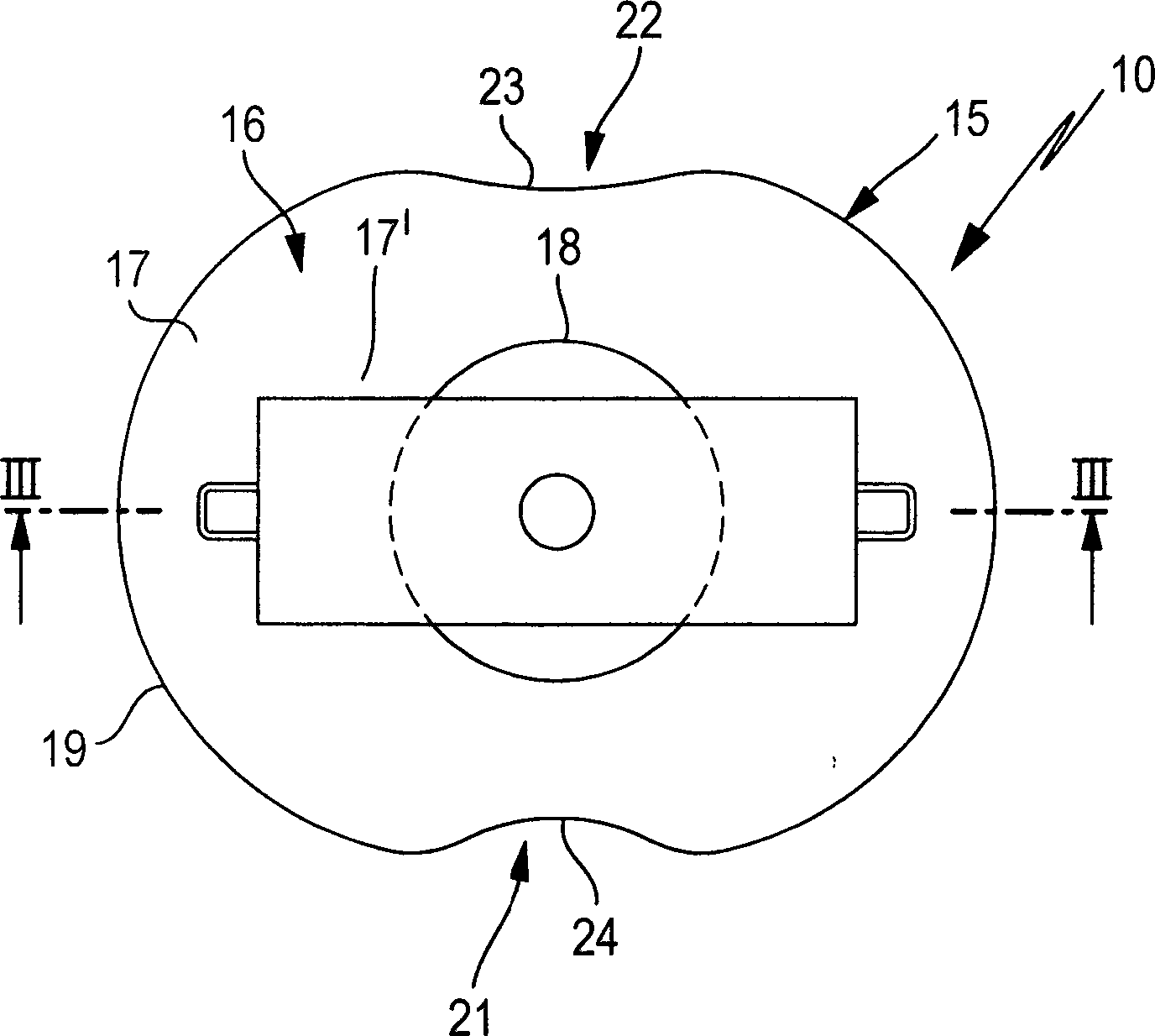
Figure 00000001
Figure 00000001

Description

Die vorliegende Erfindung bezieht sich auf eine Vorrichtung zum schützenden Überdecken einer um ein Abdominalstoma eines Patienten angeordneten und mit einer Stomaaussparung sowie mit zumindest einem Teil eines Stomabeutels versehenen Stomaplatte nach dem Oberbegriff des Anspruchs 1.The The present invention relates to a protective covering device one arranged around an abdominal stoma of a patient and with a stoma recess and at least a portion of an ostomy pouch provided Stomaplatte according to the preamble of claim 1.

In der WO 1997/016141 A ist ein als haubenförmige Schutzabdeckung ausgebildetes Schutzelement beschrieben, das aus einem starren Material ist und einen konkav gewölbten Innenraum sowie U-förmig randseitige Befestigungselemente aufweist. Diese Schutzabdeckung wird auf eine Stomabandage um deren Stomaaussparung herum U-förmig aufgesetzt, wobei an ihrer offenen Unterseite ausreichend Raum zum Durchtritt des Stomabeutels verbleibt. Diese Schutzabdeckung dient ausschließlich dazu, das Abdominalstoma mit dem befestigten Stomabeutelende vor Stößen und sonstigen Krafteinwirkungen zu schützen. Diese bekannte Schutzabdeckung ist jedoch häufig nicht in der Lage, einen Prolaps (Vorfall) bzw. ein Heraustreten oder auch Vorwölben des Darms aus dem Abdominalstoma eines Patienten zu begrenzen oder gar zu verhindern. Zum einen lässt die bekannte Schutzabdeckung zu viel Raum zwischen ihrer Innenseite und dem Abdominalstoma und ist zum anderen lediglich an drei Außenrandseiten um das Abdominalstoma lose gehalten.In the WO 1997/016141 A is designed as a hood-shaped protective cover protective element is described, which is made of a rigid material and has a concavely curved interior and U-shaped edge-side fastening elements. This protective cover is placed on a stomabandage around its stoma cutout around U-shaped, leaving at its open bottom sufficient space for the passage of the stoma bag. This protective cover serves exclusively to protect the abdominal stoma with the attached ostomy bag end from shocks and other forces. However, this known protective cover is often unable to limit or even prevent a prolapse (occurrence) or a protrusion or bulging of the intestine from the abdominal stoma of a patient. On the one hand, the known protective cover leaves too much space between its inner side and the abdominal stoma and, on the other hand, is held loose only on three outer margins around the abdominal stoma.

Aufgabe der vorliegenden Erfindung ist es, eine Vorrichtung zum schützenden Überdecken einer Stomaplatte zu schaffen, mit der nicht nur ein mechanischer Schutz gegen Stoß oder dergleichen sondern auch die Möglichkeit gegeben ist, einen Prolaps (parastomale Hernien) bzw. ein Vorwölben oder Ausstülpen des Darms durch den Abdominalstoma einzugrenzen bzw. vollständig zu verhindern sowie zur Prophylaxe einzusetzen.task It is the object of the present invention to provide a protective covering device to create a stoma plate with not just a mechanical one Protection against shock or the like but also the possibility is given, a prolapse (parastomal hernias) or a protrusion or evagination of the intestine by the abdominal stoma or completely prevent and use for prophylaxis.

Zur Lösung dieser Aufgabe sind bei einer Vorrichtung zum schützenden Überdecken einer Stomaplatte der eingangs genannten Art die im Anspruch 1 angegebenen Merkmale vorgesehen.to Solution of this problem are in a device for protective covering a Stomaplatte of the type mentioned in the claim 1 Features provided.

Durch die erfindungsgemäßen Maßnahmen ist erreicht, dass mit Hilfe der als Druckpelotte ausgebildeten Vorrichtung eine enge Überdeckung der Stomaplatte derart möglich ist, dass in unmittelbarer Nachbarschaft der Stomaaussparung über den Stomabeutel auf die Stomaplatte Druck ausgeübt werden kann, so dass praktisch kein Freiraum verbleibt, in den sich der an die Bauchdecke angenähte Darm durch die Stomaaussparung vorwölben könnte.By the measures according to the invention are achieved that with the help of trained as Druckpelotte device tight coverage of the stoma plate so possible is that in the immediate vicinity of the stoma recess over the ostomy pouch on the Stoma plate pressure to be exercised can, so that there is virtually no free space in which the intestine sutured to the abdominal wall through the stoma recess could bulge.

In besonders vorteilhafter Weise ist gemäß den Merkmalen des Anspruchs 2 mindestens ein Andrückwulst vorgesehen, mit dem unmittelbar auf die Stomaplatte im unmittelbaren Umgebungsbereich der Stomaaussparung Druck ausgeübt werden kann. Dabei sind zweckmäßigerweise die Merkmale nach Anspruch 3 vorgesehen.In is particularly advantageous manner according to the features of claim 2, at least one Andrückwulst provided with the directly on the stoma plate in the immediate vicinity of the Stoma recess pressure can be exerted. There are expediently the features according to claim 3 intended.

Um dem Stomabeutel bzw. dessen Ansatz an der Stomaplatte dennoch eine ausreichende Ausdehnungs- bzw. Öffnungsmöglichkeit zu geben, sind die Merkmale nach Anspruch 4 vorgesehen.Around the ostomy pouch or its approach to the stoma plate nevertheless a sufficient expansion or opening possibility to give the features of claim 4 are provided.

Eine weitere vorteilhafte Ausgestaltung des mindestens einen Andrückwulstes ergibt sich aus den Merkmalen des Anspruchs 5 und/oder 6, wonach die Ausgestaltung des bzw. der Andrückwulste entsprechend der Ausgestaltung einer vorzugsweise zweiteiligen Stomaplatte gegeben ist.A further advantageous embodiment of the at least one Andrückwulstes arises from the features of claim 5 and / or 6, after which the Design of the or the Andrückwulste according to the Design of a preferably two-piece Stoma plate given is.

Mit den Merkmalen nach Anspruch 7 ist eine sehr enge, vorzugsweise formschlüssige Verbindung der Druckpelotte mit bzw. an einem üblicherweise vorhandenen Ringteil einer zweiteiligen Stomaplatte gegeben. Dabei können die Merkmale nach Anspruch 8 vorgesehen sein.With The features of claim 7 is a very close, preferably positive Connection of the pressure pad with or on a usually existing Ring part of a two-piece Stoma plate given. It can the features may be provided according to claim 8.

Mit den Merkmalen nach Anspruch 9 bleibt randseitig oder innerhalb der Druckpelotte Raum für ein am Stomabeutel vorgesehenes Gasfilter.With The features of claim 9 remains at the edge or within the Pressure pad Room for a gas filter provided on the stoma bag.

Mit den Merkmalen nach einem oder mehreren der Ansprüche 10 bis 12 ist eine einfache Herstellung einer einstückig vorgesehenen Druckpelotte gegeben, wobei gleichzeitig die Möglichkeit besteht, das Material der Druckpelotte entsprechend in deren unterschiedlichen Beanspruchungen ausgesetzten Bereiche mit unterschiedlichen Shore-Härten zu versehen. Beispielsweise sind die Andrückwulste sehr weich ausgebildet, um einen nachgiebigen und damit vom Patienten nur wenig spürbaren Druck auf die Stomaplatte ausüben zu können, während die Außenseite der Formbeständigkeit wegen und wegen möglicher mechanischer Beanspruchungen aus Material größer Shore-Härte besteht.With the features according to one or more of claims 10 to 12 is a simple production of an integrally provided Pressure pad given, while the possibility exists, the material of the pressure pad according to their different Stress-exposed areas with different Shore hardnesses to provide. For example, the Andrückwulste are very soft designed to be a yielding and therefore little from the patient to exert noticeable pressure on the stoma plate can, while the outside of the dimensional stability because of and because of possible mechanical stresses Made of material greater Shore hardness.

Weitere vorteilhafte Ausgestaltungen der Druckpelotte ergeben sich aus den Merkmalen eines oder mehrerer der Ansprüche 13 bis 16. Hiermit kann die Druckpelotte in einfacher Weise derart um den Körper des Patienten gebracht werden, dass unmittelbarer Druck auf die Stomaplatte ausgeübt werden kann, was entweder unmittelbar oder mittelbar über eine Stomabandage erfolgen kann.Further advantageous embodiments of the Druckpelotte resulting from the Features of one or more of claims 13 to 16. This allows the Druckpelotte in such a simple way to the body be brought to the patient that immediate pressure on the patient Stoma plate can be exercised, either directly or indirectly via a stomabandage can take place.

Die vorliegende Erfindung bezieht sich ferner auf eine Stomabandage mit einer Vorrichtung nach Anspruch 1 und ggf. mindestens einem der folgenden Ansprüche. Dabei ergibt sich eine vorteilhafte Ausgestaltung nach den Merkmalen des Anspruchs 18.The The present invention further relates to a stoma bandage with a device according to claim 1 and possibly at least one the following claims. This results in an advantageous Embodiment according to the features of claim 18.

Weitere Einzelheiten der Erfindung sind der folgenden Beschreibung zu entnehmen, in der die Erfindung anhand des in der Zeichnung dargestellten Ausführungsbeispieles näher beschrieben und erläutert ist. Es zeigen:Further details of the invention will be apparent from the following description in which the Er invention described in more detail with reference to the embodiment shown in the drawing and explained. Show it:

1 in Außenansicht eine als Druckpelotte ausgebildete Schutzelement gemäß einem bevorzugten Ausführungsbeispiel vorliegender Erfindung, 1 in external view a protective element designed as a pressure pad according to a preferred exemplary embodiment of the present invention,

2 eine Innenansicht der Druckpelotte nach 1, 2 an inside view of the pressure pad after 1 .

3 einen Schnitt längs der Linie III-III der 1, 3 a section along the line III-III of 1 .

4 in Draufsicht eine zweiteilige Stomaplatte mit lösbar angebrachtem Stomabeutel und 4 in plan view, a two-piece Stoma plate with releasably attached stoma bag and

5 einen Schnitt längs der Linie V-V der 4 in aufgesetztem jedoch noch nicht aufgedrücktem Zustand der Druckpelotte. 5 a section along the line VV of 4 in an attached but not yet pressed state of the pressure pad.

Die in der Zeichnung gemäß einem bevorzugten Ausführungsbeispiel dargestellte Vorrichtung 10 dient zum schützenden Überdecken einer um ein Abdominalstoma eines Patienten angeordneten und mit einer Stomaaussparung 12 sowie mit einem Stomabeutel 13 oder zumindest einem Teil davon versehenen Stomaplatte 11. Die Vorrichtung 10 wird im Folgenden auch als Schutzelement bezeichnet.The apparatus shown in the drawing according to a preferred embodiment 10 serves to protectively cover one around a patient's abdominal stoma and with a stoma cutout 12 as well as with an ostomy bag 13 or at least part of it provided stoma plate 11 , The device 10 is also referred to below as a protective element.

Das Schutzelement 10 besteht im Wesentlichen aus einer Druckpelotte 15, die einstückig aus einem Kunststoff, nämlich einem medizinisch reinen Silikon vorzugsweise in einer Gießform hergestellt ist. Dabei werden medizinisch reine Silikone in unterschiedlicher Shore-Härte vorzugsweise von 0 bis 35 verwendet. Welche Shore-Härte für welchen Bestandteil der Druckpelotte 15 verwendet wird, richtet sich nach den Beanspruchungsnotwendigkeiten, was später beschrieben werden wird. Dabei ist die Druckpelotte 15 anatomisch gearbeitet und an den Abdominalstoma eines Patienten sowie dessen dieses umgebenden Körperbereich angepasst.The protective element 10 consists essentially of a pressure pad 15 , which is made in one piece from a plastic, namely a medically pure silicone preferably in a mold. In this case, medically pure silicones in different Shore hardness preferably from 0 to 35 are used. Which Shore hardness for which part of the pressure pad 15 is used, depends on the stress needs, which will be described later. Here is the pressure pad 15 worked anatomically and adapted to the abdominal stoma of a patient and its surrounding body area.

Gemäß den 1 bis 3 ist die Druckpelotte 15 des Schutzelementes 10 im Schnitt gesehen (3) etwa trapezförmig ausgebildet, wobei die Außenseite 16 vom Umfangsrand 19 ausgehend einen rundum leicht konkav ansteigende Außenflächenabschnitt 17 aufweist, die in einem konvexen Abschnitt 17' übergeht und im Scheitel eine kreisrunde ebene Abflachung (Druckfläche) 18 besitzt. In Draufsicht sind an der Außenseite 16 gemäß 1 eine erste Aussparung 21 und eine zweite Aussparung 22 ersichtlich, von denen die erste Aussparung 21 Raum für den Durchtritt des Stomabeutels 13 mit Raum für den Durchtritt von Ausscheidungen im Stomabeutel 13 oder dessen Teil von der Stomaplatte 11 zum Außenbereich des Patienten bildet, während die zweite Aussparung 22, wie noch zu zeigen sein wird, Raum für die zumindest teilweise Unterbringung eines Gasfilters 14 am Stomabeutel 13 gibt.According to the 1 to 3 is the pressure pad 15 of the protective element 10 seen in section ( 3 ) formed approximately trapezoidal, with the outside 16 from the peripheral edge 19 starting from an approximately slightly concave rising outer surface portion 17 that is in a convex section 17 ' goes over and in the apex a circular plane flattening (pressure surface) 18 has. In plan view are on the outside 16 according to 1 a first recess 21 and a second recess 22 visible, of which the first recess 21 Space for the passage of the stoma bag 13 with room for the passage of excretions in the ostomy bag 13 or its part from the stoma plate 11 to the outside of the patient forms, while the second recess 22 as will be shown, room for the at least partial accommodation of a gas filter 14 on the stoma bag 13 gives.

An der gemäß 2 ersichtlichen Innenseite 25 des als Druckpelotte 15 ausgebildeten Schutzelements 10 sind zwei parallele Andrückwulste 26 und 27 vorgesehen, zwischen denen eine konkave Ausnehmung 28 angeordnet ist, die sich zwischen den beiden Aussparungen 21 und 22 erstreckt. Wie auch 2 zeigt, sind die Aussparungen 21 und 22 durch einen Rücksprung 23 bzw. 24 im Umfangsrand 19 der Druckpelotte 15 gebildet. Die konkave Ausbildung der Ausnehmung 28 ergibt sich in Querrichtung zwischen den beiden Andrückwulsten 26 und 27, während in Längserstreckung mittig eine ebene Bodenrinne ergibt, die zur ersten Aussparung 21 weniger und zur zweiten Aussparung 22 stärker ansteigt. Die beiden Andrückwulste 26 und 27 besitzen zur konkaven Ausnehmung 28 hin eine etwa geradlinige Begrenzung 29, während die hierzu abgewandte Begrenzung 31 konvex ausgebildet ist. An diese konvexe Begrenzung 31 grenzt eine Rille 30 an, deren Verlauf entsprechend der konvexen Begrenzung 31 ist und die von einem axialen Ende zum anderen des jeweiligen Andrückwulstes 26, 27 reicht. Die beiden Andrückwulste 26 und 27 überragen die vom Umfangsrand 19 gebildete Ebene. Der Umfangsrand 19 ist durch entsprechendes Zusammenführen von Außenseite 16 und Innenseite 25 zu einer über den Umfang der Druckpelotte 15 verlaufenden und nur durch die Aussparungen 21 und 22 unterbrochenen Andrücklippe 32 gebildet. Die innere Auflagefläche 35 dieser Andrücklippe 32 verläuft, wie sich aus 3 ergibt, vom Umfangsrand 19 ausgehend schräg nach innen zur jeweiligen Rille 30. Der Umfangsrand 19 und damit die äußeren Abmessungen der Pelotte 15 und/oder die Ausnehmung 28 können durch Schneiden und/oder Schleifen bearbeitet und damit individuell anpassbar verändert werden.At the according to 2 visible inside 25 as a pressure pad 15 trained protection element 10 are two parallel Andrückwulste 26 and 27 provided between which a concave recess 28 is arranged, extending between the two recesses 21 and 22 extends. As well as 2 shows are the recesses 21 and 22 by a return 23 respectively. 24 in the peripheral edge 19 the pressure pad 15 educated. The concave configuration of the recess 28 results in the transverse direction between the two Andrückwulsten 26 and 27 , while in the middle of the longitudinal extent results in a flat gutter, the first recess 21 less and to the second recess 22 increases more. The two Andrückwulste 26 and 27 own to the concave recess 28 towards a roughly rectilinear boundary 29 while the boundary facing away from it 31 is convex. At this convex boundary 31 borders a groove 30 whose course corresponds to the convex boundary 31 is and from one axial end to the other of the respective Andrückwulstes 26 . 27 enough. The two Andrückwulste 26 and 27 surmount those from the perimeter 19 educated level. The peripheral edge 19 is by appropriate merging of outside 16 and inside 25 to one over the circumference of the pressure pad 15 running and only through the recesses 21 and 22 interrupted Andrücklippe 32 educated. The inner bearing surface 35 this pressure lip 32 runs, as is 3 results from the peripheral edge 19 starting obliquely inwards to the respective groove 30 , The peripheral edge 19 and thus the outer dimensions of the pad 15 and / or the recess 28 can be edited by cutting and / or grinding and thus individually adjustable.

Wie vorstehend erwähnt, ist die Druckpelotte 15 aus einem medizinisch reinen Silikon hergestellt, das für bestimmte Bereiche der Druckpelotte 15 in unterschiedlicher Shore-Härte eingesetzt wird. Beim Ausführungsbeispiel sind, wie in 3 angedeutet, die Kuppenbereiche 33 und 34 der Andrückwulste 26, 27 aus einem Silikon bspw. l RTV Gel-Silikon mit sehr geringer, vorzugsweise 0-0-30 Shore-Härte versehen, während der übrige Bereich insbesondere der der Außenfläche 17 der anatomisch geformten und elastischen Druckpelotte 15 aus einem Silikon, l bspw. HTV, mit größerer, vorzugsweise A 35 Shore-Härte gestaltet ist. Auch die Andrücklippe 32 kann aus Silikon geringerer Shore-Härte gebildet sein.As mentioned above, the pressure pad is 15 Made from a medically pure silicone, designed for specific areas of the pressure pad 15 used in different Shore hardness. In the embodiment, as in 3 indicated, the crest areas 33 and 34 the Andrückwulste 26 . 27 from a silicone, for example, l RTV gel silicone provided with very low, preferably 0-0-30 Shore hardness, while the rest of the area in particular the outer surface 17 the anatomically shaped and elastic pressure pad 15 made of a silicone, l eg. HTV, with greater, preferably A 35 Shore hardness is designed. Also the Andrücklippe 32 can be made of silicone lower Shore hardness.

Die Andrückwulste 26 und 27 bzw. deren Kuppenbereiche 33, 34 liegen mit ihrem Zenit in derselben Ebene wie die Unterseite der Andrücklippe 32.The Andrückwulste 26 and 27 or their crest areas 33 . 34 lie with their zenith in the same plane as the underside of the Andrücklippe 32 ,

Die 1 und 3 zeigen ferner, dass auf der Abflachung 18 ein Mittel 36 zum Befestigen eines nicht dargestellten Gurtbandes vorgesehen ist, mit welchem Gurtband die Druckpelotte 15 am Körper eines Patienten nicht nur gehalten sondern auch unter Ausübung eines Drucks unmittelbar auf die Stomaplatte 11 befestigt werden kann. Hierzu besitzt das Mittel 36 bspw. eine lösbare Klettverschlussanordnung aus einer Klettscheibe 37 auf der Abflachung 18 der Druckpelotte 15 und einer Gegenklettscheibe 37', die an einem Gurtabschnitt 38 befestigt ist, an dessen beiden Enden jeweils eine Öse 39 gehalten ist, über die das nicht dargestellte um den Patientenkörper spannbare Gurtband, beispielsweise in Form eines Bauchgurtes gehalten werden kann.The 1 and 3 also show that on the flattening 18 a means 36 is provided for securing a webbing, not shown, with which webbing the pressure pad 15 not only held on the body of a patient but also by applying pressure directly to the stoma plate 11 can be attached. For this purpose has the means 36 For example, a detachable hook and loop fastener assembly of a velcro 37 on the flattening 18 the pressure pad 15 and a counter-sling 37 ' attached to a belt section 38 is attached, at its two ends in each case an eyelet 39 is held, via which the webbing, not shown, can be held around the patient's body, for example in the form of a waist belt.

Damit ist das Schutzelement 10 unmittelbar am Körper eines Patienten derart befestigbar, dass die Druckpelotte 15 auf die Stomaplatte 11 Druck ausüben kann.This is the protective element 10 directly attachable to the body of a patient so that the pressure pad 15 on the stomal plate 11 Can exert pressure.

Die 4 und 5 zeigen eine entsprechende Anordnung. Hieraus ist ersichtlich, dass die Stomaplatte 11 zweiteilig ist, nämlich aus einem körperseitigen Teil 41 und einem druckpelottenseitigen Teil 42 aufgebaut ist. Der körperseitige Teil 41 der Stomaplatte 11 besitzt ein Gewebeteil, auf dessen Rückseite eine hautgerechte Klebeschicht 44 angebracht ist, die um das Abdominalstoma auf dem betreffenden Körperbereich des Patienten aufgeklebt werden kann. Die Vorderseite des Gewebeteils 43 ist mit einer biegsamen Kunststoffscheibe 46 bestückt, die wie das Gewebeteil 43 die mittige Stomaaussparung 12 aufweist. Auf der Kunststoffscheibe 46 ist ein elastischer Verbindungsring 47 angebracht.The 4 and 5 show a corresponding arrangement. It can be seen that the stoma plate 11 is two-part, namely from a bodyside part 41 and a pressure pad side part 42 is constructed. The bodyside part 41 the stomal plate 11 has a fabric part, on the back of a skin-friendly adhesive layer 44 is attached, which can be glued to the abdominal stoma on the affected body region of the patient. The front of the fabric part 43 is with a flexible plastic disc 46 fitted, like the fabric part 43 the central stoma recess 12 having. On the plastic disc 46 is an elastic connecting ring 47 appropriate.

Das druckpelottenseitige Teil 42 besitzt einen elastischen Gegenverbindungsring 48 in dessen hinterschnittener Ringnut 49 der entsprechend hinterschnittene Verbindungsring 47 des körperseitigen Teils 41 lösbar verrastbar bzw. einklipsbar ist. Am Gegenverbindungsring 48 ist der Stomabeutel 13 mit einem hier inneren Wandbereich 51 befestigt, der eine Ausnehmung in der Größe des Gegenverbindungsrings 48 besitzt. Dadurch ergibt sich eine Verbindung zwischen Abdominalstoma bzw. Stomaaussparung 12 und dem Stomabeutel 13. Der hier äußere Wandbereich 52 besitzt oberhalb des Gegenverbindungsrings 48 das Gasfilter 14. Beim dargestellten Ausführungsbeispiel der 4 ist vom Stomabeutel 13 lediglich ein Befestigungsteil dargestellt, an den der eigentliche Stomabeutel 13 ansetzbar ist. Es versteht sich, dass es auch möglich ist, den gesamten Stomabeutel 13 unmittelbar mit dem Gegenverbindungsring 48 zu versehen.The pressure pad side part 42 has an elastic counter-connecting ring 48 in its undercut ring groove 49 the corresponding undercut connecting ring 47 the bodyside part 41 is releasably latched or clipped. At the mating connection ring 48 is the stoma bag 13 with an inner wall area 51 attached, the one recess in the size of the mating link 48 has. This results in a connection between abdominal stoma or stoma recess 12 and the stoma bag 13 , The outer wall area here 52 owns above the mating ring 48 the gas filter 14 , In the illustrated embodiment of the 4 is from the stoma bag 13 only a fastener shown, to which the actual ostomy bag 13 can be attached. It is understood that it is also possible to use the whole ostomy bag 13 directly with the mating ring 48 to provide.

5 zeigt die Anordnung der Druckpelotte 15 bzw. der Schutzabdeckung 10 auf der Stomaplatte 11 unter Zwischenfügen des Stomabeutels 13, wobei die Darstellung nach 5 den lediglich lose aufgelegten Zustand zeigt, bei dem die Andrückwulste 26 und 27 auf dem äußeren Wandbereich 52 des Stomabeutels 13 aufliegen. Wird nun gemäß Pfeil D senkrecht auf die Druckpelotte 15 Druck ausgeübt, beispielsweise dadurch, dass der nicht dargestellte Bauchgurt gespannt wird, bewegt sich die Druckpelotte 15 gegen die Stomaplatte 11, auf die ein Gegendruck durch den (hier angedeuteten) betreffenden Körperbereich 55 des Patienten ausgeübt wird. Mit anderen Worten, die Andrückwulste 26 und 27 bewegen die Wandungsbereiche 51 und 52 des Stomabeutels 13 in Richtung des körperseitigen Teils 41 der Stomaplatte 11, wodurch sich auch die beiden Rillen 30 in dieselbe Richtung bewegen, so dass die Rillen 30 etwa formschlüssig über und um den mit dem Verbindungsring 47 verklipsten Gegenverbindungsring 48 greifen. Auf diese Weise wird über die Andrückwulste 26 und 27, die aufgrund der sehr geringen Shore-Härte eine sehr weiche Elastizität besitzen, ein sanfter Vorspanndruck auf die Stomaplatte 11 ausgeübt. Die Andrückwulste 26 und 27 drücken auf die Stomaplatte 11 in unmittelbarer Nachbarschaft bzw. Umgebung der Stomaaussparung 12 innerhalb der Verbindungsringe 47, 48, so dass eine zusätzliche Fixierung der Stomaplatte 11 und deren Aussparung 12 im inneren Bereich erreicht ist. Die radial wirkende formschlussartige Anordnung von Rillen 30 und Gegenverbindungsring 48 verhindern ein Abrutschen der Druckpelotte 15 insbesondere bei sich füllendem Stomabeutel 13. Gleichzeitig liegt die Andrücklippe 32 nahezu rundum und mit ihrer genannten Anlagefläche 35 im Wesentlichen vollflächig auf der Stomaplatte 11 um die Verbindungsringe 47, 48. 5 shows the arrangement of the pressure pad 15 or the protective cover 10 on the stoma plate 11 with the stoma bag inserted 13 , where the representation after 5 shows the only loosely applied state in which the Andrückwulste 26 and 27 on the outer wall area 52 the stoma bag 13 rest. Now according to arrow D perpendicular to the pressure pad 15 Pressure exerted, for example, by the fact that the waist belt, not shown, is stretched, moves the pressure pad 15 against the stoma plate 11 on which a back pressure by the (here indicated) concerned body area 55 the patient is exercised. In other words, the Andrückwulste 26 and 27 move the wall areas 51 and 52 the stoma bag 13 in the direction of the bodyside part 41 the stomal plate 11 , which also causes the two grooves 30 move in the same direction, leaving the grooves 30 about form-fitting over and around with the connecting ring 47 clipped mating connection ring 48 to grab. This way is about the Andrückwulste 26 and 27 , which due to the very low Shore hardness have a very soft elasticity, a gentle biasing pressure on the stoma plate 11 exercised. The Andrückwulste 26 and 27 press on the stoma plate 11 in the immediate vicinity or environment of the stoma recess 12 inside the connecting rings 47 . 48 , so that additional fixation of the stoma plate 11 and their recess 12 is reached in the inner area. The radially acting form-locking arrangement of grooves 30 and counter link ring 48 prevent the pressure pad from slipping off 15 especially with filling stomabeutel 13 , At the same time lies the Andrücklippe 32 almost all around and with their mentioned contact surface 35 essentially full surface on the stoma plate 11 around the connecting rings 47 . 48 ,

Wenn auch beim dargestellten Ausführungsbeispiel davon ausgegangen wird, dass das Schutzelement 10 bzw. die Druckpelotte 15 unmittelbar und allein um den Körperbereich eines Patienten gebracht und unter Aufwendung eines Druckes auf die Stomaplatte 11 fixiert wird, versteht es sich, dass ein derartiges Schutzelement 10 auch in Verbindung mit einer nicht dargestellten Stomabandage verwendet werden kann. Hierzu wird die Druckpelotte 15 in den Bereich einer Aussparung der Stomabandage gebracht und mit Hilfe bspw. einer Klappe oder eines spannbaren Gurtelementes an der Stomabandage auf die Stomaplatte 11 in oben beschriebener Weise gedrückt.Although in the illustrated embodiment it is assumed that the protective element 10 or the pressure pad 15 brought directly and alone around the body area of a patient and applying a pressure on the stoma plate 11 is fixed, it is understood that such a protective element 10 can also be used in conjunction with a stoma bandage, not shown. This is the pressure pad 15 placed in the area of a recess of the stomabandage and with the aid of, for example, a flap or a tensionable belt element on the stomabandage on the stoma plate 11 pressed in the manner described above.

ZITATE ENTHALTEN IN DER BESCHREIBUNGQUOTES INCLUDE IN THE DESCRIPTION

Diese Liste der vom Anmelder aufgeführten Dokumente wurde automatisiert erzeugt und ist ausschließlich zur besseren Information des Lesers aufgenommen. Die Liste ist nicht Bestandteil der deutschen Patent- bzw. Gebrauchsmusteranmeldung. Das DPMA übernimmt keinerlei Haftung für etwaige Fehler oder Auslassungen.This list The documents listed by the applicant have been automated generated and is solely for better information recorded by the reader. The list is not part of the German Patent or utility model application. The DPMA takes over no liability for any errors or omissions.

Zitierte PatentliteraturCited patent literature

  • - WO 1997/016141 A [0002] WO 1997/016141 A [0002]

Claims (18)

Vorrichtung (10) zum schützenden Überdecken einer um ein Abdominalstoma eines Patienten angeordneten und mit einer Stomaaussparung (12) sowie mit zumindest einem Teil eines Stomabeutels (13) versehenen Stomaplatte (11), mit einer teilumfangsseitigen Auflagefläche (35), die von einer Aussparung (21) für den Durchtritt des Stomabeutels (13) unterbrochen ist, dadurch gekennzeichnet, dass die Vorrichtung eine auf die Stomaplatte (11) wirkende, innenseitig anatomisch geformte Druckpelotte (15) aus elastischem Material aufweist.Contraption ( 10 ) for the protective covering of a patient around an abdominal stoma of a patient and with a stoma ( 12 ) and at least part of an ostomy pouch ( 13 ) provided stoma plate ( 11 ), with a partial circumferential contact surface ( 35 ), which are separated by a recess ( 21 ) for the passage of the ostomy pouch ( 13 ) is interrupted, characterized in that the device a on the stoma plate ( 11 ) acting, inside anatomically shaped pressure pad ( 15 ) made of elastic material. Vorrichtung nach Anspruch 1, dadurch gekennzeichnet, dass die Druckpelotte (15) radial innenseitig zur radial äußeren Auflagefläche (35) mindestens einen Andrückwulst (26, 27) aufweist.Apparatus according to claim 1, characterized in that the pressure pad ( 15 ) radially inward to the radially outer bearing surface ( 35 ) at least one Andrückwulst ( 26 . 27 ) having. Vorrichtung nach Anspruch 2, dadurch gekennzeichnet, dass der mindestens eine Andrückwulst (26, 27) über die Ebene der radial äußeren Auflagefläche (35) vorsteht.Apparatus according to claim 2, characterized in that the at least one Andrückwulst ( 26 . 27 ) over the plane of the radially outer bearing surface ( 35 ) protrudes. Vorrichtung nach Anspruch 2 oder 3, dadurch gekennzeichnet, dass innerhalb des mindestens einen Andrückwulstes (26, 27) eine Ausnehmung (28) vorgesehen ist.Apparatus according to claim 2 or 3, characterized in that within the at least one Andrückwulstes ( 26 . 27 ) a recess ( 28 ) is provided. Vorrichtung nach mindestens einem der Ansprüche 2 bis 4, dadurch gekennzeichnet, dass zwei parallele Andrückwulste (26, 27) vorgesehen sind, zwischen denen die Ausnehmung (28) axial verläuft und in die Aussparung (21) der äußeren Auflagefläche (35) mündet.Device according to at least one of claims 2 to 4, characterized in that two parallel Andrückwulste ( 26 . 27 ) are provided, between which the recess ( 28 ) axially and in the recess ( 21 ) of the outer bearing surface ( 35 ) opens. Vorrichtung nach Anspruch 5, dadurch gekennzeichnet, dass die beiden Andrückwulste (26, 27) eine innere geradlinige und eine äußere vorzugsweise kreisförmig konvex gebogene Begrenzung (29, 31) aufweisen.Apparatus according to claim 5, characterized in that the two Andrückwulste ( 26 . 27 ) an inner rectilinear and an outer preferably circular convex curved boundary ( 29 . 31 ) exhibit. Vorrichtung nach mindestens einem der Ansprüche 2 bis 6, dadurch gekennzeichnet, dass zwischen dem oder den Andrückwulsten (26, 27) und der radial äußeren Auflagefläche (35) eine Rille (30) verläuft.Device according to at least one of claims 2 to 6, characterized in that between the or the Andrückwulsten ( 26 . 27 ) and the radially outer bearing surface ( 35 ) a groove ( 30 ) runs. Vorrichtung nach Anspruch 7, dadurch gekennzeichnet, dass die Rille (30) der äußeren konvex gebogenen Begrenzung (31) folgend verläuft.Device according to claim 7, characterized in that the groove ( 30 ) of the outer convexly curved boundary ( 31 ) follows. Vorrichtung nach mindestens einem der vorhergehenden Ansprüche, dadurch gekennzeichnet, dass die radial äußeren Auflagefläche (35) von einer weiteren Ausnehmung (22), die der ersten Ausnehmung (21) vorzugsweise diametral gegenüberliegt, unterbrochen ist.Device according to at least one of the preceding claims, characterized in that the radially outer bearing surface ( 35 ) of a further recess ( 22 ), the first recess ( 21 ) is preferably diametrically opposite, is interrupted. Vorrichtung nach mindestens einem der vorhergehenden Ansprüche, dadurch gekennzeichnet, dass die Druckpelotte (15) aus medizinisch reinem Silikon gefertigt ist.Device according to at least one of the preceding claims, characterized in that the pressure pad ( 15 ) is made of medically pure silicone. Vorrichtung nach Anspruch 10, dadurch gekennzeichnet, dass die Druckpelotte (15) einstückig aus Silikon unterschiedlicher Shore-Härte hergestellt ist.Apparatus according to claim 10, characterized in that the pressure pad ( 15 ) is made in one piece from silicone of different Shore hardness. Vorrichtung nach mindestens einem der Ansprüche 2 bis 6 und dem Anspruch 11, dadurch gekennzeichnet, dass der oder die Andrückwulste (26, 27) aus Silikon sehr geringer, vorzugsweise 0-0-30 Shore-Härte besteht bzw. bestehen.Device according to at least one of claims 2 to 6 and claim 11, characterized in that the or the Andrückwulste ( 26 . 27 ) made of silicone very low, preferably 0-0-30 Shore hardness consists or exist. Vorrichtung nach mindestens einem der vorhergehenden Ansprüche, dadurch gekennzeichnet, dass die Druckpelotte (15) an ihrer der Innenseite (25) abgewandten Außenseite (16) mit einer Druckfläche (18) versehen ist.Device according to at least one of the preceding claims, characterized in that the pressure pad ( 15 ) on its inside ( 25 ) facing away from outside ( 16 ) with a printing surface ( 18 ) is provided. Vorrichtung nach Anspruch 13, dadurch gekennzeichnet, dass die Druckfläche (18) im Zenit der im Schnitt trapezartig ausgebildeten Druckpelotte (15) angeordnet ist.Apparatus according to claim 13, characterized in that the pressure surface ( 18 ) in the zenith of the sectional trapezoidal pressure pad ( 15 ) is arranged. Vorrichtung nach Anspruch 13 oder 14, dadurch gekennzeichnet, dass die Druckfläche (18) mit einem Mittel (36) zur Befestigung eines Gurtbandes versehen ist.Apparatus according to claim 13 or 14, characterized in that the pressure surface ( 18 ) with a means ( 36 ) is provided for fastening a webbing. Vorrichtung nach Anspruch 15, dadurch gekennzeichnet, dass das Mittel (36) zur Befestigung eines Gurtbandes durch einen mit Ösen (39) versehenen Gurtabschnitt (38), der auf der Druckfläche (18) lösbar fixierbar ist, gebildet ist.Device according to claim 15, characterized in that the means ( 36 ) for attaching a webbing through one with eyelets ( 39 ) provided belt section ( 38 ), on the printing surface ( 18 ) is releasably fixable, is formed. Stomabandange mit einer Vorrichtung nach Anspruch 1 und gegebenenfalls nach mindestens einem der folgenden Ansprüche.Stomach bandage with a device according to claim 1 and optionally according to at least one of the following claims. Stomabandage nach Anspruch 17, dadurch gekennzeichnet, dass in einer Stomaausnehmung der Stomabandage die Druckpelotte (15) aufgenommen und von einem an der Stomabandage befestigten oder befestigbaren Gurtelement druckbeaufschlagt gehalten ist.Stomabandage according to claim 17, characterized in that in a Stomaausnehmung the Stomabandage the Druckpelotte ( 15 ) is received and pressurized by a fastened to the stoma abutment or fastened belt member.
DE202009004104U 2009-03-16 2009-03-16 Protective element for abdominal stoma Expired - Lifetime DE202009004104U1 (en)

Priority Applications (1)

Application Number Priority Date Filing Date Title
DE202009004104U DE202009004104U1 (en) 2009-03-16 2009-03-16 Protective element for abdominal stoma

Applications Claiming Priority (1)

Application Number Priority Date Filing Date Title
DE202009004104U DE202009004104U1 (en) 2009-03-16 2009-03-16 Protective element for abdominal stoma

Publications (1)

Publication Number Publication Date
DE202009004104U1 true DE202009004104U1 (en) 2010-08-12

Family

ID=42558238

Family Applications (1)

Application Number Title Priority Date Filing Date
DE202009004104U Expired - Lifetime DE202009004104U1 (en) 2009-03-16 2009-03-16 Protective element for abdominal stoma

Country Status (1)

Country Link
DE (1) DE202009004104U1 (en)

Citations (6)

* Cited by examiner, † Cited by third party
Publication number Priority date Publication date Assignee Title
FR47048E (en) * 1936-02-06 1936-11-30 Improvements to artificial anus bags
US5125917A (en) * 1991-01-04 1992-06-30 William Whealin Ostomy appliances
WO1997016141A1 (en) 1995-11-02 1997-05-09 Desert Shield Trust Ostomy support belt
DE19900611C1 (en) * 1999-01-11 2000-07-06 Hartmut Biesenbach Device for covering an artificial intestine exit, in particular, for persons with prolapse problems comprises a central element which is provided with a depression for limited intestine movements
DE69708946T2 (en) * 1996-02-14 2002-04-25 Hollister Inc., Libertyville One-piece ostomy device with bag, support plate and integrated convex pressure ring
WO2008149887A1 (en) * 2007-06-06 2008-12-11 Women's Medical Research, Inc. Device for preventing and treating pelvic organ prolapse

Patent Citations (6)

* Cited by examiner, † Cited by third party
Publication number Priority date Publication date Assignee Title
FR47048E (en) * 1936-02-06 1936-11-30 Improvements to artificial anus bags
US5125917A (en) * 1991-01-04 1992-06-30 William Whealin Ostomy appliances
WO1997016141A1 (en) 1995-11-02 1997-05-09 Desert Shield Trust Ostomy support belt
DE69708946T2 (en) * 1996-02-14 2002-04-25 Hollister Inc., Libertyville One-piece ostomy device with bag, support plate and integrated convex pressure ring
DE19900611C1 (en) * 1999-01-11 2000-07-06 Hartmut Biesenbach Device for covering an artificial intestine exit, in particular, for persons with prolapse problems comprises a central element which is provided with a depression for limited intestine movements
WO2008149887A1 (en) * 2007-06-06 2008-12-11 Women's Medical Research, Inc. Device for preventing and treating pelvic organ prolapse

Similar Documents

Publication Publication Date Title
DE69918458T2 (en) ostomy appliance
DE10142491B4 (en) Sealing arrangement with lips for a prosthetic socket
DE60104415T2 (en) OSTOMETRY DISK WITH FLEXIBLE FLANGE
EP3708112B1 (en) Film tensioning element
DE20113445U1 (en) Device for deriving uncontrolled urination in male people
DE1881215U (en) FOOTBALL RAIL.
DE102014104737A1 (en) Ostomy bag with drain valve and method for making an ostomy pouch
EP3150179B1 (en) Cuff for penis extension devices
DE102013221225A1 (en) Fastening device for fastening a measuring pressure sensor, in particular tire pressure sensor
EP2285316B1 (en) Limb stump receiving sleeve comprising an integrated locking device for a sealing element
DE69817632T2 (en) Ostomy coupling
EP2354041B1 (en) Refuse receptacle with means for fixing a trash bag
DE202009004104U1 (en) Protective element for abdominal stoma
DE102014018814A1 (en) Ostomy device and spacer for an ostomy device
DE102017113443A1 (en) Emptying ostomy bag
DE102012203860A1 (en) hybrid diaper
DE202014009977U1 (en) Ostomy device and spacer for an ostomy device
DE202011107040U1 (en) Orthopedic support device with one-hand operation
DE102016113705B3 (en) Sleep mask
DE102010007113A1 (en) Fabric cover for prosthetic body parts
DE202017101866U1 (en) Cuff for orthotic treatment
DE2260692C3 (en) Pad with waist belt for artificial exit
AT386525B (en) CLAMPING DEVICE FOR SECURING THE CONNECTION OF A HOSE, e.g. CATHETER OR INFUSION LINE, WITH A COUPLING PART
CH372792A (en) Faecal container for artificial anus
DE29900295U1 (en) Device for covering an artificial intestinal exit, in particular for intestinal exit carriers with prolapse problems

Legal Events

Date Code Title Description
R163 Identified publications notified
R207 Utility model specification

Effective date: 20100916

R150 Term of protection extended to 6 years

Effective date: 20120531

R151 Term of protection extended to 8 years
R152 Term of protection extended to 10 years
R071 Expiry of right