DE112023002506T5 - Ball screw device - Google Patents
Ball screw device Download PDFInfo
- Publication number
- DE112023002506T5 DE112023002506T5 DE112023002506.1T DE112023002506T DE112023002506T5 DE 112023002506 T5 DE112023002506 T5 DE 112023002506T5 DE 112023002506 T DE112023002506 T DE 112023002506T DE 112023002506 T5 DE112023002506 T5 DE 112023002506T5
- Authority
- DE
- Germany
- Prior art keywords
- groove
- nut member
- lead screw
- hole
- balls
- Prior art date
- Legal status (The legal status is an assumption and is not a legal conclusion. Google has not performed a legal analysis and makes no representation as to the accuracy of the status listed.)
- Pending
Links
Images


Classifications
-
- F—MECHANICAL ENGINEERING; LIGHTING; HEATING; WEAPONS; BLASTING
- F16—ENGINEERING ELEMENTS AND UNITS; GENERAL MEASURES FOR PRODUCING AND MAINTAINING EFFECTIVE FUNCTIONING OF MACHINES OR INSTALLATIONS; THERMAL INSULATION IN GENERAL
- F16H—GEARING
- F16H25/00—Gearings comprising primarily only cams, cam-followers and screw-and-nut mechanisms
- F16H25/18—Gearings comprising primarily only cams, cam-followers and screw-and-nut mechanisms for conveying or interconverting oscillating or reciprocating motions
- F16H25/20—Screw mechanisms
- F16H25/22—Screw mechanisms with balls, rollers, or similar members between the co-operating parts; Elements essential to the use of such members
- F16H25/2204—Screw mechanisms with balls, rollers, or similar members between the co-operating parts; Elements essential to the use of such members with balls
-
- F—MECHANICAL ENGINEERING; LIGHTING; HEATING; WEAPONS; BLASTING
- F16—ENGINEERING ELEMENTS AND UNITS; GENERAL MEASURES FOR PRODUCING AND MAINTAINING EFFECTIVE FUNCTIONING OF MACHINES OR INSTALLATIONS; THERMAL INSULATION IN GENERAL
- F16H—GEARING
- F16H25/00—Gearings comprising primarily only cams, cam-followers and screw-and-nut mechanisms
- F16H25/18—Gearings comprising primarily only cams, cam-followers and screw-and-nut mechanisms for conveying or interconverting oscillating or reciprocating motions
- F16H25/20—Screw mechanisms
- F16H25/22—Screw mechanisms with balls, rollers, or similar members between the co-operating parts; Elements essential to the use of such members
- F16H25/2204—Screw mechanisms with balls, rollers, or similar members between the co-operating parts; Elements essential to the use of such members with balls
- F16H25/2214—Screw mechanisms with balls, rollers, or similar members between the co-operating parts; Elements essential to the use of such members with balls with elements for guiding the circulating balls
- F16H25/2223—Cross over deflectors between adjacent thread turns, e.g. S-form deflectors connecting neighbouring threads
-
- F—MECHANICAL ENGINEERING; LIGHTING; HEATING; WEAPONS; BLASTING
- F16—ENGINEERING ELEMENTS AND UNITS; GENERAL MEASURES FOR PRODUCING AND MAINTAINING EFFECTIVE FUNCTIONING OF MACHINES OR INSTALLATIONS; THERMAL INSULATION IN GENERAL
- F16H—GEARING
- F16H25/00—Gearings comprising primarily only cams, cam-followers and screw-and-nut mechanisms
- F16H25/18—Gearings comprising primarily only cams, cam-followers and screw-and-nut mechanisms for conveying or interconverting oscillating or reciprocating motions
- F16H25/20—Screw mechanisms
- F16H25/22—Screw mechanisms with balls, rollers, or similar members between the co-operating parts; Elements essential to the use of such members
-
- F—MECHANICAL ENGINEERING; LIGHTING; HEATING; WEAPONS; BLASTING
- F16—ENGINEERING ELEMENTS AND UNITS; GENERAL MEASURES FOR PRODUCING AND MAINTAINING EFFECTIVE FUNCTIONING OF MACHINES OR INSTALLATIONS; THERMAL INSULATION IN GENERAL
- F16H—GEARING
- F16H25/00—Gearings comprising primarily only cams, cam-followers and screw-and-nut mechanisms
- F16H25/18—Gearings comprising primarily only cams, cam-followers and screw-and-nut mechanisms for conveying or interconverting oscillating or reciprocating motions
- F16H25/20—Screw mechanisms
- F16H25/22—Screw mechanisms with balls, rollers, or similar members between the co-operating parts; Elements essential to the use of such members
- F16H25/2204—Screw mechanisms with balls, rollers, or similar members between the co-operating parts; Elements essential to the use of such members with balls
- F16H25/2214—Screw mechanisms with balls, rollers, or similar members between the co-operating parts; Elements essential to the use of such members with balls with elements for guiding the circulating balls
-
- F—MECHANICAL ENGINEERING; LIGHTING; HEATING; WEAPONS; BLASTING
- F16—ENGINEERING ELEMENTS AND UNITS; GENERAL MEASURES FOR PRODUCING AND MAINTAINING EFFECTIVE FUNCTIONING OF MACHINES OR INSTALLATIONS; THERMAL INSULATION IN GENERAL
- F16H—GEARING
- F16H25/00—Gearings comprising primarily only cams, cam-followers and screw-and-nut mechanisms
- F16H25/18—Gearings comprising primarily only cams, cam-followers and screw-and-nut mechanisms for conveying or interconverting oscillating or reciprocating motions
- F16H25/20—Screw mechanisms
- F16H25/24—Elements essential to such mechanisms, e.g. screws, nuts
Landscapes
- Engineering & Computer Science (AREA)
- General Engineering & Computer Science (AREA)
- Mechanical Engineering (AREA)
- Transmission Devices (AREA)
Abstract
Angegeben wird eine Kugelgewindetriebvorrichtung, die Folgendes umfasst: eine große Anzahl von Kugeln; eine Gewindespindel (110) mit einer Rollnut (111) für die Kugeln, die spiralförmig in einer Außenumfangsfläche der Gewindespindel (110) ausgebildet ist; und ein Mutterelement (120) mit: einem Durchgangsloch, durch das die Gewindespindel (110) eingesetzt werden kann; und eine Vorschubnut (210), die in einer inneren Umfangsfläche (240) des Durchgangslochs ausgebildet ist und es der großen Anzahl von Kugeln ermöglicht, nur einmal um einen Umfang der Gewindespindel (110) zu zirkulieren, wobei das Mutterelement (120) so konfiguriert ist, dass es unter Vermittlung der großen Anzahl von Kugeln mit der Gewindespindel (110) in Gewindeeingriff gebracht wird. Die Vorschubnut (210) umfasst: eine Lastrollnut (121), die einem Teil der Rollnut (111) der Gewindespindel (110) zugewandt ist; und eine Umlaufnut (220), die so ausgebildet ist, dass sie ein Schraubengewinde der Gewindespindel (110) durchquert, um beide Enden der Lastrollnut (121) miteinander zu verbinden. Die Vorschubnut (210) ist so ausgebildet, dass sie an eine Öffnungskante des Durchgangslochs des Mutterelements (120) angrenzt. Ein Neigungsabschnitt (230) ist an einem Winkelabschnitt (310) vorgesehen, an dem sich die innere Umfangsfläche (240) des Durchgangslochs und eine axiale Endfläche des Mutterelements (120), wobei der Neigungsabschnitt (230) durch Ausschneiden des Winkelabschnitts (310) gebildet wird, so dass der Neigungsabschnitt (230) eine ungleichmäßige Breite entlang einer Umfangsrichtung des Durchgangslochs aufweist.Provided is a ball screw device comprising: a large number of balls; a lead screw (110) having a rolling groove (111) for the balls, which is spirally formed in an outer peripheral surface of the lead screw (110); and a nut member (120) having: a through hole through which the lead screw (110) can be inserted; and a feed groove (210) formed in an inner peripheral surface (240) of the through hole and allowing the large number of balls to circulate only once around a circumference of the lead screw (110), wherein the nut member (120) is configured to be threadably engaged with the lead screw (110) through the intermediary of the large number of balls. The feed groove (210) includes: a load rolling groove (121) facing a part of the rolling groove (111) of the lead screw (110); and a circumferential groove (220) formed to traverse a screw thread of the lead screw (110) to connect both ends of the load rolling groove (121) to each other. The feed groove (210) is formed to be adjacent to an opening edge of the through hole of the nut member (120). An inclination portion (230) is provided at an angle portion (310) where the inner peripheral surface (240) of the through hole and an axial end surface of the nut member (120) meet, the inclination portion (230) being formed by cutting out the angle portion (310) so that the inclination portion (230) has an uneven width along a circumferential direction of the through hole.
Description
TECHNISCHES GEBIETTECHNICAL FIELD
Die vorliegende Erfindung bezieht sich auf eine Kugelgewindetriebvorrichtung, bei der ein endloser Kugelumlaufpfad, der einer Runde um den Umfang einer Gewindespindel entspricht, in einem Mutternbauteil ausgebildet ist.The present invention relates to a ball screw device in which an endless ball recirculation path corresponding to one lap around the circumference of a lead screw is formed in a nut member.
TECHNISCHER HINTERGRUNDTECHNICAL BACKGROUND
Ein Kugelgewindetrieb ist ein mechanisches Element, das eine Umwandlung zwischen einer Drehbewegung und einer Linearbewegung durchführen kann und in verschiedenen Werkzeugmaschinen, Fördervorrichtungen, Industrierobotern und dergleichen weit verbreitet ist, um eine von einem Servomotor erzeugte Drehbewegung in eine lineare Bewegung umzuwandeln. Eine solche Kugelgewindetriebvorrichtung umfasst: eine Gewindespindel mit einer spiralförmig ausgebildeten Rollnut; eine Vielzahl von Kugeln, die in der Rollnut rollen; und ein Mutterelement mit einem Durchgangsloch, die das Einführen der Gewindespindel durch das Loch ermöglicht, sowie einen endlosen Umlaufpfad, der das Rollen der Kugeln im endlosen Umlaufpfad ermöglicht. Die Gewindespindel und das Mutterelement sind über eine Vielzahl von Kugeln miteinander in Eingriff. Es sind verschiedene Kugelgewindetriebvorrichtungen bekannt, die sich in der Struktur des endlosen Umlaufpfades unterscheiden. In der Patentschrift 1 ist eine Kugelgewindetriebvorrichtung beschrieben, bei der in einem derartigen Mutterelement eine Vielzahl von Umlaufpfaden ausgebildet ist, wobei jeder Pfad einer Runde um den Umfang der Gewindespindel entspricht.A ball screw is a mechanical element capable of converting between rotary motion and linear motion. It is widely used in various machine tools, conveyors, industrial robots, and the like to convert rotary motion generated by a servo motor into linear motion. Such a ball screw device includes: a lead screw having a spiral rolling groove; a plurality of balls rolling in the rolling groove; and a nut member having a through hole for inserting the lead screw through the hole; and an endless circulation path for allowing the balls to roll in the endless circulation path. The lead screw and the nut member are engaged with each other via a plurality of balls. Various ball screw devices are known, differing in the structure of the endless circulation path.
In der Kugelgewindetriebvorrichtung der Patentschrift 1 ist in einer inneren Umfangsfläche des Durchgangslochs des Mutterelements eine Lastrollnut ausgebildet, die einem Teil der Rollnut der Gewindespindel gegenüberliegt, sowie eine Umlaufnut, die einen Anfangs- und einen Endpunkt der Lastrollnut miteinander verbindet. Die Lastrollnut ist der Rollnut der Gewindespindel zugewandt, um so einen Lastpfad zu bilden, und Kugeln rollen innerhalb des Lastpfads, während sie eine Last zwischen der Gewindespindel und dem Mutterelement tragen. Die Umlaufnut ermöglicht es jeder der Kugeln, die das Ende des Lastpfads erreicht hat, von der Rollnut der Gewindespindel getrennt zu werden, um über ein Schraubengewinde zu gelangen und dann zum Startende des Lastpfads zurückzukehren. Das heißt, die Umlaufnut ermöglicht es jeder der Kugeln, die innerhalb des Lastpfads rollen, um eine einzige Steigung der Rollnut der Gewindespindel zu einer vorherigen Position zurückzukehren. Dementsprechend ist jeder der in dem Mutterelement gebildeten endlosen Umlaufpfade so konfiguriert, dass er einen Kreislauf aufweist, der einer Runde um den Umfang der Gewindespindel entspricht.In the ball screw device of
Bei der Kugelgewindetriebvorrichtung der Patentliteratur 1, wie oben beschrieben, sind die Lastrollnut und die Umlaufnut direkt in der inneren Umfangsfläche des Mutterelements ausgebildet. Insbesondere wird die letztgenannte Umlaufnut durch Schneidarbeiten an der inneren Umfangsfläche des Mutterelements unter Verwendung eines Werkzeugs wie eines Schaftfräsers gebildet. Bei solchen Schneidarbeiten wird das Werkzeug in das Durchgangsloch des Mutterelements aus einer axialen Richtung des Durchgangslochs eingeführt, dann wird mit dem Werkzeug an der inneren Umfangsfläche des Durchgangslochs in einer radialen Richtung geschnitten, und die Tiefe des Schneidens wird gesteuert, um dadurch die Umlaufnut zu bilden.In the ball screw device of
ZITIERLISTECITATION LIST
PATENTLITERATURPATENT LITERATURE
[PTL 1]
OFFENBARUNG DER ERFINDUNGDISCLOSURE OF THE INVENTION
DURCH DIE ERFINDUNG ZU LÖSENDE PROBLEMEPROBLEMS TO BE SOLVED BY THE INVENTION
Wie oben beschrieben, ermöglicht die Umlaufnut, dass jede der Kugeln von der Rollnut der Gewindespindel getrennt wird, um über das Schraubengewinde der Gewindespindel zu laufen. Somit ist die Umlaufnut nicht als ein von der Gewindespindel getrennter Pfad ausgebildet, sondern als ein Pfad, der zur Gewindespindel hin offen ist.As described above, the recirculating groove allows each ball to be separated from the rolling groove of the lead screw and roll over the screw thread of the lead screw. Thus, the recirculating groove is not designed as a path separate from the lead screw, but as a path open to the lead screw.
Dementsprechend besteht die Gefahr, dass die in der Umlaufnut rollenden Kugeln unregelmäßig mit dem Schraubengewinde der Gewindespindel in Kontakt kommen, und daher besteht die Befürchtung, dass die reibungslose Zirkulation der Kugeln innerhalb des endlosen Umlaufpfades behindert werden könnte.Accordingly, there is a risk that the balls rolling in the circulation groove will irregularly come into contact with the screw thread of the lead screw, and therefore there is a fear that the smooth circulation of the balls within the endless circulation path may be hindered.
Wenn man in Betracht zieht, den Kontakt zwischen den in der Umlaufnut rollenden Kugeln und der Gewindespindel so weit wie möglich zu verhindern und ein reibungsloses Bewegen der Kugeln von der Rollnut der Gewindespindel zur Umlaufnut zu ermöglichen, ist es denkbar, dass ein Halteabschnitt an einer Öffnungskante der Umlaufnut entlang einer Bewegungsrichtung der Kugeln vorgesehen ist und eine Öffnungsbreite der Umlaufnut, die zur Gewindespindel hin geöffnet ist, kleiner als ein Durchmesser jeder der Kugeln ist.Considering to prevent the contact between the balls rolling in the revolving groove and the lead screw as much as possible and to enable the balls to move smoothly from the rolling groove of the lead screw to the revolving groove, it is conceivable that a holding portion is provided at an opening edge of the revolving groove along a moving direction of the balls and an opening width of the revolving groove opened to the lead screw is smaller than a diameter of each of the balls.
In diesem Zusammenhang wird in der Patentliteratur 1 das Werkzeug zum Zeitpunkt der Bearbeitung des Mutterelements in das Durchgangsloch des Mutterelements von der axialen Richtung des Durchgangslochs aus eingeführt und das Schneiden wird unter Verwendung des Werkzeugs an der inneren Umfangsfläche des Durchgangslochs des Mutterelements in der radialen Richtung durchgeführt, um dadurch die Umlaufnut zu bilden. Daher war es schwierig, den Halteabschnitt an der Öffnungskante der Umlaufnut zu formen.In this context, in
MITTEL ZUR LÖSUNG DER PROBLEMEMEANS TO SOLVE THE PROBLEMS
Die vorliegende Erfindung wurde im Hinblick auf die oben beschriebenen Probleme gemacht und hat das Ziel, eine Kugelgewindetriebvorrichtung bereitzustellen, die eine gleichmäßige Zirkulation von Kugeln in einem endlosen Umlaufpfad ermöglicht, selbst wenn eine Umlaufnut in einer inneren Umfangsfläche eines Mutterelements durch Schneidarbeiten geformt wird.The present invention has been made in view of the problems described above and has an object to provide a ball screw device that enables smooth circulation of balls in an endless circulation path even when a circulation groove is formed in an inner peripheral surface of a nut member by cutting work.
Das heißt, gemäß der vorliegenden Erfindung wird eine Kugelgewindetriebvorrichtung bereitgestellt, die Folgendes umfasst: eine große Anzahl von Kugeln; eine Gewindespindel mit einer Rollnut für die Kugeln, die spiralförmig in einer äußeren Umfangsfläche der Gewindespindel ausgebildet ist; und ein Mutterelement mit: einem Durchgangsloch, durch das die Gewindespindel eingeführt werden kann; und einer Vorschubnut , die in einer inneren Umfangsfläche des Durchgangslochs ausgebildet ist und es der großen Anzahl von Kugeln ermöglicht, nur eine einzige Runde um einen Umfang der Gewindespindel zu zirkulieren, wobei das Mutterelement eine darin spiralförmig ausgebildete Lastrollnut aufweist, die der Rollnut zugewandt ist, und so konfiguriert ist, dass sie über die Vermittlung der großen Anzahl von Kugeln, die in der Vorschubnut rollen, mit der Gewindespindel in Gewindeeingriff gebracht wird. Die Vorschubnut des Mutterelements umfasst: die Lastrollnut, die einem Teil der Rollnut der Gewindespindel zugewandt ist; und eine Umlaufnut, die so geformt ist, dass sie ein Schraubengewinde der Gewindespindel durchquert, um beide Enden der Lastrollnut miteinander zu verbinden. Die Vorschubnut ist so geformt, dass sie an eine Öffnungskante des Durchgangslochs des Mutterelements angrenzt. Ein Neigungsabschnitt ist an einem Winkelabschnitt vorgesehen, an dem sich die innere Umfangsfläche des Durchgangslochs und eine axiale Endfläche des Mutterelements schneiden, wobei der Neigungsabschnitt durch Ausschneiden des Winkelabschnitts gebildet wird, so dass der Neigungsabschnitt entlang einer Umfangsrichtung des Durchgangslochs eine ungleichmäßige Breite aufweist.That is, according to the present invention, there is provided a ball screw device comprising: a large number of balls; a lead screw having a rolling groove for the balls spirally formed in an outer peripheral surface of the lead screw; and a nut member having: a through hole through which the lead screw can be inserted; and a feed groove formed in an inner peripheral surface of the through hole and allowing the large number of balls to circulate only a single lap around a circumference of the lead screw, wherein the nut member has a load rolling groove spirally formed therein, facing the rolling groove, and is configured to be threadably engaged with the lead screw through the intermediation of the large number of balls rolling in the feed groove. The feed groove of the nut member includes: the load rolling groove facing a part of the rolling groove of the lead screw; and a circumferential groove formed to traverse a screw thread of the lead screw to connect both ends of the load rolling groove. The feed groove is formed to be adjacent to an opening edge of the through hole of the nut member. A slope portion is provided at an angle portion where the inner peripheral surface of the through hole and an axial end surface of the nut member intersect. The slope portion is formed by cutting out the angle portion so that the slope portion has an uneven width along a circumferential direction of the through hole.
EFFEKTE DER ERFINDUNGEFFECTS OF THE INVENTION
Bei der Kugelgewindetriebvorrichtung der vorliegenden Erfindung ist der Neigungsabschnitt an dem Winkelabschnitt vorgesehen, an dem sich die innere Umfangsfläche des in dem Mutterelement ausgebildeten Durchgangslochs und die axiale Endfläche des Mutterelements schneiden, und der Neigungsabschnitt wird durch Ausschneiden des Winkelabschnitts gebildet, so dass der Neigungsabschnitt die ungleichmäßige Breite entlang der Umfangsrichtung des Durchgangslochs aufweist. Somit ist bei der Kugelgewindetriebvorrichtung zum Zeitpunkt der Schneidarbeiten am Mutterelement ein Einführwinkel eines Schneidwerkzeugs in Bezug auf die innere Umfangsfläche des Durchgangslochs nicht durch einen Abstand der Umlaufnut von der axialen Endfläche begrenzt, und die Schneidarbeiten können zum Ausbilden der Umlaufnut bei jedem geeigneten Einführwinkel gemäß der ungleichmäßigen Breite des Neigungsabschnitts durchgeführt werden. Dadurch kann die Umlaufnut mit ausreichendem Halt versehen werden und somit jede der Kugeln führen, die über das Schraubengewinde laufen soll. Dementsprechend ist es gemäß der Kugelgewindetriebvorrichtung der vorliegenden Erfindung möglich, eine gleichmäßige endlose Zirkulation der rollenden Kugeln zu erreichen, selbst wenn die Umlaufnut in der inneren Umfangsfläche des Mutterelements durch die Schneidarbeit gebildet wird.In the ball screw device of the present invention, the inclined portion is provided at the angled portion where the inner peripheral surface of the through-hole formed in the nut member and the axial end surface of the nut member intersect, and the inclined portion is formed by cutting out the angled portion so that the inclined portion has the uneven width along the circumferential direction of the through-hole. Thus, in the ball screw device, at the time of cutting work on the nut member, an insertion angle of a cutting tool with respect to the inner peripheral surface of the through-hole is not limited by a distance of the circumferential groove from the axial end surface, and the cutting work can be performed to form the circumferential groove at any appropriate insertion angle according to the uneven width of the inclined portion. This allows the circumferential groove to be provided with sufficient support and thus guide each of the balls to be passed over the screw thread. Accordingly, according to the ball screw device of the present invention, it is possible to achieve a smooth endless circulation of the rolling balls even if the circulation groove is formed in the inner peripheral surface of the nut member by the cutting work.
KURZE BESCHREIBUNG DER ZEICHNUNGENBRIEF DESCRIPTION OF THE DRAWINGS
-
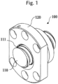
1 ist eine perspektivische Ansicht zur Veranschaulichung einer Kugelgewindetriebvorrichtung gemäß einer Ausführungsform der vorliegenden Erfindung.1 is a perspective view illustrating a ball screw device according to an embodiment of the present invention. -
2 ist eine Schnittansicht zur Veranschaulichung eines Mutterelements in einer Ausführungsform der vorliegenden Erfindung.2 is a sectional view illustrating a nut member in an embodiment of the present invention. -
3 ist eine Schnittansicht zur Veranschaulichung einer Umlaufnut.3 is a sectional view illustrating a circumferential groove. -
4 ist eine perspektivische Ansicht zur Veranschaulichung des Mutterelements in einer Ausführungsform der vorliegenden Erfindung.4 is a perspective view illustrating the nut member in one embodiment of the present invention. -
5 ist eine perspektivische Ansicht zur Veranschaulichung eines Zustands, in dem Schneidarbeiten am Mutterelement durchgeführt werden.5 is a perspective view illustrating a state in which cutting work is performed on the nut member. -
6 ist eine Ansicht zur Veranschaulichung eines Zustands, in dem das Mutterelement in einer Ausführungsform der vorliegenden Erfindung aus einer axialen Richtung betrachtet wird.6 is a view illustrating a state in which the nut member in an embodiment of the present invention is viewed from an axial direction. -
7 ist eine vergrößerte Schnittansicht des Mutterelements in einer Ausführungsform der vorliegenden Erfindung.7 is an enlarged sectional view of the nut member in one embodiment of the present invention. -
8 ist ein Diagramm zur Darstellung einer Beziehung zwischen einer Ausschnittbreite „w“ eines Neigungsabschnitts und einer Umfangsposition θ.8 is a diagram showing a relationship between a cutout width “w” of a slope section and a circumferential position θ. -
9 ist ein Diagramm zur Darstellung einer Beziehung zwischen einer Oberflächentiefe „h“ des Neigungsabschnitts und einer Umfangsposition θ.9 is a diagram showing a relationship between a surface depth “h” of the slope section and a circumferential position θ. -
10 ist ein Diagramm zur Darstellung einer Beziehung zwischen einem Abstand „s“ einer Umlaufnut und einer Umfangsposition θ.10 is a diagram showing a relationship between a distance “s” of a circumferential groove and a circumferential position θ. -
11 ist eine Schnittansicht entlang der Linie III-III von6 .11 is a sectional view along the line III-III of6 . -
12 ist eine Schnittansicht zur Veranschaulichung eines Zustands, in dem die Schneidarbeit am Mutterelement ausgeführt wird.12 is a sectional view illustrating a state in which cutting work is performed on the nut member. -
13 ist eine vergrößerte Schnittansicht zur Veranschaulichung der Umlaufnut zu dem Zeitpunkt, an dem die Schneidarbeit am Mutterelement ausgeführt wurde.13 is an enlarged sectional view illustrating the circumferential groove at the time the cutting work was performed on the nut element. -
14 ist eine perspektivische Ansicht zur Veranschaulichung eines Zustands, in dem die Schneidarbeit am Mutterelement der verwandten Technik ausgeführt wird.14 is a perspective view illustrating a state in which cutting work is performed on the nut member of the related art. -
15 ist eine vergrößerte Schnittansicht zur Veranschaulichung einer Umlaufnut zu dem Zeitpunkt, an dem die Schneidarbeit an dem Mutternelement der verwandten Technik ausgeführt wurde.15 is an enlarged sectional view illustrating a circumferential groove at the time when cutting work was performed on the nut member of the related art.
MODEN ZUR DURCHFÜHRUNG DER ERFINDUNGMODES FOR CARRYING OUT THE INVENTION
Nun wird eine Kugelgewindetriebvorrichtung der vorliegenden Erfindung unter Bezugnahme auf die beigefügten Zeichnungen detailliert beschrieben.Now, a ball screw device of the present invention will be described in detail with reference to the accompanying drawings.
Die Lastrollnut 121 ist spiralförmig ausgebildet, so dass sie einem Teil der Rollnut der Gewindespindel 110 zugewandt ist und eine Länge aufweist, die kleiner ist als eine Umrundung des Umfangs der Gewindespindel. Die Lastrollnut 121 ist der Rollnut 111 der Gewindespindel 110 zugewandt, um dadurch einen Lastweg zu bilden, und die Kugeln rollen innerhalb des Lastwegs, während sie eine Last zwischen der Schraubenwelle und dem Mutterelement tragen.The
Inzwischen ist die Umlaufnut 220 in der inneren Umfangsfläche 240 des Mutterelements 120 so ausgebildet, dass sie mit der Lastrollnut 121 durchgehend ist, und ist als Nut, die tiefer als die Lastrollnut 121 ist, ausgebildet, damit jede der Kugeln von der Rollnut 111 der Gewindespindel 110 getrennt werden kann, um über ein Schraubengewinde der Gewindespindel 110 zu laufen. Das heißt, die Umlaufnut 220 ist so geformt, dass sie das Schraubengewinde der Gewindespindel 110 durchquert, um ein Ende und ein anderes Ende der Lastrollnut 121 miteinander zu verbinden. Wenn die Kugeln von der Lastrollnut 121 in die Umlaufnut 220 eintreten, werden die Kugeln von der Last gelöst, um in einen unbelasteten Zustand gebracht zu werden. Wenn die Kugeln dann von der Umlaufnut 220 in die Lastrollnut 121 eintreten, tragen die Kugeln wieder eine Last. Das heißt, die Umlaufnut 220 ist ein Leerlaufpfad für die Kugeln, und beide Enden des Lastpfads sind über den Leerlaufpfad miteinander verbunden, um so einen endlosen Umlaufpfad zu bilden, der sich einmal um den Umfang der S Gewindespindel 110 erstreckt. Dementsprechend weist das Mutterelement 120 in dieser Ausführungsform zwei Kreisläufe von endlosen Umlaufpfaden für die Kugeln auf.Meanwhile, the circulating
An beiden Enden der Umlaufnut 220 sind Verbindungsabschnitte (nicht dargestellt) vorgesehen, an denen das Passieren und Aufnehmen der Kugeln zwischen der Umlaufnut 220 und der Lastrollnut 121 erfolgen soll. Jeder der Verbindungsabschnitte ist in Bezug auf die Zirkulationsnut 220 leicht geneigt, wodurch die Kugeln, die in der Lastrollnut 121 rollen, von einer Last gelöst werden können und sich die Kugeln auch allmählich von der Rollnut der Gewindespindel 110 trennen können. Dementsprechend kann jede der Kugeln, die in der Lastrollnut 121 rollen, reibungslos in die Umlaufnut 220 eintreten und somit über das Schraubengewinde der Gewindespindel 110 gelangen.At both ends of the
Ein Halteabschnitt 222 umfasst ein Paar der vorstehenden Abschnitte 221 und weist eine Öffnungsweite auf, die kleiner als ein Durchmesser der Kugel eingestellt ist. Wenn die Kugel, die von einem Endbereich der Lastrollnut 121 in die Umlaufnut 220 eingetreten ist, über das Schraubengewinde der Gewindespindel 110 geführt werden soll, wird die Kugel durch den Halteabschnitt 222 gehalten und kann somit über das Schraubengewinde geführt werden, wobei ein Kontakt mit dem Schraubengewinde vermieden wird.A holding
Wie in
Im Beispiel von
Ferner ist in Bezug auf die Umfangsposition θ in dem Mutterelement 120 der Neigungsabschnitt 230 an der Position vorgesehen, die der Umlaufnut 220 um 180 Grad zugewandt ist, während er nicht an einer Position vorgesehen ist, die die Umlaufnut 220 überlappt. Außerdem werden die Ausschnittbreite „w“ und die Oberflächentiefe „h“ kleiner, wenn sich der Neigungsabschnitt 230 einem mit der Zirkulationsnut 220 ausgebildeten Abschnitt in Bezug auf die Umfangsposition θ nähert. Das heißt, die Ausschnittbreite „w“ und die Oberflächentiefe „h“ des Neigungsabschnitts 230 variieren kontinuierlich entlang der Umfangsrichtung des Mutterelements 120.Furthermore, with respect to the circumferential position θ in the
In dieser Hinsicht weist das Mutternelement nach dem Stand der Technik keinen Neigungsabschnitt 230 auf, und daher wird zum Zeitpunkt der Durchführung von Schneidarbeiten am Mutternelement ein Schaft 420 eines Kugelkopffräsers 400 mit einem Winkelabschnitt 310 des Mutternelements in Kontakt gebracht (siehe
In der Kugelgewindetriebvorrichtung 100 der vorliegenden Erfindung ist der Neigungsabschnitt 230 an dem Winkelabschnitt 310 vorgesehen, an dem die innere Umfangsfläche 240 des Durchgangslochs in dem Mutterelement 120 und die axiale Endfläche des Mutterelements einander schneiden, und der Neigungsabschnitt 230 durch Ausschneiden des Winkelabschnitts 310 gebildet wird, so dass der Neigungsabschnitt 230 entlang der Umfangsrichtung des Durchgangslochs eine ungleichmäßige Breite aufweist. Dementsprechend kann bei der Kugelgewindetriebvorrichtung 100 ein Stehwinkel µ des Kugelkopffräsers 400 in Bezug auf die innere Umfangsfläche 240 zum Zeitpunkt der Bearbeitung der Umlaufnut 220 größer eingestellt werden , und daher kann Schneidarbeit unter Verwendung des Kugelkopffräsers 400 in einem Zustand ausgeführt werden, in dem der Kugelkopffräser 400 im Wesentlichen senkrecht zur inneren Umfangsfläche 240 ist. Mit dieser Konfiguration kann der Halteabschnitt 222 an der Umlaufnut 220 vorgesehen werden, und daher kann die Umlaufnut 220 jede der Kugeln führen, die über das Schraubengewinde laufen soll. Somit ist es gemäß der Kugelgewindevorrichtung 100 der vorliegenden Erfindung möglich, eine gleichmäßige endlose Zirkulation der rollenden Kugeln zu erreichen, selbst wenn die Umlaufnut in der inneren Umfangsfläche des Mutterelements durch Schneidarbeit geformt wird.In the
ZITATE ENTHALTEN IN DER BESCHREIBUNGQUOTES CONTAINED IN THE DESCRIPTION
Diese Liste der vom Anmelder aufgeführten Dokumente wurde automatisiert erzeugt und ist ausschließlich zur besseren Information des Lesers aufgenommen. Die Liste ist nicht Bestandteil der deutschen Patent- bzw. Gebrauchsmusteranmeldung. Das DPMA übernimmt keinerlei Haftung für etwaige Fehler oder Auslassungen.This list of documents submitted by the applicant was generated automatically and is included solely for the convenience of the reader. This list is not part of the German patent or utility model application. The DPMA assumes no liability for any errors or omissions.
Zitierte PatentliteraturCited patent literature
- JP 2015-24471 A [0005]JP 2015-24471 A [0005]
Claims (4)
Applications Claiming Priority (3)
| Application Number | Priority Date | Filing Date | Title |
|---|---|---|---|
| JP2022089825A JP7760220B2 (en) | 2022-06-01 | 2022-06-01 | Ball screw device |
| JP2022-089825 | 2022-06-01 | ||
| PCT/JP2023/018437 WO2023234029A1 (en) | 2022-06-01 | 2023-05-17 | Ball screw device |
Publications (1)
| Publication Number | Publication Date |
|---|---|
| DE112023002506T5 true DE112023002506T5 (en) | 2025-04-17 |
Family
ID=89026478
Family Applications (1)
| Application Number | Title | Priority Date | Filing Date |
|---|---|---|---|
| DE112023002506.1T Pending DE112023002506T5 (en) | 2022-06-01 | 2023-05-17 | Ball screw device |
Country Status (7)
| Country | Link |
|---|---|
| US (1) | US20250305567A1 (en) |
| JP (1) | JP7760220B2 (en) |
| KR (1) | KR20250018159A (en) |
| CN (1) | CN119213242A (en) |
| DE (1) | DE112023002506T5 (en) |
| TW (1) | TW202348912A (en) |
| WO (1) | WO2023234029A1 (en) |
Families Citing this family (17)
| Publication number | Priority date | Publication date | Assignee | Title |
|---|---|---|---|---|
| JP2020093017A (en) * | 2018-12-15 | 2020-06-18 | 株式会社三洋物産 | Amusement machine |
| JP2020093016A (en) * | 2018-12-15 | 2020-06-18 | 株式会社三洋物産 | Game machine |
| JP2020093015A (en) * | 2018-12-15 | 2020-06-18 | 株式会社三洋物産 | Amusement machine |
| JP2020093014A (en) * | 2018-12-15 | 2020-06-18 | 株式会社三洋物産 | Game machine |
| JP2020093020A (en) * | 2018-12-15 | 2020-06-18 | 株式会社三洋物産 | Game machine |
| JP2020093019A (en) * | 2018-12-15 | 2020-06-18 | 株式会社三洋物産 | Amusement machine |
| JP2020103676A (en) * | 2018-12-28 | 2020-07-09 | 株式会社三洋物産 | Game machine |
| JP2020108443A (en) * | 2018-12-28 | 2020-07-16 | 株式会社三洋物産 | Game machine |
| JP2020108445A (en) * | 2018-12-28 | 2020-07-16 | 株式会社三洋物産 | Game machine |
| JP2020108446A (en) * | 2018-12-28 | 2020-07-16 | 株式会社三洋物産 | Amusement machine |
| JP2020103675A (en) * | 2018-12-28 | 2020-07-09 | 株式会社三洋物産 | Game machine |
| JP2020103674A (en) * | 2018-12-28 | 2020-07-09 | 株式会社三洋物産 | Game machine |
| JP2020103673A (en) * | 2018-12-28 | 2020-07-09 | 株式会社三洋物産 | Game machine |
| JP2020108442A (en) * | 2018-12-28 | 2020-07-16 | 株式会社三洋物産 | Game machine |
| JP2020108444A (en) * | 2018-12-28 | 2020-07-16 | 株式会社三洋物産 | Amusement machine |
| JP2020103677A (en) * | 2018-12-28 | 2020-07-09 | 株式会社三洋物産 | Game machine |
| JP2020108441A (en) * | 2018-12-28 | 2020-07-16 | 株式会社三洋物産 | Game machine |
Family Cites Families (4)
| Publication number | Priority date | Publication date | Assignee | Title |
|---|---|---|---|---|
| JP2009250345A (en) * | 2008-04-04 | 2009-10-29 | Thk Co Ltd | Screw device, and method of manufacturing nut thereof |
| JP2015024471A (en) | 2013-07-26 | 2015-02-05 | 日本精工株式会社 | Processing tool and processing method for nut for ball screw |
| JP6148121B2 (en) * | 2013-08-30 | 2017-06-14 | 日立オートモティブシステムズ株式会社 | Power steering device |
| JP2017009097A (en) * | 2015-06-25 | 2017-01-12 | 日本精工株式会社 | Ball screw |
-
2022
- 2022-06-01 JP JP2022089825A patent/JP7760220B2/en active Active
-
2023
- 2023-05-17 WO PCT/JP2023/018437 patent/WO2023234029A1/en not_active Ceased
- 2023-05-17 DE DE112023002506.1T patent/DE112023002506T5/en active Pending
- 2023-05-17 US US18/864,082 patent/US20250305567A1/en active Pending
- 2023-05-17 KR KR1020247042785A patent/KR20250018159A/en active Pending
- 2023-05-17 CN CN202380043368.3A patent/CN119213242A/en active Pending
- 2023-05-29 TW TW112119830A patent/TW202348912A/en unknown
Also Published As
| Publication number | Publication date |
|---|---|
| JP2023177102A (en) | 2023-12-13 |
| WO2023234029A1 (en) | 2023-12-07 |
| CN119213242A (en) | 2024-12-27 |
| TW202348912A (en) | 2023-12-16 |
| KR20250018159A (en) | 2025-02-04 |
| US20250305567A1 (en) | 2025-10-02 |
| JP7760220B2 (en) | 2025-10-27 |
Similar Documents
| Publication | Publication Date | Title |
|---|---|---|
| DE112023002506T5 (en) | Ball screw device | |
| DE2945594C2 (en) | Linear bearing with four ball circuits | |
| DE112014006784B4 (en) | ball screw | |
| DE60206117T2 (en) | Linear guide device with a connecting tube, which is mounted between the return channel and the reversing device | |
| DE112007003398B4 (en) | A ball screw device having a tunnel-shaped race and a method of manufacturing the same | |
| DE3416207A1 (en) | LINEAR BALL BEARING ARRANGEMENT | |
| DE10021089A1 (en) | Cage for low friction bearing has seatings whose ends are formed to correct shape using mill cutter inserted axially and then moved both axially and radially to shape cage | |
| DE1627012A1 (en) | Device for the radial and / or axial adjustment of cutting tools | |
| DE2341046A1 (en) | LINEAR MOTION BALL BEARINGS OR LINEAR BALL GUIDE | |
| DE2729354C2 (en) | Wire ball bearings | |
| EP3846957A1 (en) | Drill | |
| WO2001021982A1 (en) | Ball screw | |
| DE112008003181B4 (en) | Roller screw drive | |
| DE112015005818T5 (en) | Ball Screw | |
| DE10313580A1 (en) | Screw push device | |
| DE10042610B4 (en) | "Ball screw device" | |
| DE102012211871B4 (en) | Ball Screw | |
| DE60213041T2 (en) | Ball screw | |
| EP2478996A1 (en) | Tool changer | |
| DE3311467A1 (en) | INDEXABLE PLATES FOR A CUTTING TOOL | |
| DE102004017912B4 (en) | Linear guiding device | |
| DE112015005962T5 (en) | Power steering device | |
| EP0113014B1 (en) | Ball screw | |
| DE1960247A1 (en) | Homokinetic universal joint | |
| DE112019005901T5 (en) | Motion guide device |