DE112021008372T5 - Control device for robots with mastering by torque or force control - Google Patents
Control device for robots with mastering by torque or force control Download PDFInfo
- Publication number
- DE112021008372T5 DE112021008372T5 DE112021008372.4T DE112021008372T DE112021008372T5 DE 112021008372 T5 DE112021008372 T5 DE 112021008372T5 DE 112021008372 T DE112021008372 T DE 112021008372T DE 112021008372 T5 DE112021008372 T5 DE 112021008372T5
- Authority
- DE
- Germany
- Prior art keywords
- rotation
- robot
- torque
- rotation position
- output
- Prior art date
- Legal status (The legal status is an assumption and is not a legal conclusion. Google has not performed a legal analysis and makes no representation as to the accuracy of the status listed.)
- Pending
Links
Images


Classifications
-
- B—PERFORMING OPERATIONS; TRANSPORTING
- B25—HAND TOOLS; PORTABLE POWER-DRIVEN TOOLS; MANIPULATORS
- B25J—MANIPULATORS; CHAMBERS PROVIDED WITH MANIPULATION DEVICES
- B25J13/00—Controls for manipulators
- B25J13/08—Controls for manipulators by means of sensing devices, e.g. viewing or touching devices
- B25J13/085—Force or torque sensors
-
- B—PERFORMING OPERATIONS; TRANSPORTING
- B25—HAND TOOLS; PORTABLE POWER-DRIVEN TOOLS; MANIPULATORS
- B25J—MANIPULATORS; CHAMBERS PROVIDED WITH MANIPULATION DEVICES
- B25J13/00—Controls for manipulators
- B25J13/08—Controls for manipulators by means of sensing devices, e.g. viewing or touching devices
- B25J13/088—Controls for manipulators by means of sensing devices, e.g. viewing or touching devices with position, velocity or acceleration sensors
-
- B—PERFORMING OPERATIONS; TRANSPORTING
- B25—HAND TOOLS; PORTABLE POWER-DRIVEN TOOLS; MANIPULATORS
- B25J—MANIPULATORS; CHAMBERS PROVIDED WITH MANIPULATION DEVICES
- B25J9/00—Program-controlled manipulators
- B25J9/16—Program controls
- B25J9/1628—Program controls characterised by the control loop
- B25J9/1633—Program controls characterised by the control loop compliant, force, torque control, e.g. combined with position control
-
- B—PERFORMING OPERATIONS; TRANSPORTING
- B25—HAND TOOLS; PORTABLE POWER-DRIVEN TOOLS; MANIPULATORS
- B25J—MANIPULATORS; CHAMBERS PROVIDED WITH MANIPULATION DEVICES
- B25J9/00—Program-controlled manipulators
- B25J9/16—Program controls
- B25J9/1679—Program controls characterised by the tasks executed
- B25J9/1692—Calibration of manipulator
-
- G—PHYSICS
- G05—CONTROLLING; REGULATING
- G05B—CONTROL OR REGULATING SYSTEMS IN GENERAL; FUNCTIONAL ELEMENTS OF SUCH SYSTEMS; MONITORING OR TESTING ARRANGEMENTS FOR SUCH SYSTEMS OR ELEMENTS
- G05B2219/00—Program-control systems
- G05B2219/30—Nc systems
- G05B2219/40—Robotics, robotics mapping to robotics vision
- G05B2219/40599—Force, torque sensor integrated in joint
Landscapes
- Engineering & Computer Science (AREA)
- Robotics (AREA)
- Mechanical Engineering (AREA)
- Human Computer Interaction (AREA)
- Manipulator (AREA)
Abstract
Eine Steuereinrichtung für einen Roboter gemäß der vorliegenden Erfindung steuert einen Antriebsmotor für eine spezifische Antriebsachse des Roboters so, dass der Drehmomentausgang eines Drehmomentdetektors einem Drehmomenteinstellwert entspricht, wenn die Drehung einer Komponente durch eine Drehungsblockiereinheit gehindert ist. Die Steuervorrichtung gewinnt eine Rotationsposition, die durch einen Rotationspositionsdetektor bezüglich der spezifischen Antriebsachse detektiert ist, sobald das Drehmoment dem Drehmomenteinstellwert entspricht. Die Steuervorrichtung generiert Masteringdaten entsprechend dem Ausgang des Rotationspositionsdetektors auf Basis der Rotationsposition des Antriebsmotors, die vom Rotationspositionsdetektor ausgegeben wird, und auf Basis von vorab bestimmten Konstruktionswerten bezüglich der Masteringdaten.

Description
Technisches GebietTechnical area
Die vorliegende Erfindung betrifft eine Steuerung für einen Roboter, wobei die Steuerung ein Mastering (Kalibrierung) ausführt durch Steuerung von Drehmoment oder Kraft.The present invention relates to a controller for a robot, the controller performing mastering (calibration) by controlling torque or force.
Zum Stand der TechnikState of the art
Eine Robotervorrichtung mit einem Roboter hat angelenkte Teile, die eine Arbeit ausführen können unter Einsatz eines Arbeitswerkzeuges und unter Änderung der Position und Orientierung des Roboters. Die Position und die Orientierung des Roboters sind verknüpft mit dem Gelenkwinkel eines jeden Gelenkteils. Der Gelenkwinkel eines Gelenkteils ist wiederum verknüpft mit dem Ausgangssignal eines Codierers, der mit einem Antriebsmotor verbunden ist.A robotic device with a robot has articulated parts that can perform work using a work tool and changing the position and orientation of the robot. The position and orientation of the robot are related to the joint angle of each articulated part. The joint angle of a articulated part is in turn related to the output signal of an encoder connected to a drive motor.
Im Stand der Technik ist es bekannt, das Mastering auszuführen, um einen Ausgangswert eines Codierers, der an einem Antriebsmotor angebracht ist, welcher jedes Gelenkteil antreibt, mit einem Konstruktionswert (theoretischer Wert) genau zu verknüpfen. Beim Mastering werden Masteringdaten generiert zum Umwandeln des Ausgangswertes des Codierers in einen Maschinenpulswert, der eingesetzt wird zum Steuern des Roboters. Die Masteringdaten sind äquivalent der Ausgangsposition an der Antriebsachse des Roboters und sie entsprechen beispielsweise einer Position, bei der das Ausgangssignal des Codierers 0° beträgt.In the prior art, it is known to perform mastering to accurately relate an output value of an encoder attached to a drive motor that drives each joint part to a design value (theoretical value). In mastering, mastering data is generated to convert the output value of the encoder into a machine pulse value that is used to control the robot. The mastering data is equivalent to the initial position on the drive axis of the robot, and it corresponds, for example, to a position where the output signal of the encoder is 0°.
Ein bekanntes Verfahren zum Ausführen des Mastering eines Roboters beinhaltet die Gewinnung eines Ausgangssignals des Codierers, wenn die Position und die Orientierung des Roboters eingestellt werden auf eine spezifische Position und Orientierung für das Mastering. Beispielsweise ist es bekannt, eine speziell hierfür vorgesehene Vorrichtung einzusetzen zum Bestimmen der Position und Orientierung eines Roboters zum Justieren der Position und Orientierung des Roboters für das Mastering. Die Position und Orientierung des Roboters wird präzise eingestellt. Beispielsweise wird eine gesonderte Einrichtung mit einer Messvorrichtung an einem Bauteil des Roboters angebracht. Eine Bedienungsperson betätigt den Roboter von Hand zum Erzeugen der Position und Orientierung für das Mastering.A known method for performing mastering of a robot involves obtaining an output signal from the encoder when the position and orientation of the robot are adjusted to a specific position and orientation for mastering. For example, it is known to use a dedicated device for determining the position and orientation of a robot to adjust the position and orientation of the robot for mastering. The position and orientation of the robot is precisely adjusted. For example, a separate device with a measuring device is attached to a component of the robot. An operator manually operates the robot to generate the position and orientation for mastering.
Andererseits kann ein Roboter auch auf Basis von Bilddaten auf eine vorgegebene Position und Orientierung eingestellt werden, wobei die Bilddaten mit einer an dem Roboter angebrachten Kamera aufgenommen sind. Beispielsweise wird eine Spannvorrichtung mit einer Zielmarke an einem vorgegebenen Bauteil des Roboters angebracht. Die Kamera ist an einem Gelenk des Roboters angebracht. Bekannt ist dabei, die Positionsbeziehung zwischen der Kamera und der Zielmarke präzise einzustellen auf Basis von Bilddaten, die mit der Kamera gewonnen sind, so dass die Position und Orientierung des Roboters eingestellt werden auf eine entsprechende Position und Orientierung für das Mastering.On the other hand, a robot can also be set to a predetermined position and orientation based on image data, with the image data being recorded with a camera attached to the robot. For example, a clamping device with a target mark is attached to a predetermined component of the robot. The camera is attached to a joint of the robot. It is known to precisely set the positional relationship between the camera and the target mark based on image data obtained with the camera, so that the position and orientation of the robot are set to an appropriate position and orientation for mastering.
In den letzten Jahren bekannt geworden ist die Anbringung eines Kraftsensors an einem Gelenk eines Roboters, um eine Kraft zu detektieren, die an einem Arbeitswerkzeug anliegt, um so die Position und Orientierung des Roboters zu steuern (z.B. japanische veröffentlichte Patentanmeldung
ReferenzlisteReference list
PatentliteraturPatent literature
-
PTL 1: Veröffentlichte
japanische Patentanmeldung Nr. 2016-221642A Japanese Patent Application No. 2016-221642A -
PTL 2: Veröffentlichte
japanische Patentanmeldung Nr. 8-171410A Japanese Patent Application No. 8-171410A
Kurzbeschreibung der ErfindungBrief description of the invention
Technisches ProblemTechnical problem
Im Stand der Technik kann zum Gewinnen der Position und Orientierung eines Roboters für das Mastering eine Bedienungsperson von Hand den Roboter antreiben unter Verwendung eines sogenannten Teach Pendant (Bedienpanel). Die Bedienungsperson hat die dreidimensionale Position und Orientierung des Roboters endgültig einzustellen. Deshalb hängt die Genauigkeit des Mastering ab von der Erfahrung der Bedienungsperson. Eine weniger erfahrene Bedienungsperson hat Schwierigkeiten bezüglich der Einjustierung von Position und Orientierung des Roboters, was ein weniger genaues Mastering ergeben kann. Andererseits kann die Bedienungsperson auch einen Fehler machen bezüglich der Einstellung der Masteringdaten. Wird eine Messvorrichtung eingesetzt, wie eine Kamera, kann die Genauigkeit des Mastering leiden aufgrund des Einflusses von Störlicht. Wie oben beschrieben, besteht bei den Techniken gemäß dem Stand der Technik ein Problem dahingehend, dass es schwierig ist, das Mastering mit hoher Genauigkeit in einfacher Weise auszuführen.In the prior art, to obtain the position and orientation of a robot for mastering, an operator may manually drive the robot using a so-called teach pendant (operating panel). The operator has to finally set the three-dimensional position and orientation of the robot. Therefore, the accuracy of mastering depends on the operator's experience. A less experienced operator has difficulty in adjusting the position and orientation of the robot, which may result in less accurate mastering. On the other hand, the operator may also make a mistake in setting the mastering data. If a measuring device such as a camera is used, the accuracy of mastering may suffer due to the influence of noise. As described above, the prior art techniques have a problem in that it is difficult to perform mastering with high accuracy in a simple manner.
Lösung des ProblemsSolution to the problem
Eine Steuerung gemäß einer ersten Ausführung nach der vorliegenden Beschreibung betrifft eine Robotersteuerung, wobei die Steuerung Masteringdaten generiert bezüglich des Ausgangs eines Rotationspositionsdetektors, der an einem Antriebsmotor einer spezifischen Antriebsachse (Antriebswelle) angebracht ist, welche ein Bauteil des Roboters dreht. Die Steuerung enthält einen Drehmomentdetektor, welcher ein Drehmoment um die spezifische Antriebsachse detektiert. Die Steuerung enthält eine Drehmomentsteuereinheit, welche den Antriebsmotor bezüglich der spezifischen Antriebsachse so steuert, dass ein Drehmomentausgang des Drehmomentdetektors einen vorgegebenen Drehmomenteinstellwert annimmt, wenn die Drehung des Bauteils um die spezifische Antriebsachse blockiert ist durch ein Rotationsblockierteil. Die Steuerung enthält eine Rotationspositionsgewinnungseinheit, welche ein Rotationspositionsausgangssignal durch den Rotationspositionsdetektor bezüglich der spezifischen Antriebsachse gewinnt, wenn das Drehmomentausgangssignal vom Drehmomentdetektor den Drehmomenteinstellwert annimmt. Die Steuerung enthält eine Datenerzeugungseinheit, welche Masteringdaten erzeugt für den Ausgang des Rotationspositionsdetektors an der spezifischen Antriebsachse auf Basis der Rotationsposition des Antriebsmotors, die durch den Rotationspositionsdetektor ausgegeben ist, und eines vorgegebenen Konstruktionswertes bezüglich der Masteringdaten.A controller according to a first embodiment of the present description relates to a robot controller, the controller generating mastering data regarding the output of a rotational position detector attached to a drive motor of a specific drive axis (drive shaft) that rotates a member of the robot. The controller includes a torque detector that detects a torque about the specific drive axis. The controller includes a torque control unit that controls the drive motor with respect to the specific drive axis so that a torque output of the torque detector assumes a predetermined torque setting value when rotation of the member about the specific drive axis is blocked by a rotation blocking part. The controller includes a rotational position obtaining unit that obtains a rotational position output by the rotational position detector with respect to the specific drive axis when the torque output from the torque detector assumes the torque setting value. The controller includes a data generation unit that generates mastering data for the output of the rotation position detector on the specific drive axis based on the rotation position of the drive motor output by the rotation position detector and a predetermined design value of the mastering data.
Eine Steuerung gemäß einer zweiten Ausführung der vorliegenden Beschreibung ist eine Robotersteuerung, wobei die Steuerung Masteringdaten für den Ausgang eines Rotationspositionsdetektors generiert, der am Antriebsmotor für ein spezifische Antriebsachse angebracht ist, um welche ein Bauteil des Roboters dreht. Die Steuerung enthält eine Vorrichtung mit einem Kraftdetektor, wobei die Vorrichtung die Drehung des Bauteils um die spezifische Antriebsachse verhindert. Die Steuerung enthält eine Kraftsteuereinheit, welche den Antriebsmotor für die spezifische Antriebsachse so steuert, dass eine vom Kraftdetektor ausgegebene Kraft einen vorgegebenen Krafteinstellwert annimmt, wenn die Drehung des Bauteils um die spezifische Antriebsachse durch die genannte Vorrichtung blockiert ist. Die Steuerung enthält eine Rotationspositionsgewinnungseinheit, welche eine Rotationsposition gewinnt, die durch den Rotationspositionsdetektor bezüglich der spezifischen Antriebsachse ausgegeben wird, wenn die vom Kraftdetektor ausgegebene Kraft den Krafteinstellwert annimmt. Die Steuerung enthält eine Datenerzeugungseinheit, welche Masteringdaten für den Ausgang des Rotationspositionsdetektors an der spezifischen Antriebsachse generiert auf Basis der Rotationsposition des Antriebsmotors, die durch den Rotationspositionsdetektor ausgegeben ist, und auf Basis eines vorgegebenen Konstruktionswertes bezüglich der Masteringdaten.A controller according to a second embodiment of the present description is a robot controller, the controller generating mastering data for the output of a rotational position detector attached to the drive motor for a specific drive axis about which a component of the robot rotates. The controller includes a device having a force detector, the device preventing rotation of the component about the specific drive axis. The controller includes a force control unit that controls the drive motor for the specific drive axis so that a force output from the force detector assumes a predetermined force setting value when rotation of the component about the specific drive axis is blocked by said device. The controller includes a rotational position obtaining unit that obtains a rotational position output by the rotational position detector with respect to the specific drive axis when the force output from the force detector assumes the force setting value. The controller includes a data generation unit that generates mastering data for the output of the rotation position detector on the specific drive axis based on the rotation position of the drive motor output by the rotation position detector and a predetermined design value of the mastering data.
Vorteilhafte Wirkungen der ErfindungAdvantageous effects of the invention
Gemäß einer Ausführung der vorliegenden Beschreibung ist es möglich, eine Steuerung für einen Roboter bereitzustellen, wobei die Steuerung ein Mastering mit hoher Genauigkeit und in einfacher Weise ausführt.According to an embodiment of the present specification, it is possible to provide a controller for a robot, the controller performing mastering with high accuracy and in a simple manner.
Kurzbeschreibung der FigurenShort description of the characters
-
[
1 ]1 ist eine Seitenansicht einer ersten Robotervorrichtung gemäß einem Ausführungsbeispiel.[1 ]1 is a side view of a first robot device according to an embodiment. -
[
2 ]2 ist ein Blockdiagramm der ersten Robotervorrichtung.[2 ]2 is a block diagram of the first robot device. -
[
3 ]3 ist eine Seitenansicht eines Roboters und erläutert eine erste Steue rung für die erste Robotervorrichtung.[3 ]3 is a side view of a robot and explains a first control for the first robot device. -
[
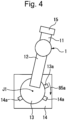
4 ]4 ist eine schematische Draufsicht auf den Roboter und erläutert die erste Steuerung der ersten Robotervorrichtung.[4 ]4 is a schematic plan view of the robot and explains the first control of the first robot device. -
[
5 ]5 ist eine weitere schematische Draufsicht auf den Roboter und erläutert die erste Steuerung der ersten Robotervorrichtung.[5 ]5 is another schematic plan view of the robot and explains the first control of the first robot device. -
[
6 ]6 ist ein erster vergrößerter Querschnitt eines Zahneingriffs.[6 ]6 is a first enlarged cross-section of a tooth mesh. -
[
7 ]7 ist ein zweiter vergrößerter Querschnitt des Zahneingriffs.[7 ]7 is a second enlarged cross-section of the tooth engagement. -
[
8 ]8 ist ein dritter vergrößerter Querschnitt des Zahneingriffs.[8 ]8 is a third enlarged cross-section of the tooth engagement. -
[
9 ]9 ist eine Seitenansicht eines Roboters und erläutert eine zweite Steuerung für die erste Robotervorrichtung.[9 ]9 is a side view of a robot and explains a second controller for the first robot device. -
[
10 ]10 ist eine schematische Draufsicht auf den Roboter und erläutert die zweite Steuerung für die erste Robotervorrichtung.[10 ]10 is a schematic plan view of the robot and explains the second controller for the first robot device. -
[
11 ]11 ist eine weitere schematische Draufsicht auf den Roboter und erläutert die zweite Steuerung für die erste Robotervorrichtung.[11 ]11 is another schematic top view of the robot and explains the second control for the first robot device. -
[
12 ]12 ist eine Seitenansicht eines Roboters und erläutert eine dritte Steuerung für die erste Robotervorrichtung.[12 ]12 is a side view of a robot and explains a third controller for the first robot device. -
[
13 ]13 ist eine Seitenansicht eines Roboters und erläutert eine vierte Steuerung für die erste Robotervorrichtung.[13 ]13 is a side view of a robot and explains a fourth controller for the first robot device. -
[
14 ]14 ist eine Seitenansicht eines Roboters und erläutert eine fünfte Steuerung für die erste Robotervorrichtung.[14 ]14 is a side view of a robot and explains a fifth control for the first robot device. -
[
15 ]15 ist eine weitere Seitenansicht des Roboters und erläutert die fünfte Steuerung der ersten Robotervorrichtung.[15 ]15 is another side view of the robot and explains the fifth control of the first robot device. -
[
16 ]16 ist eine Seitenansicht eines Roboters und erläutert eine sechste Steuerung für die erste Robotervorrichtung.[16 ]16 is a side view of a robot and explains a sixth controller for the first robot device. -
[
17 ]17 ist eine Seitenansicht einer zweiten Robotervorrichtung gemäß einem Ausführungsbeispiel.[17 ]17 is a side view of a second robot device according to an embodiment. -
[
18 ]18 ist ein Blockdiagramm für die zweite Robotervorrichtung.[18 ]18 is a block diagram for the second robot device. -
[
19 ]19 ist eine schematische Draufsicht auf einen Roboter und erläutert die Steuerung der zweiten Robotervorrichtung.[19 ]19 is a schematic plan view of a robot and explains the control of the second robot device. -
[
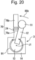
20 ]20 ist eine weitere schematische Draufsicht auf den Roboter und erläutert die Steuerung der zweiten Robotervorrichtung.[20 ]20 is another schematic top view of the robot and explains the control of the second robot device.
Beschreibung von AusführungsbeispielenDescription of implementation examples
Eine Steuerung für einen Roboter gemäß den nachfolgenden Ausführungsbeispielen wird nunmehr mit Blick auf die
Der Roboter 1 hat eine Basis 14, die auf einer Bodenfläche fixiert ist, und ein Drehgelenk 13, welches von der Basis 14 abgestützt ist. Das Drehgelenk 13 dreht um eine erste Antriebsachse J1 in Bezug auf die Basis 14. Der Roboter 1 hat einen oberen Arm 11 und einen unteren Arm 12. Der untere Arm 12 dreht um eine zweite Antriebsachse J2 in Bezug auf das Drehgelenk 13. Der obere Arm 11 dreht um eine dritte Antriebsachse J3 in Bezug auf den unteren Arm 12. Weiterhin dreht der obere Arm 11 um eine vierte Antriebsachse J4, die sich parallel erstreckt zu der Erstreckungsrichtung des oberen Armes 11.The
Der Roboter 1 hat ein Gelenk 15, welches durch den oberen Arm 11 abgestützt ist. Das Gelenk 15 dreht um eine fünfte Antriebsachse J5. Weiterhin enthält das Gelenk 15 einen Flansch 16, welcher um eine sechste Antriebsachse J6 dreht. Das Arbeitswerkzeug 2 ist am Flansch 16 fixiert. Beim vorliegenden Ausführungsbeispiel bilden die Basis 14, das Drehgelenk 13, der untere Arm 12, der obere Arm 11, das Gelenk 15 und das Arbeitswerkzeug 2 Bauteile der Robotervorrichtung 5.The
Der Roboter 1 nach dem vorliegenden Ausführungsbeispiel hat sechs Antriebsachsen, d.h. die Antriebsachsen J1 bis J6, jedoch liegt insoweit keine Einschränkung vor. Ein jeder Roboter kann eingesetzt werden, welcher die Position und Orientierung durch einen Mechanismus ändert. Als Arbeitswerkzeug 2 dient eine Vorrichtung, mit der durch die Robotervorrichtung eine Arbeit ausgeführt wird.The
Ein Roboterkoordinatensystem, also ein Koordinatensystem, dessen Position fixiert ist und in dem die Richtungen der Koordinatenachsen fixiert sind, ist bezüglich der Robotervorrichtung 5 gesetzt. Das Roboterkoordinatensystem wird auch als sogenanntes Weltkoordinatensystem bezeichnet. Weiterhin ist für die Robotervorrichtung 5 ein Flanschkoordinatensystem gesetzt mit einem Ursprung im Flansch 16 des Gelenks 15. Das Flanschkoordinatensystem bewegt sich und dreht zusammen mit einer Oberfläche des Flansches 16. Weiterhin ist für die Robotervorrichtung 5 ein Werkzeugkoordinatensystem gesetzt mit einem Ursprung in irgendeiner Position des Arbeitswerkzeuges. Das Werkzeugkoordinatensystem bewegt sich und dreht sich zusammen mit dem Arbeitswerkzeug. Die Relativposition und -orientierung des Werkzeugkoordinatensystems in Bezug auf das Flanschkoordinatensystem ist konstant und im Voraus festgelegt. Die Position des Roboters 1 entspricht beispielsweise der Position des Ursprungs des Werkzeugkoordinatensystems im Roboterkoordinatensystem. Die Orientierung des Roboters 1 entspricht der Orientierung des Werkzeugkoordinatensystems in Bezug auf das Roboterkoordinatensystem.A robot coordinate system, that is, a coordinate system whose position is fixed and in which the directions of the coordinate axes are fixed, is set with respect to the
Der Roboter 1 hat eine Roboterantriebsvorrichtung, welche die Position und die Orientierung des Roboters 1 ändert. Die Roboterantriebsvorrichtung enthält Antriebsmotoren 22a bis 22f, welche Bauteile antreiben, wie die Arme und das Gelenk. Beim gegebenen Ausführungsbeispiel sind mehrere Antriebsmotoren 22a bis 22f so angeordnet, dass sie den mehreren Antriebsachsen J1 bis J6 jeweils zugeordnet sind. Ein Antriebsmotor ist für jede Antriebsachse vorgesehen. Die Robotervorrichtung 5 enthält eine Antriebsvorrichtung 21 für das Arbeitswerkzeug und treibt dieses an. Die Arbeitswerkzeugantriebsvorrichtung 21 enthält beispielsweise einen Motor, einen Zylinder, ein elektromagnetisches Ventil und dergleichen für den Antrieb des Arbeitswerkzeuges.The
Die Robotervorrichtung 5 enthält eine Steuerung 4, welche den Roboter 1 und das Arbeitswerkzeug 2 steuert. Die Steuerung 4 enthält ein Steuerungsgehäuse 40, welches eingerichtet ist für die Ausführung der Steuerung, und ein Bedienpanel, mit dem eine Bedienungsperson die Steuerung bedient. Die Steuerung 40 enthält eine Recheneinrichtung (einen Computer), welcher wiederum eine zentrale Prozessoreinheit (CPU) aufweist. Die arithmetische Recheneinrichtung hat einen Speicher mit wahlfreiem Zugriff (RAM) und einen Lesespeicher (ROM), welche über einen Bus an die CPU angeschlossen sind.The
Das Bedienpanel 37 ist über Kommunikationseinrichtungen mit der Steuerung 40 verbunden. Das Bedienpanel 37 hat eine Eingabeeinrichtung 38 zum Eingeben von Daten bezüglich des Roboters 1 und bezüglich des Arbeitswerkzeuges 2. Die Eingabeeinrichtung 38 enthält Eingabeelemente, wie beispielsweise eine Tastatur und eine Wähleinrichtung. Das Bedienpanel 37 hat eine Anzeigeeinrichtung 39, welche Daten bezüglich des Roboters 1 und des Arbeitswerkzeuges 2 darstellt. Die Anzeigeeinrichtung 39 kann in geeigneter Weise ausgeführt sein, wie durch eine Flüssigkristallanzeige oder eine Anzeigeeinrichtung auf Basis von organischer Elektrolumineszenz (EL).The
Ein im Voraus erzeugtes Arbeitsprogramm 46 für den Betrieb des Roboters 1 und des Arbeitswerkzeuges 2 wird in die Steuerung 4 eingegeben. Andererseits können auch Lehrpunkte für den Roboter 1 durch die Bedienungsperson über das Bedienpanel 37 zum Antrieb des Roboters 1 eingegeben werden. Die Steuerung 4 kann das Betriebsprogramm 46 für den Roboter 1 und das Arbeitswerkzeug 2 auf Basis der Lehrpunkte generieren.A
Die Steuerung 40 enthält eine Betriebssteuereinheit 43, welche den Betrieb des Roboters 1 und des Arbeitswerkzeuges 2 steuert. Die Betriebssteuereinheit 43 sendet Betriebsbefehle für den Antrieb des Roboters 1 an eine Roboterantriebseinrichtung 45 entsprechend dem Betriebsprogramm 46. Die Roboterantriebseinrichtung 45 enthält elektrische Schaltungen zum Antrieb der Antriebsmotoren 22a bis 22f. Die Roboterantriebseinrichtung 45 liefert elektrische Energie an die Antriebsmotoren 22a bis 22f entsprechend dem Betriebsbefehl. Weiterhin sendet die Betriebssteuereinheit 43 Betriebsbefehle für das Arbeitswerkzeug 2 an die Arbeitswerkzeugantriebseinrichtung 44 entsprechend dem Betriebsprogramm 46. Die Arbeitswerkzeugantriebseinrichtung 44 enthält elektrische Schaltungen zum Antreiben der Arbeitswerkzeugantriebseinrichtung 21. Die Arbeitswerkzeugantriebseinrichtung 44 liefert elektrische Energie entsprechend dem Betriebsbefehl an die Arbeitswerkzeugantriebseinrichtung 21.The
Die Steuerung 40 enthält einen Speicher 42 zum Speichern von Daten bezüglich der Steuerung des Roboters 1 und des Arbeitswerkzeuges 2. Der Speicher 42 kann gebildet sein, zumindest teilweise, aus nicht-flüchtigen Speichermedien, die eingerichtet sind zum Speichern von Daten. Beispielsweise kann der Speicher 42 zusammengesetzt sein aus Speichermedien, wie einem flüchtigen Speicher, einem nicht-flüchtigen Speicher, einem magnetischen Speichermedium oder einem optischen Speichermedium. Das Arbeitsprogramm 46 ist im Speicher 42 abgelegt.The
Die Betriebssteuereinheit 43 ist ein Prozessor, der entsprechend dem Betriebsprogramm 46 betrieben wird. Die Betriebssteuereinheit 43 ist so gestaltet, dass sie im Speicher 42 abgelegte Daten auslesen kann. Der Prozessor liest das Betriebsprogramm 46 aus und führt die Steuerung aus, wie sie im Betriebsprogramm 46 festgelegt ist, damit arbeitet er als Betriebssteuereinheit 43.The
Der Roboter 1 hat Rotationspositionsdetektoren 19a bis 19f zum Detektieren der Position und Orientierung des Roboters 1. Die Rotationspositionsdetektoren 19a bis 19f gemäß dem vorliegenden Ausführungsbeispiel sind an den Antriebsmotoren 22a bis 22f für die jeweiligen Antriebsachsen angebracht. Ein Rotationspositionsdetektor ist jeweils für einen Antriebsmotor vorgesehen. Die jeweiligen Rotationspositionsdetektoren 19a bis 19f können durch einen Codierer konfiguriert sein zum Detektieren eines Drehwinkels einer Ausgangswelle des jeweiligen Antriebsmotors 22a bis 22f. Entsprechend den Ausgangssignalen der mehreren Rotationspositionsdetektoren 19a bis 19f werden die Position und die Orientierung des Roboters 1 detektiert.The
Die Steuerung 4 der ersten Robotervorrichtung 5 hat Drehmomentsensoren 25a bis 25f, die Drehmomente um Antriebsachsen J1 bis J6 an den Gelenken detektieren. Beim vorliegenden Ausführungsbeispiel sind die Drehmomentsensoren 25a bis 25f an allen sechs Antriebsachsen J1 bis J6 angebracht. Ein Drehmomentsensor ist für jede Antriebsachse vorgesehen. Als Drehmomentsensoren 25a bis 25f kommen jegliche Sensoren in Betracht, welche ein Drehmoment detektieren können, wie beispielsweise Dehnungsmessstreifen. Der Drehmomentsensor ist zwischen einem Bauteil des Roboters und einem anderen Bauteil des Roboters angeordnet, wobei Letzteres dreht und dabei durch das andere Bauteil des Roboters abgestützt ist. Beispielsweise ist ein Drehmomentsensor angeordnet zwischen einer Ausgangswelle eines Untersetzungsgetriebes am Antriebsmotor und einem Bauteil, welches durch das Untersetzungsgetriebe angetrieben wird.The
Wie oben beschrieben, sind beim Roboter 1 gemäß der ersten Robotervorrichtung 5 der Antriebsmotor, der Rotationspositionsdetektor und der Drehmomentsensor jeweils für jede Antriebsachse vorgesehen. Beispielsweise detektiert der Rotationspositionsdetektor 19a die Rotationsposition des Antriebsmotors 22a, welcher das Drehgelenk 13 um die Antriebsachse J1 dreht. Der Drehmomentsensor 25a detektiert das Drehmoment um die Antriebsachse J1.As described above, in the
Beim vorliegenden Ausführungsbeispiel werden Masteringdaten des Roboters für jede Antriebsachse generiert. Mit anderen Worten: Masteringdaten werden generiert für den Ausgang des Rotationspositionsdetektors, der an dem Antriebsmotor angebracht ist, welcher seinerseits an jedem Gelenkteil angebracht ist. Beim vorliegenden Ausführungsbeispiel wird eine Antriebsachse, für welche Masteringdaten generiert werden, als spezifische Antriebsachse bezeichnet. Die spezifische Antriebsachse wird im Voraus durch die Bedienungsperson festgelegt.In the present embodiment, mastering data of the robot is generated for each drive axis. In other words, mastering data is generated for the output of the rotation position detector attached to the drive motor which is in turn attached to each joint part. In the present embodiment, a drive axis for which mastering data is generated is called a specific drive axis. The specific drive axis is set in advance by the operator.
Die Steuerung 40 enthält eine arithmetische Betriebseinheit 51, welche eine Kraftsteuerung für den Roboter 1 ausführt auf Basis des Ausgangs des Drehmomentsensors, der an der spezifischen Antriebsachse angeordnet ist. Die arithmetische Betriebseinheit 51 generiert Masteringdaten auf Basis des Ausgangs des Rotationspositionsdetektors, der an dem Antriebsmotor für die spezifische Antriebsachse angeordnet ist. Die arithmetische Betriebseinheit 51 enthält eine Drehmomentsteuereinheit 52, welche den Antriebsmotor so steuert, dass ein Drehmomentausgang vom Drehmomentsensor einen vorab bestimmten Drehmomenteinstellwert 47 hat. Insbesondere steuert die Drehmomentsteuereinheit 52 das Drehmoment, wenn die Rotation des Bauteils des Roboters um die spezifische Antriebsachse durch eine Komponente blockiert ist, letztere ist das Rotationsblockierteil.The
Die arithmetische Betriebseinheit 51 enthält eine Rotationspositionsgewinnungseinheit 53, welche eine Rotationsposition vom Rotationspositionsdetektor gewinnt bezüglich der spezifischen Antriebsachse, wenn das Drehmoment den Drehmomenteinstellwert 47 annimmt. Die arithmetische Betriebseinheit 51 enthält eine Datenerzeugungseinheit 54, welche Masteringdaten generiert für den Ausgang des Rotationspositionsdetektors an der spezifischen Antriebsachse. Die Datenerzeugungseinheit 54 generiert die Masteringdaten auf Basis der Rotationsposition des Antriebsmotors, wie sie durch den Rotationspositionsdetektor ausgegeben ist, und auf Basis eines vorgegebenen Konstruktionswertes 49 bezüglich der Masteringdaten.The
Der Konstruktionswert 49 für das Mastering wird im Voraus festgelegt; es handelt sich um einen theoretischen Wert bezüglich eines Rotationswinkels für jede Antriebsachse zum Ausführen des mastering. Der Konstruktionswert 49 für das Mastering für den Ausgang des Rotationspositionsdetektors, welcher am jeweiligen Antriebsmotor angebracht ist, wird in der Speichereinrichtung 42 abgelegt. Der Konstruktionswert 49 für das Mastering wird für jeden der Rotationspositionsdetektoren 19a bis 19f generiert.The
Die arithmetische Betriebseinheit 51, die Drehmomentsteuereinheit 52, die Rotationspositionsgewinnungseinheit 53 und die Datenerzeugungseinheit 54 sind realisiert mit einem Prozessor, der entsprechend dem Betriebsprogramm 46 arbeitet. Der Prozessor leistet also die Funktionen der jeweiligen Einheit durch Auslesen des Betriebsprogramms 46 und durch Ausführung der Steuerung, wie sie im Betriebsprogramm 46 festgelegt ist.The
Beim vorliegenden Ausführungsbeispiel sind zum Detektieren der Rotationspositionen der Ausgangswellen der Antriebsmotoren 22a bis 22f Rotationspositionsdetektoren 19a bis 19f an den Antriebsachsen J1 bis J6 des Roboters jeweils angeordnet. Für jede der Antriebsachsen J1 bis J6 ist ein Maschinenpulswert, bei dem es sich um eine Rotationsposition des Antriebsmotors handelt, die verwendet wird für die Steuerung des Roboters, definiert durch die nachfolgende Gleichung (1).
![]()
![]()
Beim Masteringbetrieb werden Masteringdaten berechnet. Die Masteringdaten geben eine Rotationsposition an entsprechend der Ursprungsposition des Roboters. Wird ein Ausgangswert des Rotationspositionsdetektors gleich den Masteringdaten, dann nimmt der Maschinenpulswert den Wert 0 an. Der Maschinenpulswert, wie er für die Steuerung des Roboters eingesetzt wird, kann berechnet werden durch Subtraktion der Masteringdaten vom Ausgangswert des Rotationspositionsdetektors.In mastering operation, mastering data is calculated. The mastering data indicates a rotation position corresponding to the original position of the robot. When an output value of the rotation position detector becomes equal to the mastering data, the machine pulse value becomes 0. The machine pulse value used for controlling the robot can be calculated by subtracting the mastering data from the output value of the rotation position detector.
Beispielsweise kann ein Gelenkwinkel jeder Antriebsachse (Gelenkteil) berechnet werden auf Basis eines Maschinenpulswertes und eines Übersetzungsverhältnisses eines Untersetzungsgetriebes. Sodann können Koordinatenwerte der Position und Orientierung des Roboters im Roboterkoordinatensystem berechnet werden durch eine kinematische Conversion auf Basis des Gelenkwinkels eines jeden Gelenkteils. Andererseits kann ein Gelenkwinkel jedes Gelenkteils berechnet werden durch inverse kinematische Conversion auf Basis der Position und Orientierung des Roboters, wie sie im Betriebsprogramm definiert sind. Sodann kann ein Maschinenpulswert berechnet werden auf Basis des Gelenkwinkels und eines Übersetzungsverhältnisses des Untersetzungsgetriebes. Die Steuerung kann die Rotationsposition des Antriebsmotors so steuern, dass der Maschinenpulswert erreicht wird.For example, a joint angle of each drive axis (joint part) can be calculated based on a machine pulse value and a gear ratio of a reduction gear. Then, coordinate values of the position and orientation of the robot in the robot coordinate system can be calculated by kinematic conversion based on the joint angle of each joint part. On the other hand, a joint angle of each joint part can be calculated by inverse kinematic conversion based on the position and orientation of the robot as defined in the operation program. Then, a machine pulse value can be calculated based on the joint angle and a gear ratio of the reduction gear. The controller can control the rotation position of the drive motor so as to achieve the machine pulse value.
Beim vorliegenden Ausführungsbeispiel wird der Roboter um eine spezifische Antriebsachse des Roboters angetrieben. Sodann wird die Rotation des Roboters blockiert durch das Rotationsblockierteil, wie beispielsweise einen Anschlag oder eine Spannvorrichtung. Die Drehmomentsteuereinheit 52 führt die Steuerung dahingehend aus, dass ein Bauteil mit dem vorgegebenen Drehmomenteinstellwert 47 gedrückt wird. Der Konstruktionswert 49 für das Mastering, also ein theoretischer Wert für den Ausgang des Rotationspositionsdetektors dabei, wird im Voraus festgelegt. Die Masteringdaten können dann berechnet werden mit der nachfolgenden Gleichung (2).

Mit der Steuerung gemäß dem vorliegenden Ausführungsbeispiel kann ein hochgenaues Mastering ausgeführt werden. Beim Mastering gemäß dem vorliegenden Ausführungsbeispiel werden die Antriebsmotoren für die Antriebsachsen, die von den spezifischen Antriebsachsen verschieden sind, nicht angetrieben und behalten die vorgegebenen Rotationspositionen bei. Die Gelenkwinkel an den Antriebsachsen, die von den spezifischen Antriebsachsen verschieden sind, werden bei vorgegebenen Werten beibehalten. Sodann wird der Antriebsmotor für die jeweilige spezifische Antriebsachse angetrieben. Deshalb wird empfohlen, ein Mastering mit geringer Genauigkeit vorab auszuführen, bevor das Mastering gemäß dem vorliegenden Ausführungsbeispiel durchgeführt wird. Beispielsweise ist es möglich, vorab ein vorläufiges Mastering auszuführen und eine Anreißlinie über einen Grenzbereich zwischen benachbarten Bauteilen des Roboters zu erzeugen. Die gerade Anreißlinie kann so geformt werden, dass die Rotationsposition eines Bauteils in Bezug auf ein anderes Bauteil bekannt ist. Die Anreißlinie kann für jedes Gelenkteil ausgeführt werden.With the control according to the present embodiment, high-precision mastering can be performed. In mastering according to the present embodiment, the drive motors for the drive axes other than the specific drive axes are not driven and maintain the predetermined rotation positions. The joint angles on the drive axes other than the specific drive axes are maintained at predetermined values. Then, the drive motor for each specific drive axis is driven. Therefore, it is recommended to perform low-precision mastering in advance before performing mastering according to the present embodiment. For example, it is possible to perform preliminary mastering in advance and create a scribe line across a boundary area between adjacent parts of the robot. The straight scribe line can be formed so that the rotation position of one part with respect to another part is known. The scribe line can be performed for each joint part.
Eine Bedienungsperson steuert die Position und Orientierung des Roboters von Hand unter Einsatz eines Bedienpanels derart, dass die Anreißlinie eines Bauteils und die Anreißlinie des anderen Bauteils zueinander ausgerichtet sind. Sind die Anreißlinien an jedem Gelenkteil ausgerichtet, dann sind die Position und die Orientierung für das Mastering gegeben. Dabei kann ein grobes Mastering ausgeführt werden auf Basis des Ausgangs des Rotationspositionsdetektors und eines Konstruktionswertes (theoretischer Wert) der Rotationsposition. Sodann kann das hochgenaue Mastering gemäß dem vorliegenden Ausführungsbeispiel ausgeführt werden.An operator manually controls the position and orientation of the robot using an operation panel so that the scribe line of one part and the scribe line of the other part are aligned. When the scribe lines on each joint part are aligned, the position and orientation for mastering are established. At this time, rough mastering can be performed based on the output of the rotation position detector and a design value (theoretical value) of the rotation position. Then, high-precision mastering can be performed according to the present embodiment.
Die Basis 14 ist ein erstes Bauteil des Roboters 1 und das Drehgelenk 13 ist ein zweites Bauteil, welches um die spezifische Antriebsachse in Bezug auf das erste Bauteil dreht, wie in der Figur durch den Pfeil 85 angedeutet ist. Ein Stopper 13a des Drehgelenkes 13 und ein Stopper 14a der Basis 14 sind so ausgeformt, dass sie eine exzessive Drehung des Drehgelenkes 13 um die Antriebsachse J1 verhindern. Mit anderen Worten: diese (Stopper) sind so angeordnet, dass sie den Drehwinkel des Drehgelenkes 13 einschränken (also den Bereich des Gelenkwinkels in Bezug auf die Antriebsachse J1).The
Bei der ersten Steuerung verhindert das Rotationsblockierteil die unbeschränkte Rotation des Drehgelenkes 13 und enthält den Stopper 14a als Kontaktabschnitt, der an der Basis 14 angeordnet ist, und den Stopper 13a als Kontaktteil, welches an dem Drehgelenk 13 angeordnet ist. Das Rotationsblockierteil ist so ausgeformt, dass bei Drehung des Drehgelenkes 13 entsprechend dem Pfeil 85 der Stopper 13a in Kontakt kommt mit dem Stopper 14a, um so die weitere Rotation des Drehgelenkes 13 zu blockieren.In the first control, the rotation blocking member prevents the unrestricted rotation of the rotary joint 13 and includes the
Kommt der Stopper 13a in Kontakt mit dem Stopper 14a, wird die Drehung des Drehgelenkes 13 blockiert. Die Drehmomentsteuereinheit 52 gewinnt ein Drehmoment vom Drehmomentsensor 25a. Die Drehmomentsteuereinheit 52 steuert den Antriebsmotor 22a so, dass der Drehmomentausgang vom Drehmomentsensor 25a bei Blockierung der Drehung des Drehgelenkes 13 den vorgegebenen Drehmomenteinstellwert 47 hat. Der Drehmomenteinstellwert 47 wird im Voraus festgelegt und im Speicher 42 abgespeichert.When the
Ein jegliches geeignetes Verfahren kann eingesetzt werden für die Steuerung eines am Bauteil wirkenden Drehmoments durch die Drehmomentsteuereinheit 52. Vorzugsweise wird die Steuerung so ausgeführt, dass die Drehgeschwindigkeit des Antriebsmotors reduziert wird, wenn sich das mit dem Drehmomentsensor 25a detektierte Drehmoment dem Zielwert des Drehmomentes annähert. Beispielsweise kann die Drehmomentsteuereinheit 52 eine Dämpfung der Kraftsteuerung ausführen. Bei der Dämpfungssteuerung wird ein Geschwindigkeitsbefehl V berechnet durch Division der Differenz 1 zwischen der momentanen Kraft F und einer vorgegebenen Zielkraft Fd durch einen vorgegebenen Dämpfungskoeffzienten D. Die Gleichung für die Dämpfungs-steuerung kann der nachfolgenden Gleichung (3) entsprechen.
![]()
![]()
Die Drehmomentsteuereinheit 52 kann eine Kraft berechnen durch Division eines mit dem Drehmomentsensor 25a gewonnenen Drehmomentes durch einen vorgegebenen Rotationsradius in Bezug auf ein Drehzentrum an einem Kontaktpunkt. Beispielsweise kann die am Stopper 13a anliegende Kraft F berechnet werden durch Division eines Ausgangs des Drehmomentsensors 25a durch einen Abstand von der Antriebsachse J1 zum Stopper 13a. Dann kann die Dämpfungssteuerung gemäß der obigen Gleichung (3) ausgeführt werden auf Basis der Kraft F, die berechnet ist aus dem Drehmoment, welches wiederum durch den Drehmomentsensor 25a gewonnen ist.The
Die Drehmomentsteuereinheit 52 sendet den Geschwindigkeitsbefehl v für den Antriebsmotor 22a zur Betriebssteuereinheit 43. Die Betriebssteuereinheit 43 kann den Antriebsmotor 22a für die Antriebsachse J1 steuern auf Basis des von der Drehmomentsteuereinheit 52 kommenden Befehls.The
Die Geschwindigkeitsbefehl v kann berechnet werden unter Verwendung einer Gleichung, die gewonnen wird durch Änderung der Zielkraft Fd in ein Zieldrehmoment und durch Änderung der momentanen Kraft F in ein momentanes Drehmoment in der Gleichung (3). Beim vorliegenden Ausführungsbeispiel sind die Drehmomentsensoren 25a bis 25f an allen Antriebsachsen J1 bis J6 angeordnet. Somit kann eine Kraft am Kontaktpunkt zwischen den Stoppern berechnet werden auf Basis aller Ausgänge der Drehmomentsensoren 25a bis 25f. Damit kann der Geschwindigkeitsbefehl für den Antriebsmotor 22a auf Basis der Kraft am Kontaktpunkt berechnet werden.The speed command v can be calculated using an equation obtained by changing the target force Fd into a target torque and changing the instantaneous force F into an instantaneous torque in the equation (3). In the present embodiment, the
Wenn das Drehmomentausgangssignal vom Drehmomentsensor 25a den Drehmomenteinstellwert 47 annimmt, gewinnt die Drehmomentpositionsgewinnungseinheit 53 die Rotationsposition vom Rotationspositionsdetektor 19a bezüglich der Antriebsachse J1. Die Datenerzeugungseinheit 54 generiert Masteringdaten für den Ausgang des Rotationspositionsdetektors 19a an der Antriebsachse J1 auf Basis der obigen Gleichung (2). Die Datenerzeugungseinheit 54 generiert die Masteringdaten auf Basis der Rotationsposition des Antriebsmotors 22a gemäß Ausgabe durch den Rotationspositionsdetektor 19a und des vorab bestimmten Konstruktionswertes 49 der Masteringdaten. Der Speicher 42 speichert die Masteringdaten bezüglich der Antriebsachse J1, wie sie durch die Datenerzeugungseinheit 54 generiert sind.When the torque output from the
Werden die Position und die Orientierung des Roboters 1 bei der tatsächlichen Arbeit der Robotervorrichtung gesteuert, wird ein aus den Masteringdaten berechneter Maschinenpulswert eingesetzt, wie oben durch die Gleichung (1) angegeben ist. Im Ergebnis wird der Roboter so betrieben, dass der Antrieb exakt dem Konstruktionswert des Roboters entspricht. Mit anderen Worten: die Position und Orientierung des Roboters können exakt gesteuert werden, so, dass sie der Position und Orientierung des Roboters seiner Konstruktion entsprechen.When the position and orientation of the
Die Steuerung gemäß dem vorliegenden Ausführungsbeispiel kann das Mastering ausführen mittels des Drehmomentsensors, der an jeder Antriebsachse angeordnet ist. Beim vorliegenden Ausführungsbeispiel wird ein Bauteil des Roboters gedreht und die Drehung wird blockiert durch das Rotationsblockierteil. Dabei steuert die Drehmomentsteuereinheit das Drehmoment so, dass das vorgegebene Bauteil mit dem Drehmomenteinstellwert gedrückt wird. Diese Steuerung stellt sicher, dass die Bauteile, welche die Drehung blockieren, in satten Kontakt miteinander kommen, um so die exakte Position und Orientierung des Roboters zu gewinnen. Beim vorliegenden Ausführungsbeispiel werden Masteringdaten generiert auf Basis der Drehposition, wenn eine vorgegebene Kraft am Kontaktabschnitt des vorgegebenen Bauteils wirkt. Damit kann ein präzises Mastering ausgeführt werden.The controller according to the present embodiment can perform the mastering by means of the torque sensor arranged on each drive axis. In the present embodiment, a member of the robot is rotated and the rotation is blocked by the rotation blocking part. At this time, the torque control unit controls the torque so that the predetermined member is pressed with the torque setting value. This control ensures that the members that block the rotation come into close contact with each other to thereby obtain the accurate position and orientation of the robot. In the present embodiment, mastering data is generated based on the rotation position when a predetermined force acts on the contact portion of the predetermined member. Thus, precise mastering can be performed.
Die Steuerung für einen Roboter gemäß dem vorliegenden Ausführungsbeispiel kann in genauer Weise Masteringdaten durch eine einfache Steuerung generieren. Ein hochgenaues Mastering kann ausgeführt werden, unabhängig von den Erfahrungen der Bedienungsperson. Da die arithmetische Betriebseinheit 52 automatisch den Masteringvorgang ausführt, ist letzteres für die Bedienungsperson einfach und Bedienungsfehler oder dergleichen seitens der Bedienungsperson können verhindert werden.The controller for a robot according to the present embodiment can accurately generate mastering data by simple control. Highly accurate mastering can be performed regardless of the operator's experience. Since the
Auch kann die Steuerung gemäß dem vorliegenden Ausführungsbeispiel das Mastering für jede Antriebsachse ausführen. Anstelle einer Ausführung des Mastering für alle Antriebsachsen, kann das Mastering ausgeführt werden bezüglich der Ausgänge der Rotationspositionsdetektoren für die Antriebsmotoren für einige der Antriebsachsen. Werden beispielsweise einige der Antriebsmotoren oder einige der Rotationspositionsdetektoren ersetzt, kann das Mastering ausgeführt werden für die Antriebsachsen bezüglich der ersetzten Teile. Andererseits kann nach Ausführung eines Mastering mit geringer Genauigkeit, wie das Mastering unter Verwendung einer Anreißlinie, die Steuerung gemäß dem vorliegenden Ausführungsbeispiel für diejenige Antriebsachse ausgeführt werden, für welche ein hochgenaues Mastering erwünscht ist.Also, the controller according to the present embodiment can perform mastering for each drive axis. Instead of performing mastering for all the drive axes, mastering may be performed with respect to the outputs of the rotational position detectors for the drive motors for some of the drive axes. For example, when some of the drive motors or some of the rotational position detectors are replaced, mastering may be performed for the drive axes with respect to the replaced parts. On the other hand, after performing mastering with low accuracy such as mastering using a scribe line, the controller according to the present embodiment can be performed for the drive axis for which high-accuracy mastering is desired.
Es wurde bisher die erste Steuerung für die erste Robotervorrichtung mit einem Mastering bezüglich der Antriebsachse J1 näher beschrieben, jedoch liegt bezüglich der Ausführung insoweit keine Einschränkung vor. Für die anderen Antriebsachsen J2 bis J6 kann die gleiche Steuerung wie bei der ersten Steuerung ausgeführt werden, wenn Stopper vorgesehen sind, welche die Drehbereiche einschränken. Andererseits können Stopper auch bei jedem Roboter so angeordnet werden, dass der Drehwinkel, bei dem der Roboter angetrieben wird, beschränkt ist.The first control for the first robot device with mastering with respect to the drive axis J1 has been described in detail so far, but there is no restriction in terms of the implementation. The same control as for the first control can be implemented for the other drive axes J2 to J6 if stoppers are provided which limit the rotation ranges. On the other hand, stoppers can also be arranged on each robot so that the angle of rotation at which the robot is driven is limited.
Wird der Roboter 1 angetrieben, werden die Ausgänge der Antriebsmotoren 22a bis 22f mittels Untersetzungsgetrieben verlangsamt und sodann auf das jeweilige Bauteil übertragen. Bei jedem Untersetzungsgetriebe sind Zähne miteinander in Eingriff. Somit hat das Spiel (der Rückschlag) in den Eingriffsabschnitten zwischen den Zähnen einen Einfluss. Nunmehr wird eine Steuerung mit Korrektur des Einflusses des Spiels bei der ersten Steuerung näher beschrieben.When the
Entsprechend
Die arithmetische Betriebseinheit 51 detektiert entsprechend den
Die Datenerzeugungseinheit 54 berechnet einen Drehwinkel für die Rotation aus der ersten Rotationsposition in die zweite Rotationsposition entsprechend dem Pfeil 90. Der Winkel, der gewonnen wird durch Subtraktion eines Konstruktionswertes bezüglich des Rotationswinkels von dem Drehwinkel bei tatsächlicher Rotation des Drehgelenkes 13 entspricht dem Drehwinkel δ des Spiels. Die Differenz zwischen den Drehwinkeln gemäß den
Zeigt der Rotationsausgang vom Rotationspositionsdetektor eine negative Richtung an, dann ist der Rotationspositionswert kleiner aufgrund des Spiels und somit kann δ/2 addiert werden zum Maschinenpulswert. Die Datenerzeugungseinheit 54 kann δ/2 subtrahieren von den Masteringdaten. Dreht andererseits die Rotationsposition gemäß dem Rotationspositionsdetektor in positiver Richtung, dann ist das Rotationsausgangssignal größer und somit kann δ/2 von dem Maschinenpulswert subtrahiert werden. Mit anderen Worten: die Datenerzeugungseinheit 54 kann δ/2 zu den Masteringdaten addieren. Auf diese Weise kann die arithmetische Betriebseinheit 51 einen Korrekturwert berechnen bezüglich eines ausgegebenen Pulswertes entsprechend der obigen Gleichung (1). Dementsprechend kann die arithmetische Betriebseinheit 51 den Korrekturwert bezüglich der Masteringdaten berechnen.If the rotation output from the rotation position detector indicates a negative direction, the rotation position value is smaller due to the backlash, and thus δ/2 can be added to the machine pulse value. The
Auf diese Weise kann durch zweimaliges Andrücken in entgegengesetzten Richtungen ein Korrekturwert berechnet werden für die Masteringdaten bezüglich des Spiels. Das Andrücken der Bauteile des Roboters oder das Andrücken des Stoppers, der durch den Roboter abgestützt ist, kann durch zwei Drehungen ausgeführt werden, d.h. eine Drehung in positiver Richtung und eine Drehung in negativer Richtung, wobei dies dreimal oder mehrmals wiederholt werden kann.In this way, by pressing twice in opposite directions, a correction value can be calculated for the mastering data related to the play. Pressing the components of the robot or pressing the stopper supported by the robot can be carried out by two rotations, i.e. one rotation in the positive direction and one rotation in the negative direction, and this can be repeated three or more times.
Die Drehmomentsteuereinheit 52 dreht das Drehgelenk 13 zusammen mit dem unteren Arm 12, dem oberen Arm 11 und dem Gelenk 15 in Richtung des Pfeiles 85a als erste Drehrichtung. Die Rotationspositionen der Antriebsmotoren 22b bis 22f an den anderen Antriebsachsen J2 bis J6 bei Drehung des Drehgelenkes 13 werden im Voraus bestimmt. Die Gelenkwinkel der Antriebsachsen J2 bis J6, also der von der Antriebsachse J1 verschiedenen Achsen, sind fixiert; die Antriebsachse J1 ist also die spezifische Antriebsachse.The
Die Drehmomentsteuereinheit 52 steuert den Antriebsmotor 22a so, dass das von dem Drehmomentsensor 25a bei Kontakt des Gelenkes 15 mit der Einrichtung 71 gemessene Drehmoment den Drehmomenteinstellwert 47 annimmt. Ist das von dem Drehmomentsensor 25a detektierte Drehmoment gleich dem Drehmomenteinstellwert, gewinnt die Rotationspositionsgewinnungseinheit 53 eine erste Rotationsposition vom Rotationspositionsdetektor 19a. Sodann generiert die Datenerzeugungseinheit 54 Masteringdaten auf Basis der ersten Rotationsposition des Antriebsmotors 22a und des Konstruktionswertes 49 der Masteringdaten.The
Die Rotationspositionsgewinnungseinheit 53 gewinnt die erste Rotationsposition, wenn die Drehung in der ersten Richtung gemäß
Bei der dritten Steuerung ändert die Drehmomentsteuereinheit 52 die Position und die Orientierung des Roboters 1 derart, dass der obere Arm 11 und das Gelenk 15 in Bezug auf den unteren Arm 12 nach oben gerichtet sind. Die Gelenkwinkel der Antriebsachsen J1 und J3 bis J6 werden im Voraus bestimmt. Die Drehmomentsteuereinheit 52 treibt die Antriebsmotoren 22a und 22c bis 22f an den Antriebsachsen J1 und J3 bis J6 nicht an, vielmehr werden diese gestoppt gehalten. Die Drehmomentsteuereinheit 52 treibt den Antriebsmotor 22b der Antriebsachse J2 an. Wie durch den Pfeil 86 angezeigt, bringt die Drehmomentsteuereinheit 52 den unteren Arm 12 in Kontakt mit der Einrichtung 71. Sodann steuert die Drehmomentsteuereinheit 52 den Antriebsmotor 22b so, dass der Drehmomentausgang am Drehmomentsensor 25b den vorgegebenen Drehmomenteinstellwert 47 hat.In the third control, the
Sodann detektiert der Rotationspositionsdetektor 19b die Rotationsposition wenn der untere Arm 12 gegen die Einrichtung 71 gedrückt wird. Sodann kann die Datenerzeugungseinheit 54 Masteringdaten generieren auf Basis dieser Rotationsposition und des Konstruktionswertes 49 für das Mastering. Die weiteren Steuerungen, Maßnahmen und Wirkungen entsprechen denen der ersten Steuerung.Then, the
Bei der vierten Steuerung ist eine Einrichtung 73 an dem Drehgelenk 13 fixiert. Die Position und Orientierung der Einrichtung 73 sind präzise justiert. Die Einrichtung 73 bewegt sich zusammen mit dem Drehgelenk 13. Die Einrichtung 73 ist stangenförmig gestaltet. Wie durch den Pfeil 87 angezeigt ist, dreht die Drehmomentsteuereinheit 52 den unteren Arm 12 durch Antrieb des Antriebsmotors 22b an der Antriebsachse J2. Dabei werden die Gelenkwinkel der anderen Antriebsachsen J1 und J3 bis J6 konstant gehalten. In einem Zustand, in dem die Drehmomentsteuereinheit 52 den unteren Arm 12 mit dem vorgegebenen Drehmomenteinstellwert 47 gegen die Einrichtung 73 drückt, gewinnt die Rotationspositionsgewinnungseinheit 53 eine Rotationsposition, die vom Rotationspositionsdetektor 19b ausgegeben wird. Die Datenerzeugungseinheit 54 generiert Masteringdaten für den Ausgang des Rotationspositionsdetektors 19b, der an der Antriebsachse J2 angeordnet ist. Auf diese Weise kann die Einrichtung, welche die Drehung des Bauteils des Roboters an der spezifischen Antriebsachse blockiert, sich zusammen mit dem Bauteil des Roboters bewegen. Die weiteren Steuerungen, Maßnahmen und Wirkungen entsprechen denen der ersten Steuerung.In the fourth control, a
Bei der fünften Steuerung wird eine Einrichtung 74 mit einem ersten Bauteil 74a und einem zweiten Bauteil 74b eingesetzt. Das erste Bauteil 74a ist plattenförmig mit rechteckförmiger Gestalt. Das erste Bauteil 74a ist am Flansch 16 des Gelenks 15 fixiert. Die Oberfläche mit maximalem Flächeninhalt des ersten Bauteils 74a ist am Flansch 16 befestigt. Die Position und die Orientierung des ersten Bauteils 74a kann vom Roboter 1 geändert werden.In the fifth control, a
Andererseits ist das zweite Bauteil 74b unbeweglich. Das zweite Bauteil 74b ist an der Basis 14 fixiert. Die Position und die Orientierung des zweiten Bauteils 14b sind präzise justiert. Andererseits kann das zweite Bauteil 74 auch an einer Installationsoberfläche des Roboters 1 fixiert sein. Die obere Fläche des zweiten Bauteils 74 ist mit einer Ausnehmung 74bx ausgeformt, die rechteckförmig ist. Das erste Bauteil 74a hat Abmessungen, welche ermöglichen, dass das Bauteil in der Ausnehmung 74bx angeordnet werden kann.On the other hand, the
Bei der fünften Steuerung dreht die Drehmomentsteuereinheit 52 das Gelenk 15 um die Antriebsachse J5 in einer Richtung gemäß dem Pfeil 88a, dies ist die erste Richtung. Die Gelenkwinkel der anderen Antriebsachsen J1 bis J4 und J6 werden konstant gehalten. Die Drehmomentsteuereinheit 52 bringt eine Stirnfläche 74aa des ersten Bauteils 74a in Kontakt mit einer Seitenfläche 74ba der Ausnehmung 74bx des zweiten Bauteils 74b. Die Drehmomentsteuereinheit 52 drückt entsprechend dem Ausgang des Drehmomentsensors 25e das erste Bauteil 74a mit dem vorgegebenen Drehmomenteinstellwert 47. Dabei gewinnt die Rotationspositionsgewinnungseinheit 53 eine erste Rotationsposition vom Rotationspositionsdetektor 19e. Sodann kann die Datenerzeugungseinheit 54 Masteringdaten generieren für den Ausgang des Rotationspositionsdetektors 19e auf Basis des Ausgangs vom Rotationspositionsdetektor 19e und des Konstruktionswertes 49 für das Mastering.In the fifth control, the
Die Drehmomentsteuereinheit 52 dreht das Gelenk 15 in Richtung des Pfeiles 88b als zweiter Richtung, entgegengesetzt zur ersten Richtung. Eine Stirnfläche 74ab des ersten Bauteils 74a kommt in Kontakt mit einer Seitenfläche 74bb der Ausnehmung 74bx des zweiten Bauteils 74b. In einem Zustand, in dem das erste Bauteil 74a mit dem Drehmomenteinstellwert 47 gedrückt wird, gewinnt die Rotationspositionsgewinnungseinheit 53 die zweite Rotationsposition des Rotationspositionsdetektors 19e. Die Datenerzeugungseinheit 54 berechnet einen Drehwinkel aus der ersten Rotationsposition zur zweiten Rotationsposition, wie der Pfeil 92 anzeigt. Die Datenerzeugungseinheit 54 kann auf Basis der Differenz zwischen dem tatsächlichen Messwert und dem Konstruktionswert (theoretischer Wert) des Rotationswinkels einen Rotationswinkel (δ/2) berechnen, woraus sich ein Korrekturwert für den Drehwinkel bezüglich des Spiels ergibt.The
Auf diese Weise wird bei der fünften Steuerung ein Korrekturwert bezüglich des Spiels berechnet durch Drehung des Gelenkes 15 in der ersten Richtung und in der zweiten, zur ersten Richtung entgegengesetzten Richtung. Die weiteren Steuerungen, Maßnahmen und Wirkungen entsprechen denen der ersten Steuerung.In this way, in the fifth control, a correction value is calculated with respect to the play by rotating the joint 15 in the first direction and in the second direction opposite to the first direction. The other controls, measures and effects correspond to those of the first control.
Bei der fünften Steuerung werden die Masteringdaten für die fünfte Antriebsachse J5 generiert. Masteringdaten für die dritte Antriebsachse J3 können mit einer ähnlichen Steuerung generiert werden. Mit anderen Worten: durch Antrieb des Antriebsmotors 22c unter Konstanthaltung der Gelenkwinkel der Antriebsachsen J1, J2 und J4 bis J6, also der von der Antriebsachse J3 verschiedenen Achsen, wird das erste Bauteil 74a der Einrichtung 74 gegen die Ausnehmung 74bx des zweiten Bauteils 74b gedrückt. Sodann können durch Detektion der Rotationsposition des Rotationspositionsdetektors 19c an dem Antriebsmotor 22c die Masteringdaten für den Ausgang des Rotationspositionsdetektors 19c generiert werden.In the fifth control, the mastering data for the fifth drive axis J5 is generated. Mastering data for the third drive axis J3 can be generated with a similar control. In other words: by driving the
Bei der sechsten Steuerung ist die Oberfläche mit maximalem Flächeninhalt des ersten Bauteils 74a so angeordnet, dass sie sich in horizontaler Richtung erstreckt. Die Seitenfläche 74ba der Ausnehmung 74bx des zweiten Bauteils 74b und die Stirnfläche 74aa des ersten Bauteils 74a sind jeweils eben ausgeformt. Die Drehmomentsteuereinheit 52 bringt die Stirnfläche 74aa in Oberflächenkontakt mit der Seitenfläche 74ba. Andererseits kann das erste Bauteil 74a auch an einer vorgegebenen Position mit einer vorgegebenen Orientierung so angeordnet sein, dass ein Freiraum gegeben ist zwischen der Seitenfläche 74ba und der Stirnfläche 74aa.In the sixth control, the surface with maximum area of the
Die Drehmomentsteuereinheit 52 dreht das erste Bauteil 74a in einer ersten Richtung, die eine der beiden durch den Pfeil 93 angegebenen Richtungen ist. Die Gelenkwinkel der anderen Antriebsachsen J1 bis J5 werden konstant gehalten. Die Drehmomentsteuereinheit 52 führt eine Steuerung aus, bei der das erste Bauteil 74a gegen das zweite Bauteil 74b mit dem Drehmomenteinstellwert 47 gedrückt wird. Die Drehmomentsteuereinheit 52 steuert den Antriebsmotor 22f so, dass ein mit dem Drehmomentsensor 25f detektiertes Drehmoment den vorgegebenen Drehmomenteinstellwert 47 hat. Die Rotationspositionsgewinnungseinheit 53 gewinnt eine erste Rotationsposition und die Datenerzeugungseinheit 54 kann Masteringdaten für den Ausgang des Rotationspositionsdetektors 19f generieren auf Basis der ersten Rotationsposition.The
Die Drehmomentsteuereinheit 52 dreht das erste Bauteil 74a in einer zweiten Richtung, welche die andere mit dem Pfeil 93 gegebene Richtung ist. In einer Zeitspanne, in welcher die Drehmomentsteuereinheit 52 die Steuerung mit Andrücken des ersten Bauteils 74a mit dem Drehmomenteinstellwert 47 ausführt, gewinnt die Rotationspositionsgewinnungseinheit 53 die zweite Rotationsposition. Die Datenerzeugungseinheit 54 kann einen Korrekturwert bezüglich des Spiels berechnen auf Basis eines Drehwinkels von der ersten Rotationsposition zur zweiten Rotationsposition. Die weiteren Steuerungen, Maßnahmen und Wirkungen sind die gleichen wie bei der ersten Steuerung.The
Bei der sechsten Steuerung werden Masteringdaten für die sechste Antriebsachse J6 generiert, jedoch ist dieses Ausführungsbeispiel nicht darauf beschränkt. Masteringdaten für die J4-Achse können auch mit einer ähnlichen Steuerung generiert werden. Die arithmetische Betriebseinheit 51 treibt den Antriebsmotor 22d so, dass die Stirnfläche 74aa des ersten Bauteils 74a gegen die Seitenfläche 74ba der Ausnehmung 74bx des zweiten Bauteils 74b gedrückt wird. Dann kann die arithmetische Betriebseinheit 51 Masteringdaten generieren für den Rotationspositionsdetektor 19d auf Basis des Ausgangs des Rotationspositionsdetektors 19d.In the sixth control, mastering data for the sixth drive axis J6 is generated, but this embodiment is not limited thereto. Mastering data for the J4 axis can also be generated with a similar control. The
Auf diese Weise können bei der fünften Steuerung und der sechsten Steuerung die Masteringdaten für die Antriebsachsen J3 bis J5 unter Einsatz des Einrichtung 74 generiert werden. Das erste Bauteil der Einrichtung 74 kann eine jegliche Form aufweisen. Auch kann die Ausnehmung im zweiten Bauteil eine jegliche geeignete Form aufweisen. Anstelle des ersten Bauteils 74a mit einer rechteckigen ebenen Form kann auch das erste Bauteil eine abgerundete Form aufweisen. Anstelle einer Ausnehmung 74bx mit rechteckförmiger, ebener Form des zweiten Bauteils 74b kann auch eine Ausnehmung verwendet werden mit abgerundeter Form. Mit derartigen Konfigurationen können Masteringdaten für die Antriebsachsen J1 und J2 generiert werden. In einem Zustand, in dem das erste Bauteil gegen die Vertiefung des zweiten Bauteils gedrückt wird, können Rotationspositionsausgänge der jeweiligen Antriebsmotoren 22a und 22b gewonnen werden. Die Masteringdaten können dann auf Basis der Rotationspositionen erzeugt werden.In this way, in the fifth controller and the sixth controller, the mastering data for the drive axes J3 to J5 can be generated using the
Die Steuerung 7 der zweiten Robotervorrichtung 6 enthält eine Einrichtung 76, welche die Drehung eines Bauteils um eine spezifische Antriebsachse blockiert. Die Einrichtung 76 enthält einen Kraftsensor 24 als Kraftdetektor, welcher eine Kraft in einer vorgegebenen Richtung detektiert. Der Kraftsensor 24 gemäß dem vorliegenden Ausführungsbeispiel kann Kräfte detektieren, die in einer positiven Richtung und in einer negativen Richtung in Bezug auf jede der Achsen wirken (eine X-Achse, eine Y-Achse und eine Z-Achse), wobei die Achsen senkrecht zueinander stehen. Für den Kraft-sensor 74 kann jeder geeignete Sensor eingesetzt werden, wie ein Dehnungsstreifen oder ein Sensor mit Kapazitätsmessung.The controller 7 of the
Die Einrichtung 76 hat ein feststehendes Teil 76a, welches an einer Oberfläche des Kraftsensors 24 befestigt ist, und ein bewegbares Teil 76b, welches an einer anderen Fläche des Kraftsensors 24 befestigt ist. Sowohl das feststehende Teil 76a als auch das bewegbare Teil 76b dieses Ausführungsbeispiels sind stangenförmig. Das feststehende Teil 76a ist an einem Bauteil befestigt, welches ortsfest ist bei Antrieb des Roboters 3. Bei diesem Ausführungsbeispiel ist das feststehende Teil 76a an der Basis 14 des Roboters 3 fixiert. Die Position und die Orientierung der Einrichtung 76 sind präzise justiert.The
Die Steuerung 7 gemäß der zweiten Robotervorrichtung 6 führt eine Kraftsteuerung aus, bei der ein Bauteil der Einrichtung oder die Einrichtung auf Basis des Ausgangs des Kraftsensors 24 gedrückt werden, anstelle des Ausgangs des Drehmomentsensors. Auch bei der zweiten Robotervorrichtung wird das Mastering für jede der Antriebsachsen ausgeführt. Bei diesem Beispiel ist die Antriebsachse J1 als spezifische Antriebsachse ausgewählt.The controller 7 according to the
Die Steuerung 7 hat eine arithmetische Betriebseinheit 61, welche die Kraftsteuerung ausführt und Masteringdaten generiert. Die arithmetische Betriebseinheit 61 hat eine Kraftsteuereinheit 62, welche den Antriebsmotor der spezifischen Antriebsachse so steuert, dass ein Kraftausgang vom Kraftsensor 24 den Krafteinstellwert 48 annimmt. Die Kraftsteuereinheit 62 führt diese Steuerung aus, wenn die Drehung eines Bauteils des Roboters 3 durch die Blockiereinrichtung 76 blockiert ist. Der Krafteinstellwert 48 wird im Voraus festgelegt und in dem Speicher 42 gespeichert.The controller 7 has an
Nimmt der Kraftausgang am Kraftsensor 24 den Krafteinstellwert 48 an, gewinnt die Rotationspositionsaquisitionseinheit 53 die Rotationsposition, die durch den Rotationspositionsdetektor bezüglich der spezifischen Antriebsachse ausgegeben wird. Die Datenerzeugungseinheit 54 generiert Masteringdaten für den Ausgang des Rotationspositionsdetektors an der spezifischen Antriebsachse auf Basis der Rotationsposition des Antriebsmotors, wie er vom Rotationspositionsdetektor ausgegeben wird, und auf Basis des vorgegebenen Konstruktionswertes 49 bezüglich der Masteringdaten.When the force output from the
Die Kraftsteuereinheit 62 dreht das Gelenk 15 in einer Richtung, die durch den Pfeil 85a angegeben ist, diese ist die erste Richtung, durch Antrieb des ersten Antriebsmotors 22a. Das Gelenk 15 kommt in Kontakt mit dem bewegbaren Teil 76b. Die Kraftsteuereinheit 62 steuert den Antriebsmotor 22a auf Basis des Ausgangs des Kraftsensors 24 so, dass die Presskraft, mit welcher das bewegbare Teil 76b durch das Gelenk 15 gedrückt wird, dem Krafteinstellwert 48 entspricht.The
Nimmt der Kraftausgang vom Kraftsensor 24 den Krafteinstellwert 48 an, gewinnt die Rotationspositionsgewinnungseinheit 53 eine erste Rotationsposition, die vom Rotationspositionsdetektor 19a ausgegeben wird. Die Datenerzeugungseinheit 54 kann Masteringdaten generieren für den Ausgang des Rotationspositionsdetektors 19a auf Basis der ersten Rotationsposition des Antriebsmotors 22a, wie durch den Rotationspositionsdetektor 19a ausgegeben, und des Konstruktionswertes 49 bezüglich der Masteringdaten.When the force output from the
Bei der zweiten Robotervorrichtung 6 ist der Kraftsensor 24 an der Einrichtung 76 angeordnet, anstelle des Drehmomentsensors gemäß der ersten Robotervorrichtung. Die Masteringdaten werden generiert durch Ausführung der Kraftsteuerung auf Basis des Ausgangs des Kraftsensors 24. Auch bei der zweiten Robotervorrichtung kann das Mastering mit hoher Genauigkeit und in einfacher Weise ausgeführt werden.In the
Die Kraftsteuereinheit 62 steuert den ersten Antriebsmotor 62a so, dass das bewegbare Teil 76b mit dem vorgegebenen Krafteinstellwert 48 gedrückt wird. Die Rotationspositionsgewinnungseinheit 53 gewinnt eine zweite Rotationsposition während dieses Vorganges. Auf diese Weise wird eine Steuerung der Rotation eines Bauteils in einer ersten Richtung und eine Steuerung der Rotation des Bauteils in einer zweiten, zur ersten Richtung entgegengesetzten Richtung ausgeführt. Die Rotationspositionsgewinnungseinheit 53 gewinnt die erste Rotationsposition, wenn die Rotation in der ersten Richtung blockiert ist und die zweite Rotationsposition, wenn die Rotation in der zweiten Richtung blockiert ist.The
Sodann berechnet die Datenerzeugungseinheit 54 einen Rotationswinkel aus der ersten Rotationsposition zur zweiten Rotationsposition, was durch den Pfeil 91 angedeutet ist, auf Basis der ersten Rotationsposition und der zweiten Rotationsposition. Die Datenerzeugungseinheit 54 kann dann auf Basis dieses Rotationswinkels und eines theoretischen Wertes bezüglich des Rotationswinkels einen Rotationswinkel (δ/2) berechnen, was den Korrekturwert bezüglich des Spiels ergibt.Then, the
Auf diese Weise können die Masteringdaten generiert werden durch Anbringung eines Kraftsensors an einem Bauteil des Roboters oder an einer Blockiereinrichtung zum Andrücken eines Werkstückes. Beispielsweise kann ein Kraftdetektor an der Einrichtung 71 gemäß
Die Einrichtung mit dem Kraftdetektor gemäß dem vorliegenden Ausführungsbeispiel wird beispielsweise stangenförmig ausgeführt, jedoch liegt bezüglich der Form keine Einschränkung vor; vielmehr kann die Einrichtung eine jegliche Form annehmen, die für die Funktion geeignet ist. Die Konfigurationen, Maßnahmen und Wirkungen bezüglich der zweiten Robotervorrichtung sind, wenn nicht vorstehend anders beschrieben, gleich denen der ersten Robotervorrichtung, so dass insoweit sich eine nochmalige Beschreibung erübrigt.The force detector device according to the present embodiment is formed into a rod-shaped form, for example, but there is no limitation on the form; rather, the device may take any form suitable for the function. The configurations, measures and effects of the second robot device are the same as those of the first robot device unless otherwise described above, so that a repeated description is unnecessary.
Bei jeder der oben beschriebenen Steuerungen kann die Abfolge der Schritte geändert werden, sofern die Funktionen und Wirkungen nicht verloren gehen.For each of the controls described above, the sequence of steps can be changed as long as the functions and effects are not lost.
Die oben beschriebenen Ausführungsbeispiele können angemessen kombiniert werden. In den oben beschriebenen Figuren sind die gleichen oder gleichwertigen Komponenten mit den gleichen Bezugszeichen versehen. Anzumerken ist, dass die oben beschriebenen Ausführungen beispielhaft sind und den Umfang der Erfindung nicht einschränken. Ausführungen und Abwandlungen der Beispiele sind in den Patentansprüchen enthalten.The embodiments described above can be combined as appropriate. In the figures described above, the same or equivalent components are provided with the same reference numerals. It should be noted that the embodiments described above are examples and do not limit the scope of the invention. Embodiments and modifications of the examples are included in the patent claims.
BezugszeichenlisteList of reference symbols
- 1, 31, 3
- Roboterrobot
- 4, 74, 7
- Steuerungsteering
- 5, 65, 6
- RobotervorrichtungRobot device
- 1111
- oberer Armupper arm
- 1212
- unterer Armlower arm
- 1313
- DrehgelenkSwivel joint
- 13a13a
- Stopperstopper
- 1414
- Basisbase
- 14a14a
- Stopperstopper
- 1515
- Gelenkjoint
- 1616
- Flanschflange
- 19a bis 19f19a to 19f
- RotationspositionsdetektorRotation position detector
- 22a bis 22f22a to 22f
- AntriebsmotorDrive motor
- 2424
- KraftsensorForce sensor
- 25a bis 25f25a to 25f
- DrehmomentsensorTorque sensor
- 3737
- BedienpanelControl panel
- 3838
- EingabeeinrichtungInput device
- 3939
- AnzeigeeinrichtungDisplay device
- 4040
- Steuerungsteering
- 4242
- Speichermemory
- 4747
- DrehmomenteinstellwertTorque setting value
- 4848
- KrafteinstellwertForce setting value
- 4949
- Konstruktionswert bezüglich MasteringConstruction value regarding mastering
- 5252
- DrehmomentsteuereinheitTorque control unit
- 5353
- RotationspositionsgewinnungseinheitRotation position acquisition unit
- 5454
- DatenerzeugungseinheitData generation unit
- 6262
- KraftsteuereinheitForce control unit
- 71, 73, 74, 7571, 73, 74, 75
- Einrichtung zum BlockierenBlocking facility
- 74a74a
- erstes Bauteilfirst component
- 74b74b
- zweites Bauteilsecond component
- 7676
- Einrichtung zum BlockierenBlocking facility
ZITATE ENTHALTEN IN DER BESCHREIBUNGQUOTES INCLUDED IN THE DESCRIPTION
Diese Liste der vom Anmelder aufgeführten Dokumente wurde automatisiert erzeugt und ist ausschließlich zur besseren Information des Lesers aufgenommen. Die Liste ist nicht Bestandteil der deutschen Patent- bzw. Gebrauchsmusteranmeldung. Das DPMA übernimmt keinerlei Haftung für etwaige Fehler oder Auslassungen.This list of documents listed by the applicant was generated automatically and is included solely for the better information of the reader. The list is not part of the German patent or utility model application. The DPMA accepts no liability for any errors or omissions.
Zitierte PatentliteraturCited patent literature
- JP 2016221642 A [0006]JP 2016221642 A [0006]
- JP 8171410 A [0006]JP 8171410 A [0006]
Claims (8)
Applications Claiming Priority (1)
| Application Number | Priority Date | Filing Date | Title |
|---|---|---|---|
| PCT/JP2021/047092 WO2023119378A1 (en) | 2021-12-20 | 2021-12-20 | Control device for robot performing mastering through torque or force control |
Publications (1)
| Publication Number | Publication Date |
|---|---|
| DE112021008372T5 true DE112021008372T5 (en) | 2024-09-12 |
Family
ID=86901580
Family Applications (1)
| Application Number | Title | Priority Date | Filing Date |
|---|---|---|---|
| DE112021008372.4T Pending DE112021008372T5 (en) | 2021-12-20 | 2021-12-20 | Control device for robots with mastering by torque or force control |
Country Status (6)
| Country | Link |
|---|---|
| US (1) | US12528201B2 (en) |
| JP (1) | JP7750984B2 (en) |
| CN (1) | CN118354877A (en) |
| DE (1) | DE112021008372T5 (en) |
| TW (1) | TW202327832A (en) |
| WO (1) | WO2023119378A1 (en) |
Citations (1)
| Publication number | Priority date | Publication date | Assignee | Title |
|---|---|---|---|---|
| JP2016221642A (en) | 2015-06-02 | 2016-12-28 | セイコーエプソン株式会社 | Robot, robot control device, robot control method and robot system |
Family Cites Families (21)
| Publication number | Priority date | Publication date | Assignee | Title |
|---|---|---|---|---|
| US5103404A (en) * | 1985-12-06 | 1992-04-07 | Tensor Development, Inc. | Feedback for a manipulator |
| JPH08171410A (en) * | 1994-12-19 | 1996-07-02 | Fanuc Ltd | Robot mastering method |
| JP2002036164A (en) * | 2000-07-24 | 2002-02-05 | Takagi Ind Co Ltd | Fall prevention device |
| JP3994956B2 (en) * | 2002-12-18 | 2007-10-24 | ソニー株式会社 | Robot device, load absorbing device and load absorbing method |
| JP4498024B2 (en) * | 2004-06-15 | 2010-07-07 | キヤノン株式会社 | Optical encoder |
| JP4271249B2 (en) * | 2007-06-14 | 2009-06-03 | ファナック株式会社 | Mating device |
| JP4598849B2 (en) * | 2008-09-03 | 2010-12-15 | ファナック株式会社 | Fitting device for correcting clogged fitting |
| JP4837113B2 (en) * | 2010-03-18 | 2011-12-14 | ファナック株式会社 | Fitting device using robot |
| CN102893513B (en) * | 2010-05-17 | 2015-04-01 | 三菱电机株式会社 | Device for controlling a motor |
| JP5689704B2 (en) * | 2010-08-08 | 2015-03-25 | 日本電産サンキョー株式会社 | Motor control device and motor control method |
| JP6004626B2 (en) * | 2011-10-12 | 2016-10-12 | キヤノン株式会社 | Encoder system, apparatus with position detection function, and copying machine |
| KR20130080909A (en) * | 2012-01-06 | 2013-07-16 | 삼성전자주식회사 | Surgical robot and method for controlling the same |
| JP2016028842A (en) * | 2014-07-17 | 2016-03-03 | 株式会社ロボテック | Actuator system |
| JP6752576B2 (en) * | 2016-01-13 | 2020-09-09 | キヤノン株式会社 | Drive mechanism, robot device, control method of drive mechanism, control method of robot device, manufacturing method of article, control program, recording medium, and support member |
| JP2017177255A (en) * | 2016-03-29 | 2017-10-05 | ソニー株式会社 | Control apparatus and control method |
| US10081102B1 (en) * | 2016-06-02 | 2018-09-25 | X Development Llc | Antagonistic output actuation |
| JP6474381B2 (en) * | 2016-12-22 | 2019-02-27 | ファナック株式会社 | Spot welding system with tip dresser for polishing electrodes |
| JP7267688B2 (en) * | 2018-05-31 | 2023-05-02 | キヤノン株式会社 | Robot system, robot arm control method, article manufacturing method, driving device, and driving device control method |
| US11691293B2 (en) * | 2018-08-31 | 2023-07-04 | Fanuc Corporation | Robot |
| JP6841802B2 (en) * | 2018-08-31 | 2021-03-10 | ファナック株式会社 | Robots and robot systems |
| JP6836571B2 (en) * | 2018-11-14 | 2021-03-03 | ファナック株式会社 | Robot device |
-
2021
- 2021-12-20 DE DE112021008372.4T patent/DE112021008372T5/en active Pending
- 2021-12-20 CN CN202180104832.6A patent/CN118354877A/en active Pending
- 2021-12-20 WO PCT/JP2021/047092 patent/WO2023119378A1/en not_active Ceased
- 2021-12-20 US US18/713,705 patent/US12528201B2/en active Active
- 2021-12-20 JP JP2023568786A patent/JP7750984B2/en active Active
-
2022
- 2022-11-24 TW TW111145019A patent/TW202327832A/en unknown
Patent Citations (1)
| Publication number | Priority date | Publication date | Assignee | Title |
|---|---|---|---|---|
| JP2016221642A (en) | 2015-06-02 | 2016-12-28 | セイコーエプソン株式会社 | Robot, robot control device, robot control method and robot system |
Also Published As
| Publication number | Publication date |
|---|---|
| CN118354877A (en) | 2024-07-16 |
| JPWO2023119378A1 (en) | 2023-06-29 |
| JP7750984B2 (en) | 2025-10-07 |
| WO2023119378A1 (en) | 2023-06-29 |
| TW202327832A (en) | 2023-07-16 |
| US20250033220A1 (en) | 2025-01-30 |
| US12528201B2 (en) | 2026-01-20 |
Similar Documents
| Publication | Publication Date | Title |
|---|---|---|
| DE102007050232B4 (en) | Handling robot and method for controlling a handling robot | |
| DE3142406C2 (en) | Program control for a manipulator | |
| DE69411130T2 (en) | Method and device for calibrating the axes of movement of an industrial robot | |
| DE3587396T2 (en) | Handling device with a movable structure. | |
| DE2754436A1 (en) | COMPUTER-CONTROLLED MANIPULATOR WITH SIX DEGREES OF FREEDOM | |
| DE102015219141A1 (en) | Method and device for measuring a numerically controlled machine tool | |
| WO2008046620A1 (en) | System and method for calibrating a handling device | |
| WO2018019550A1 (en) | Method for controlling an end element of a machine tool, and machine tool | |
| DE102017126243A1 (en) | SYSTEM AND METHOD FOR COMPENSATING MULTIPLE MANUFACTURING SYSTEMS | |
| DE102020209486B3 (en) | ACTUATOR | |
| EP3712552A1 (en) | Method for calibrating a measurement sensor in a gear cutting machine | |
| DE102017209178B4 (en) | Method for determining the spatial position of a moving coordinate system, a measuring point of its sensor or an operating point of a tool in a robot | |
| DE102019134488B4 (en) | industrial robot system | |
| DE602006000541T2 (en) | Servo control apparatus and method for adjusting a servo system | |
| EP1398094B1 (en) | Method and device for determining the arm length of bent products | |
| DE102020126209A1 (en) | ROBOT | |
| EP3441200A1 (en) | Referencing method and device for industrial robots | |
| EP0729005A1 (en) | Measuring device with 6 degrees of freedom | |
| EP3839153A1 (en) | Method for calibrating a position sensor | |
| DE102016013083B4 (en) | Calibrate a model of a process robot and operate a process robot | |
| DE112021008372T5 (en) | Control device for robots with mastering by torque or force control | |
| EP4323160B1 (en) | Automated manufacturing machine calibration | |
| DE102022213548B4 (en) | Robot with different torque sensors in different joints | |
| DE112023006429T5 (en) | Control device, parameter correction procedure and program | |
| DE102012206503B4 (en) | Method for force control |
Legal Events
| Date | Code | Title | Description |
|---|---|---|---|
| R012 | Request for examination validly filed |