DE112021004275T5 - Electric transmission with hydrodynamic bearing - Google Patents
Electric transmission with hydrodynamic bearing Download PDFInfo
- Publication number
- DE112021004275T5 DE112021004275T5 DE112021004275.0T DE112021004275T DE112021004275T5 DE 112021004275 T5 DE112021004275 T5 DE 112021004275T5 DE 112021004275 T DE112021004275 T DE 112021004275T DE 112021004275 T5 DE112021004275 T5 DE 112021004275T5
- Authority
- DE
- Germany
- Prior art keywords
- hydrodynamic bearing
- bearing
- rotor
- electric transmission
- arrangement according
- Prior art date
- Legal status (The legal status is an assumption and is not a legal conclusion. Google has not performed a legal analysis and makes no representation as to the accuracy of the status listed.)
- Withdrawn
Links
Images


Classifications
-
- F—MECHANICAL ENGINEERING; LIGHTING; HEATING; WEAPONS; BLASTING
- F16—ENGINEERING ELEMENTS AND UNITS; GENERAL MEASURES FOR PRODUCING AND MAINTAINING EFFECTIVE FUNCTIONING OF MACHINES OR INSTALLATIONS; THERMAL INSULATION IN GENERAL
- F16H—GEARING
- F16H57/00—General details of gearing
- F16H57/02—Gearboxes; Mounting gearing therein
- F16H57/037—Gearboxes for accommodating differential gearings
-
- B—PERFORMING OPERATIONS; TRANSPORTING
- B60—VEHICLES IN GENERAL
- B60K—ARRANGEMENT OR MOUNTING OF PROPULSION UNITS OR OF TRANSMISSIONS IN VEHICLES; ARRANGEMENT OR MOUNTING OF PLURAL DIVERSE PRIME-MOVERS IN VEHICLES; AUXILIARY DRIVES FOR VEHICLES; INSTRUMENTATION OR DASHBOARDS FOR VEHICLES; ARRANGEMENTS IN CONNECTION WITH COOLING, AIR INTAKE, GAS EXHAUST OR FUEL SUPPLY OF PROPULSION UNITS IN VEHICLES
- B60K1/00—Arrangement or mounting of electrical propulsion units
-
- F—MECHANICAL ENGINEERING; LIGHTING; HEATING; WEAPONS; BLASTING
- F16—ENGINEERING ELEMENTS AND UNITS; GENERAL MEASURES FOR PRODUCING AND MAINTAINING EFFECTIVE FUNCTIONING OF MACHINES OR INSTALLATIONS; THERMAL INSULATION IN GENERAL
- F16C—SHAFTS; FLEXIBLE SHAFTS; ELEMENTS OR CRANKSHAFT MECHANISMS; ROTARY BODIES OTHER THAN GEARING ELEMENTS; BEARINGS
- F16C17/00—Sliding-contact bearings for exclusively rotary movement
- F16C17/02—Sliding-contact bearings for exclusively rotary movement for radial load only
- F16C17/028—Sliding-contact bearings for exclusively rotary movement for radial load only with fixed wedges to generate hydrodynamic pressure, e.g. multi-lobe bearings
-
- F—MECHANICAL ENGINEERING; LIGHTING; HEATING; WEAPONS; BLASTING
- F16—ENGINEERING ELEMENTS AND UNITS; GENERAL MEASURES FOR PRODUCING AND MAINTAINING EFFECTIVE FUNCTIONING OF MACHINES OR INSTALLATIONS; THERMAL INSULATION IN GENERAL
- F16C—SHAFTS; FLEXIBLE SHAFTS; ELEMENTS OR CRANKSHAFT MECHANISMS; ROTARY BODIES OTHER THAN GEARING ELEMENTS; BEARINGS
- F16C32/00—Bearings not otherwise provided for
- F16C32/06—Bearings not otherwise provided for with moving member supported by a fluid cushion formed, at least to a large extent, otherwise than by movement of the shaft, e.g. hydrostatic air-cushion bearings
- F16C32/0629—Bearings not otherwise provided for with moving member supported by a fluid cushion formed, at least to a large extent, otherwise than by movement of the shaft, e.g. hydrostatic air-cushion bearings supported by a liquid cushion, e.g. oil cushion
-
- F—MECHANICAL ENGINEERING; LIGHTING; HEATING; WEAPONS; BLASTING
- F16—ENGINEERING ELEMENTS AND UNITS; GENERAL MEASURES FOR PRODUCING AND MAINTAINING EFFECTIVE FUNCTIONING OF MACHINES OR INSTALLATIONS; THERMAL INSULATION IN GENERAL
- F16C—SHAFTS; FLEXIBLE SHAFTS; ELEMENTS OR CRANKSHAFT MECHANISMS; ROTARY BODIES OTHER THAN GEARING ELEMENTS; BEARINGS
- F16C32/00—Bearings not otherwise provided for
- F16C32/06—Bearings not otherwise provided for with moving member supported by a fluid cushion formed, at least to a large extent, otherwise than by movement of the shaft, e.g. hydrostatic air-cushion bearings
- F16C32/0662—Details of hydrostatic bearings independent of fluid supply or direction of load
-
- F—MECHANICAL ENGINEERING; LIGHTING; HEATING; WEAPONS; BLASTING
- F16—ENGINEERING ELEMENTS AND UNITS; GENERAL MEASURES FOR PRODUCING AND MAINTAINING EFFECTIVE FUNCTIONING OF MACHINES OR INSTALLATIONS; THERMAL INSULATION IN GENERAL
- F16C—SHAFTS; FLEXIBLE SHAFTS; ELEMENTS OR CRANKSHAFT MECHANISMS; ROTARY BODIES OTHER THAN GEARING ELEMENTS; BEARINGS
- F16C33/00—Parts of bearings; Special methods for making bearings or parts thereof
- F16C33/02—Parts of sliding-contact bearings
- F16C33/04—Brasses; Bushes; Linings
- F16C33/20—Sliding surface consisting mainly of plastics
- F16C33/201—Composition of the plastic
-
- H—ELECTRICITY
- H02—GENERATION; CONVERSION OR DISTRIBUTION OF ELECTRIC POWER
- H02K—DYNAMO-ELECTRIC MACHINES
- H02K5/00—Casings; Enclosures; Supports
- H02K5/04—Casings or enclosures characterised by the shape, form or construction thereof
- H02K5/16—Means for supporting bearings, e.g. insulating supports or means for fitting bearings in the bearing-shields
- H02K5/167—Means for supporting bearings, e.g. insulating supports or means for fitting bearings in the bearing-shields using sliding-contact or spherical cap bearings
- H02K5/1672—Means for supporting bearings, e.g. insulating supports or means for fitting bearings in the bearing-shields using sliding-contact or spherical cap bearings radially supporting the rotary shaft at both ends of the rotor
-
- H—ELECTRICITY
- H02—GENERATION; CONVERSION OR DISTRIBUTION OF ELECTRIC POWER
- H02K—DYNAMO-ELECTRIC MACHINES
- H02K7/00—Arrangements for handling mechanical energy structurally associated with dynamo-electric machines, e.g. structural association with mechanical driving motors or auxiliary dynamo-electric machines
- H02K7/006—Structural association of a motor or generator with the drive train of a motor vehicle
-
- H—ELECTRICITY
- H02—GENERATION; CONVERSION OR DISTRIBUTION OF ELECTRIC POWER
- H02K—DYNAMO-ELECTRIC MACHINES
- H02K7/00—Arrangements for handling mechanical energy structurally associated with dynamo-electric machines, e.g. structural association with mechanical driving motors or auxiliary dynamo-electric machines
- H02K7/08—Structural association with bearings
- H02K7/083—Structural association with bearings radially supporting the rotary shaft at both ends of the rotor
-
- H—ELECTRICITY
- H02—GENERATION; CONVERSION OR DISTRIBUTION OF ELECTRIC POWER
- H02K—DYNAMO-ELECTRIC MACHINES
- H02K7/00—Arrangements for handling mechanical energy structurally associated with dynamo-electric machines, e.g. structural association with mechanical driving motors or auxiliary dynamo-electric machines
- H02K7/10—Structural association with clutches, brakes, gears, pulleys or mechanical starters
- H02K7/116—Structural association with clutches, brakes, gears, pulleys or mechanical starters with gears
-
- B—PERFORMING OPERATIONS; TRANSPORTING
- B60—VEHICLES IN GENERAL
- B60K—ARRANGEMENT OR MOUNTING OF PROPULSION UNITS OR OF TRANSMISSIONS IN VEHICLES; ARRANGEMENT OR MOUNTING OF PLURAL DIVERSE PRIME-MOVERS IN VEHICLES; AUXILIARY DRIVES FOR VEHICLES; INSTRUMENTATION OR DASHBOARDS FOR VEHICLES; ARRANGEMENTS IN CONNECTION WITH COOLING, AIR INTAKE, GAS EXHAUST OR FUEL SUPPLY OF PROPULSION UNITS IN VEHICLES
- B60K17/00—Arrangement or mounting of transmissions in vehicles
- B60K17/04—Arrangement or mounting of transmissions in vehicles characterised by arrangement, location or kind of gearing
- B60K17/12—Arrangement or mounting of transmissions in vehicles characterised by arrangement, location or kind of gearing of electric gearing
-
- B—PERFORMING OPERATIONS; TRANSPORTING
- B60—VEHICLES IN GENERAL
- B60K—ARRANGEMENT OR MOUNTING OF PROPULSION UNITS OR OF TRANSMISSIONS IN VEHICLES; ARRANGEMENT OR MOUNTING OF PLURAL DIVERSE PRIME-MOVERS IN VEHICLES; AUXILIARY DRIVES FOR VEHICLES; INSTRUMENTATION OR DASHBOARDS FOR VEHICLES; ARRANGEMENTS IN CONNECTION WITH COOLING, AIR INTAKE, GAS EXHAUST OR FUEL SUPPLY OF PROPULSION UNITS IN VEHICLES
- B60K1/00—Arrangement or mounting of electrical propulsion units
- B60K2001/001—Arrangement or mounting of electrical propulsion units one motor mounted on a propulsion axle for rotating right and left wheels of this axle
-
- F—MECHANICAL ENGINEERING; LIGHTING; HEATING; WEAPONS; BLASTING
- F16—ENGINEERING ELEMENTS AND UNITS; GENERAL MEASURES FOR PRODUCING AND MAINTAINING EFFECTIVE FUNCTIONING OF MACHINES OR INSTALLATIONS; THERMAL INSULATION IN GENERAL
- F16C—SHAFTS; FLEXIBLE SHAFTS; ELEMENTS OR CRANKSHAFT MECHANISMS; ROTARY BODIES OTHER THAN GEARING ELEMENTS; BEARINGS
- F16C2380/00—Electrical apparatus
- F16C2380/26—Dynamo-electric machines or combinations therewith, e.g. electro-motors and generators
-
- F—MECHANICAL ENGINEERING; LIGHTING; HEATING; WEAPONS; BLASTING
- F16—ENGINEERING ELEMENTS AND UNITS; GENERAL MEASURES FOR PRODUCING AND MAINTAINING EFFECTIVE FUNCTIONING OF MACHINES OR INSTALLATIONS; THERMAL INSULATION IN GENERAL
- F16H—GEARING
- F16H57/00—General details of gearing
- F16H57/02—Gearboxes; Mounting gearing therein
- F16H2057/02034—Gearboxes combined or connected with electric machines
-
- F—MECHANICAL ENGINEERING; LIGHTING; HEATING; WEAPONS; BLASTING
- F16—ENGINEERING ELEMENTS AND UNITS; GENERAL MEASURES FOR PRODUCING AND MAINTAINING EFFECTIVE FUNCTIONING OF MACHINES OR INSTALLATIONS; THERMAL INSULATION IN GENERAL
- F16H—GEARING
- F16H57/00—General details of gearing
- F16H57/02—Gearboxes; Mounting gearing therein
- F16H2057/02039—Gearboxes for particular applications
- F16H2057/02043—Gearboxes for particular applications for vehicle transmissions
- F16H2057/02052—Axle units; Transfer casings for four wheel drive
Landscapes
- Engineering & Computer Science (AREA)
- General Engineering & Computer Science (AREA)
- Mechanical Engineering (AREA)
- Power Engineering (AREA)
- Chemical & Material Sciences (AREA)
- Combustion & Propulsion (AREA)
- Transportation (AREA)
- Physics & Mathematics (AREA)
- Fluid Mechanics (AREA)
- Sliding-Contact Bearings (AREA)
- General Details Of Gearings (AREA)
Abstract
Bei einem Aspekt wird eine verbesserte Elektrogetriebeanordnung bereitgestellt, die ein hydrodynamisches Lager einschließt. Die Elektrogetriebeanordnung schließt einen Stator ein, der innerhalb eines äußeren Gehäuses angeordnet ist. Ein Rotor ist so konfiguriert, dass er durch den Stator drehend angetrieben wird. Der Rotor kann eine Rotorwelle einschließen, die ein erstes Zahnrad aufweist, das so konfiguriert ist, dass es antriebsmäßig mit einem Differenzial in Eingriff steht. Zwischen der Rotorwelle und dem äußeren Gehäuse ist ein hydrodynamisches Lager angeordnet. Das hydrodynamische Lager ist aus einem nichtleitfähigen Material gebildet. Insbesondere kann das hydrodynamische Lager aus einem Polymer- oder Kunststoffmaterial gebildet sein. Bei einem Aspekt ist das hydrodynamische Lager aus einem nichtmetallischen Material gebildet.

Description
EINBEZIEHUNG DURCH BEZUGNAHMEINCLUSION BY REFERENCE
Diese Anmeldung beansprucht Priorität gegenüber der nicht vorläufigen
GEBIET DER ERFINDUNGFIELD OF THE INVENTION
Die vorliegende Offenbarung ist auf eine Elektrogetriebeanordnung gerichtet und betrifft insbesondere das Bereitstellen hydrodynamischer Lager für die Elektrogetriebeanordnung.The present disclosure is directed to an electric transmission assembly and is particularly concerned with providing hydrodynamic bearings for the electric transmission assembly.
HINTERGRUNDBACKGROUND
Es ist allgemein bekannt, dass Automobilgetriebe im Allgemeinen verwendet werden, um Leistung von einer Brennkraftmaschine (internal combustion engine, ICE) zu Fahrzeugrädern zu leiten, während ein Drehzahlverhältnis zwischen den Rädern und der ICE eingestellt wird, um sicherzustellen, dass die ICE effizient arbeitet. Da eine wachsende Nachfrage besteht, Fahrzeuge verbrauchsärmer zu machen, verwenden einige Fahrzeuge jetzt Elektromotoren, um die ICE zu ergänzen oder zu ersetzen.It is well known that automotive transmissions are generally used to route power from an internal combustion engine (ICE) to vehicle wheels while adjusting a speed ratio between the wheels and the ICE to ensure that the ICE operates efficiently. With a growing demand to make vehicles more fuel efficient, some vehicles are now using electric motors to supplement or replace the ICE.
Automobilgetriebe enthalten typischerweise eine Anzahl von Wellen, die sich relativ zu einem feststehenden Gehäuse drehen. Bei einigen Anordnungen können die Wellen so konfiguriert sein, dass sie sich relativ zueinander drehen. Lager werden verwendet, um eine relative Drehung zu ermöglichen, während ein beliebiges Schleppmoment minimiert wird. Die Lager sind im Allgemeinen so ausgelegt, dass sie Kräfte zwischen Komponenten mit relativer Drehung übertragen. Es ist allgemein bekannt, Radiallager zum Übertragen beliebiger radialer Belastungen zu verwenden und Axiallager oder Drucklager zum Übertragen beliebiger axialer Belastungen zu verwenden. Auch Kombinationslager sind bekannt und im Allgemeinen so konfiguriert, dass sie sowohl radiale als auch axiale Lasten übertragen oder stützen.Automotive transmissions typically include a number of shafts that rotate relative to a stationary housing. In some arrangements, the shafts can be configured to rotate relative to one another. Bearings are used to allow relative rotation while minimizing any drag torque. Bearings are generally designed to transmit forces between components with relative rotation. It is well known to use radial bearings to transfer any radial loads and to use thrust bearings or thrust bearings to transfer any axial loads. Combination bearings are also known and are generally configured to transmit or support both radial and axial loads.
Wälzlager, die einen zwischen gegenüberliegenden Ringen gelagerten Wälzkörper einschließen, werden auch häufig bei Automobilgetrieben verwendet. Die Wälzkörper sind in erster Linie so konfiguriert, dass sie im Gegensatz zu einem Gleitkontakt einen Rollkontakt mit den Lagerringen aufrechterhalten. Lagerbuchsen, die ebenfalls bei Automobilgetrieben verwendet werden können, sind eine andere Art von Lagern, die überwiegend Gleitkontakt verwenden und typischerweise aus Materialien mit einem niedrigen Reibungskoeffizienten gebildet sind, um den Widerstand zu minimieren.Rolling element bearings, which include a rolling element supported between opposing rings, are also commonly used in automotive transmissions. The rolling elements are primarily configured to maintain rolling contact with the bearing rings as opposed to sliding contact. Bushings, which can also be used in automotive transmissions, are another type of bearing that primarily uses sliding contact and are typically formed from materials with a low coefficient of friction to minimize drag.
Zwar sind diese verschiedenen Lagertypen bekannt, sie haben jedoch Mängel. Zum Beispiel kann sich während des Betriebs eine elektrostatische Ladung aufbauen, und diese Art von Lagern kann elektrischen Strömen ausgesetzt sein, die durch sie fließen. Dies verursacht typischerweise eine Beschädigung der Lageroberflächen und verursacht daher einen vorzeitigen Ausfall der Lager. Eine bekannte Lösung zum Behandeln des Stromproblems besteht darin, Isolierbeschichtungen oder andere Arten von Nebenschlüssen zu verwenden, um dazu beizutragen, einen Stromdurchgang durch die Lager zu verhindern. Diese Lösungen sind in der Regel mit hohem Arbeitsaufwand zu installieren oder teuer.While these various types of bearings are known, they have shortcomings. For example, an electrostatic charge can build up during operation, and these types of bearings can be subject to electrical currents flowing through them. This typically causes damage to the bearing surfaces and therefore causes premature bearing failure. A known solution to addressing the current problem is to use insulating coatings or other types of shunts to help prevent current passage through the bearings. These solutions are typically laborious to install or expensive.
Dementsprechend wäre es wünschenswert, eine verbesserte Lösung bereitzustellen, um die elektrischen Stromprobleme bei Lagern anzugehen, die bei Elektromotoranordnungen auftreten.Accordingly, it would be desirable to provide an improved solution to address the bearing electrical current problems associated with electric motor assemblies.
KURZDARSTELLUNGEXECUTIVE SUMMARY
Bei einem Aspekt wird eine verbesserte Elektrogetriebeanordnung bereitgestellt, die ein hydrodynamisches Lager einschließt. Die Elektrogetriebeanordnung schließt einen Stator ein, der innerhalb eines äußeren Gehäuses angeordnet ist. Ein Rotor ist so konfiguriert, dass er durch den Stator drehend angetrieben wird. Der Rotor kann eine Rotorwelle einschließen, die ein erstes Zahnrad aufweist, das so konfiguriert ist, dass es antriebsmäßig mit einem Differenzial in Eingriff steht. Zwischen der Rotorwelle und dem äußeren Gehäuse ist ein hydrodynamisches Lager angeordnet. Das hydrodynamische Lager ist aus einem nichtleitfähigen Material gebildet. Insbesondere kann das hydrodynamische Lager aus einem Polymer- oder Kunststoffmaterial gebildet sein. Bei einem Aspekt ist das hydrodynamische Lager aus einem nichtmetallischen Material gebildet.In one aspect, an improved electric transmission assembly that includes a hydrodynamic bearing is provided. The electric transmission assembly includes a stator disposed within an outer housing. A rotor is configured to be rotationally driven by the stator. The rotor may include a rotor shaft having a first gear configured to drivingly engage a differential. A hydrodynamic bearing is located between the rotor shaft and the outer housing. The hydrodynamic bearing is formed from a non-conductive material. In particular, the hydrodynamic bearing can be formed from a polymer or plastic material. In one aspect, the hydrodynamic bearing is formed from a non-metallic material.
Das hydrodynamische Lager kann ein erstes hydrodynamisches Lager an einem ersten axialen Ende des Rotors und ein zweites hydrodynamisches Lager an einem zweiten axialen Ende des Rotors einschließen. Das erste hydrodynamische Lager kann so konfiguriert sein, dass es mit einem zentralen Gehäuse des äußeren Gehäuses in Eingriff steht, und das zweite hydrodynamische Lager kann so konfiguriert sein, dass es mit einer ersten Endkappe des äußeren Gehäuses in Eingriff steht. Die hydrodynamischen Lager können entweder auf die jeweiligen Gehäusebauteile aufgepresst oder über Passungsmerkmale drehfest oder fest mit den feststehenden Gehäusekomponenten verbunden sein.The hydrodynamic bearing may include a first hydrodynamic bearing at a first axial end of the rotor and a second hydrodynamic bearing at a second axial end of the rotor. The first hydrodynamic bearing may be configured to engage a center housing of the outer housing and the second hydrodynamic bearing may be configured to engage a first end cap of the outer housing. The hydrodynamic bearings can either be pressed onto the respective housing components or connected to the stationary housing components in a rotationally fixed or fixed manner via fitting features.
Das hydrodynamische Lager kann einen sich radial erstreckenden Flansch, der eine erste Lageroberfläche definiert, und einen sich axial erstreckenden Flansch einschließen, der eine zweite Lageroberfläche definiert. Der sich radial erstreckende Flansch und der sich axial erstreckende Flansch können einstückig miteinander ausgebildet sein. Bei einem weiteren Aspekt können der sich radial erstreckende Flansch und der sich axial erstreckende Flansch getrennt voneinander ausgebildet sein.The hydrodynamic bearing may include a radially extending flange defining a first bearing surface and an axially extending flange defining a second bearing surface. The radially extending flange and the axially extending flange may be integrally formed with each other. In another aspect, the radially extending flange and the axially extending flange may be formed separately from each other.
Das hydrodynamische Lager kann ein Verdrehsicherungselement einschließen, das konfiguriert ist, um das hydrodynamische Lager drehbar an einer anderen Komponente des Getriebes wie etwa dem äußeren Gehäuse zu fixieren.The hydrodynamic bearing may include an anti-rotation element configured to rotatably fix the hydrodynamic bearing to another component of the transmission, such as the outer housing.
Das hydrodynamische Lager schließt bei einem Aspekt eine Lageroberfläche auf mindestens einer aus einer radialen Lageroberfläche oder einer axialen Lageroberfläche ein, die ein Profil aufweist, das einen flachen Abschnitt mit Nutabschnitten an jedem Ende des flachen Abschnitts einschließt. Bei einem weiteren Aspekt kann das hydrodynamische Lager eine Lageroberfläche auf mindestens einer aus einer radialen Lageroberfläche oder einer axialen Lageroberfläche einschließen, die ein Profil aufweist, das einen flachen Abschnitt mit geneigten Abschnitten an jedem Ende des flachen Abschnitts und Nutabschnitte an jeweiligen Enden der geneigten Abschnitte umfasst.The hydrodynamic bearing, in one aspect, includes a bearing surface on at least one of a radial bearing surface or an axial bearing surface that has a profile that includes a flat portion with groove portions at each end of the flat portion. In another aspect, the hydrodynamic bearing may include a bearing surface on at least one of a radial bearing surface or an axial bearing surface that has a profile that includes a flat section with inclined sections at each end of the flat section and groove sections at respective ends of the inclined sections.
Das Differenzial kann so konfiguriert sein, dass es mit einer ersten Ausgangswelle und einer zweiten Ausgangswelle in Eingriff steht, und die erste Ausgangswelle und die zweite Ausgangswelle können jeweils so konfiguriert sein, dass sie ein Fahrzeugrad antreiben.The differential may be configured to engage a first output shaft and a second output shaft, and the first output shaft and the second output shaft may each be configured to drive a vehicle wheel.
Bei einem Aspekt weist die Rotorwelle einen zentralen Hohlraum auf, der so bemessen ist, dass er mindestens eine der ersten Ausgangswelle oder der zweiten Ausgangswelle darin aufnimmt.In one aspect, the rotor shaft has a central cavity sized to receive at least one of the first output shaft and the second output shaft therein.
Das erste Zahnrad kann so konfiguriert sein, dass es mit einem zweiten Zahnrad in Eingriff steht, das mit einer Vorgelegewelle verbunden ist, und die Vorgelegewelle kann ein drittes Zahnrad einschließen, das so konfiguriert ist, dass es mit einem vierten Zahnrad in Eingriff steht, das mit dem Differenzial verbunden ist. Die Vorgelegewelle kann gegenüber der Rotorwelle versetzt und entlang einer parallelen Achse zu einer Achse der Rotorwelle angeordnet sein. Die Vorgelegewelle kann radial außerhalb des Differenzials angeordnet sein.The first gear may be configured to mesh with a second gear connected to a countershaft, and the countershaft may include a third gear configured to mesh with a fourth gear connected to the differential. The countershaft may be offset from the rotor shaft and disposed along an axis parallel to an axis of the rotor shaft. The countershaft can be arranged radially outside of the differential.
Zusätzliche Ausführungsformen sind hierin offenbart.Additional embodiments are disclosed herein.
Figurenlistecharacter list
Die vorstehende Kurzdarstellung und die nachstehende ausführliche Beschreibung werden besser verstanden, wenn sie in Verbindung mit den beigefügten Zeichnungen gelesen werden, die eine bevorzugte Ausführungsform der Offenbarung veranschaulichen. In den Zeichnungen:
- ist
1A eine seitliche Querschnittsansicht eines Getriebes gemäß einem Aspekt, das eine kombinierte Radiallagerkomponente und eine Axial- oder Drucklagerkomponente einschließt. - ist
1B eine vergrößerte seitliche Querschnittsansicht des Getriebes von1A . - ist
2 eine vergrößerte seitliche Querschnittsansicht eines Getriebes gemäß einem weiteren Aspekt, bei dem das hydrodynamische Lager ein separat ausgebildetes Radiallager und ein separat ausgebildetes Axial- oder Drucklager einschließt. - ist
3A eine perspektivische Ansicht eines hydrodynamischen Lagers gemäß einem Aspekt. - ist
3B eine seitliche Querschnittsansicht des hydrodynamischen Lagers von3A . - ist
3C eine Ansicht des hydrodynamischen Lagers der3A und3B in der Axialebene. - ist
3D eine vergrößerte Ansicht eines Abschnitts der Lageroberfläche des hydrodynamischen Lagers der3A bis3C . - ist
4A eine perspektivische Ansicht eines hydrodynamischen Lagers gemäß einem weiteren Aspekt. - ist
4B eine Querschnittsansicht des hydrodynamischen Lagers von4A . - ist
4C eine Ansicht des hydrodynamischen Lagers der4A und4B in der Axialebene. - ist
4D eine vergrößerte Ansicht eines Abschnitts der Lageroberfläche des hydrodynamischen Lagers der4A bis4C . - ist
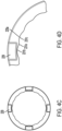
5A ist eine Vorderansicht eines hydrodynamischen Lagers in der Axialebene gemäß einem weiteren Aspekt. - ist
5B eine perspektivische des hydrodynamischen Lagers von5A . - ist
5C eine vergrößerte Ansicht eines Abschnitts einer axialen Lageroberfläche des hydrodynamischen Lagers der5A bis5B . - ist
5D eine vergrößerte Ansicht eines Abschnitts einer radialen Lageroberfläche des hydrodynamischen Lagers der5A bis5C . - ist
5E eine Querschnittsansicht, die eine Berührungsfläche zwischen dem hydrodynamischen Lager der5A bis5D und anderen Komponenten des Getriebes zeigt. - ist
6A eine perspektivische Ansicht eines hydrodynamischen Lagers gemäß einem weiteren Aspekt. - ist
6B eine Ansicht des hydrodynamischen Lagers von6A in der Axialebene. - ist
6C eine vergrößerte Ansicht eines Abschnitts einer Lageroberfläche des hydrodynamischen Lagers der6A bis6B .
- is
1A - is
1B FIG. 12 is an enlarged cross-sectional side view of the transmission of FIG1A . - is
2 14 is an enlarged cross-sectional side view of a transmission according to another aspect in which the hydrodynamic bearing includes a separately formed radial bearing and a separately formed thrust or thrust bearing. - is
3A - is
3B FIG. 14 is a cross-sectional side view of the hydrodynamic bearing of FIG3A . - is
3C a view of the hydrodynamic bearing of the3A and3B in the axial plane. - is
3D FIG. 14 is an enlarged view of a portion of the bearing surface of the hydrodynamic bearing of FIG3A until3C . - is
4A a perspective view of a hydrodynamic bearing according to another aspect. - is
4B FIG. 12 is a cross-sectional view of the hydrodynamic bearing of FIG4A . - is
4C a view of the hydrodynamic bearing of the4A and4B in the axial plane. - is
4D FIG. 14 is an enlarged view of a portion of the bearing surface of the hydrodynamic bearing of FIG4A until4C . - is
5A 13 is a front view of a hydrodynamic bearing in the axial plane according to another aspect. - is
5B a perspective of the hydrodynamic bearing of FIG5A . - is
5C 5A until5B . - is
5D 5A until5C . - is
5E FIG. 12 is a cross-sectional view showing an interface between the hydrodynamic bearing of FIG5A until5D and other components of the transmission. - is
6A a perspective view of a hydrodynamic bearing according to another aspect. - is
6B a view of the hydrodynamic bearing of6A in the axial plane. - is
6C 6A until6B .
AUSFÜHRLICHE BESCHREIBUNG DER BEVORZUGTEN AUSFÜHRUNGSFORMENDETAILED DESCRIPTION OF THE PREFERRED EMBODIMENTS
Eine bestimmte Terminologie wird in der folgenden Beschreibung lediglich zur Vereinfachung verwendet und ist nicht einschränkend. Die Begriffe „vorderer/vordere/vorderes“, „hinterer/hintere/hinteres“, „oberer/obere/oberes“, „unterer/untere/unteres“ bezeichnen Richtungen in den Zeichnungen, auf die Bezug genommen wird. Die Begriffe „nach innen“ und „nach außen“ beziehen sich auf Richtungen zu und von den Teilen, auf die in den Zeichnungen Bezug genommen wird. „Axial“ bezieht sich auf eine Richtung entlang der Achse einer Welle. Ein Verweis auf eine Liste von Elementen, die als „mindestens eines aus a, b oder c“ bezeichnet werden (wobei a, b und c die aufgeführten Elemente darstellen), bedeutet ein beliebiges einzelnes der Elemente a, b oder c oder Kombinationen davon. Die Terminologie schließt die vorstehend konkret erwähnten Begriffe, Ableitungen davon und Begriffe ähnlicher Bedeutung ein.Certain terminology is used in the following description for convenience only and is not limiting. The terms "front/front/front", "rear/rear/rear", "upper/upper/upper", "lower/lower/lower" indicate directions in the drawings to which reference is made. The terms "inward" and "outward" refer to directions to and from the parts referred to in the drawings. "Axial" refers to a direction along the axis of a shaft. A reference to a list of items identified as "at least one of a, b, or c" (where a, b, and c represent the listed items) means any one of a, b, or c, or combinations thereof. The terminology includes the terms specifically mentioned above, derivatives thereof and terms of similar import.
Wie in den
Ein Elektromotor ist in das Getriebe 10 integriert und so konfiguriert, dass er Leistung erzeugt. Bei einem Aspekt schließt der Elektromotor einen Stator 18 ein. Der Stator 18 kann an einer anderen Komponente des Getriebes 10 befestigt sein. Der Stator 18 kann an einer Innenoberfläche von einem des zentralen Gehäuses 12, der ersten Endkappe 14 oder der zweiten Endkappe 16 befestigt sein. Bei einem Aspekt ist der Stator 18 an dem zentralen Gehäuse 12 befestigt.An electric motor is integrated into
Der Elektromotor schließt einen Rotor 20 ein. Der Rotor 20 kann radial innerhalb oder außerhalb des Stators 18 angeordnet sein. Der Rotor 20 ist im Allgemeinen so konfiguriert oder gelagert, dass er sich dreht. Bei einem Aspekt ist der Rotor 20 an einer Rotorwelle 22 befestigt. Zwar ist in den Figuren eine separate Rotorwelle 22 gezeigt, jedoch würde ein Fachmann verstehen, dass die Rotorwelle 22 in anderen Aspekten einstückig mit dem Rotor 20 ausgebildet sein könnte.The electric motor includes a
Die Rotorwelle 22 kann einen zentralen Hohlraum einschließen, wie hierin ausführlicher beschrieben. Ein erstes Ende 22a der Rotorwelle 22 ist so konfiguriert, dass es zur Drehung relativ zu dem zentralen Gehäuse 12 über mindestens eine erste Lagerhalterung gelagert ist. Bei einem Aspekt umfasst die erste Lagerhalterung ein erstes hydrodynamisches Lager 24. Ein zweites, gegenüberliegendes Ende 22b der Rotorwelle 22 ist zur Drehung relativ zu der ersten Endkappe 14 über mindestens eine zweite Lagerhalterung gelagert. Die zweite Lagerhalterung kann ein zweites hydrodynamisches Lager 26 umfassen.The
Bei einem Aspekt ist der Elektromotor im Allgemeinen an einem axialen Ende des Getriebes 10 bereitgestellt. An einem anderen axialen Ende des Getriebes 10 kann ein Differenzial 28 bereitgestellt sein. Das Differenzial 28 kann so konfiguriert sein, dass es die Leistungsabgabe auf eine erste Ausgangswelle 30 und eine zweite Ausgangswelle 32 unterteilt oder aufteilt. Das Differenzial 28 wird im Allgemeinen durch die Rotorwelle 22 über eine Reihe von Verbindungen oder Zahnrädern angetrieben, die hierin ausführlicher beschrieben werden. Die erste und die zweite Ausgangswelle 30, 32 können so konfiguriert sein, dass sie Leistung auf ein jeweiliges Rad des Fahrzeugs übertragen oder an dieses abgeben. Das Differenzial 28 kann bei einem Aspekt ein Kegelraddifferenzial sein. Einem Fachmann würde klar sein, dass alternative Arten von Differenzialen verwendet werden können. Bei einem Beispiel kann jede der Ausgangswellen 30, 32 mit einem Gleichlaufgelenk enden, um mit einer Halbwelle verbunden zu werden, die mit einer Radeinheit verbunden ist.In one aspect, the electric motor is generally provided at an axial end of the
Das Differenzial 28 und die erste und zweite Ausgangswelle 30, 32 sind so konfiguriert, dass sie wie der Rotor 20 zur Drehung um dieselbe Achse, d. h. Achse (X), gelagert sind. Die erste Ausgangswelle 30 ist so konfiguriert, dass sie sich durch den zentralen Hohlraum der Rotorwelle 22 erstreckt. Das Differenzial 28 kann einen Träger 34 einschließen, der ein radial äußeres Gehäuse oder eine radial äußere Komponente bereitstellt. Lager 36 und 38 sind zwischen dem Träger 34 und dem äußeren Gehäuse 11, d. h. dem Träger 12 und der zweiten Endkappe 16, bereitgestellt. Die erste Ausgangswelle 30 ist an einem ersten Ende 30a durch das Differenzial 28 und an einem zweiten Ende 30b durch ein Lager 40 gelagert. In ähnlicher Weise ist die zweite Ausgangswelle 32 an einem ersten Ende 32a durch Differenzial 28 und an einem zweiten Ende 32b durch ein Lager 42 gelagert.The differential 28 and the first and
Es kann eine Vorgelegewelle 44 bereitgestellt sein, die innerhalb des äußeren Gehäuses 11 des Getriebes 10 angeordnet ist. Die Vorgelegewelle 44 ist versetzt zur Achse (X) angeordnet. Eine Achse der Vorgelegewelle 44 verläuft parallel zur Achse (X). Die Vorgelegewelle 44 ist drehbar durch ein Paar Lager 46 und 48 gelagert, die an axial gegenüberliegenden Enden der Vorgelegewelle 44 angeordnet sind. Die Vorgelegewelle 44 kann radial außerhalb des Differenzials 28 angeordnet sein. Diese Anordnung stellt ein axial kompaktes Getriebe 10 bereit.A
Bei einem Aspekt ist ein erstes Zahnrad 50 mit der Rotorwelle 22 verbunden. Das erste Zahnrad 50 kann einstückig mit der Rotorwelle 22 ausgebildet sein. Bei einem Aspekt ist das erste Zahnrad 50 an dem ersten Ende 22a der Rotorwelle 22 befestigt. Das erste Zahnrad 50 ist so konfiguriert, dass es mit einem zweiten Zahnrad 52 in Eingriff steht, das mit der Vorgelegewelle 44 verbunden ist, d. h. antriebsmäßig in Eingriff steht. Das zweite Zahnrad 52 kann bei einem Aspekt einstückig mit der Vorgelegewelle 44 ausgebildet sein. Ein drittes Zahnrad 54 ist mit der Vorgelegewelle 44 verbunden. Bei einem Aspekt ist das dritte Zahnrad 54 einstückig in der Vorgelegewelle 44 ausgebildet. Das dritte Zahnrad 54 ist so konfiguriert, dass es mit einem vierten Zahnrad 56 in Eingriff steht. Bei einem Aspekt ist das vierte Zahnrad 56 mit dem Träger 34 des Differenzials 28 verbunden. Das vierte Zahnrad 56 könnte direkt an einer radial äußeren Oberfläche des Trägers 34 ausgebildet sein.In one aspect, a
Die Rotorwelle 22, die Vorgelegewelle 44 und das erste, das zweite, das dritte und das vierte Zahnrad 50, 52, 54 und 54 sind so konfiguriert, dass sie den Rotor 20 antriebsmäßig mit dem Differenzial 28 verbinden. Diese Komponenten und das Differenzial 28 verbinden den Rotor 20 antriebsmäßig mit der ersten und der zweiten Ausgangswelle 30, 32.The
In dem in dieser Offenbarung verwendeten Sinne werden Komponenten als antriebsmäßig verbunden angesehen, wenn Leistung zwischen ihnen übertragen wird. In dem in dieser Offenbarung verwendeten Sinne können antriebsmäßig verbundene Komponenten direkt zusammenwirken oder eingreifen oder können indirekt zusammenwirken oder eingreifen und über Zwischenkomponenten verbunden sein. Komponenten können durch lösbare Kraftflusskomponenten wie etwa Kupplungen oder Bremsen selektiv antriebsmäßig verbunden werden.As used in this disclosure, components are considered to be drivingly connected when power is transferred between them. As used in this disclosure, drivingly connected components may be directly cooperating or intermeshing, or may be indirectly cooperating or intermeshing and connected via intermediate components. Components can be selectively drivingly connected through detachable power flow components such as clutches or brakes.
Eine äußere radiale Oberfläche 27a des zweiten hydrodynamischen Lagers 26 ist so konfiguriert, dass sie mit einer radialen Stützoberfläche 62 der ersten Endkappe 14 in Eingriff steht oder mit dieser eine Berührungsfläche bildet. Eine innere radiale Oberfläche 27b des zweiten hydrodynamischen Lagers 26 ist so konfiguriert, dass sie mit der radialen Oberfläche 22c der Stützwelle 22 in Eingriff steht oder mit dieser eine Berührungsfläche bildet.An outer
Eine äußere axiale Oberfläche 25c des ersten hydrodynamischen Lagers 24 ist so konfiguriert, dass sie mit einer entsprechenden axialen Endfläche 64 des zentralen Gehäuses 12 in Eingriff steht. Eine innere axiale Oberfläche 25d des ersten hydrodynamischen Lagers 24 ist so konfiguriert, dass sie mit einer entsprechenden axialen Endfläche 20a des Rotors 20 in Eingriff steht.An outer
Eine äußere axiale Oberfläche 27c des zweiten hydrodynamischen Lagers 26 ist so konfiguriert, dass sie mit einer entsprechenden axialen Endfläche 66 der ersten Endkappe 14 in Eingriff steht. Eine innere axiale Oberfläche 27d des zweiten hydrodynamischen Lagers 26 ist so konfiguriert, dass sie mit einer entsprechenden axialen Endfläche 20b des Rotors 20 in Eingriff steht.An outer
Fluid wie etwa Schmierfluid wird zwischen den Berührungsflächen zwischen den hydrodynamischen Lagern 24, 26 und dem Rotor 20 und der Rotorwelle 22 gerichtet oder geleitet. Genutete Oberflächen, die hierin ausführlicher beschrieben werden, sind auf den Oberflächen der hydrodynamischen Lager 24, 26 bereitgestellt, die dem Rotor 20 und der Rotorwelle 22 zugewandt sind oder mit diesem in Eingriff stehen. Insbesondere schließen die innere axiale Oberfläche 25d und die innere radiale Oberfläche 25b des ersten hydrodynamischen Lagers 24 und die innere axiale Oberfläche 27d und die innere radiale Oberfläche 27b des zweiten hydrodynamischen Lagers 26 hydrodynamische Lageroberflächen ein, die im Allgemeinen so konfiguriert sind, dass sie Fluid wie etwa Schmierfluid richten oder leiten. Bei einem Aspekt kann Fluid aus einem externen gekühlten Vorratsbehälter und/oder Pumpensystem oder einem Ölbadsystem mit Umwälzkühlung zugeführt werden, das das Ölvolumen in der Getriebeanordnung nutzt.Fluid, such as lubricating fluid, is directed or directed between the interfaces between the
Merkmale auf diesen Oberflächen verteilen als Reaktion auf eine relative Drehung das Fluid zu einem Film. Beispielsweise kann die Richtung der relativen Drehung basierend auf dem Vorwärts- oder Rückwärtsfahrmodus im Uhrzeigersinn oder gegen den Uhrzeigersinn sein. Bei einem Aspekt trennt der Film die Oberflächen, sodass die Reibung minimiert wird. Es können sowohl axiale als auch radiale Kräfte übertragen werden. Beispielhafte Auslegungen, Merkmale, Lagerprofile und andere Aspekte eines hydrodynamischen Lagers sind in der am 3. März 2020 eingereichten
Bei einem Aspekt sind die hydrodynamischen Lager 24, 26 an dem äußeren Gehäuse 11 wie etwa dem zentralen Gehäuse 12, oder der ersten Endkappe 14 befestigt, und der hydrodynamische Film kann zwischen dem hydrodynamischen Lager 24, 26 und mindestens einem des Rotors 20 oder der Rotorwelle 22 ausgebildet sein. Einem Fachmann würde klar sein, dass die hydrodynamischen Lager bei einer alternativen Konfiguration oder Anordnung an dem Rotor 20 und/oder der Rotorwelle 22 befestigt sein können.In one aspect, the
Die hydrodynamischen Lager können Verdrehsicherungselemente wie etwa die Elemente 129, 229, 429 einschließen, die in den
Im Betrieb können Wellenspannungen und der Strom, die durch den Motor erzeugt werden, über herkömmliche Lagerwälzkörper zu dem äußeren Gehäuse abgeleitet werden. Dies kann zu einer Lichtbogenbildung führen, die die tribologischen Eigenschaften der Lageroberfläche und der Wälzkörper verschlechtert und die Mikrostruktur des Materials verschlechtert, wodurch ein vorzeitiger Ausfall der Lager verursacht wird. Um diese Probleme zu behandeln, können das erste und das zweite hydrodynamische Lager 24 und 26 aus einem nichtleitenden Material wie etwa einem Polymermaterial oder Kunststoffmaterial gebildet sein, das nicht durch ein elektrisches Potenzial beeinträchtigt oder beeinflusst wird. Bei einem Aspekt kann das nichtleitfähige Material Hochleistungsthermoplaste, technische Thermoplaste oder duroplastische Kunststoffe einschließen. Somit sind die polymeren hydrodynamischen Lager 24, 26 wirksam bei der Vermeidung beliebiger Probleme im Zusammenhang mit elektrostatischer Aufladung oder Entladung, die andernfalls die Lager beschädigen und einen vorzeitigen Ausfall der Lager verursachen können.In operation, shaft voltages and the current generated by the motor can be dissipated to the outer housing via conventional bearing rollers. This can lead to arcing, which degrades the tribological properties of the bearing surface and rolling elements, and degrades the microstructure of the material, causing premature bearing failure. To address these issues, the first and second
Das hierin offenbarte hydrodynamische Lager kann im Allgemeinen so konfiguriert sein, dass es einen lasttragenden Ölfilm zwischen Lager- oder gegenüberliegenden Oberflächen des hydrodynamischen Lagers und einer angrenzenden Komponente wie etwa einer Berührungsfläche mit dem Rotor 20 und der Rotorwelle 22, erzeugt. Während des Drehbetriebs wird Öl oder beliebiges anderes Schmierfluid in den Kontakt zwischen den Oberflächen des hydrodynamischen Lagers 24, 26 und den gegenüberliegenden Oberflächen des Rotors 20 und der Rotorwelle 22 zugeführt, um einen keilförmigen Ölfilm, der die Drucklast trägt, sowie einen keilförmigen radiallasttragender Ölfilm zu erzeugen.The hydrodynamic bearing disclosed herein can generally be configured to create a load-bearing oil film between bearing or opposing surfaces of the hydrodynamic bearing and an adjacent component, such as an interface with
Verschiedene Stützoberflächen der hydrodynamischen Lager 24, 26 können variieren und verschiedene Profile einschließen. Wie in den
Die radiale Lageroberfläche 125a des hydrodynamischen Lagers 124 der
Das in den
Das hydrodynamische Lager 124 der
Die
Die radialen Lageroberflächen 225a, 225a' können ein Profil aufweisen, das einen flachen Abschnitt 231 a mit Nutabschnitten 231b, 231c auf gegenüberliegenden Seiten des flachen Abschnitts 231a einschließt. Die Nutabschnitte 231b, 231c weisen jeweils ein kontinuierlich gekrümmtes Profil bzw. eine kontinuierlich gekrümmte Oberfläche auf. Dieses Profil kann sich um einen Umfang der radialen Lageroberflächen 225a, 225a' wiederholen.The
Das in den
Das hydrodynamische Lager 224 der
Die
Die radiale Lageroberfläche 325a kann ein Profil aufweisen, das einen flachen Abschnitt 331a mit Nutabschnitten 331b, 331c auf gegenüberliegenden Seiten des flachen Abschnitts 331a einschließt. Die Nutabschnitte 331b, 331c weisen bei einem Aspekt ein kontinuierlich gekrümmtes Profil oder eine kontinuierlich gekrümmte Oberfläche auf. Dieses Profil kann sich um einen Umfang der radialen Lageroberfläche 325a wiederholen. Die axiale Lageroberfläche 325b kann ein Profil einschließen, das einen flachen Abschnitt 333a mit geneigten Abschnitten 333b, 333c an gegenüberliegenden Enden des flachen Abschnitts 333a aufweist. Jeweilige Nutabschnitte 333d, 333e sind an jeweiligen gegenüberliegenden Enden der geneigten Abschnitte 333b, 333c angeordnet. Die geneigten Abschnitte 333b, 333c können eine flache, aber abgewinkelte Oberfläche oder ein flaches, aber abgewinkeltes Profil aufweisen. Die Nutabschnitte 333d, 333e können eine kontinuierlich gekrümmte Oberfläche bzw. ein kontinuierlich gekrümmtes Profil aufweisen. Die geneigten Abschnitte 333b, 333c der Lageroberfläche 325b können relativ zu dem benachbarten flachen Abschnitt 333a um einen Winkel von 0,25 bis 3 Grad abgewinkelt sein.
Die
Die in einer der Figuren wie etwa den
Bei einem Aspekt sind die hierin offenbarten hydrodynamischen Lager bidirektionale Lager für hohe Drehzahlen, die entweder nur radiale, nur axiale oder kombinierte radiale und axiale Lager sein können. In dem in diesem Dokument verwendeten Sinne bedeutet der Begriff „hohe Drehzahl“ mehr als 15.000 1/min. Die hydrodynamischen Lager arbeiten nach dem Prinzip des Bereitstellens eines keilförmigen Ölfilms, radiale oder axiale Belastungen in einer gewünschten Richtung basierend auf der Drehrichtung und Drehzahl zwischen den benachbarten Komponenten zu tragen, die durch das hydrodynamische Lager getragen werden.In one aspect, the hydrodynamic bearings disclosed herein are high speed, bi-directional bearings, which may be either radial only, axial only, or combined radial and axial bearings. As used in this document, the term "high speed" means more than 15,000 rpm. The hydrodynamic bearings work on the principle of providing a wedge-shaped oil film to carry radial or axial loads in a desired direction based on the direction of rotation and speed between the adjacent components being supported by the hydrodynamic bearing.
Bei jeder der hierin offenbarten Ausführungsformen schließen die hydrodynamischen Lager Lageroberflächen mit einer speziellen Nutgeometrie oder einem speziellen Nutprofil ein. Die Lageroberflächen eines jeden der hydrodynamischen Lager sind dem Rotor 20 und/oder der Rotorwelle 22 zugewandt ausgerichtet. Die hydrodynamischen Lager bei jeder Ausführungsform können entweder auf eine der Komponenten des äußeren Gehäuses 11 pressgepasst sein oder können an Ort und Stelle mit den Komponenten des äußeren Gehäuses 11 über Verdrehsicherungsmerkmale verriegelt sein.In each of the embodiments disclosed herein, the hydrodynamic bearings include bearing surfaces with a specific groove geometry or profile. The bearing surfaces of each of the hydrodynamic bearings face the
Die vorliegende Offenbarung ist auf eine Anordnung gerichtet, die einen vorzeitigen Ausfall von Lagern, die in hochdrehenden E-Motoren verwendet werden, infolge des Durchgangs von elektrischem Strom durch die Lager verhindert, ohne dass beliebige Isolierbeschichtungen oder andere Nebenschlussoptionen erforderlich sind, die andernfalls erforderlich sind, um den Durchgang von elektrischem Strom durch das Lager zu verhindern. Die vorliegende Offenbarung beseitigt außerdem die Notwendigkeit von hochdrehenden Käfig- und Wälzkörpern, deren Herstellung teuer und/oder kompliziert ist. Die vorliegende Anordnung beseitigt die Notwendigkeit hochpräziser innerer und äußerer Laufringe, die andernfalls für ein ordnungsgemäßes Funktionieren eines Wälzlagers bei hohen Drehzahlen erforderlich sind. Die vorliegende Konfiguration trägt auch dazu bei, Geräusch-, Vibrations- und Rauheitspegel (NVH-Pegel) (NVH = noise, vibration, and harshness) zu verringern. Durch die Verwendung von hydrodynamischen Lagern, die aus nichtleitfähigen Materialien wie etwa Polymeren oder Kunststoffen gebildet sind, stellt die vorliegende Offenbarung sicher, dass kein unerwünschter und schädlicher elektrischer Strom durch die Lagerelemente fließt.The present disclosure is directed to an arrangement that prevents premature failure of bearings used in high-speed electric motors as a result of the passage of electrical current through the bearings, without requiring any insulating coatings or other shunting options that are otherwise required to prevent the passage of electrical current through the bearing. The present disclosure also eliminates the need for high-speed cage and roller elements that are expensive and/or complicated to manufacture. The present arrangement eliminates the need for high precision inner and outer races which would otherwise be required for a rolling bearing to function properly at high speeds. The present configuration also helps reduce noise, vibration, and harshness (NVH) levels. Through the use of hydrodynamic bearings formed from non-conductive materials such as polymers or plastics, the present disclosure ensures that no unwanted and harmful electrical current flows through the bearing elements.
Nachdem auf diese Weise die vorliegenden Ausführungsformen ausführlich beschrieben wurden, ist zu erkennen und für Fachleute offensichtlich, dass viele physische Änderungen, von denen nur einige in der ausführlichen Beschreibung der Offenbarung beispielhaft dargestellt sind, ohne Änderung der darin verkörperten erfinderischen Konzepte und Grundgedanken vorgenommen werden könnten.Having thus described the present embodiments in detail, it will be appreciated and apparent to those skilled in the art that many physical changes, only some of which are exemplified in the detailed description of the disclosure, could be made without changing the inventive concepts and spirit embodied therein.
Es versteht sich auch, dass zahlreiche Ausführungsformen möglich sind, die nur einen Teil der bevorzugten Ausführungsform enthalten, die in Bezug auf diese Teile die darin verkörperten erfinderischen Konzepte und Grundgedanken nicht ändern.It should also be understood that numerous embodiments are possible, including only part of the preferred embodiment, which with respect to those parts do not alter the inventive concepts and spirit embodied therein.
Die vorliegende Ausführungsform und optionalen Konfigurationen sind daher in jeder Hinsicht als beispielhaft und/oder veranschaulichend und nicht einschränkend zu betrachten, wobei der Schutzumfang der Offenbarung durch die beigefügten Ansprüche und nicht durch die vorstehende Beschreibung angegeben wird, und daher sind alle alternativen Ausführungsformen und Änderungen an dieser Ausführungsform, die die Bedeutung und den Äquivalenzbereich dieser Ansprüche betreffen, darin eingeschlossen.The present embodiment and optional configurations are therefore to be considered in all respects as exemplary and/or illustrative and not restrictive, the scope of the disclosure being indicated by the appended claims rather than by the foregoing description, and therefore all alternative embodiments and modifications to this embodiment which come within the meaning and range of equivalence of these claims are intended to be embraced therein.
BezugszeichenlisteReference List
- 1010
- Getriebetransmission
- 1111
- äußeres Gehäuseouter casing
- 1212
- zentrales Gehäusecentral housing
- 1414
- erste Endkappefirst end cap
- 1616
- zweite Endkappesecond end cap
- 1818
- Statorstator
- 2020
- Rotorrotor
- 20a20a
- axiale Endfläche des Rotorsaxial end face of the rotor
- 20b20b
- axiale Endfläche des Rotorsaxial end face of the rotor
- 2222
- Rotorwellerotor shaft
- 22a22a
- erstes Ende der Rotorwellefirst end of the rotor shaft
- 22b22b
- zweites Ende der Rotorwellesecond end of the rotor shaft
- 22c22c
- radiale Oberfläche der Rotorwelleradial surface of the rotor shaft
- 2424
- erstes hydrodynamisches Lagerfirst hydrodynamic bearing
- 24A24A
- axiales Lagerelementaxial bearing element
- 24B24B
- radiales Lagerelementradial bearing element
- 25a25a
- äußere radiale Oberfläche des ersten hydrodynamischen Lagersouter radial surface of the first hydrodynamic bearing
- 25b25b
- innere radiale Oberfläche des ersten hydrodynamischen Lagersinner radial surface of the first hydrodynamic bearing
- 25c25c
- äußere axiale Oberfläche des ersten hydrodynamischen Lagersouter axial surface of the first hydrodynamic bearing
- 25d25d
- innere axiale Oberfläche des ersten hydrodynamischen Lagersinner axial surface of the first hydrodynamic bearing
- 2626
- zweites hydrodynamisches Lagersecond hydrodynamic bearing
- 26A26A
- axiales Lagerelementaxial bearing element
- 26B26B
- radiales Lagerelementradial bearing element
- 27a27a
- äußere radiale Oberfläche des zweiten hydrodynamischen Lagersouter radial surface of the second hydrodynamic bearing
- 27b27b
- innere radiale Oberfläche des zweiten hydrodynamischen Lagersinner radial surface of the second hydrodynamic bearing
- 27c27c
- äußere axiale Oberfläche des zweiten hydrodynamischen Lagersouter axial surface of the second hydrodynamic bearing
- 27d27d
- innere axiale Oberfläche des zweiten hydrodynamischen Lagersinner axial surface of the second hydrodynamic bearing
- 2828
- Differenzialdifferential
- 3030
- erste Ausgangswellefirst output wave
- 30a30a
- erstes Ende der ersten Ausgangswellefirst end of the first output shaft
- 30b30b
- zweites Ende der ersten Ausgangswellesecond end of the first output shaft
- 3232
- zweite Ausgangswellesecond output wave
- 3434
- Trägercarrier
- 3636
- Lagercamp
- 3838
- Lagercamp
- 4040
- Lagercamp
- 4242
- Lagercamp
- 4444
- Vorgelegewellecountershaft
- 4646
- Lagercamp
- 4848
- Lagercamp
- 5050
- erstes Zahnradfirst gear
- 5252
- zweites Zahnradsecond gear
- 5454
- drittes Zahnradthird gear
- 5656
- viertes Zahnradfourth gear
- 6060
- radiale Stützoberfläche des zentralen Gehäusesradial support surface of central housing
- 6262
- radiale Stützoberfläche der ersten Endkapperadial support surface of the first end cap
- 124, 224, 324, 424124, 224, 324, 424
- hydrodynamisches Lagerhydrodynamic bearing
- 125a, 225a, 225a', 325a125a, 225a, 225a', 325a
- radiale Lageroberflächeradial bearing surface
- 225a''225a''
- flache Stützoberflächeflat support surface
- 129, 229, 429129, 229, 429
- Verdrehsicherungselementeanti-rotation elements
- 131a, 231a, 331a, 333a, 433a131a, 231a, 331a, 333a, 433a
- flacher Abschnittflat section
- 131b, 131c, 333b, 333c, 433b, 433c131b, 131c, 333b, 333c, 433b, 433c
- geneigte Abschnitteinclined sections
- 131d, 131e, 231b, 231c, 331b, 331c, 333d, 333e, 433d, 433e131d, 131e, 231b, 231c, 331b, 331c, 333d, 333e, 433d, 433e
- Nutabschnittegroove sections
- 325b, 425325b, 425
- axiale Lageroberflächeaxial bearing surface
ZITATE ENTHALTEN IN DER BESCHREIBUNGQUOTES INCLUDED IN DESCRIPTION
Diese Liste der vom Anmelder aufgeführten Dokumente wurde automatisiert erzeugt und ist ausschließlich zur besseren Information des Lesers aufgenommen. Die Liste ist nicht Bestandteil der deutschen Patent- bzw. Gebrauchsmusteranmeldung. Das DPMA übernimmt keinerlei Haftung für etwaige Fehler oder Auslassungen.This list of documents cited by the applicant was generated automatically and is included solely for the better information of the reader. The list is not part of the German patent or utility model application. The DPMA assumes no liability for any errors or omissions.
Zitierte PatentliteraturPatent Literature Cited
- US 17398512 [0001]US17398512 [0001]
- US 63064436 [0001]US63064436 [0001]
- US 16807882 [0034]US16807882 [0034]
Claims (20)
Applications Claiming Priority (5)
| Application Number | Priority Date | Filing Date | Title |
|---|---|---|---|
| US202063064436P | 2020-08-12 | 2020-08-12 | |
| US63/064,436 | 2020-08-12 | ||
| US17/398,512 US11827085B2 (en) | 2020-08-12 | 2021-08-10 | Electric transmission assembly including hydrodynamic bearing |
| US17/398,512 | 2021-08-10 | ||
| PCT/US2021/045508 WO2022035944A1 (en) | 2020-08-12 | 2021-08-11 | Electric transmission assembly including hydrodynamic bearing |
Publications (1)
| Publication Number | Publication Date |
|---|---|
| DE112021004275T5 true DE112021004275T5 (en) | 2023-07-27 |
Family
ID=80224521
Family Applications (1)
| Application Number | Title | Priority Date | Filing Date |
|---|---|---|---|
| DE112021004275.0T Withdrawn DE112021004275T5 (en) | 2020-08-12 | 2021-08-11 | Electric transmission with hydrodynamic bearing |
Country Status (6)
| Country | Link |
|---|---|
| US (1) | US11827085B2 (en) |
| JP (1) | JP7572541B2 (en) |
| KR (1) | KR102818162B1 (en) |
| CN (1) | CN116097022A (en) |
| DE (1) | DE112021004275T5 (en) |
| WO (1) | WO2022035944A1 (en) |
Families Citing this family (1)
| Publication number | Priority date | Publication date | Assignee | Title |
|---|---|---|---|---|
| US12372113B2 (en) | 2022-10-03 | 2025-07-29 | Schaeffler Technologies AG & Co. KG | Hydrodynamic bearing arrangement for pump assembly |
Family Cites Families (47)
| Publication number | Priority date | Publication date | Assignee | Title |
|---|---|---|---|---|
| US3033623A (en) * | 1958-09-02 | 1962-05-08 | John B Thomson | Fluorocarbon sleeve bearing |
| DE3830386A1 (en) * | 1988-09-07 | 1990-03-15 | Kress Elektrik Gmbh & Co | Shaft bearing for an electric motor, and an assembly method for it |
| US5145265A (en) * | 1991-10-18 | 1992-09-08 | Performance Plastics | Double flange pop-in bearing |
| DE59204850D1 (en) * | 1992-01-17 | 1996-02-08 | Siemens Ag | Wet running pump |
| JPH06200940A (en) * | 1992-12-28 | 1994-07-19 | Shin Meiwa Ind Co Ltd | Spindle device using magnetic fluid bearing |
| JP3078956B2 (en) * | 1993-06-15 | 2000-08-21 | 株式会社荏原製作所 | All circumferential flow canned motor pump |
| US5509738A (en) * | 1994-08-05 | 1996-04-23 | E. I. Du Pont De Nemours And Company | Composite journal and thrust bearing system |
| JP3609258B2 (en) | 1998-05-19 | 2005-01-12 | 日本電産株式会社 | motor |
| GB9923857D0 (en) * | 1999-10-09 | 1999-12-08 | Johnson Electric Sa | Thrust cap |
| US6700255B1 (en) * | 1999-11-12 | 2004-03-02 | E. I. Du Pont De Nemours And Company | Bearing system with flexible bearing bracket |
| DE19964061A1 (en) * | 1999-12-30 | 2001-07-05 | Bosch Gmbh Robert | Electric motor, in particular for hand machine tools |
| KR100377000B1 (en) | 2000-08-25 | 2003-03-26 | 삼성전기주식회사 | Spindle motor |
| JP2003322098A (en) | 2002-02-26 | 2003-11-14 | Hitachi Ltd | Single-shaft multi-stage pump |
| CN2551800Y (en) * | 2002-07-16 | 2003-05-21 | 朴日山 | Self-lubricating sliding bearing of metal and polymer plastic alloy composite |
| DE20302174U1 (en) * | 2003-02-11 | 2004-09-09 | Minebea Co., Ltd. | Shaft seal for an electric motor and electric motor, in particular for an automatic transmission of a motor vehicle |
| JP3794392B2 (en) | 2003-02-25 | 2006-07-05 | 日産自動車株式会社 | Electric vehicle drive unit |
| US7163368B2 (en) * | 2003-05-30 | 2007-01-16 | Russell Charles Ide | Hydrodynamic bearing runner for use in tilting pad thrust bearing assemblies for electric submersible pumps |
| US7134793B2 (en) * | 2004-08-11 | 2006-11-14 | Federal-Mogul Worldwide, Inc. | Thrust bearing assembly |
| KR100619664B1 (en) | 2005-01-03 | 2006-09-08 | (주)지엔더블유테크놀러지 | A hydrodynamic bearing motor |
| JP2007205491A (en) | 2006-02-02 | 2007-08-16 | Ntn Corp | Bearing device for fan motor |
| JP2007333115A (en) | 2006-06-15 | 2007-12-27 | Matsushita Electric Ind Co Ltd | Hydrodynamic bearing device, motor equipped with the same, and recording / reproducing device |
| JP2008008368A (en) | 2006-06-28 | 2008-01-17 | Ntn Corp | Hydrodynamic bearing device |
| JP4485566B2 (en) * | 2007-11-13 | 2010-06-23 | 本田技研工業株式会社 | Motor type power unit |
| BR112013011554A2 (en) | 2010-11-11 | 2019-09-24 | Solvay Specialty Polymers Usa | polymeric support articles for use in ultra high pressure and speed environments |
| US8894537B2 (en) * | 2011-01-03 | 2014-11-25 | Hamilton Sundstrand Corporation | Anti-rotation for thrust washers in planetary gear system |
| DE202011100921U1 (en) * | 2011-05-19 | 2012-08-22 | Ebm-Papst Mulfingen Gmbh & Co. Kg | Electric motor with slide bearing assembly made of plastic |
| CN202165436U (en) * | 2011-07-13 | 2012-03-14 | 张攻坚 | Self-lubricating alloy bearing |
| DE102011121935B4 (en) * | 2011-12-22 | 2021-12-23 | Minebea Mitsumi Inc. | Bearing bush with bearing for use in an electrical machine |
| CN202867577U (en) * | 2012-07-19 | 2013-04-10 | 广东肇庆爱龙威机电有限公司 | Bearing sleeve and motor |
| DE102012214850A1 (en) * | 2012-08-21 | 2014-03-20 | Stabilus Gmbh | Electric motor and motor-gear assembly and variable length drive device with such an electric motor |
| DE102013004340A1 (en) * | 2013-03-14 | 2014-09-18 | Wilo Se | Plain bearing mounting in a centrifugal pump unit |
| DE102015215447A1 (en) | 2015-08-13 | 2017-02-16 | Zf Friedrichshafen Ag | Drive module for a drive train of a hybrid vehicle |
| JP6668098B2 (en) * | 2016-02-15 | 2020-03-18 | Ntn株式会社 | Fluid dynamic bearing device |
| JP6590733B2 (en) * | 2016-02-29 | 2019-10-16 | 日本電産シンポ株式会社 | Reducer with electric motor |
| JP6877185B2 (en) * | 2016-07-14 | 2021-05-26 | Ntn株式会社 | Fluid dynamic bearing device and motor equipped with it |
| US9941771B2 (en) | 2016-09-08 | 2018-04-10 | Borgwarner Inc. | Electric motor rotor with extended shoulders for bearings |
| JP6446425B2 (en) * | 2016-12-20 | 2018-12-26 | 本田技研工業株式会社 | Power equipment |
| KR102554602B1 (en) * | 2017-03-24 | 2023-07-13 | 존슨 컨트롤스 테크놀러지 컴퍼니 | pressure dam bearing |
| JP2019060472A (en) * | 2017-09-28 | 2019-04-18 | 日本電産株式会社 | Bearing device, motor, and fan motor |
| US10823276B2 (en) * | 2018-01-26 | 2020-11-03 | Borgwarner Inc. | Drive train design for electric driven vehicles |
| JP6607984B2 (en) * | 2018-03-05 | 2019-11-20 | 本田技研工業株式会社 | Power equipment |
| DE102018124143A1 (en) * | 2018-09-28 | 2020-04-02 | Thyssenkrupp Ag | Bearing device, adjusting device, adjustable steering column, method for producing an adjusting device |
| DE102018124139A1 (en) * | 2018-09-28 | 2020-04-02 | Thyssenkrupp Ag | Bearing device, reduction gear, electromechanical power steering and method for connecting a drive element of an electromechanical power steering to a bearing device |
| US10935120B2 (en) * | 2018-11-30 | 2021-03-02 | Arvinmeritor Technology, Llc | Axle assembly having a spigot bearing assembly |
| DE102019201585A1 (en) * | 2019-02-07 | 2020-09-24 | Volkswagen Aktiengesellschaft | Drive train for a vehicle, in particular for a motor vehicle |
| DE102019201586A1 (en) * | 2019-02-07 | 2020-08-13 | Volkswagen Aktiengesellschaft | Oil container for cooling and / or lubricating bearings of a drive train of a vehicle, in particular a motor vehicle |
| DE202019106330U1 (en) * | 2019-11-13 | 2021-02-18 | Brose Fahrzeugteile SE & Co. Kommanditgesellschaft, Würzburg | Plain bearing for an electric motor |
-
2021
- 2021-08-10 US US17/398,512 patent/US11827085B2/en active Active
- 2021-08-11 KR KR1020237004574A patent/KR102818162B1/en active Active
- 2021-08-11 CN CN202180055807.3A patent/CN116097022A/en active Pending
- 2021-08-11 JP JP2023509855A patent/JP7572541B2/en active Active
- 2021-08-11 DE DE112021004275.0T patent/DE112021004275T5/en not_active Withdrawn
- 2021-08-11 WO PCT/US2021/045508 patent/WO2022035944A1/en not_active Ceased
Also Published As
| Publication number | Publication date |
|---|---|
| CN116097022A (en) | 2023-05-09 |
| US11827085B2 (en) | 2023-11-28 |
| KR20230051185A (en) | 2023-04-17 |
| WO2022035944A1 (en) | 2022-02-17 |
| JP2023538003A (en) | 2023-09-06 |
| JP7572541B2 (en) | 2024-10-23 |
| KR102818162B1 (en) | 2025-06-11 |
| US20220048374A1 (en) | 2022-02-17 |
Similar Documents
| Publication | Publication Date | Title |
|---|---|---|
| DE69611313T2 (en) | Lubrication system for automotive transmissions | |
| EP3010744B1 (en) | Hybrid drive assembly | |
| EP4038294B1 (en) | Planetary transmission of a wind turbine | |
| DE102018104685A1 (en) | Drive device with an electric motor and a transmission | |
| DE102020000191A1 (en) | Drive device for electrically driving a motor vehicle, in particular a passenger vehicle | |
| DE202019103781U1 (en) | Twin gearbox with a double input shaft | |
| DE202019105419U1 (en) | Multi-speed manual transmission and drive axle made with it | |
| DE102015218280A1 (en) | Bearing lubrication for electrical machine | |
| DE102019102994A1 (en) | VEHICLE DRIVE SYSTEM | |
| DE102020118194A1 (en) | Twin gearbox with a double input shaft | |
| DE102022213921A1 (en) | Transmission for a vehicle and drive train with such a transmission | |
| DE102009036986B4 (en) | differential | |
| DE102018203366A1 (en) | An electric vehicle axle device and method of operating an electric vehicle axle device | |
| DE102022213923B4 (en) | Transmission for a vehicle and drive train with such a transmission | |
| DE112021004275T5 (en) | Electric transmission with hydrodynamic bearing | |
| DE102022211903B4 (en) | Differential gear for a vehicle and drive unit with an electric machine and a differential gear | |
| DE102023102993A1 (en) | Wet-running bevel gear differential for an electrically operated final drive train | |
| DE102023202836A1 (en) | Transmission for a vehicle and drive train with such a transmission | |
| DE102012222223A1 (en) | differential gear | |
| WO2023066421A1 (en) | Oil drip pan, planetary gearing and electric axle drive train | |
| DE212019000176U1 (en) | Decoupling device for assembled idle gear and the drive axle produced with it | |
| DE102017129588A1 (en) | Staged planetary gear for a helical planetary gear | |
| DE102019217362A1 (en) | Delivery device for a lubricating medium | |
| DE102022213926A1 (en) | Transmission for a vehicle and drive train with such a transmission | |
| DE102023201006A1 (en) | Arrangement for grounding a shaft |
Legal Events
| Date | Code | Title | Description |
|---|---|---|---|
| R119 | Application deemed withdrawn, or ip right lapsed, due to non-payment of renewal fee |