DE112021000085T5 - PHOTOCATALYST FILTER MODULE - Google Patents
PHOTOCATALYST FILTER MODULE Download PDFInfo
- Publication number
- DE112021000085T5 DE112021000085T5 DE112021000085.3T DE112021000085T DE112021000085T5 DE 112021000085 T5 DE112021000085 T5 DE 112021000085T5 DE 112021000085 T DE112021000085 T DE 112021000085T DE 112021000085 T5 DE112021000085 T5 DE 112021000085T5
- Authority
- DE
- Germany
- Prior art keywords
- photocatalyst
- filter module
- accommodating space
- cover unit
- photocatalyst filter
- Prior art date
- Legal status (The legal status is an assumption and is not a legal conclusion. Google has not performed a legal analysis and makes no representation as to the accuracy of the status listed.)
- Ceased
Links
- 239000011941 photocatalyst Substances 0.000 title claims abstract description 173
- 230000001699 photocatalysis Effects 0.000 claims abstract description 34
- 238000005192 partition Methods 0.000 claims abstract description 13
- 239000012530 fluid Substances 0.000 claims abstract description 10
- 230000001681 protective effect Effects 0.000 claims description 53
- 239000013307 optical fiber Substances 0.000 claims description 33
- 239000000463 material Substances 0.000 claims description 4
- XAGFODPZIPBFFR-UHFFFAOYSA-N aluminium Chemical compound [Al] XAGFODPZIPBFFR-UHFFFAOYSA-N 0.000 claims description 3
- 229910052782 aluminium Inorganic materials 0.000 claims description 3
- 238000013032 photocatalytic reaction Methods 0.000 description 22
- 238000000034 method Methods 0.000 description 6
- 239000011148 porous material Substances 0.000 description 6
- 230000001954 sterilising effect Effects 0.000 description 6
- 238000004659 sterilization and disinfection Methods 0.000 description 5
- 239000000758 substrate Substances 0.000 description 5
- CURLTUGMZLYLDI-UHFFFAOYSA-N Carbon dioxide Chemical compound O=C=O CURLTUGMZLYLDI-UHFFFAOYSA-N 0.000 description 4
- 230000000694 effects Effects 0.000 description 4
- 239000000126 substance Substances 0.000 description 3
- 241000700605 Viruses Species 0.000 description 2
- 238000000149 argon plasma sintering Methods 0.000 description 2
- 238000005452 bending Methods 0.000 description 2
- 230000015572 biosynthetic process Effects 0.000 description 2
- 229910002092 carbon dioxide Inorganic materials 0.000 description 2
- 239000001569 carbon dioxide Substances 0.000 description 2
- 238000010586 diagram Methods 0.000 description 2
- 239000000428 dust Substances 0.000 description 2
- 230000001678 irradiating effect Effects 0.000 description 2
- 238000004519 manufacturing process Methods 0.000 description 2
- 238000011045 prefiltration Methods 0.000 description 2
- XLYOFNOQVPJJNP-UHFFFAOYSA-N water Substances O XLYOFNOQVPJJNP-UHFFFAOYSA-N 0.000 description 2
- 241000894006 Bacteria Species 0.000 description 1
- OKTJSMMVPCPJKN-UHFFFAOYSA-N Carbon Chemical compound [C] OKTJSMMVPCPJKN-UHFFFAOYSA-N 0.000 description 1
- XUIMIQQOPSSXEZ-UHFFFAOYSA-N Silicon Chemical compound [Si] XUIMIQQOPSSXEZ-UHFFFAOYSA-N 0.000 description 1
- 230000004308 accommodation Effects 0.000 description 1
- QVGXLLKOCUKJST-UHFFFAOYSA-N atomic oxygen Chemical compound [O] QVGXLLKOCUKJST-UHFFFAOYSA-N 0.000 description 1
- 244000052616 bacterial pathogen Species 0.000 description 1
- 230000009286 beneficial effect Effects 0.000 description 1
- 229910052799 carbon Inorganic materials 0.000 description 1
- 239000003054 catalyst Substances 0.000 description 1
- 239000000919 ceramic Substances 0.000 description 1
- 229930002875 chlorophyll Natural products 0.000 description 1
- 235000019804 chlorophyll Nutrition 0.000 description 1
- ATNHDLDRLWWWCB-AENOIHSZSA-M chlorophyll a Chemical compound C1([C@@H](C(=O)OC)C(=O)C2=C3C)=C2N2C3=CC(C(CC)=C3C)=[N+]4C3=CC3=C(C=C)C(C)=C5N3[Mg-2]42[N+]2=C1[C@@H](CCC(=O)OC\C=C(/C)CCC[C@H](C)CCC[C@H](C)CCCC(C)C)[C@H](C)C2=C5 ATNHDLDRLWWWCB-AENOIHSZSA-M 0.000 description 1
- 238000000354 decomposition reaction Methods 0.000 description 1
- 230000002708 enhancing effect Effects 0.000 description 1
- 230000001747 exhibiting effect Effects 0.000 description 1
- 238000012986 modification Methods 0.000 description 1
- 230000004048 modification Effects 0.000 description 1
- 230000003287 optical effect Effects 0.000 description 1
- 229910052760 oxygen Inorganic materials 0.000 description 1
- 239000001301 oxygen Substances 0.000 description 1
- 230000029553 photosynthesis Effects 0.000 description 1
- 238000010672 photosynthesis Methods 0.000 description 1
- 238000000746 purification Methods 0.000 description 1
- 238000006479 redox reaction Methods 0.000 description 1
- 229910052710 silicon Inorganic materials 0.000 description 1
- 239000010703 silicon Substances 0.000 description 1
Images


Classifications
-
- B—PERFORMING OPERATIONS; TRANSPORTING
- B01—PHYSICAL OR CHEMICAL PROCESSES OR APPARATUS IN GENERAL
- B01D—SEPARATION
- B01D53/00—Separation of gases or vapours; Recovering vapours of volatile solvents from gases; Chemical or biological purification of waste gases, e.g. engine exhaust gases, smoke, fumes, flue gases, aerosols
- B01D53/34—Chemical or biological purification of waste gases
- B01D53/74—General processes for purification of waste gases; Apparatus or devices specially adapted therefor
- B01D53/86—Catalytic processes
- B01D53/88—Handling or mounting catalysts
- B01D53/885—Devices in general for catalytic purification of waste gases
-
- A—HUMAN NECESSITIES
- A61—MEDICAL OR VETERINARY SCIENCE; HYGIENE
- A61L—METHODS OR APPARATUS FOR STERILISING MATERIALS OR OBJECTS IN GENERAL; DISINFECTION, STERILISATION OR DEODORISATION OF AIR; CHEMICAL ASPECTS OF BANDAGES, DRESSINGS, ABSORBENT PADS OR SURGICAL ARTICLES; MATERIALS FOR BANDAGES, DRESSINGS, ABSORBENT PADS OR SURGICAL ARTICLES
- A61L9/00—Disinfection, sterilisation or deodorisation of air
- A61L9/16—Disinfection, sterilisation or deodorisation of air using physical phenomena
- A61L9/18—Radiation
- A61L9/20—Ultraviolet radiation
- A61L9/205—Ultraviolet radiation using a photocatalyst or photosensitiser
-
- A—HUMAN NECESSITIES
- A61—MEDICAL OR VETERINARY SCIENCE; HYGIENE
- A61L—METHODS OR APPARATUS FOR STERILISING MATERIALS OR OBJECTS IN GENERAL; DISINFECTION, STERILISATION OR DEODORISATION OF AIR; CHEMICAL ASPECTS OF BANDAGES, DRESSINGS, ABSORBENT PADS OR SURGICAL ARTICLES; MATERIALS FOR BANDAGES, DRESSINGS, ABSORBENT PADS OR SURGICAL ARTICLES
- A61L9/00—Disinfection, sterilisation or deodorisation of air
- A61L9/01—Deodorant compositions
- A61L9/014—Deodorant compositions containing sorbent material, e.g. activated carbon
-
- A—HUMAN NECESSITIES
- A61—MEDICAL OR VETERINARY SCIENCE; HYGIENE
- A61L—METHODS OR APPARATUS FOR STERILISING MATERIALS OR OBJECTS IN GENERAL; DISINFECTION, STERILISATION OR DEODORISATION OF AIR; CHEMICAL ASPECTS OF BANDAGES, DRESSINGS, ABSORBENT PADS OR SURGICAL ARTICLES; MATERIALS FOR BANDAGES, DRESSINGS, ABSORBENT PADS OR SURGICAL ARTICLES
- A61L2209/00—Aspects relating to disinfection, sterilisation or deodorisation of air
- A61L2209/10—Apparatus features
- A61L2209/12—Lighting means
-
- A—HUMAN NECESSITIES
- A61—MEDICAL OR VETERINARY SCIENCE; HYGIENE
- A61L—METHODS OR APPARATUS FOR STERILISING MATERIALS OR OBJECTS IN GENERAL; DISINFECTION, STERILISATION OR DEODORISATION OF AIR; CHEMICAL ASPECTS OF BANDAGES, DRESSINGS, ABSORBENT PADS OR SURGICAL ARTICLES; MATERIALS FOR BANDAGES, DRESSINGS, ABSORBENT PADS OR SURGICAL ARTICLES
- A61L2209/00—Aspects relating to disinfection, sterilisation or deodorisation of air
- A61L2209/10—Apparatus features
- A61L2209/14—Filtering means
-
- B—PERFORMING OPERATIONS; TRANSPORTING
- B01—PHYSICAL OR CHEMICAL PROCESSES OR APPARATUS IN GENERAL
- B01D—SEPARATION
- B01D2257/00—Components to be removed
- B01D2257/90—Odorous compounds not provided for in groups B01D2257/00 - B01D2257/708
-
- B—PERFORMING OPERATIONS; TRANSPORTING
- B01—PHYSICAL OR CHEMICAL PROCESSES OR APPARATUS IN GENERAL
- B01D—SEPARATION
- B01D2257/00—Components to be removed
- B01D2257/91—Bacteria; Microorganisms
-
- B—PERFORMING OPERATIONS; TRANSPORTING
- B01—PHYSICAL OR CHEMICAL PROCESSES OR APPARATUS IN GENERAL
- B01D—SEPARATION
- B01D2258/00—Sources of waste gases
- B01D2258/06—Polluted air
-
- B—PERFORMING OPERATIONS; TRANSPORTING
- B01—PHYSICAL OR CHEMICAL PROCESSES OR APPARATUS IN GENERAL
- B01D—SEPARATION
- B01D2259/00—Type of treatment
- B01D2259/80—Employing electric, magnetic, electromagnetic or wave energy, or particle radiation
- B01D2259/804—UV light
Landscapes
- Health & Medical Sciences (AREA)
- Chemical & Material Sciences (AREA)
- Engineering & Computer Science (AREA)
- Chemical Kinetics & Catalysis (AREA)
- Veterinary Medicine (AREA)
- Animal Behavior & Ethology (AREA)
- General Health & Medical Sciences (AREA)
- Public Health (AREA)
- Life Sciences & Earth Sciences (AREA)
- Epidemiology (AREA)
- Environmental & Geological Engineering (AREA)
- Biomedical Technology (AREA)
- Analytical Chemistry (AREA)
- General Chemical & Material Sciences (AREA)
- Oil, Petroleum & Natural Gas (AREA)
- Materials Engineering (AREA)
- Disinfection, Sterilisation Or Deodorisation Of Air (AREA)
- Catalysts (AREA)
Abstract
Offenbart ist ein Photokatalysator-Filtermodul umfassend: ein Gehäuse, das einen Innenraum aufweist, der in einer Hin- und Her-Richtung geöffnet ist, so dass Fluid durch ihn hindurchgeht; eine Unterteilung zum Bilden einer Vielzahl von Photokatalysator-Aufnahmeräumen durch Unterteilen des Innenraums; eine photokatalytische Kugel, die in dem Photokatalysator-Aufnahmeraum aufgenommen ist; eine gitterförmige Abdeckungseinheit, die an der Vorderseite und der Rückseite des Gehäuses angebracht ist, um zu verhindern, dass die photokatalytische Kugel getrennt wird; und eine Lichtquelleneinheit, die angrenzend an die Rückseite des Gehäuses vorgesehen ist.

Description
Technisches Gebiettechnical field
Die vorliegende Erfindung betrifft ein Photokatalysator-Filtermodul, und insbesondere ein Photokatalysator-Filtermodul, das eine Struktur aufweist, die in der Lage ist, zu ermöglichen, dass kontaminierte Luft durch sie hindurchgeht, das eine photokatalytische Reaktion gleichmäßig in alle Richtungen einer Vielzahl von photokatalytischen Kugeln, die darin aufgenommen sind, hervorruft, und die photokatalytische Reaktion schnell bewirkt.The present invention relates to a photocatalyst filter module, and more particularly to a photocatalyst filter module having a structure capable of allowing contaminated air to pass therethrough, which uniformly induces a photocatalytic reaction in all directions of a plurality of photocatalytic balls incorporated therein, and rapidly causes the photocatalytic reaction.
Hintergrundtechnikbackground technique
Eine Energiephotokatalysetechnik besteht darin, verschiedene schädliche Substanzen und Bakterien zu harmlosem Wasser und Kohlendioxid zu zersetzen und schlechten Geruch zu entfernen, indem eine Oxidations-Reduktions-Reaktion unter Verwendung ultravioletter (UV) Strahlen der Sonne oder einer Fluoreszenzlampe als Energiequelle bewirkt wird, wie bei der Photosynthese, die einen Wald durch Erzeugen von Sauerstoff unter Verwendung von Chlorophyl als Katalysator beim Aufnehmen von Licht reinigt.An energy photocatalytic technique is to decompose various harmful substances and bacteria into harmless water and carbon dioxide and remove bad smell by causing an oxidation-reduction reaction using ultraviolet (UV) rays of the sun or a fluorescent lamp as an energy source, as in the Photosynthesis, which cleans a forest by generating oxygen using chlorophyll as a catalyst when absorbing light.
Wie in
Unterdessen weist, wie in
Bei einer derartigen porösen Struktur ist, weil es für auf den Photokatalysatorfilter eingestrahltes UV-Licht schwierig ist, durch die Poren des photokatalytischen Filters hindurchzugehen, die Zersetzungsrate schädlicher Substanzen in durch den Photokatalysatorfilter hindurchgehender kontaminierter Luft niedrig, weil das UV-Licht nicht vollständig auf den Photokatalysatorfilter eingestrahlt wird.With such a porous structure, because it is difficult for UV light irradiated on the photocatalyst filter to pass through the pores of the photocatalytic filter, the decomposition rate of harmful substances in contaminated air passing through the photocatalyst filter is low because the UV light does not fully reach the Photocatalyst filter is irradiated.
Außerdem dauert es aufgrund feiner Poren, da die Strömungsrate von Luft, die durch den photokatalytischen Filter hindurchgeht, niedrig ist, lange, diese zu sterilisieren.In addition, because of fine pores, since the flow rate of air passing through the photocatalytic filter is low, it takes a long time to sterilize them.
Zusätzlich muss, da die photokatalytische Reaktion intensiv auf der Seite, die der UV-Lichtquelle zugewandt ist, erzeugt wird, aufgrund des Haltbarkeitsproblems, dass etwas von dem photokatalytischen Filter zerbröckelt wird, der photokatalytische Filter häufig ersetzt werden.In addition, since the photocatalytic reaction is intensively generated on the side facing the UV light source, due to the durability problem that some of the photocatalytic filter is crumbled, the photocatalytic filter needs to be replaced frequently.
Zusätzlich weist der konventionelle Photokatalysator einen weiteren Nachteil dahingehend auf, dass er hohe Ersatzkosten erforderlich macht, da der Einheitspreis der UV-Lichtquelle hoch ist und deren Lebensdauer begrenzt ist.In addition, the conventional photocatalyst has another disadvantage in that it requires a high replacement cost because the unit price of the UV light source is high and its life is limited.
Offenbarungepiphany
Technisches ProblemTechnical problem
Demgemäß wurde die vorliegende Erfindung in dem Bestreben getätigt, die obengenannten Probleme zu lösen, die im Stand der Technik auftreten, und es ist ein Ziel der vorliegenden Erfindung, ein Photokatalysator-Filtermodul bereitzustellen, das eine Struktur aufweist, die in der Lage ist, zu ermöglichen, dass kontaminierte Luft durch sie hindurchgeht, das eine photokatalytische Reaktion gleichmäßig in alle Richtungen einer Vielzahl von photokatalytischen Kugeln, die darin aufgenommen sind, hervorruft, und die photokatalytische Reaktion schnell bewirkt.Accordingly, the present invention has been made in an attempt to solve the above problems encountered in the prior art, and it is an object of the present invention to provide a photocatalyst filter module having a structure capable of allow contaminated air to pass through them, which causes a photocatalytic reaction uniformly in all directions of a plurality of photocatalytic balls accommodated therein, and quickly causes the photocatalytic reaction.
Es ist ein weiteres Ziel der vorliegenden Erfindung, ein Photokatalysator-Filtermodul bereitzustellen, das durch Verwenden einer UV-A-Licht-Lichtquelle zum Bewirken einer photokatalytischen Reaktion eine ausgezeichnete Sterilisierungsleistung und niedrige Kosten aufweist.It is another object of the present invention to provide a photocatalyst filter module which has excellent sterilizing performance and low cost by using a UV-A light source to cause a photocatalytic reaction.
Das durch die vorliegende Erfindung zu lösende technische Problem ist nicht auf das technische Problem wie oben erwähnt beschränkt, und ein weiteres technisches Problem, das nicht erwähnt ist, könnte basierend auf der nachstehenden Beschreibung von denen mit gewöhnlichem Wissen in der Technik, zu der die vorliegende Erfindung gehört, klar verstanden werden.The technical problem to be solved by the present invention is not limited to the technical problem as mentioned above, and another technical problem not mentioned could be solved based on the description below by those of ordinary skill in the art to which the present invention invention belongs to be clearly understood.
Technische LösungTechnical solution
Um die obigen Ziele zu erreichen, stellt die vorliegende Erfindung ein Photokatalysator-Filtermodul bereit umfassend:
- ein Gehäuse, das einen Innenraum aufweist, der in einer Hin- und Her-Richtung geöffnet ist, so dass Fluid durch ihn hindurchgeht; eine Unterteilung zum Bilden einer Vielzahl von Photokatalysator-Aufnahmeräumen durch Unterteilen des Innenraums; eine photokatalytische Kugel, die in dem Photokatalysator-Aufnahmeraum aufgenommen ist; eine gitterförmige Abdeckungseinheit, die an der Vorderseite und an der Rückseite des Gehäuses angebracht ist, um zu verhindern, dass die photokatalytische Kugel getrennt wird; und eine Lichtquelleneinheit, die angrenzend an die Rückseite des Gehäuses vorgesehen ist.
- a housing having an interior space opened in a to-and-fro direction for fluid to pass therethrough; a partition for forming a plurality of photocatalyst accommodating spaces by dividing the inner space; a photocatalyst ball housed in the photocatalyst accommodating space; a lattice-shaped cover unit attached to the front and rear of the case to prevent the photocatalytic ball from being separated; and a light source unit provided adjacent to the rear of the case.
Die photokatalytische Kugel weist einen Durchmesser von 10 mm oder weniger auf.The photocatalytic sphere has a diameter of 10 mm or less.
Die maximale Breite, die maximale Höhe und die maximale Tiefe des Photokatalysator-Aufnahmeraums sind 1,2-mal bis dreimal des Durchmessers der photokatalytischen Kugel.The maximum width, maximum height, and maximum depth of the photocatalyst accommodating space are 1.2 times to three times the diameter of the photocatalyst ball.
Die Summe der Volumina der einen oder mehreren photokatalytischen Kugeln, die in dem Photokatalysator-Aufnahmeraum aufgenommen sind, reicht von 1/2 bis 3/4 des Volumens jedes einzelnen Photokatalysator-Aufnahmeraums.The sum of the volumes of the one or more photocatalyst spheres accommodated in the photocatalyst accommodating space ranges from 1/2 to 3/4 of the volume of each individual photocatalyst accommodating space.
Die Abdeckungseinheit umfasst: eine erste Abdeckungseinheit, die an der Vorderseite des Gehäuses angebracht ist; und eine zweite Abdeckungseinheit, die an der Rückseite des Gehäuses angebracht ist.The cover unit includes: a first cover unit attached to the front of the housing; and a second cover unit attached to the rear of the housing.
Die Lichtquelleneinheit umfasst: einen Rahmen; und eine oder mehrere Lichtemittierungseinheiten, die in dem Rahmen montiert sind, wobei die Lichtemittierungseinheit Licht zu der photokatalytischen Kugel hin einstrahlt, die in dem Photokatalysator-Aufnahmeraum aufgenommen ist.The light source unit includes: a frame; and one or more light emitting units mounted in the frame, the light emitting unit irradiating light toward the photocatalyst ball housed in the photocatalyst accommodating space.
Ein Abstand zwischen der ersten Abdeckungseinheit des Gehäuses und der Lichtemittierungseinheit ist 30 mm oder weniger.A distance between the first cover unit of the case and the light emitting unit is 30 mm or less.
Die maximale Tiefe des Photokatalysator-Aufnahmeraums ist 15 mm oder weniger.The maximum depth of the photocatalyst accommodating space is 15 mm or less.
Die Lichtemittierungseinheit umfasst ferner: eine optische Faser, wobei die Lichtemittierungseinheit Licht in die optische Faser einstrahlt, und die optische Faser eine seitenemittierende optische Faser ist.The light emitting unit further includes: an optical fiber, wherein the light emitting unit irradiates light into the optical fiber, and the optical fiber is a side emitting optical fiber.
Die Lichtemittierungseinheit ist eine Laser-UV-Lichtquelle.The light emitting unit is a laser UV light source.
Der Rahmen weist wenigstens ein Fenster auf, das geöffnet ist, so dass Fluid durch das Fenster hindurchgeht, und die optische Faser erstreckt sich entlang der Kante des Fensters.The frame has at least one window that is open to allow fluid to pass through the window, and the optical fiber extends along the edge of the window.
Die optische Faser ist in Form eines Pigtails gerollt.The optical fiber is rolled in the form of a pigtail.
Das Photokatalysator-Filtermodul umfasst ferner: eine gitterförmige Schutzabdeckungseinheit, die in der Vorderseite der ersten Abdeckungseinheit angeordnet ist, um das durch den Photokatalysator-Aufnahmeraum hindurchgehende Licht zu reflektieren, so dass das Licht, das von der Lichtquelleneinheit eingestrahlt wird und durch den Photokatalysator-Aufnahmeraum hindurchgeht, wieder dem Photokatalysator-Aufnahmeraum vorangeht.The photocatalyst filter module further includes: a lattice-shaped protective cover unit arranged in the front of the first cover unit to reflect the light passing through the photocatalyst accommodating space so that the light irradiated from the light source unit and through the photocatalyst accommodating space passes, again precedes the photocatalyst accommodating space.
Die Schutzabdeckungseinheit besteht aus einem Aluminiummaterial.The protective cover unit is made of an aluminum material.
Die Schutzabdeckungseinheit umfasst eine Vielzahl von ersten Gitterrippen und eine Vielzahl von zweiten Gitterrippen, die einander überschneiden, um eine Gitterform zu bilden, und die Vielzahl von ersten Gitterrippen und die Vielzahl von zweiten Gitterrippen sind von der Unterteilung in der Breitenrichtung geneigt.The protective cover unit includes a plurality of first lattice ribs and a plurality of second lattice ribs that intersect each other to form a lattice shape, and the plurality of first lattice ribs and the plurality of second lattice ribs are inclined from the division in the width direction.
Die Vielzahl von ersten Gitterrippen und die Vielzahl von zweiten Gitterrippen sind derart gebildet, dass eine Oberfläche, die entgegengesetzt zu der Richtung ist, die der Lichtquelleneinheit zugewandt ist, konvexer als eine Oberfläche ist, der der Lichtquelleneinheit zugewandt ist.The plurality of first lattice ribs and the plurality of second lattice ribs are formed such that a surface opposite to the direction facing the light source unit is more convex than a surface facing the light source unit.
Die Vielzahl von ersten Gitterrippen und die Vielzahl von zweiten Gitterrippen sind derart gebildet, dass die Oberfläche, die der Lichtquelleneinheit zugewandt ist, flach ist.The plurality of first lattice ribs and the plurality of second lattice ribs are formed such that the surface facing the light source unit is flat.
Die Vielzahl von ersten Gitterrippen und die Vielzahl von zweiten Gitterrippen sind derart gebildet, dass die Oberfläche, die der Lichtquelleneinheit zugewandt ist, konkav ist.The plurality of first lattice ribs and the plurality of second lattice ribs are formed such that the surface facing the light source unit is concave.
Die Schutzabdeckungseinheiten sind in einem Paar gebildet. Ein Paar der Schutzabdeckungseinheiten sind in der Hin- und Her-Richtung gestapelt, und die ersten Gitterrippen einer Schutzabdeckungseinheit und die ersten Gitterrippen der anderen Schutzabdeckungseinheit sind dazu angeordnet, miteinander überkreuzt zu sein.The protective cover units are formed in a pair. A pair of the protective cover units are stacked in the back-and-forth direction, and the first lattice ribs of one protective cover unit and the first lattice ribs of the other protective cover unit are arranged to be crossed with each other.
Vorteilhafte Effektebeneficial effects
Gemäß einer Ausführungsform der vorliegenden Erfindung ist der Photokatalysator in einer Kugelform gebildet, die keine Poren darin aufweist, wodurch er eine schnelle Strömungsrate von durch den Photokatalysator-Aufnahmeraum hindurchgehender Luft aufrechterhält und ein für eine Sterilisation erforderliches ausreichendes Niveau einer photokatalytischen Reaktion ermöglicht.According to an embodiment of the present invention, the photocatalyst is formed in a spherical shape having no pores therein, thereby maintaining a rapid flow rate of air passing through the photocatalyst accommodating space and enabling a sufficient level of photocatalytic reaction required for sterilization.
Außerdem ist der Photokatalysator in der Form einer klumpenförmigen Kugel gebildet, wodurch er eine exzellente Haltbarkeit aufweist, da er weniger zerbröckelt wird.In addition, the photocatalyst is formed in the shape of a lumpy sphere, thereby exhibiting excellent durability since it is less crumbled.
Außerdem können gemäß einer Ausführungsform der vorliegenden Erfindung die Fertigungskosten des Photokatalysator-Filtermoduls gesenkt werden, indem eine UV-A-Licht-Lichtquelle, die nur eine relativ schmale Wellenlänge des Lichts emittiert, die für eine photokatalytische Reaktion erforderlich ist, als eine Lichtquelle zum Bewirken einer photokatalytischen Reaktion verwendet wird.In addition, according to an embodiment of the present invention, the manufacturing cost of the photocatalyst filter module can be reduced by using a UV-A light source that emits only a relatively narrow wavelength of light required for a photocatalytic reaction as a light source for effecting a photocatalytic reaction is used.
Zusätzlich weist gemäß einer Ausführungsform der vorliegenden Erfindung der Photokatalysator-Aufnahmeraum die maximale Breite, die maximale Höhe und die maximale Tiefe von 1,2-mal oder mehr des Durchmessers der photokatalytischen Kugel auf, wodurch er einen Sterilisationseffekt verstärkt, da leicht ein Wirbel in dem Photokatalysator-Aufnahmeraum gebildet wird.In addition, according to an embodiment of the present invention, the photocatalyst accommodating space has the maximum width, the maximum height, and the maximum depth of 1.2 times or more the diameter of the photocatalyst ball, thereby enhancing a sterilization effect because a vortex easily occurs in the Photocatalyst receiving space is formed.
Zusätzlich ist gemäß einer Ausführungsform der vorliegenden Erfindung das Gesamtvolumen von wenigstens einer photokatalytischen Kugel, die in dem einzelnen Photokatalysator-Aufnahmeraum aufgenommen ist, 1/2 bis 3/4 des Volumens des einzelnen Photokatalysator-Aufnahmeraums, so dass die Luftströmungsrate in dem Photokatalysator-Aufnahmeraum schnell aufrechterhalten werden kann.In addition, according to an embodiment of the present invention, the total volume of at least one photocatalyst ball accommodated in the single photocatalyst accommodating space is 1/2 to 3/4 of the volume of the single photocatalyst accommodating space, so that the air flow rate in the photocatalyst accommodating space can be maintained quickly.
Außerdem kann gemäß einer Ausführungsform der vorliegenden Erfindung, da der Abstand zwischen der ersten Abdeckungseinheit und der Lichtemittierungseinheit 30 mm oder weniger ist, die photokatalytische Reaktion in der Vielzahl von photokatalytischen Kugeln gleichmäßig erzeugt werden.In addition, according to an embodiment of the present invention, since the distance between the first cover unit and the light emitting unit is 30 mm or less, the photocatalytic reaction can be uniformly generated in the plurality of photocatalytic balls.
Außerdem reflektiert gemäß einer Ausführungsform der vorliegenden Erfindung die Schutzabdeckungseinheit das Licht, das von der Lichtquelleneinheit eingestrahlt wird und durch den Photokatalysator-Aufnahmeraum zu dem Photokatalysator-Aufnahmeraum hin hindurchgeht, so dass die photokatalytische Reaktion in alle Richtungen der Vielzahl von photokatalytischen Kugeln gleichmäßig erzeugt werden kann.In addition, according to an embodiment of the present invention, the protective cover unit reflects the light irradiated from the light source unit and passing through the photocatalyst accommodating space toward the photocatalyst accommodating space, so that the photocatalytic reaction can be uniformly generated in all directions of the plurality of photocatalytic balls .
Zusätzlich kann gemäß einer Ausführungsform der vorliegenden Erfindung, da die Schutzabdeckungseinheit den Weg der kontaminierten Luft führt, um von der Hin- und Her-Richtung geneigt zu sein, sie die Bildung eines Wirbels in der Vielzahl von Photokatalysator-Aufnahmeräumen fördern.In addition, according to an embodiment of the present invention, since the protective cover unit guides the path of the contaminated air to be inclined from the back-and-forth direction, it can promote the formation of a vortex in the plurality of photocatalyst accommodating spaces.
Zusätzlich kann gemäß einer Ausführungsform der vorliegenden Erfindung, da die Vielzahl von ersten Gitterrippen und die Vielzahl von zweiten Gitterrippen derart gebildet sind, dass eine Oberfläche, die entgegengesetzt zu der Richtung ist, die der Lichtquelleneinheit zugewandt ist, konvexer als eine Oberfläche ist, der der Lichtquelleneinheit zugewandt ist, ein Widerstand gegen die in die Vorderseite der Schutzabdeckungseinheit eingeführte Luft minimiert werden, und es gibt eine Wahrscheinlichkeit, dass das von der Schutzabdeckungseinheit reflektierte Licht dem Photokatalysator-Aufnahmeraum vorangeht.In addition, according to an embodiment of the present invention, since the plurality of first lattice ribs and the plurality of second lattice ribs are formed such that a surface opposite to the direction facing the light source unit is more convex than a surface facing the light source unit, a resistance against the air introduced into the front of the protective cover unit can be minimized, and there is a probability that the light reflected from the protective cover unit precedes the photocatalyst accommodating space.
Zusätzlich kann gemäß einer Ausführungsform der vorliegenden Erfindung das Photokatalysator-Filtermodul eine photokatalytische Reaktion in einer Vielzahl von Photokatalysator-Aufnahmeräumen mit einer kleinen Anzahl von Lichtemittierungseinheiten erzeugen, da es die optische Faser zum gleichmäßigen Transferieren von Licht, das von der Lichtemittierungseinheit eingestrahlt wurde, zu der Vielzahl von Photokatalysator-Aufnahmeräumen umfasst.In addition, according to an embodiment of the present invention, the photocatalyst filter module can generate a photocatalytic reaction in a plurality of photocatalyst accommodating spaces with a small number of light emitting units because it uses the optical fiber to smoothly transfer light irradiated from the light emitting unit to the Includes a variety of photocatalyst receiving spaces.
Es sollte sich verstehen, dass die vorliegende Erfindung nicht auf die obigen Effekte beschränkt ist, und alle Effekte umfasst, die von den Merkmalen und der Konfiguration der Erfindung, wie in der Beschreibung oder den Ansprüchen dargelegt, abgeleitet sind.It should be understood that the present invention is not limited to the above effects, and includes all effects derived from the features and configuration of the invention as set forth in the specification or claims.
Figurenlistecharacter list
-
1 veranschaulicht eine konventionelle Filterstruktur eines Luftreinigers unter Verwendung einer photokatalytischen Technik.1 Figure 12 illustrates a conventional air cleaner filter structure using a photocatalytic technique. -
2 ist eine vergrößerte Ansicht einer Struktur eines konventionellen Photokatalysators.2 12 is an enlarged view of a structure of a conventional photocatalyst. -
3 ist ein Blockdiagramm eines Photokatalysator-Filtermoduls gemäß einer Ausführungsform der vorliegenden Erfindung.3 12 is a block diagram of a photocatalyst filter module according to an embodiment of the present invention. -
4 ist eine Ansicht, die einen in einem Gehäuse gebildeten Photokatalysator-Aufnahmeraum gemäß einer Ausführungsform der vorliegenden Erfindung veranschaulicht.4 12 is a view illustrating a photocatalyst accommodating space formed in a case according to an embodiment of the present invention. -
5 ist eine Ansicht zum Erläutern einer strukturellen Beziehung zwischen dem Photokatalysator-Aufnahmeraum und einer photokatalytischen Kugel gemäß einer Ausführungsform der vorliegenden Erfindung.5 12 is a view for explaining a structural relationship between the photocatalyst accommodating space and a photocatalyst ball according to an embodiment of the present invention. -
6 ist eine Ansicht, die das Streuungsniveau veranschaulicht, auf dem das von einer Lichtquelleneinheit eingestrahlte Licht gemäß einem Abstand zwischen einer ersten Abdeckungseinheit und der Lichtquelleneinheit zu einer Vielzahl von Photokatalysator-Aufnahmeräumen gestreut wird.6 14 is a view illustrating the scattering level at which the light irradiated from a light source unit is scattered to a plurality of photocatalyst accommodating spaces according to a distance between a first cover unit and the light source unit. -
7 ist eine Ansicht, die eine Schutzabdeckungseinheit gemäß einer Ausführungsform der vorliegenden Erfindung veranschaulicht.7 12 is a view illustrating a protective cover unit according to an embodiment of the present invention. -
8 ist eine Ansicht, die einen Einfluss der Schutzabdeckungseinheit auf eine Lichtstreuung in der Vielzahl von Photokatalysator-Aufnahmeräumen veranschaulicht.8th 14 is a view illustrating an influence of the protective cover unit on light scattering in the plurality of photocatalyst accommodating spaces. -
9 ist eine Antero-Posterior-Querschnittsansicht der Schutzabdeckungseinheit.9 Figure 12 is an antero-posterior cross-sectional view of the protective cover assembly. -
10 ist eine Ansicht, die eine optische Faser der Lichtquelleneinheit gemäß einer Ausführungsform der vorliegenden Erfindung veranschaulicht.10 12 is a view illustrating an optical fiber of the light source unit according to an embodiment of the present invention.
Beste AusführungsformBest embodiment
Nachstehend wird die vorliegende Erfindung im Detail unter Bezugnahme auf die beigefügten Zeichnungen beschrieben. Jedoch können Ausführungsformen der vorliegenden Erfindung in mehreren unterschiedlichen Formen implementiert werden und sind nicht auf die hierin beschriebenen Ausführungsformen beschränkt. Zusätzlich sind Teile, die irrelevant für die Beschreibung sind, in den Zeichnungen weggelassen, um Ausführungsformen der vorliegenden Erfindung klar zu erläutern. Ähnliche Teile werden durch diese gesamte Spezifikation hindurch durch ähnliche Bezugszeichen bezeichnet.Hereinafter, the present invention will be described in detail with reference to the accompanying drawings. However, embodiments of the present invention may be implemented in a number of different forms and are not limited to the embodiments described herein. In addition, parts irrelevant to the description are omitted from the drawings to clearly explain embodiments of the present invention. Similar parts are denoted by similar reference numerals throughout this specification.
Durch diese Spezifikation hindurch umfasst, wenn auf ein Teil als „verbunden“ mit einem anderen Teil Bezug genommen wird, dies eine „direkte Verbindung“ und eine „indirekte Verbindung“ über ein dazwischenliegendes Teil. Auch sind, wenn ein bestimmtes Teil eine bestimmte Komponente „umfasst“, andere Komponenten nicht ausgeschlossen, außer dies ist explizit anders beschrieben, und es können in der Tat andere Komponenten eingeschlossen sein.Throughout this specification, when a part is referred to as "connected" to another part, this includes a "direct connection" and an "indirect connection" through an intervening part. Also, where a particular part "comprises" a particular component, other components are not excluded unless explicitly described otherwise, and indeed other components may be included.
Die hierin verwendete Terminologie dient nur zum Zweck des Beschreibens besonderer Ausführungsformen und soll nicht beschränkend sein. Wie hierin verwendet, sollen die Singularformen auch die Pluralformen einschließen, außer der Kontext gibt klar etwas anderes an. Es ist ferner klar, dass die Begriffe „umfassen“, „einschließen“, „aufweisen“, etc., wenn sie in dieser Spezifikation verwendet werden, das Vorhandensein von genannten Merkmalen, ganzen Zahlen, Schritten, Operationen, Elementen, Komponenten und/oder Kombinationen von ihnen spezifizieren, aber nicht das Vorhandensein oder das Hinzufügen von einem oder mehreren anderen Merkmalen, ganzen Zahlen, Schritten, Operationen, Elementen, Komponenten und/oder Kombinationen davon ausschließen.The terminology used herein is for the purpose of describing particular embodiments only and is not intended to be limiting. As used herein, the singular forms are intended to include the plural forms as well, unless the context clearly dictates otherwise. It is further understood that the terms "comprise", "include", "comprise", etc., when used in this specification, indicate the presence of named features, integers, steps, operations, elements, components and/or specify combinations of them, but do not exclude the presence or addition of one or more other features, integers, steps, operations, elements, components and/or combinations thereof.
Nachstehend werden Ausführungsformen der vorliegenden Erfindung im Detail unter Bezugnahme auf die beigefügten Zeichnungen beschrieben.Hereinafter, embodiments of the present invention will be described in detail with reference to the accompanying drawings.
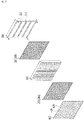
Wie in
Das Gehäuse 100 ist ein Substrat zum Aufnehmen photokatalytischer Kugeln (B) und kann in einem Innenraum photokatalytische Kugeln (B) aufnehmen. Der Innenraum des Gehäuses 100 ist in der Hin- und Her-Richtung geöffnet, um zu ermöglichen, dass Fluid durch ihn hindurchgeht. Beispielsweise kann kontaminierte Luft (A1) in die Vorderseite des Innenraums eingeführt werden und durch die Rückseite des Innenraums hindurchgehen, und wird in diesem Prozess nach außen abgegeben, nachdem sie durch Hydroxyl-Radikale, die durch die photokatalytische Reaktion erzeugt wurden, in gereinigte Luft (A2) umgewandelt worden ist.The
Der Luftstrom kann durch eine separate Vorrichtung, wie etwa ein in
Außerdem kann der Innenraum des Gehäuses 100 in eine Vielzahl von Photokatalysator-Aufnahmeräumen unterteilt werden. Zusätzlich kann eine Vielzahl von photokatalytischen Kugeln (B) in jedem Photokatalysator-Aufnahmeraum aufgenommen werden.In addition, the interior of the
Insbesondere kann gemäß einer Ausführungsform der vorliegenden Erfindung, im Unterschied zu dem Photokatalysator von
Verglichen mit dem Photokatalysator von
Außerdem ist der Photokatalysator von
Die spezifische Struktur des Photokatalysator-Aufnahmeraums, in dem die photokatalytischen Kugeln (B) aufgenommen sind, wird im Detail unter Bezugnahme auf
Die Abdeckungseinheit 200, die ein Element zum Verhindern ist, dass die photokatalytischen Kugeln (B) von dem Photokatalysator-Aufnahmeraum getrennt werden, kann an der Vorderseite und der Rückseite des Gehäuses 100 angebracht sein. Beispielsweise kann die Abdeckungseinheit 200 eine erste Abdeckungseinheit (210), die an der Vorderseite des Gehäuses 100 angebracht ist, und eine zweite Abdeckungseinheit (220) umfassen, die an der Rückseite des Gehäuses 100 angebracht ist.The
Andererseits ist eine einzelne Abdeckungseinheit 200, die ein „⊏“-Form aufweist, an dem Gehäuse 100 angebracht, um gleichzeitig die Vorderseite und die Rückseite des Gehäuses 100 abzudecken.On the other hand, a
Die Lichtquelleneinheit 300 ist an der Rückseite des Gehäuses 100 vorgesehen, um Licht zu dem Gehäuse 100 hin einzustrahlen.The
Beispielsweise kann die Lichtquelleneinheit 300 einen Rahmen 310 und eine Lichtemittierungseinheit 320 umfassen. Die Lichtemittierungseinheit 320 ist an dem Rahmen 310 montiert, um Licht zu den photokatalytischen Kugeln (B) hin in dem Photokatalysator-Aufnahmeraum einzustrahlen. Beispielsweise kann die Lichtemittierungseinheit 320 eine Lichtquelle zum Einstrahlen ultravioletter Strahlen sein.For example, the
Beispielsweise kann die Lichtemittierungseinheit 320 eine UV-A-Licht-Lichtquelle sein. Im Unterschied zu einer allgemeinen UV-Lichtquelle, die Licht in einem breiten Wellenlängenbereich emittiert, weist die UV-A-Licht-Lichtquelle einen Vorteil des Senkens von Fertigungskosten des Photokatalysator-Filtermoduls auf, da sie Licht mit einer relativ schmalen Wellenlänge, die für eine photokatalytische Reaktion erforderlich ist, emittiert und Einheitskosten reduziert. Als ein Beispiel kann die UV-A-Licht-Lichtquelle aus Lichtquellen ausgewählt werden, die eine Lebensdauer im Bereich von etwa zwei bis fünf Millionen Stunden aufweisen.For example, the
Zusätzlich können ein oder mehrere Fenster, durch die ein Fluid hindurchgehen kann, in dem Rahmen 310 gebildet sein.Additionally, one or more windows through which fluid can pass may be formed in the
Die Schutzabdeckungseinheit 400 kann vor dem Gehäuse 100 vorgesehen sein. Die Schutzabdeckungseinheit 400 schützt die Rückseitenstruktur vor einer äußeren Einwirkung oder Fremdmaterial und reflektiert gleichzeitig Licht, das durch den Photokatalysator-Aufnahmeraum hindurchgegangen ist, indem es von der Lichtquelleneinheit 300 eingestrahlt wird. Die Merkmale der Schutzabdeckungseinheit 400 werden im Detail unter Bezugnahme auf
Wie in
Als ein Beispiel kann der Innenraum des Gehäuses 100 durch eine Unterteilung 110 unterteilt sein. Das heißt, die Unterteilung 110 teilt den Innenraum des Gehäuses 100 auf, um eine Vielzahl von Photokatalysator-Aufnahmeräumen zu bilden.As an example, the interior of the
Gemäß einer Ausführungsform der vorliegenden Erfindung kann die Unterteilung 110 eine Vielzahl von ersten Unterteilungen, die eine sich in einer vertikalen Richtung erstreckende Form aufweisen, und eine Vielzahl von zweiten Unterteilungen umfassen, die eine sich in der lateralen Richtung erstreckende Form aufweisen. Die Vielzahl von ersten Unterteilungen und die Vielzahl von zweiten Unterteilungen können einander überkreuzen, und eine Vielzahl von Photokatalysator-Aufnahmeräumen können gebildet werden.According to an embodiment of the present invention, the
Zusätzlich können photokatalytische Kugeln (B) in jedem Photokatalysator-Aufnahmeraum aufgenommen sein. Gemäß einer Ausführungsform der vorliegenden Erfindung können eine oder mehrere photokatalytische Kugeln (B) in dem einzelnen Photokatalysator-Aufnahmeraum aufgenommen sein.In addition, photocatalyst balls (B) may be accommodated in each photocatalyst accommodating space. According to an embodiment of the present invention, one or more photocatalyst balls (B) may be accommodated in the single photocatalyst accommodating space.
Unterdessen kann, wie in
Wie in
In diesem Fall muss, um die kontaminierte Luft (A1) ausreichend zu sterilisieren, die kontaminierte Luft (A1) für einen vorgegebenen Zeitraum oder länger in der Nähe des Photokatalysator-Aufnahmeraums bleiben. In anderen Worten muss der Photokatalysator-Aufnahmeraum dazu ausgelegt sein, eine Struktur aufzuweisen, in der die in die Vorderseite eintretende Luft für einen vorgegebenen Zeitraum bleiben kann, bis sie durch den Photokatalysator-Aufnahmeraum hindurchgeht, in dem die photokatalytischen Kugeln (B) aufgenommen sind.In this case, in order to sufficiently sterilize the contaminated air (A1), the contaminated air (A1) needs to stay near the photocatalyst accommodating space for a predetermined period of time or more. In other words, the photocatalyst accommodating space must be designed to have a structure in which the air entering the front side can stay for a predetermined period of time until it passes through the photocatalyst accommodating space in which the photocatalytic balls (B) are accommodated .
Um das Obige zu erzielen, kann der Photokatalysator-Aufnahmeraum eine maximale Breite (W) von 1,2-mal bis dreimal des Durchmessers einer photokatalytische Kugel (B) aufweisen. Außerdem kann der Photokatalysator-Aufnahmeraum eine maximale Höhe (H) von 1,2-mal bis dreimal des Durchmessers einer photokatalytischen Kugel (B) aufweisen. Außerdem kann der Photokatalysator-Aufnahmeraum eine maximale Tiefe (D) von 1,2-mal bis dreimal des Durchmessers einer photokatalytischen Kugel (B) aufweisen. Eine derartige Bedingung soll die Bildung eines Wirbels in dem Photokatalysator-Aufnahmeraum durch Aufnehmen der Vielzahl von photokatalytischen Kugeln (B) in dem Photokatalysator-Aufnahmeraum hervorrufen. Wenn der Wirbel gebildet wird, kann die kontaminierte Luft (A1) effektiv sterilisiert werden, da eine Zeit, in der sie in der Nähe der photokatalytischen Kugeln (B) bleibt, erhöht wird.In order to achieve the above, the photocatalyst accommodating space may have a maximum width (W) of 1.2 to three times the diameter of a photocatalyst ball (B). In addition, the photocatalyst accommodating space may have a maximum height (H) of 1.2 to three times the diameter of a photocatalyst sphere (B). In addition, the photocatalyst accommodating space may have a maximum depth (D) of 1.2 to three times the diameter of a photocatalyst sphere (B). Such a condition is said to cause generation of a vortex in the photocatalyst accommodating space by accommodating the plurality of photocatalytic balls (B) in the photocatalyst accommodating space. When the vortex is formed, the contaminated air (A1) can be effectively sterilized since a time that it stays near the photocatalytic balls (B) is increased.
Zusätzlich kann das Gesamtvolumen der photokatalytischen Kugeln (B), die in dem einzelnen Photokatalysator-Aufnahmeraum aufgenommen sind, 1/2 bis 3/4 des Volumens des einzelnen Photokatalysator-Aufnahmeraums sein. Da die photokatalytische Kugel (B) einen physischen Raum einnimmt, wird, falls zu viele photokatalytische Kugeln (B) in dem einzelnen Photokatalysator-Aufnahmeraum aufgenommen sind, die Strömung des Fluids übermäßig unterdrückt.In addition, the total volume of the photocatalyst balls (B) accommodated in the single photocatalyst accommodating space may be 1/2 to 3/4 of the volume of the single photocatalyst accommodating space. Since the photocatalyst ball (B) occupies a physical space, if too many photocatalyst balls (B) are accommodated in the single photocatalyst accommodating space, the flow of the fluid is excessively suppressed.
Unterdessen ist
Im Detail ist
In der Ausführungsform von
Die Wahrscheinlichkeit, dass die kontaminierte Luft (A1) sterilisiert wird, während sie durch den Photokatalysator-Aufnahmeraum hindurchgeht, kann erhöht werden, wenn die photokatalytische Reaktion in der Vielzahl von photokatalytischen Kugeln (B) gleichmäßig auftritt. Deshalb ist der Abstand zwischen der ersten Abdeckungseinheit 210 und der Lichtemittierungseinheit 320 vorzugsweise 30 mm oder weniger.The possibility that the contaminated air (A1) is sterilized while passing through the photocatalyst accommodating space can be increased when the photocatalytic reaction occurs uniformly in the plurality of photocatalytic balls (B). Therefore, the distance between the
Unterdessen kann, um den Abstand zwischen der ersten Abdeckungseinheit 210 und der Lichtemittierungseinheit 320 bei 30 mm oder weniger aufrechtzuerhalten und die Bedingung von
Die kontaminierte Luft (A1), die durch den Photokatalysator-Aufnahmeraum hindurchgeht, kann ausreichend sterilisiert werden, während eine angemessene Strömungsrate aufrechterhalten wird, wenn die strukturellen Bedingungen des Photokatalysator-Aufnahmeraums und der photokatalytischen Kugel (B), die in
Gemäß einem experimentellen Ergebnis wurden, wenn Luft in einem vorgegebenen Raum 30 Minuten lang in dem Zustand sterilisiert wurde, in dem die Bedingung von
Wie in
Zusätzlich kann die Schutzabdeckungseinheit 400 Licht reflektieren, das von der Lichtquelleneinheit 300 eingestrahlt wurde und durch den Photokatalysator-Aufnahmeraum hindurchgegangen ist. In diesem Fall kann das Licht, das durch die Schutzabdeckungseinheit 400 reflektiert wurde, dem Photokatalysator-Aufnahmeraum vorangehen. Deshalb kann das von der Lichtquelleneinheit 300 eingestrahlte Licht gleichmäßiger in die Vielzahl von Photokatalysator-Aufnahmeräumen gestreut werden. Deshalb kann die photokatalytische Reaktion gleichmäßig in alle Richtungen der Vielzahl von photokatalytischen Kugeln (B) erzeugt werden.In addition, the
Zusätzlich kann die Schutzabdeckungseinheit 400 aus einem Material bestehen, das in der Lage ist, das von der Lichtquelleneinheit 300 emittierte Licht, nämlich ultraviolette Strahlen, zu reflektieren, und eine Haltbarkeit gegenüber ultravioletten Strahlen aufzuweisen. Beispielsweise kann die Schutzabdeckungseinheit 400 aus einem Aluminiummaterial bestehen.In addition, the
Bezugnehmend auf
Außerdem kann die Vielzahl von ersten Gitterrippen 410 and die Vielzahl von zweiten Gitterrippen 420 von der Unterteilung 110 in der Breitenrichtung geneigt sein. Wenn sich beispielsweise die erste Gitterrippe 410 von der vertikalen Richtung schräg nach links erstreckt, erstreckt sich die zweite Gitterrippe 420 von der vertikalen Richtung schräg nach rechts. Das heißt, die Schutzabdeckungseinheit 400 kann in einer Netzform gebildet sein, die diagonal geneigt ist.In addition, the plurality of
Gemäß der vorliegenden Erfindung kann die Schutzabdeckungseinheit 400 die kontaminierte Luft (A1), die in die Vorderseite des Photokatalysator-Filtermoduls eingeführt wurde, in verschiedene Richtungen dispergieren. Das heißt, die Schutzabdeckungseinheit 400 kann die kontaminierte Luft (A1) führen, um in die Vielzahl von Photokatalysator-Aufnahmeräumen dispergiert zu werden.According to the present invention, the
Zusätzlich kann, da die Schutzabdeckungseinheit 400 den Weg der kontaminierten Luft (A1) führt, um von der Hin- und Her-Richtung geneigt zu sein, die Bildung eines Wirbels in der Vielzahl von Photokatalysator-Aufnahmeräumen gefördert werden.In addition, since the
Im Detail ist
Beim Vergleichen der Ausführungsform von
Wie in
In diesem Fall kann die Vielzahl von ersten Gitterrippen 410 und die Vielzahl von zweiten Gitterrippen 420 eine Struktur aufweisen, um die Wahrscheinlichkeit zu erhöhen, dass die vorwärts eingeführte kontaminierte Luft (A1) leicht durch den Photokatalysator-Aufnahmeraum hindurchgeht und das durch die Schutzabdeckungseinheit 400 reflektierte Licht dem Photokatalysator-Aufnahmeraum vorangeht.In this case, the plurality of
Beispielsweise kann die die Vielzahl von ersten Gitterrippen 410 und die Vielzahl von zweiten Gitterrippen 420 derart gebildet sein, dass eine Oberfläche, die entgegengesetzt zu der Richtung ist, die der Lichtquelleneinheit 300 zugewandt ist, konvexer als eine Oberfläche ist, der der Lichtquelleneinheit 300 zugewandt ist.For example, the plurality of
Deshalb wird die in die Vorderseite der Schutzabdeckungseinheit 400 eingeführte Luft geführt, um dem Photokatalysator-Aufnahmeraum entlang der konvexen Oberfläche der ersten Gitterrippe 410 oder der zweiten Gitterrippe 420 zugewandt zu sein, so dass der Luftwiderstand der Schutzabdeckungseinheit 400 minimiert werden kann.Therefore, the air introduced into the front of the
Da die konvexe Oberfläche die Wahrscheinlichkeit erhöht, dass der Weg der kontaminierten Luft (A1), die die erste Gitterrippe 410 oder die zweite Gitterrippe 420 erreicht, der Rückseite vorangeht, kann die Bildung eines Wirbels in der Vielzahl von Photokatalysator-Aufnahmeräumen gefördert werden.Since the convex surface increases the possibility that the route of the contaminated air (A1) reaching the first
Außerdem kann, da das Licht, das durch den Photokatalysator-Aufnahmeraum hindurchgeht, zu der Rückseitenoberfläche der ersten Gitterrippe 410 oder der zweiten Gitterrippe 420, die konkaver als die Vorderseite ist, gestrahlt wird, das durch die Schutzabdeckungseinheit 400 reflektierte Licht mit einer höheren Wahrscheinlichkeit dem Photokatalysator-Aufnahmeraum vorangehen.In addition, since the light passing through the photocatalyst accommodating space is radiated to the rear surface of the first
Als ein weiteres Beispiel kann, wie in
Als ein weiteres Beispiel kann, wie in
Unterdessen kann die Schutzabdeckungseinheit 400 in einem Paar gebildet sein.Meanwhile, the
Beispielsweise kann ein Paar von Schutzabdeckungseinheiten 400 in der Hin- und Her-Richtung gestapelt sein. Beispielsweise können die ersten Gitterrippen 410 einer Schutzabdeckungseinheit 400 und die ersten Gitterrippen 410 der anderen Schutzabdeckungseinheit 400 dazu angeordnet sein, miteinander überkreuzt zu sein.For example, a pair of
Gemäß der vorliegenden Erfindung ermöglicht die Schutzabdeckungseinheit 400, dass von der Vorderseite eingeführte kontaminierte Luft (A1) leicht hindurchgeht, und kann das Licht, das von der Lichtquelleneinheit 300 eingestrahlt wurde und durch den Photokatalysator-Aufnahmeraum hindurchging, mit einer höheren Wahrscheinlichkeit zu dem Photokatalysator-Aufnahmeraum reflektieren.According to the present invention, the
Wie in
Die optische Faser 330 kann in der Form eines Rohrs gebildet sein und kann entlang des Rahmens 310 langgestreckt sein. Beispielsweise kann die optische Faser 330 in einer Form gebildet sein, die sich entlang der Kante des in dem Rahmen 310 gebildeten Fensters erstreckt.The
Zusätzlich kann die Lichtemittierungseinheit 320 Licht in das Innere der optischen Faser 330 einstrahlen. Das in die optische Faser 330 einfallende Licht kann entlang eines optischen Wegs innerhalb der optischen Faser 330 bewegt werden.In addition, the
In diesem Fall kann das sich innerhalb der optischen Faser 330 bewegende Licht die innere Seitenoberfläche der optischen Faser 330 erreichen und etwas von dem die innere Seitenoberfläche erreichendem Licht kann nach außen emittiert werden. Außerdem kann das nach außen emittierte Licht zu dem Photokatalysator-Aufnahmeraum hin eingestrahlt werden. Beispielsweise kann die optische Faser 330 eine seitenemittierende optische Faser 330 sein.In this case, the light moving inside the
Die optische Faser 300 kann das von der Lichtemittierungseinheit 320 emittierte Licht relativ gleichmäßig an die Vielzahl von Photokatalysator-Aufnahmeräumen abgeben, sogar wenn die Anzahl der Lichtemittierungseinheiten 320 klein ist.The
Das heißt, da eine photokatalytische Reaktion in der Vielzahl von photokatalytischen Kugeln (B) durch Verwenden einer kleinen Anzahl von Lichtemittierungseinheiten 320 erzeugt werden kann, kann der Leistungsverbrauch, der zum Antreiben des Photokatalysator-Filtermoduls erforderlich ist, gesenkt werden. Außerdem kann, da die optische Faser 300 dünn ausgebildet werden kann, die Gesamtdicke des photokatalytischen Filtermoduls dünner werden. Beispielsweise kann die Lichtemittierungseinheit 320 eine Laser-Infrarot-Lichtquelle sein.That is, since a photocatalytic reaction can be generated in the plurality of photocatalytic balls (B) by using a small number of light emitting
Zusätzlich kann, obwohl in
In anderen Worten wird, wenn die optische Faser 330 dazu gebildet ist, wie ein Pigtail gerollt zu sein, die Biegeänderungsrate der optischen Faser 330 niedriger, so dass eine Lichtemission an der Seite der optischen Faser 330 relativ gleichmäßig sein kann.In other words, when the
Die obige Beschreibung der vorliegenden Offenbarung ist nur zur Veranschaulichung, und Fachleute verstehen, dass die vorliegende Offenbarung leicht auf unterschiedliche Arten modifiziert werden kann, ohne wesentliche Techniken oder Merkmale der vorliegenden Offenbarung zu ändern. Deshalb sollten die obigen Ausführungsformen als beschreibend, nicht als beschränkend verstanden werden. Beispielsweise kann irgendeine Komponente, die als eine integrierte Form aufweisend beschrieben ist, in einer verteilten Form implementiert werden, und kann irgendeine Komponente, die als eine verteilte Form aufweisend beschrieben ist, auch in einer integrierten Form implementiert sein.The above description of the present disclosure is for illustration only, and those skilled in the art understand that the present disclosure can be easily modified in various ways without changing essential techniques or features of the present disclosure. Therefore, the above embodiments should be taken as illustrative rather than restrictive. For example, any component described as having an integrated form may be implemented in a distributed form, and any component described as having a distributed form may also be implemented in an integrated form.
Der Umfang der vorliegenden Offenbarung ist eher durch die beigefügten Ansprüche definiert als durch die obige Beschreibung, und alle von der Bedeutung, dem Umfang und den Äquivalenten der beigefügten Ansprüche abgeleiteten Änderungen oder Modifikationen sollten als innerhalb des Umfangs der vorliegenden Offenbarung fallend interpretiert werden.The scope of the present disclosure is defined by the appended claims rather than the above description, and any changes or modifications derived from the meaning, scope and equivalents of the appended claims should be interpreted as falling within the scope of the present disclosure.
Ausführungsform der Erfindungembodiment of the invention
Die Konfiguration für die Praxis der Erfindung ist im Zusammenhang mit der besten Ausführungsform beschrieben worden.The configuration for the practice of the invention has been described in connection with the best mode.
Industrielle AnwendbarkeitIndustrial Applicability
Gemäß einer Ausführungsform der vorliegenden Erfindung gibt es ein Photokatalysator-Filtermodul, das eine Struktur aufweist, die in der Lage ist, zu ermöglichen, dass kontaminierte Luft durch sie hindurchgeht, das eine photokatalytische Reaktion gleichmäßig in alle Richtungen einer Vielzahl von photokatalytischen Kugeln, die darin aufgenommen sind, hervorruft und das die photokatalytische Reaktion schnell bewirkt. So kann das Photokatalysator-Filtermodul gemäß einer Ausführungsform der vorliegenden Erfindung verwendet werden, indem es in einem Luftreiniger in verschiedenen Industriestandorten montiert wird, die eine Sterilisation und Reinigung von Luft erfordern.According to an embodiment of the present invention, there is a photocatalyst filter module having a structure capable of allowing contaminated air to pass therethrough, which uniformly induces a photocatalytic reaction in all directions of a plurality of photocatalytic balls disposed therein are ingested, and which causes the photocatalytic reaction to occur rapidly. Thus, the photocatalyst filter module according to an embodiment of the present invention can be used by mounting it in an air cleaner in various industrial sites that require sterilization and purification of air.
Claims (19)
Applications Claiming Priority (3)
| Application Number | Priority Date | Filing Date | Title |
|---|---|---|---|
| KR10-2021-0032775 | 2021-03-12 | ||
| KR1020210032775A KR102351680B1 (en) | 2021-03-12 | 2021-03-12 | Photocatalysts filter module |
| PCT/KR2021/008329 WO2022191362A1 (en) | 2021-03-12 | 2021-07-01 | Photocatalytic filter module |
Publications (1)
| Publication Number | Publication Date |
|---|---|
| DE112021000085T5 true DE112021000085T5 (en) | 2022-12-08 |
Family
ID=79343177
Family Applications (1)
| Application Number | Title | Priority Date | Filing Date |
|---|---|---|---|
| DE112021000085.3T Ceased DE112021000085T5 (en) | 2021-03-12 | 2021-07-01 | PHOTOCATALYST FILTER MODULE |
Country Status (4)
| Country | Link |
|---|---|
| US (1) | US20230135626A1 (en) |
| KR (1) | KR102351680B1 (en) |
| DE (1) | DE112021000085T5 (en) |
| WO (1) | WO2022191362A1 (en) |
Families Citing this family (5)
| Publication number | Priority date | Publication date | Assignee | Title |
|---|---|---|---|---|
| US20240042384A1 (en) * | 2022-08-02 | 2024-02-08 | Bissell Inc. | Air purifier with air treatment basket |
| KR102621349B1 (en) * | 2022-11-26 | 2024-01-04 | 장현실 | Eco-friendly road spray system including gravel filter device |
| KR102939124B1 (en) | 2023-02-27 | 2026-03-12 | 정진호 | Air purification filter with integrated ultraviolet sterilization lamp |
| KR200498759Y1 (en) * | 2023-03-17 | 2025-01-23 | 정창수 | Sterilization aparatus using photocatalyst |
| KR102636485B1 (en) * | 2023-05-15 | 2024-02-15 | (주)에이버츄얼 | Large-area UV-responsive light fusion sterilization catalyst filter |
Family Cites Families (17)
| Publication number | Priority date | Publication date | Assignee | Title |
|---|---|---|---|---|
| US1895642A (en) * | 1925-12-26 | 1933-01-31 | American Air Filter Co | Filter unit |
| US6149717A (en) * | 1997-01-06 | 2000-11-21 | Carrier Corporation | Electronic air cleaner with germicidal lamp |
| JP2001187124A (en) * | 1999-12-28 | 2001-07-10 | Toshiba Lighting & Technology Corp | Deodorizer and refrigerator |
| JP2002000707A (en) * | 2000-06-22 | 2002-01-08 | Anzai Kantetsu:Kk | Deodorizing and cleaning element, deodorizing and decontaminating unit using the same, and deodorizing and cleaning system using the same |
| KR100445778B1 (en) * | 2001-07-23 | 2004-08-25 | 주식회사 엔비오 | Photocatalyic deodorization filter for air cleaner using plastic optical fibers |
| KR100669968B1 (en) * | 2005-05-11 | 2007-01-19 | 후지쯔 가부시끼가이샤 | Air filter |
| JP4756269B2 (en) * | 2005-05-23 | 2011-08-24 | 独立行政法人産業技術総合研究所 | Sterilization method |
| KR100750993B1 (en) * | 2006-04-28 | 2007-08-23 | 주식회사 이젠텍 | Photocatalyst Deodorization Filter for Air Cleaner |
| KR101198923B1 (en) * | 2012-10-10 | 2012-11-07 | 주식회사 랩죤 | Nano composite filter, And manufacturing method of thereof, And air purification system using thereof |
| KR20160039073A (en) * | 2014-09-30 | 2016-04-08 | 서울바이오시스 주식회사 | A Photocatalytic Ball Filter and a Air Cleaning System thereof |
| KR20170026966A (en) * | 2015-08-31 | 2017-03-09 | 서울시립대학교 산학협력단 | Photocatalyst beads, Filter having the photocatalyst beads, and method of fabricating the same |
| KR102477937B1 (en) * | 2016-10-19 | 2022-12-15 | 삼성전자주식회사 | Photocatalyst filter and air conditioner including photocatalytic filter |
| US10722605B2 (en) * | 2016-10-19 | 2020-07-28 | Samsung Electronics Co., Ltd. | Photocatalyst filter and air conditioner including the same |
| KR102629959B1 (en) * | 2017-01-24 | 2024-01-31 | 삼성전자주식회사 | Electronic apparatus comprising photocatalytic filter |
| JP6317495B1 (en) * | 2017-03-08 | 2018-04-25 | 日機装株式会社 | Air purifier |
| KR102627891B1 (en) * | 2018-01-22 | 2024-01-23 | 서울바이오시스 주식회사 | Deodorizing module and exsiccating device including the same |
| KR20190090959A (en) * | 2018-01-26 | 2019-08-05 | 서울바이오시스 주식회사 | Fluid treatment device |
-
2021
- 2021-03-12 KR KR1020210032775A patent/KR102351680B1/en not_active Expired - Fee Related
- 2021-07-01 US US17/634,227 patent/US20230135626A1/en not_active Abandoned
- 2021-07-01 DE DE112021000085.3T patent/DE112021000085T5/en not_active Ceased
- 2021-07-01 WO PCT/KR2021/008329 patent/WO2022191362A1/en not_active Ceased
Also Published As
| Publication number | Publication date |
|---|---|
| WO2022191362A1 (en) | 2022-09-15 |
| KR102351680B1 (en) | 2022-01-14 |
| US20230135626A1 (en) | 2023-05-04 |
Similar Documents
| Publication | Publication Date | Title |
|---|---|---|
| DE112021000085T5 (en) | PHOTOCATALYST FILTER MODULE | |
| DE102014012870A1 (en) | Air purifier using ultraviolet rays | |
| EP3411087B1 (en) | Air purification device | |
| DE102020002707A1 (en) | Disinfection of air with the help of UVC laser beams | |
| EP3531012B9 (en) | Lighting device for motor vehicles with a rod-like light guide | |
| DE102020119225B3 (en) | Device for disinfecting indoor air | |
| DE102020126096B4 (en) | DEVICE FOR CLEANING AIR | |
| WO2024056429A1 (en) | Optical device for disinfecting upper air layers in a room | |
| DE102020003124A1 (en) | Virus protection device for an air flow / ventilation device or ventilation system or air conditioning system | |
| DE102021130826B4 (en) | Air treatment device | |
| EP1541179A1 (en) | Sterilising apparatus | |
| DE102004008296A1 (en) | Headlamp lens for a motor vehicle has a body for light to pass through with Fresnel lenses and channels opposite a source of light | |
| WO2014174022A1 (en) | Arrangement for light output comprising an led light source and a reflector | |
| DE102022101898A1 (en) | Sterilization device, air filter and filter system | |
| DE2225969A1 (en) | LIGHT REFURBISHING GRATING | |
| EP4035697A1 (en) | Method and device for disinfecting and sterilizing air | |
| EP3338812A1 (en) | Method and device for cleaning a medical product | |
| EP1685348B2 (en) | Lamp comprising a transparent light-emerging element | |
| DE102021105374A1 (en) | air treatment apparatus | |
| DE202020105495U1 (en) | Air purification device and use of such | |
| DE112022006593T5 (en) | DEVICE FOR AIR TREATMENT BY MEANS OF UV RADIATION AND ARRANGEMENT COMPRISING THIS DEVICE | |
| DE102021000419B4 (en) | Aerosol protection device and aerosol protection arrangement | |
| EP4175854B1 (en) | Storage compartment for a vehicle | |
| DE102022100598B4 (en) | insulator | |
| DE102022107654A1 (en) | Device for ventilation and temperature control of a room |
Legal Events
| Date | Code | Title | Description |
|---|---|---|---|
| R012 | Request for examination validly filed | ||
| R081 | Change of applicant/patentee |
Owner name: WE.RB CO., LTD., GIMPO-SI, KR Free format text: FORMER OWNER: WE.RB CO., LTD., GIMPO-SI, GYEONGGI-DO, KR |
|
| R002 | Refusal decision in examination/registration proceedings | ||
| R003 | Refusal decision now final |