DE112020005985T5 - Photoacoustic multipoint measuring device - Google Patents
Photoacoustic multipoint measuring device Download PDFInfo
- Publication number
- DE112020005985T5 DE112020005985T5 DE112020005985.5T DE112020005985T DE112020005985T5 DE 112020005985 T5 DE112020005985 T5 DE 112020005985T5 DE 112020005985 T DE112020005985 T DE 112020005985T DE 112020005985 T5 DE112020005985 T5 DE 112020005985T5
- Authority
- DE
- Germany
- Prior art keywords
- sample
- matrix
- pump
- probe
- pulse
- Prior art date
- Legal status (The legal status is an assumption and is not a legal conclusion. Google has not performed a legal analysis and makes no representation as to the accuracy of the status listed.)
- Pending
Links
- 239000000523 sample Substances 0.000 claims abstract description 132
- 238000000034 method Methods 0.000 claims abstract description 19
- 238000012512 characterization method Methods 0.000 claims abstract description 18
- 230000001066 destructive effect Effects 0.000 claims abstract description 9
- 230000005284 excitation Effects 0.000 claims abstract description 9
- 238000001208 nuclear magnetic resonance pulse sequence Methods 0.000 claims abstract description 3
- 239000011159 matrix material Substances 0.000 claims description 59
- 238000012360 testing method Methods 0.000 claims description 29
- 230000009466 transformation Effects 0.000 claims description 11
- 230000003993 interaction Effects 0.000 claims description 10
- 238000012545 processing Methods 0.000 claims description 9
- 238000009826 distribution Methods 0.000 claims description 8
- 238000013507 mapping Methods 0.000 claims description 8
- 230000006870 function Effects 0.000 claims description 5
- 238000007493 shaping process Methods 0.000 claims description 5
- 239000011247 coating layer Substances 0.000 claims description 2
- 238000005457 optimization Methods 0.000 claims 1
- 238000004458 analytical method Methods 0.000 abstract description 3
- 230000003287 optical effect Effects 0.000 description 14
- 238000005259 measurement Methods 0.000 description 12
- 230000004044 response Effects 0.000 description 9
- 238000001514 detection method Methods 0.000 description 8
- 230000001360 synchronised effect Effects 0.000 description 6
- 239000000463 material Substances 0.000 description 4
- 238000012544 monitoring process Methods 0.000 description 4
- 230000003595 spectral effect Effects 0.000 description 4
- 230000035559 beat frequency Effects 0.000 description 3
- 230000008901 benefit Effects 0.000 description 3
- 239000010410 layer Substances 0.000 description 3
- 238000003860 storage Methods 0.000 description 3
- 230000002123 temporal effect Effects 0.000 description 3
- 230000000007 visual effect Effects 0.000 description 3
- 230000005540 biological transmission Effects 0.000 description 2
- 238000006243 chemical reaction Methods 0.000 description 2
- 230000001143 conditioned effect Effects 0.000 description 2
- 230000007547 defect Effects 0.000 description 2
- 230000001934 delay Effects 0.000 description 2
- 238000011161 development Methods 0.000 description 2
- 238000006073 displacement reaction Methods 0.000 description 2
- 230000000694 effects Effects 0.000 description 2
- 238000003384 imaging method Methods 0.000 description 2
- 238000004519 manufacturing process Methods 0.000 description 2
- 239000002105 nanoparticle Substances 0.000 description 2
- 230000000644 propagated effect Effects 0.000 description 2
- 238000005086 pumping Methods 0.000 description 2
- 230000002441 reversible effect Effects 0.000 description 2
- 238000005070 sampling Methods 0.000 description 2
- 239000000126 substance Substances 0.000 description 2
- BUHVIAUBTBOHAG-FOYDDCNASA-N (2r,3r,4s,5r)-2-[6-[[2-(3,5-dimethoxyphenyl)-2-(2-methylphenyl)ethyl]amino]purin-9-yl]-5-(hydroxymethyl)oxolane-3,4-diol Chemical compound COC1=CC(OC)=CC(C(CNC=2C=3N=CN(C=3N=CN=2)[C@H]2[C@@H]([C@H](O)[C@@H](CO)O2)O)C=2C(=CC=CC=2)C)=C1 BUHVIAUBTBOHAG-FOYDDCNASA-N 0.000 description 1
- 206010001497 Agitation Diseases 0.000 description 1
- 241001295925 Gegenes Species 0.000 description 1
- 241001181114 Neta Species 0.000 description 1
- 238000010521 absorption reaction Methods 0.000 description 1
- 239000000853 adhesive Substances 0.000 description 1
- 230000001070 adhesive effect Effects 0.000 description 1
- 230000037007 arousal Effects 0.000 description 1
- 238000003491 array Methods 0.000 description 1
- 230000003750 conditioning effect Effects 0.000 description 1
- 230000003247 decreasing effect Effects 0.000 description 1
- 230000003111 delayed effect Effects 0.000 description 1
- 230000010339 dilation Effects 0.000 description 1
- 239000000284 extract Substances 0.000 description 1
- 238000000605 extraction Methods 0.000 description 1
- 239000011888 foil Substances 0.000 description 1
- 238000010438 heat treatment Methods 0.000 description 1
- 230000002045 lasting effect Effects 0.000 description 1
- 239000007788 liquid Substances 0.000 description 1
- 238000004377 microelectronic Methods 0.000 description 1
- -1 multilayer systems Substances 0.000 description 1
- 239000002086 nanomaterial Substances 0.000 description 1
- 238000001579 optical reflectometry Methods 0.000 description 1
- 230000000737 periodic effect Effects 0.000 description 1
- 230000000704 physical effect Effects 0.000 description 1
- 230000010287 polarization Effects 0.000 description 1
- 238000007781 pre-processing Methods 0.000 description 1
- 238000013139 quantization Methods 0.000 description 1
- 230000006798 recombination Effects 0.000 description 1
- 238000005215 recombination Methods 0.000 description 1
- 238000002310 reflectometry Methods 0.000 description 1
- 230000033764 rhythmic process Effects 0.000 description 1
- 239000007787 solid Substances 0.000 description 1
- 239000000758 substrate Substances 0.000 description 1
- 230000001052 transient effect Effects 0.000 description 1
- 238000009827 uniform distribution Methods 0.000 description 1
- 238000012795 verification Methods 0.000 description 1
Images


Classifications
-
- G—PHYSICS
- G01—MEASURING; TESTING
- G01N—INVESTIGATING OR ANALYSING MATERIALS BY DETERMINING THEIR CHEMICAL OR PHYSICAL PROPERTIES
- G01N21/00—Investigating or analysing materials by the use of optical means, i.e. using sub-millimetre waves, infrared, visible or ultraviolet light
- G01N21/17—Systems in which incident light is modified in accordance with the properties of the material investigated
- G01N21/1702—Systems in which incident light is modified in accordance with the properties of the material investigated with opto-acoustic detection, e.g. for gases or analysing solids
-
- G—PHYSICS
- G01—MEASURING; TESTING
- G01N—INVESTIGATING OR ANALYSING MATERIALS BY DETERMINING THEIR CHEMICAL OR PHYSICAL PROPERTIES
- G01N21/00—Investigating or analysing materials by the use of optical means, i.e. using sub-millimetre waves, infrared, visible or ultraviolet light
- G01N21/17—Systems in which incident light is modified in accordance with the properties of the material investigated
- G01N21/1717—Systems in which incident light is modified in accordance with the properties of the material investigated with a modulation of one or more physical properties of the sample during the optical investigation, e.g. electro-reflectance
-
- G—PHYSICS
- G01—MEASURING; TESTING
- G01N—INVESTIGATING OR ANALYSING MATERIALS BY DETERMINING THEIR CHEMICAL OR PHYSICAL PROPERTIES
- G01N21/00—Investigating or analysing materials by the use of optical means, i.e. using sub-millimetre waves, infrared, visible or ultraviolet light
- G01N21/17—Systems in which incident light is modified in accordance with the properties of the material investigated
- G01N21/41—Refractivity; Phase-affecting properties, e.g. optical path length
- G01N21/45—Refractivity; Phase-affecting properties, e.g. optical path length using interferometric methods; using Schlieren methods
-
- G—PHYSICS
- G01—MEASURING; TESTING
- G01N—INVESTIGATING OR ANALYSING MATERIALS BY DETERMINING THEIR CHEMICAL OR PHYSICAL PROPERTIES
- G01N21/00—Investigating or analysing materials by the use of optical means, i.e. using sub-millimetre waves, infrared, visible or ultraviolet light
- G01N21/17—Systems in which incident light is modified in accordance with the properties of the material investigated
- G01N21/1717—Systems in which incident light is modified in accordance with the properties of the material investigated with a modulation of one or more physical properties of the sample during the optical investigation, e.g. electro-reflectance
- G01N2021/1725—Modulation of properties by light, e.g. photoreflectance
-
- G—PHYSICS
- G01—MEASURING; TESTING
- G01N—INVESTIGATING OR ANALYSING MATERIALS BY DETERMINING THEIR CHEMICAL OR PHYSICAL PROPERTIES
- G01N21/00—Investigating or analysing materials by the use of optical means, i.e. using sub-millimetre waves, infrared, visible or ultraviolet light
- G01N21/17—Systems in which incident light is modified in accordance with the properties of the material investigated
- G01N21/1717—Systems in which incident light is modified in accordance with the properties of the material investigated with a modulation of one or more physical properties of the sample during the optical investigation, e.g. electro-reflectance
- G01N2021/1731—Temperature modulation
-
- G—PHYSICS
- G01—MEASURING; TESTING
- G01N—INVESTIGATING OR ANALYSING MATERIALS BY DETERMINING THEIR CHEMICAL OR PHYSICAL PROPERTIES
- G01N21/00—Investigating or analysing materials by the use of optical means, i.e. using sub-millimetre waves, infrared, visible or ultraviolet light
- G01N21/17—Systems in which incident light is modified in accordance with the properties of the material investigated
- G01N21/171—Systems in which incident light is modified in accordance with the properties of the material investigated with calorimetric detection, e.g. with thermal lens detection
-
- G—PHYSICS
- G01—MEASURING; TESTING
- G01N—INVESTIGATING OR ANALYSING MATERIALS BY DETERMINING THEIR CHEMICAL OR PHYSICAL PROPERTIES
- G01N25/00—Investigating or analyzing materials by the use of thermal means
- G01N25/72—Investigating presence of flaws
Landscapes
- Physics & Mathematics (AREA)
- Health & Medical Sciences (AREA)
- Life Sciences & Earth Sciences (AREA)
- Chemical & Material Sciences (AREA)
- Analytical Chemistry (AREA)
- Biochemistry (AREA)
- General Health & Medical Sciences (AREA)
- General Physics & Mathematics (AREA)
- Immunology (AREA)
- Pathology (AREA)
- Investigating Or Analyzing Materials By The Use Of Ultrasonic Waves (AREA)
- Investigating Or Analysing Materials By Optical Means (AREA)
Abstract
Die Erfindung stellt ein Verfahren zur zerstörungsfreien kontaktlosen physikalischen Charakterisierung einer Probe durch wiederholte Erregungen der Oberfläche einer Probe mit einer Impulssequenz vor, die mindestens einen Pumpimpuls eines ersten „Pumplasers“, gefolgt von einer Abfolge von L zeitversetzten Impulsen eines zweiten „Prüflasers“ und die Analyse des von der Oberfläche der Probe gesendeten Strahls durch einen aktivierten Photodetektor umfasst, für den Empfang der von den Photodetektoren während konstanter Zeitfenster bereitgestellten Signale.

Description
Gebiet der Erfindungfield of invention
Die vorliegende Erfindung betrifft das Gebiet der zerstörungsfreien und berührungslosen Charakterisierung einer mechanischen und/oder physikalisch-chemischen Eigenschaft einer Probe durch Analyse der durch eine Interaktion mit Pump- und Prüflaserstrahlen erzeugten akustischen Welle.The present invention relates to the field of non-destructive and non-contact characterization of a mechanical and/or physico-chemical property of a sample by analyzing the acoustic wave generated by interaction with pump and test laser beams.
Das technische Gebiet ist insbesondere das der Photoakustik, vor allem die zerstörungsfreie ultraschnelle Messung der mechanischen, thermischen oder optischen Eigenschaften einer Probe (inertes festes, flüssiges oder gasförmiges Material oder lebende Zelle). Unter ultraschneller Messung ist eine Messung mit einer zeitlichen Auflösung in der Größenordnung der Pikosekunde zu verstehen.The technical field is in particular that of photoacoustics, in particular the non-destructive ultra-fast measurement of the mechanical, thermal or optical properties of a sample (inert solid, liquid or gaseous material or living cell). Ultra-fast measurement means a measurement with a temporal resolution in the order of picoseconds.
Mit der Pump-Prüfimpuls-Methode können ultraschnelle Phänomene im Material wie die Bewegung der Atome oder die Anregung der Elektronen mit Hilfe sehr kurzer Laserimpulse gemessen werden.With the pump test pulse method, ultrafast phenomena in the material such as the movement of atoms or the excitation of electrons can be measured with the help of very short laser pulses.
Zu diesem Zweck wird ein sehr kurzer und intensiver Laserimpuls, der „Pumpimpuls“, zu einer Probe gesendet, um sie anzuregen. Gleich danach wird ein zweiter, schwächerer Impuls, der „Prüfimpuls“, gesendet, wodurch der Erstanregungseffekt gemessen werden kann. Durch Wiederholen und Ändern der Zeit zwischen dem ersten und dem zweiten Impuls kann die Entwicklung der Anregung im Zeitverlauf rekonstruiert und für ein Zeitfenster die im Photodetektor gemessene Lichtintensität oder die Anzahl der vom Photodetektor gezählten Photonen aufgezeichnet werden.For this purpose, a very short and intense laser pulse, the "pump pulse", is sent to a sample to excite it. Immediately afterwards, a second, weaker pulse, the "test pulse", is sent, allowing the initial excitation effect to be measured. By repeating and changing the time between the first and second pulse, the evolution of the excitation over time can be reconstructed and the light intensity measured in the photodetector or the number of photons counted by the photodetector can be recorded for a time window.
Die Absorption eines ersten Laserimpulses, des „Pumpimpulses“, führt zu einer plötzlichen Erwärmung und damit einer Ausdehnung der Oberfläche, die sich je nach Geometrie des untersuchten Objekts entweder in Form eines akustischen Impulses einer Dauer von einigen Pikosekunden fortpflanzt oder Resonanzvibrationen des Systems auslöst. Die akustischen Impulse oder Vibrationen werden mit Hilfe eines zweiten zeitverzögerten Impulses (nur bei einer Homodyne durch optische Methode), dem „Prüfimpuls“, durch die interferometrische Messung der von den transitorischen akustischen Wellen induzierten Änderungen des optischen Reflektivitätskoeffizienten ermittelt.The absorption of a first laser pulse, the "pump pulse", leads to a sudden heating and thus an expansion of the surface, which, depending on the geometry of the object being examined, is propagated either in the form of an acoustic pulse lasting a few picoseconds or triggers resonant vibrations of the system. The acoustic impulses or vibrations are detected using a second time-delayed impulse (only in the case of a homodyne by optical method), the "test pulse", through the interferometric measurement of the changes in the optical reflectivity coefficient induced by the transitory acoustic waves.
Das Gebiet der Pikosekunden-Akustik hat sich in den letzten Jahren entwickelt und die Untersuchung der elastischen Eigenschaften von dünnen Folien, Mehrschichtsystemen, Nanostrukturen und Nanopartikeln, die Detektion von Spannungsphänomenen und Fehlern an Schnittstellen, die Adhäsionsmessung usw. ermöglicht.The field of picosecond acoustics has developed in recent years, enabling the study of elastic properties of thin foils, multilayer systems, nanostructures and nanoparticles, the detection of stress phenomena and defects at interfaces, adhesion measurement, etc.
Die Pikosekundenakustik wurde ebenfalls für die Untersuchung massiver Systeme verwendet. Parallel dazu entwickelten sich industrielle Anwendungen auf dem Gebiet der zerstörungsfreien Beurteilung in der Mikroelektronik, die zur Entwicklung von kommerziellen Messvorrichtungen führten.Picosecond acoustics have also been used to study massive systems. In parallel, industrial applications in the field of non-destructive assessment in microelectronics developed, leading to the development of commercial measuring devices.
Stand der TechnikState of the art
Nach dem Stand der Technik ist der Artikel „Mesurer les proprietes mecaniques de la matiere à l’echelle de nanometres ä l'aide de l'accoustique picosecondes“ PHOTONIQUES N°94, 1. November 2018, Seite 30)33 XP055734848 des Erfinders, der Artikel Allaoua Abbas „Developpement d'un dispositif pompe-sonde heterodyne“ vom 9. Mai 2013 XP055734712 sowie dessen Promotion „Developpement d'un dispositif pompe-sonde heterodyne: application ä l'imagerie en acoustique picoseconde“ bekannt, die von Allaoua Abbas am 9. Mai 2014 verteidigt wurde (https://tel.archives-ouvertes.fr/tel-00988758/document).According to the state of the art, the article "Mesurer les proprietes mecaniques de la matiere à l'echelle de nanometers ä l'aide de l'accoustique picosecondes" PHOTONIQUES N°94, November 1, 2018, page 30)33 XP055734848 by the inventor, the article Allaoua Abbas "Developpement d'un dispositif pompe-sonde heterodyne" of 9 May 2013 XP055734712 and his doctorate "Developpement d'un dispositif pompe-sonde heterodyne: application ä l'imagerie en acoustique picoseconde" known by Allaoua Abbas was defended on May 9, 2014 (https://tel.archives-ouvertes.fr/tel-00988758/document).
Dieses Dokument beschreibt das Funktionsprinzip einer heterodynen Prüfbank. Zwei Pump-Prüf-Impulsfolgen aus verschiedenen Lasern werden kombiniert (OR), bevor sie auf die untersuchte Probe fokussiert werden, von der sie reflektiert und dann mit Hilfe einer geeigneten Optik zu einem Photodetektor gelenkt werden. Die Abweisung des von der Probe verbreiteten Pumpsignals erfolgt entweder mit Hilfe von Polarisatoren, wenn die Polarisationen der Strahlen gekreuzt gehalten wurden, oder mit Hilfe eines interferometrischen Filters, wenn die Wellenlängen des Pump- und Prüfimpulses unterschiedlich genug sind. Alternativ kann ein nicht polarisierender Strahlenteiler verwendet werden.This document describes the functional principle of a heterodyne test bench. Two pump-probe pulse trains from different lasers are combined (OR) before being focused onto the sample under study, from which they are reflected and then directed to a photodetector using appropriate optics. The pump signal propagated by the sample is rejected either by means of polarizers, if the polarizations of the beams have been kept crossed, or by means of an interferometric filter, if the wavelengths of the pump and probe pulses are sufficiently different. Alternatively, a non-polarizing beam splitter can be used.
Die Differenz Δf, bezeichnet als Schwebungsfrequenz, zwischen der Wiederholungsfrequenz der Prüf- und Pumpimpulsfolgen fPrüfung und fPrüfung + Δf bewirkt eine zunehmende Verzögerung der Prüfimpulse im Verhältnis zu den Pumpenimpulsen. Bei jeder Pumpanregung wird die Pump-Prüf-Verzögerung um δhet inkrementiert, deren Wert durch die Gleichung gegeben ist:![]()
wobei TPrüfung und TPumpe jeweils die Perioden der Prüf- und Pumplaser sind.
δhet kann auch in Abhängigkeit von fPrüfung und Δf ausgedrückt werden mit Hilfe der Formel:
![]()
where T probe and T pump are the periods of the probe and pump lasers, respectively.
δ het can also be expressed in terms of f test and Δf using the formula:
Die Verzögerung nimmt zu, bis die Pump- und Prüfimpulse erneut gleichzeitig auf der Probe auftreffen. Dieser Moment, in dem genau das passiert, wird als Koinzidenz bezeichnet. Die Zeit zwischen zwei Koinzidenzen ist die Zeit, die vom Prüfstrahl benötigt wird, um alle Pump-Prüf-Verzögerungen zu durchqueren. Diese Zeit wird als Schwebungsperiode bezeichnet, und ihr Wert ist der Kehrwert der Schwebungsfrequenz Δf. Das transitorische Signal, das man durch Untersuchung der Schwankung der Prüfintensität erhält, die der Photodetektor während einer Schwebungsperiode ermittelt, entspricht somit der zeitdilatierten Antwort der Probe. Diese Dilatation auf der Zeitskala ist mit dem stroboskopischen Effekt vergleichbar, der auf makroskopischer Ebene beobachtbar ist und der unter bestimmten Bedingungen erlaubt, periodische Bewegungen einzufrieren oder zu verlangsamen.The delay increases until the pump and probe pulses again hit the sample simultaneously. This moment when exactly that happens is called coincidence. The time between two coincidences is the time it takes for the probe beam to traverse all the pump-probe delays. This time is called the beat period and its value is the reciprocal of the beat frequency Δf. The transient signal obtained by examining the variation in probe intensity detected by the photodetector during a beat period thus corresponds to the time-dilated response of the sample. This dilation on the time scale is comparable to the stroboscopic effect observable at the macroscopic level, which under certain conditions allows periodic movements to be frozen or slowed down.
Die Gleichung, die die Zeitskala der dilatierten Zeit Tdilatiert, was der Zeitskala der Erfassungen entspricht, und die Skala der physikalischen Zeit Tphysikalisch verbindet, die der tatsächlichen Dynamik der Probe entspricht, ist:![]()
![]()
Es können zwei Verzögerungen definiert werden:
- • die erste in der dilatierten Zeit ΔThet entspricht der Dauer, die die Koinzidenz und den Moment trennt, in dem der Reflektivitätswert der Prüfung abgelesen wird,
- • die zweite in der physikalischen Zeit δThet entspricht der Dauer zwischen der Prüfung und der vorausgegangenen Erregung durch den Pumpstrahl.
- • the first in the dilated time ΔT het corresponds to the duration separating the coincidence and the moment when the reflectivity value of the test is read,
- • the second in physical time δT het corresponds to the duration between the test and the previous excitation by the pump beam.
Die Interaktion mit dem Material erfolgt durch die Entstehung von Schallwellen mit einem erhöhten Spektralinhalt, was die Charakterisierung von Proben mit Nanometerabmessungen durch einen Photodetektor gestattet. Durch die differentielle Detektion kann die Fluktuation der Stärke des Prüflasers teilweise ausgeschaltet werden. Darüber hinaus wird dadurch das Niveau der mittleren Signale in die Nähe von 0 geführt, so dass man von der minimalen Quantifizierungsschrittweite der Erfassungskarte profitiert.The interaction with the material occurs through the generation of sound waves with increased spectral content, which allows the characterization of samples with nanometer dimensions by a photodetector. The fluctuation in the strength of the test laser can be partially eliminated by the differential detection. In addition, this brings the level of the mean signals close to 0, taking advantage of the minimum quantization step size of the acquisition card.
Diese Promotion unterbreitet ebenfalls eine Lösung für die bildliche Darstellung einer Oberfläche einer Probe durch Kontrolle der relativen Positionen der Brennpunktflecken des Pump- und Prüfstrahls auf der Probe. Durch diese Kontrolle wird der Raum um eine Erregung vernetzbar, so dass die von ihr hervorgerufenen Übergangsphänomene kartographiert werden können.This thesis also proposes a solution for imaging a surface of a sample by controlling the relative positions of the pump and probe beam focal spots on the sample. This control makes the space around an arousal connectable so that the transitional phenomena it produces can be mapped.
Bekannt sind ebenfalls der Artikel Neta TECH „JAX-M1“ Januar 2018 XP055735269 der Antragstellerin sowie das japanische Patent
Bekannt ist ebenfalls das französische Patent
Schließlich ist das amerikanische Patent
Nachteile des Standes der TechnikDisadvantages of the Prior Art
Die nach dem Stand der Technik vorgeschlagene Lösung weist viele Nachteile auf, die aus der Abtastung resultieren, die für die Deflektometrie und die Erzeugung von Oberflächenwellen verwendet wird (Messung der transversen Eigenschaften des Materials).The solution proposed in the prior art has many disadvantages resulting from the scanning used for deflectometry and surface wave generation (measurement of the transverse properties of the material).
Ein erster Nachteil, der in dem Dokument auch zugegeben wird, ist die Schwierigkeit, die Verlagerungen in so hohen Frequenzen zu steuern und dabei die Impulsfolgen und die Photodetektion zu synchronisieren.A first drawback, also acknowledged in the document, is the difficulty of controlling the displacements at such high frequencies while synchronizing the pulse trains and the photodetection.
Ein zweiter Nachteil ist mit den durch diese Abtastungen induzierten Analysezeiten verbunden, die, wie in der Promotion angegeben ist, mehrere Stunden beanspruchen können. Eine derartige Dauer ist mit einer industriellen Anwendung nur schwer kompatibel, wenn es z. B. um die Kontrolle der Probe innerhalb eines Produktionszyklus geht.A second disadvantage is linked to the analysis times induced by these scans, which, as stated in the promotion, can take several hours. Such a duration is difficult to be compatible with an industrial application, e.g. B. the control of the sample within a production cycle.
Eine derartige Dauer ist für die Analyse von Proben mit einer sehr kurzen Lebensdauer schlichtweg nicht praktikabel, wenn es sich z. B. um eine isolierte lebende Zelle handelt, deren Lebensdauer wenige Minuten nicht überschreitet.Such a duration is simply not practical for the analysis of samples with a very short lifetime, e.g. B. is an isolated living cell whose lifespan does not exceed a few minutes.
Schließlich führt die punktuelle Interaktion zu lokalen Informationen, die die mechanischen, chemischen und physikalischen Verbindungen mit den benachbarten lokalen Zonen nicht berücksichtigen und die deswegen einen Typ einer Charakterisierung einer Oberfläche der Probe liefern, der sowohl von der Remanenz der benachbarten Impulse als auch von der Nichtberücksichtigung der allgemeinen Merkmale der analysierten Oberfläche beeinträchtigt ist.Finally, the punctiform interaction leads to local information that does not take into account the mechanical, chemical and physical connections with the neighboring local zones and that therefore provide a type of characterization of a surface of the sample that depends both on the remanence of the neighboring pulses and on the ignorance of the general characteristics of the analyzed surface is affected.
Zusammenfassend gesagt, besteht das Problem für den Fachmann darin, innerhalb von Fristen, die mit operativen Anforderungen wie Einhaltung der Kontrollrhythmen innerhalb einer Produktionslinie, Nichtbeschädigung der Probe unter transitorischen Bedingungen, die für die Messung notwendig sind, Verkürzung der Messzeiten, Erhöhung der Menge der gesammelten Daten kompatibel sind, eine oder zwei Kartographien (1D in einer Dimension oder 2D in zwei Dimensionen) konstruieren zu können, die für die physikalischen (mechanischen, thermischen oder optischen) Eigenschaften unterschiedlicher Proben repräsentativ sind.In summary, the problem for the professional is to manage within deadlines linked to operational needs such as respecting the control rhythms within a production line, not damaging the sample in transitory conditions necessary for the measurement, reducing measurement times, increasing the quantity of collected data are compatible to be able to construct one or two maps (1D in one dimension or 2D in two dimensions) representative of the physical (mechanical, thermal or optical) properties of different samples.
Von der Erfindung bereitgestellte LösungSolution provided by the invention
Um diesen Nachteilen abzuhelfen, betrifft die Erfindung ganz allgemein ein Verfahren zur zerstörungsfreien kontaktlosen physikalischen Charakterisierung einer Probe durch wiederholte Erregungen der Oberfläche einer Probe mit einer Laserimpulssequenz, die mindestens einen Pumpimpuls eines ersten „Pumplasers“, gefolgt von einer Abfolge von L zeitversetzten Impulsen eines zweiten „Prüflasers“ umfasst, und die Analyse des von der Oberfläche der Probe gesendeten Strahls durch einen aktivierten Photodetektor, für den Empfang der von den Photodetektoren während konstanter Zeitfenster bereitgestellten Signale,
dadurch gekennzeichnet, dass
- • die Pump- und Prüfstrahlen eine gleichmäßige räumliche Verteilung vom Typ „Top hat“ in N Dimensionen aufweisen, wobei N gleich eins oder gleich zwei ist,
- • der Detektor aus einer Matrix mit N Dimensionen aus M Photodetektoren besteht, mit M größer als 2,
- • das Verfahren darin besteht, für jede Sequenz eine Matrix MPD aus MxL Werten von Signalen zu registrieren, die von jedem der Photodetektoren vor oder nach dem Prüfimpuls und vor dem nächsten Pumpimpuls bereitgestellt werden, und mindestens eine digitale Verarbeitung auf die Matrix anzuwenden, um eine Kartographie der vom Detektor analysierten Zone der Probe in Form einer Matrix Mcc der Werte des beobachteten physikalischen Merkmals für Q Punkte der analysierten Zone zu erstellen, wobei Q zwischen 1 und M liegt.
characterized in that
- • the pump and probe beams have a uniform spatial distribution of the "top hat" type in N dimensions, where N is equal to one or equal to two,
- • the detector consists of an N-dimensional matrix of M photodetectors, with M greater than 2,
- • the method consists in registering, for each sequence, a matrix M PD of MxL values of signals provided by each of the photodetectors before or after the test pulse and before the next pump pulse, and applying at least one digital processing to the matrix in order to to draw up a map of the zone of the sample analyzed by the detector in the form of a matrix M cc of the values of the observed physical characteristic for Q points of the zone analyzed, where Q is between 1 and M.
Die Dauer der Laserimpulse liegt zwischen der Pikosekunde und der Femtosekunde und vorzugsweise in der Größenordnung des Femtosekunden-Hundertstels.The duration of the laser pulses is between the picosecond and the femtosecond, and preferably of the order of one hundredth of a femtosecond.
Vorzugsweise besteht die digitale Verarbeitung darin, eine Transformationsmatrix MTR auf die Matrix aus MxL Werten von Signalen, die von den Photodetektoren bereitgestellt werden, anzuwenden, um die Matrix Mcc zu bestimmen.Preferably, the digital processing consists in applying a transformation matrix M TR to the matrix of MxL values of signals provided by the photodetectors in order to determine the matrix M cc .
Gemäß einer vorteilhaften Ausführungsform weist das Verfahren Schritte zur Neuberechnung der Matrix MTR durch überwachtes Lernen auf.According to an advantageous embodiment, the method includes steps for recalculating the matrix M TR by supervised learning.
Gemäß einer Variante weist das Verfahren die Registrierung einer Vielzahl von Transformationsmatrizes MTR auf, die jeweils einem besonderen physikalischen Merkmal entsprechen.According to a variant, the method comprises registering a plurality of transformation matrices M TR each corresponding to a particular physical characteristic.
Gemäß einer anderen besonderen Ausführungsform weist das Verfahren ferner einen Schritt zur automatischen Optimierung des Fokus der Optik der „Pump-“- und „Prüfstrahlen“ auf, der darin besteht, eine Sequenz der Variation der Fokussierung und des Messens eines Qualitätsfaktors des von dem Photodetektor erzeugten Signals zu befehlen und die Fokussierung auszuwählen, die einer Maximierung des Qualitätsfaktors für die Gesamtheit der registrierten Werte entspricht.According to another particular embodiment, the method also includes a step for automatically optimizing the focus of the optics of the "pump" and "test" beams, consisting in performing a sequence of varying the focus and measuring a quality factor of that generated by the photodetector signal and to select the focus that corresponds to a maximization of the quality factor for the set of registered values.
Ein anderer Modus ist das Messen mit einem punktuellen Pumpstrahl, der auf die Prüflinie zentriert ist oder nicht, um Oberflächenwellenerfassungen zu ermöglichen.Another mode is measuring with a point pump beam, centered or not on the test line, to allow surface wave detections.
Die Erfindung betrifft in zweiter Linie eine Ausrüstung zur zerstörungsfreien und kontaktlosen physikalischen Charakterisierung einer Probe, die zwei Laserimpulsquellen für das Senden von jeweils einem „Pumpstrahl“ und einem „Prüfstrahl“ aufweist, sowie einen Detektor, dadurch gekennzeichnet, dass sie ferner mindestens eine Formgebungsvorrichtung eines Strahls für die Umwandlung der Verteilung der Pump- und Prüfstrahlen in eine gleichmäßige räumliche Verteilung vom Typ „Top hat“ in N Dimensionen aufweist, wobei N gleich eins oder gleich zwei ist, und dass der Detektor aus einer Matrix mit N Dimensionen aus M Photodetektoren besteht, die jeweils die Anzahl der Photonen vor und nach dem Prüfimpuls und vor dem nächsten Pumpimpuls messen, mit M größer als 2.The invention relates secondarily to equipment for the non-destructive and contactless physical characterization of a sample, comprising two sources of laser pulses for emitting a "pump beam" and a "probe beam" respectively, and a detector, characterized in that it also comprises at least one shaping device of a beam for converting the distribution of the pump and probe beams into a uniform spatial distribution of the "top hat" type in N dimensions, where N is equal to one or two, and that the detector consists of an N-dimensional matrix of M photodetectors , which respectively measure the number of photons before and after the test pulse and before the next pump pulse, with M greater than 2.
Gemäß einer ersten Variante sind die Pump- und Prüfstrahlen in der Interaktionszone mit der Probe koaxial.According to a first variant, the pump and probe beams are coaxial in the zone of interaction with the sample.
Gemäß einer zweiten Variante ist der Pumpstrahl senkrecht zur Ebene der Interaktionszone mit der Probe und der Prüfstrahl bildet einen Winkel unterschiedlich von 90° mit der Interaktionszone mit der Probe.According to a second variant, the pumping beam is perpendicular to the plane of the zone of interaction with the sample and the probe beam forms an angle other than 90° with the zone of interaction with the sample.
Gemäß einer besonderen Umsetzungsform weist die erfindungsgemäße Ausrüstung einen Rechner auf, um die Registrierung für jede Sequenz einer Matrix MPD aus MxL Werten von Signalen zu steuern, die von den Photodetektoren bereitgestellt werden und um mindestens eine digitale Verarbeitung auf die Matrix anzuwenden, um eine Kartographie der von dem Detektor analysierten Zone der Probe in Form einer Matrix Mcc der Werte des beobachteten physikalischen Merkmals für Q Punkte der analysierten Zone, wobei Q zwischen 1 und M liegt, in Abhängigkeit von mindestens einer in einem Informatikspeicher gespeicherten Transformationsmatrix zu erstellen.According to a particular embodiment, the equipment according to the invention comprises a computer to control the registration for each sequence of a matrix M PD of MxL values of signals provided by the photodetectors and to apply at least one digital processing to the matrix to obtain a mapping of the zone of the sample analyzed by the detector in the form of a matrix M cc of values of the observed physical characteristic for Q points of the analyzed zone, where Q is between 1 and M, as a function of at least one transformation matrix stored in a computer memory.
Die Erfindung betrifft in dritter Linie einen Informatikspeicherträger für die Personalisierung einer Ausrüstung zur physikalischen Charakterisierung, aufweisend eine Registrierung einer digitalen Transformationsmatrix MTR auf der Matrix aus MxL Werten von Signalen, die von den Photodetektoren bereitgestellt wurden, um die Matrix Mcc zu bestimmen.The invention relates, thirdly, to a computer storage medium for personalizing physical characterization equipment, comprising registration of a digital transformation matrix M TR on the matrix of MxL values of signals provided by the photodetectors in order to determine the matrix M cc .
In vierter Linie betrifft die Erfindung die Anwendung des obigen Verfahrens für die Kartographie in N Dimensionen, mit N gleich 1 oder 2,
- - der Dicke einer Überzugsschicht einer Probe, insbesondere von lichtdichten, halbtransparenten und transparenten Dünnschichten,
- - des Young-Moduls einer Probe,
- - der Adhäsionskraft einer Probe,
- - des kristallinen Zustands einer Probe,
- - der optischen Kombination der von einer optischen Kamera mit der photoakustischen Bildgebung gewonnenen Bilder.
- - the thickness of a coating layer of a sample, in particular of light-tight, semi-transparent and transparent thin layers,
- - the Young's modulus of a sample,
- - the adhesive force of a sample,
- - the crystalline state of a sample,
- - the optical combination of the images obtained by an optical camera with photoacoustic imaging.
Detaillierte Beschreibung einer nicht beschränkenden Ausführungsform der ErfindungDetailed description of a non-limiting embodiment of the invention
Weitere Merkmale und Vorteile der Erfindung ergeben sich aus der Lektüre der folgenden detaillierten Beschreibung, die ein nicht beschränkendes Beispiel darstellt und sich auf die Zeichnungen in der Anlage bezieht, von denen:
- [
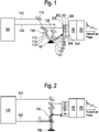
1 ] die1 eine schematische Ansicht des Messsystems ist, - [
2 ] die2 eine schematische Ansicht einer besonderen Konfiguration normaler Inzidenz darstellt, - [
3 ] die3 eine detaillierte schematische Ansicht des Matrix-Photodetektors ist, - [
4 ] die4 eine schematische Ansicht einer Matrix photosensibler Elemente ist, - [
5 ] die5 eine schematische Ansicht des Monitorings des Photodetektors ist.
- [
1 ] the1 is a schematic view of the measurement system, - [
2 ] the2 represents a schematic view of a particular configuration of normal incidence, - [
3 ] the3 is a detailed schematic view of the matrix photodetector, - [
4 ] the4 is a schematic view of a matrix of photosensitive elements, - [
5 ] the5 Figure 12 is a schematic view of the photodetector monitoring.
Allgemeine Prinzipien der ErfindungGeneral principles of the invention
Die Erfindung kombiniert die Verwendung eines Pumpstrahls für die Erregung und eines Prüfstrahls für die Detektion, die von einem synchronen oder asynchronen System mit einer Formgebungsvorrichtung der Strahlen linear oder in quadratischer Matrix erzeugt werden, dann eines Erfassungsmittels des Prüfstrahls vor und nach Störung durch die Probe. Die Erfassung erfolgt durch Diskretisierung des Prüfsignals in n Punkte durch den Photodetektor mit Elementematrix mit Subtraktion des Signals nach Störung durch das Signal vor der Störung, dann durch Digitalisierung des Differentialsignals und die zeitabhängige Wiederherstellung der Antwort der Probe.The invention combines the use of a pump beam for excitation and a probe beam for detection, generated by a synchronous or asynchronous system with a linear or square matrix beam shaping device, then a probe beam detection means before and after disturbance by the sample. The acquisition is made by discretizing the test signal into n points by the photodetector with element matrix, subtracting the signal after the disturbance by the signal before the disturbance, then digitizing the differential signal and restoring the response of the sample over time.
Die Kartographieausrüstung eines physikalischen Merkmals einer Probe gemäß der Erfindung, die als Beispiel beschrieben wird, umfasst ein System (100) mit zwei Laserquellen, die zwei Strahlen (110, 120), einen Pumpstrahl (120) und einen Prüfstrahl (110), erzeugen, die zeitlich versetzt sind und deren Verzögerung einstellbar ist.The mapping equipment of a physical feature of a sample according to the invention, described as an example, comprises a system (100) with two laser sources that generate two beams (110, 120), a pump beam (120) and a probe beam (110), which are offset in time and whose delay is adjustable.
Der Pumpstrahl (120) weist einen linearen oder Quadratmatrix-Formfaktor mit nicht Gaußscher Form auf („top hat beam“).The pump beam (120) has a non-Gaussian linear or square matrix form factor ("top hat beam").
Der Prüfstrahl (110) weist einen linearen oder Quadratmatrix-Formfaktor auf, der mit dem des Pumpstrahls identisch ist.The probe beam (110) has a linear or square matrix form factor identical to that of the pump beam.
Ein Strahl vom Typ „top hat“ weist in einer runden Scheibe eine nahezu gleichmäßige Fluenz (Energiedichte) auf. Er wird im Allgemeinen von diffraktiven optischen Elementen ausgehend von einem Gaußschen Strahl gebildet. Er kann durch Kombination eines Strahlprofilers („Laser beam profiler“) mit einem Pikosekundenlaser oder einem Femtosekundenlaser erhalten werden.A top hat beam has a nearly uniform fluence (energy density) in a circular disk. It is generally made up of diffractive optical elements based on a Gaussian beam. It can be obtained by combining a laser beam profiler with a picosecond laser or a femtosecond laser.
Das System weist ferner einen Differential-Photodetektor (200) mit Matrix (201 bis 205) aus linearen Elementen oder in Quadratmatrixform auf, der an jedem seiner Punkte die Differenz der Signale vor und nach der Störung des auf die Probe einfallenden Prüfstrahls misst. Es erlaubt eventuell als Variante die Ausgabe jeweiliger Mittelwerte der Hin- und Rücksignale, um die jeweiligen Mittelwerte der Hin- und Rücksignale an einem einzigen Referenzwert abzugleichen. Die von den Elementen (201 bis 205) ausgegebenen elektrischen Signale werden an eine Vorverarbeitungsschaltung (210) und danach an einen Analog-Digital-Digitizer (210) weitergeleitet, der die vom Photodetektor (200) gemessenen Antwortsignale speichert.The system also includes a differential photodetector (200) with a matrix (201 to 205) of linear elements or in square matrix form, which measures at each of its points the difference in the signals before and after the perturbation of the probe beam incident on the sample. It may, as a variant, allow the output of respective mean values of the forward and reverse signals in order to align the respective mean values of the forward and reverse signals with a single reference value. Those of the elements (201 bis 205) output electrical signals are forwarded to a pre-processing circuit (210) and then to an analog-to-digital digitizer (210) which stores the response signals measured by the photodetector (200).
Eine bevorzugte Konfiguration, die von der
In diesem Fall müssen einige optische Elemente hinzugefügt werden.In this case, some visual elements need to be added.
Gleichermaßen ist es notwendig, ein optisches Element hinzuzufügen, das die Rekombination der Strahlen untereinander erlaubt, wenn der Winkel zwischen dem Prüfstrahl (121 bis 123) und dem Pumpstrahl (111 bis 113) 0° beträgt.It is also necessary to add an optical element that allows the beams to recombine when the angle between the probe beam (121 to 123) and the pump beam (111 to 113) is 0°.
Das System besteht aus einer synchronen oder asynchronen Vorrichtung (100), die erlaubt, zwei zeitversetzten Laserimpulsstrahlen (110, 120), einen Prüfstrahl (110) und einen Pumpstrahl (120), zu erzeugen. Die Wellenlängen der Strahlen sind unabhängig; für den Prüfstrahl (110) liegen die Wellenlängen innerhalb des Spektralbereichs des Photodetektors (200).The system consists of a synchronous or asynchronous device (100) that allows to generate two time-shifted laser pulse beams (110, 120), a probe beam (110) and a pump beam (120). The wavelengths of the rays are independent; for the test beam (110), the wavelengths are within the spectral range of the photodetector (200).
Der von einer synchronen oder asynchronen Vorrichtung ausgehende Pumpstrahl (120) gelangt in eine optische Formgebungsvorrichtung (125) des Strahls (120). Am Ausgang der Vorrichtung hat der Strahl eine Form, die an die Sensormatrix des Photodetektors angepasst ist und verfügt über eine gleichmäßige Verteilung der Energie auf seiner gesamten Oberfläche (so genannte „top hat-Form“ des Signals).The pumping beam (120), coming from a synchronous or asynchronous device, enters an optical device (125) for shaping the beam (120). At the output of the device, the beam has a shape adapted to the sensor array of the photodetector and has an even distribution of energy over its entire surface (the so-called “top hat” signal shape).
Der von einer synchronen oder asynchronen Vorrichtung (100) ausgehende Prüfstrahl (110) gelangt in eine Entnahmeoptik, die einen Teil der Leistung entnimmt und in eine der Matrizes der Elemente des Differentialphotodetektors (200) mit Elementemaxtrix (201 bis 205) sendet. Der Prüfstrahl durchquert zuerst eine optische Formgebungsvorrichtung (115) des Strahls. Am Ausgang der Vorrichtung hat der Strahl eine Form, die an die Sensormatrix des Photodetektors (200) angepasst ist und verfügt über eine gleichmäßige Verteilung der Energie auf seiner gesamten Oberfläche (so genannte „top hat-Form“ des Signals).The probe beam (110) coming from a synchronous or asynchronous device (100) enters a sampling optics which extracts part of the power and sends it into one of the arrays of elements of the differential photodetector (200) with a matrix of elements (201 to 205). The test beam first passes through an optical beam shaping device (115). At the output of the device, the beam has a shape adapted to the sensor matrix of the photodetector (200) and has a uniform distribution of energy over its entire surface (the so-called “top hat shape” of the signal).
Dann verläuft der Prüfstrahl bei einer Konfiguration mit einem normalen Einfall des Prüfstrahls (110) auf die Probe (150), die auf der
Dann, bei einem Winkel von 0° zwischen dem Pumpstrahl (120) und dem Prüfstrahl (110), werden die Strahlen in einer Rekombinationsoptik rekombiniert, wodurch sie eine einzige Ausrichtung auf die Probe (150) erhalten.Then, at an angle of 0° between the pump beam (120) and the probe beam (110), the beams are recombined in recombination optics, giving them a single orientation on the sample (150).
Schließlich werden die beiden Strahlen (110, 120) mit einer optischen Fokussierungsvorrichtung auf die Probe fokussiert. Bei einer Konfiguration mit nicht normalem Einfall des Prüfstrahls auf die Probe durchquert der Prüfstrahl zwei verschiedene optischen Fokussierungsvorrichtungen, wobei, weil die Bahnen vor und nach der Probe nicht ähnlich sind, die halbreflektierende Optik in dieser Konfiguration nicht verwendet wird.Finally, the two beams (110, 120) are focused onto the sample with an optical focusing device. In a configuration with non-normal incidence of the probe beam on the sample, the probe beam traverses two different focusing optics, and since the trajectories before and after the sample are not similar, the semi-reflective optics are not used in this configuration.
Der von der Probe (150) reflektierte oder übertragene Prüfstrahl (151 bis 153) wird dann in den Differentialphotodetektor (200) mit Elementematrix (201 bis 205) eingeleitet. Die Elementematrix (201 bis 205) des Photodetektors (200) diskretisiert das Signal in n Signale.The probe beam (151-153) reflected or transmitted from the sample (150) is then introduced into the differential photodetector (200) with element matrix (201-205). The element matrix (201 to 205) of the photodetector (200) discretizes the signal into n signals.
Danach werden diese Signale vom vor der Reflexion oder Übertragung des Prüfstrahls auf die Probe gemessenen Prüfsignal subtrahiert. Die Signale werden konditioniert und danach von dem Mehrweg-A/D-Digitizer (220) digitalisiert. Zusätzlich wird der Digitizer (220) mit den Laserquellen (100) synchronisiert, um eine zeitliche Rekonstruktion der n Antworten der Probe (150) durch eine digitale Verarbeitung der Messungen zu erlauben.Then these signals are subtracted from the test signal measured before reflection or transmission of the test beam onto the sample. The signals are conditioned and then digitized by the multipath A/D digitizer (220). In addition, the digitizer (220) is synchronized with the laser sources (100) to allow a temporal reconstruction of the n responses of the sample (150) through digital processing of the measurements.
Bei einem normalen Einfall des Prüfwegs auf die Probe (150) wird der von der Probe (150) reflektierte oder übertragene Prüfstrahl (151 bis 153) von der halbreflektierenden Optik im Differentialphotodetektor (200) mit Elementematrix reflektiert. Die Elementematrix (201 bis 205) des Photodetektors diskretisiert das Signal in n Signale. Danach werden diese Signale vom vor der Reflexion oder Übertragung des Prüfstrahls auf die Probe (150) gemessenen Prüfsignal subtrahiert. Die Signale werden konditioniert und danach von dem Mehrweg-A/D-Digitizer (220) digitalisiert. Zusätzlich wird der Digitizer mit den Laserquellen synchronisiert, um eine zeitliche Rekonstruktion der n Antworten der Probe durch eine digitale Verarbeitung der Messungen zu erlauben. Der Differential-Photodetektor (200) mit Elementematrix (201 bis 205) besteht aus einer Matrix photosensibler Elemente, die bis zu 64 Elemente umfassen kann, die in einer Linie verteilt und im Quadrat 8x8 angeordnet sind. Die Spektralantwort dieser Photoelemente (201 bis 205) deckt eine Spektralband von 190 bis 1700 nm ab. Der Photodetektor erfüllt die folgenden Aufgaben:
- - Strom/Spannungs-Konversion: Mit dieser Funktion (Transimpedanzmontage) können schwache Ströme, die von den photosensiblen Elementen erzeugt werden, in eine nutzbare Spannung umgewandelt werden. Es gibt ebenso viele Strom/Spannungs-Konversionmodule wie photosensible Elemente.
- - Subtraktion: Mit dieser Funktion kann das Nutzsignal zurückgewonnen werden, d. h. die Antwort der Probe durch Ermittlung der Differenz zwischen dem Signal vor der Probe und den Signalen nach der Probe, wobei nur die von der Probe erzeugten Störungen im Signal verbleiben.
- - Signalkonditionierung: formt die Signale vor der Übernahme durch den Digitizer.
- - Current/Voltage Conversion: This function (transimpedance montage) allows weak currents generated by the photosensitive elements to be converted into a usable voltage. There are as many current/voltage conversion modules as there are photosensitive elements.
- - Subtraction: this function allows to recover the useful signal, ie the response of the sample by determining the difference between the signal before the sample and the signals after the sample, leaving only the noise generated by the sample in the signal.
- - Signal conditioning: shapes the signals before they are taken over by the digitizer.
Der Prüfstrahl (110) und der Pumpstrahl (120) können auf der Probe (150) räumlich versetzt sein, um transverse physikalische Phänomene zu messen.The probe beam (110) and the pump beam (120) can be spatially offset on the sample (150) to measure transverse physical phenomena.
Das Scannersystem kann aus zwei beweglichen Spiegeln oder zwei Linsen bestehen, von denen das erste Element im Verhältnis zum zweiten dezentriert ist.The scanner system can consist of two moveable mirrors or two lenses, the first element of which is decentered in relation to the second.
Photodetektorphotodetector
Die
Der Matrix-Photodetektor (200) kann mit Monitoring-Wegen der optischen Leistungen ausgestattet sein, die erlauben, die mittlere optische Leistung des Prüfstrahls vor und nach der Probe zu visualisieren, um die Differentialwege des Detektors auszubalancieren und die Signale zu optimieren. Der Vorteil der linearen/quadratischen Sensoren besteht darin, dass die Elemente eine gemeinsame Kathode haben.The matrix photodetector (200) can be equipped with optical power monitoring paths that allow to visualize the average optical power of the probe beam before and after the sample, in order to balance the detector differential paths and to optimize the signals. The advantage of the linear/square sensors is that the elements share a common cathode.
Der Strom, der die Kathode durchquert, ist die Summe aller Ströme, die von jedem photosensiblen Element (201 bis 205) erzeugt werden. Der Strom, der den Widerstand R (206) durchquert, erzeugt an seinen Klemmen eine Spannung. Diese Spannung wird mit Hilfe eines Verstärkers (207) verstärkt, um eine Spannung zu erhalten, die zur optischen Leistung auf dem linearen Sensor proportional ist. Damit ist für den linearen/quadratischen Sensor ein einziges Monitoring ausreichend.The current crossing the cathode is the sum of all currents generated by each photosensitive element (201 to 205). The current traversing the resistor R (206) creates a voltage across its terminals. This voltage is amplified using an amplifier (207) to obtain a voltage proportional to the optical power on the linear sensor. A single monitoring is therefore sufficient for the linear/square sensor.
Der Photodetektor (200) ist mit einer Matrix aus n photosensiblen Elementen auf dem Rückweg von der Probe und mit einem einzigen photosensiblen Element oder einer Matrix aus n Elementen auf dem Entnahmeweg vor der Probe ausgestattet. Die erzeugten Ströme werden dann, vor Feststellung der Differenz zwischen den Signalen, in Spannung umgewandelt.The photodetector (200) is equipped with a matrix of n photosensitive elements on the return path from the sample and with a single photosensitive element or a matrix of n elements on the extraction path before the sample. The generated currents are then converted to voltage before determining the difference between the signals.
Die Signale können am Ausgang aus dem Photodetektor multiplexiert werden, um die Anzahl der Wege des Digitizer zu begrenzen.The signals may be multiplexed at the output of the photodetector to limit the number of digitizer paths.
Signalverarbeitungsignal processing
Die digitalisierten Signale werden in einer Tabelle gespeichert, die aus Werten von jedem der Elemente (201 bis 205) für die unterschiedlichen Momente der Prüfimpulse besteht, die in Form mehrerer, vom Photodetektor gemessener Lichtstärkekurven oder der Anzahl der Photonen, die vom Photodetektor in Bezug auf die Zeit gezählt wurden, dargestellt sind. Sie stellen einen maximalen Wert dar, der dem Versatz von Null zwischen dem Pumpimpuls und dem ersten Prüfimpuls entspricht, und danach im Allgemeinen fallende Werte.The digitized signals are stored in a table consisting of values of each of the elements (201 to 205) for the different moments of the test pulses, expressed in the form of several light intensity curves measured by the photodetector or the number of photons detected by the photodetector in relation to the times were counted are shown. They represent a maximum value corresponding to the zero offset between the pump pulse and the first test pulse, and generally decreasing values thereafter.
Diese Kurven werden verarbeitet, um daraus charakteristische Informationen zu extrahieren, wie z. B. einzelne Punkte oder die Schräglage bestimmter Segmente.These curves are processed to extract characteristic information, such as B. individual points or the inclination of certain segments.
Diese digitale Matrix wird von einer Transformationsmatrix verarbeitet, die digitale Werten aus dem Photodetektor (200) mit Werten des untersuchten physikalischen Merkmals kombiniert. Diese Transformationsmatrix kann empirisch oder durch überwachtes Lernen konstruiert sein. Sie kann regelmäßig in Abhängigkeit vom Ergebnis der durchgeführten Messungen neu bewertet werden.This digital matrix is processed by a transformation matrix that combines digital values from the photodetector (200) with values of the physical feature being examined. This transformation matrix can be constructed empirically or through supervised learning. It can be periodically reassessed depending on the result of the measurements carried out.
Diese Transformationsmatrix kann auf einem Träger gespeichert sein, um die Personalisierung einer Kartographieausrüstung zu erlauben, z. B. durch Zugriff auf einen Online-Speicher oder in Form eines physischen Speichers, der in einen Verbinder einsteckbar ist, der zu diesem Zweck in der Ausrüstung vorgesehen ist.This transformation matrix can be stored on a medium to allow customization of a mapping equipment, e.g. by accessing online storage or in the form of physical storage pluggable into a connector provided for that purpose in the equipment.
Anwendungenapplications
Die erfindungsgemäße Ausrüstung ist für verschiedene Anwendungen geeignet:
- - zerstörungsfreie Überprüfung von Strukturmotiven auf der Oberfläche oder von aufeinanderfolgenden Schichten von Proben
- - bildliche Darstellung lebender Zellen, die sich von Natur aus bewegen, was vor allem gegen den Einsatz langer Belichtungszeiten spricht
- - Charakterisierung und Kartographie von Nanopartikeln auf einem Substrat, Anzahl, Größe und Verteilung
- - bildliche Darstellung von Homogenitätsschwankungsphänomenen physikalischer Eigenschaften einer Probe infolge eines kurzen und nicht reproduzierbaren Ereignisses. Beispielsweise Entwicklung der thermischen Leitfähigkeit von Dünnschichten bei einer Bearbeitung mit Laser
- - bildliche Darstellung von Oberflächenwellen ohne Verlagerung des Prüfstrahls im Verhältnis zum Pumpstrahl
- - non-destructive verification of structural motifs on the surface or of successive layers of samples
- - Visual representation of living cells that move naturally, which speaks against the use of long exposure times
- - Characterization and mapping of nanoparticles on a substrate, number, size and distribution
- - Visual representation of homogeneity fluctuation phenomena of physical properties of a sample as a result of a brief and non-reproducible event. For example, development of the thermal conductivity of thin layers when processed with a laser
- - pictorial representation of surface waves without displacement of the test beam in relation to the pump beam
ZITATE ENTHALTEN IN DER BESCHREIBUNGQUOTES INCLUDED IN DESCRIPTION
Diese Liste der vom Anmelder aufgeführten Dokumente wurde automatisiert erzeugt und ist ausschließlich zur besseren Information des Lesers aufgenommen. Die Liste ist nicht Bestandteil der deutschen Patent- bzw. Gebrauchsmusteranmeldung. Das DPMA übernimmt keinerlei Haftung für etwaige Fehler oder Auslassungen.This list of the documents cited by the applicant was generated automatically and is included solely for the better information of the reader. The list is not part of the German patent or utility model application. The DPMA assumes no liability for any errors or omissions.
Zitierte PatentliteraturPatent Literature Cited
- JP H05172737 [0016]JP H05172737 [0016]
- FR 2892511 [0017]FR 2892511 [0017]
- US 2004196453 [0018]US2004196453 [0018]
Claims (14)
Applications Claiming Priority (3)
| Application Number | Priority Date | Filing Date | Title |
|---|---|---|---|
| FRFR1913490 | 2019-11-29 | ||
| FR1913490A FR3103896B1 (en) | 2019-11-29 | 2019-11-29 | Multi-point photo-acoustic measuring device |
| PCT/FR2020/052188 WO2021105622A1 (en) | 2019-11-29 | 2020-11-26 | Multipoint photo- acoustic measuring device |
Publications (1)
| Publication Number | Publication Date |
|---|---|
| DE112020005985T5 true DE112020005985T5 (en) | 2022-12-22 |
Family
ID=70918488
Family Applications (1)
| Application Number | Title | Priority Date | Filing Date |
|---|---|---|---|
| DE112020005985.5T Pending DE112020005985T5 (en) | 2019-11-29 | 2020-11-26 | Photoacoustic multipoint measuring device |
Country Status (5)
| Country | Link |
|---|---|
| US (1) | US20230003636A1 (en) |
| KR (1) | KR20220104818A (en) |
| DE (1) | DE112020005985T5 (en) |
| FR (1) | FR3103896B1 (en) |
| WO (1) | WO2021105622A1 (en) |
Families Citing this family (2)
| Publication number | Priority date | Publication date | Assignee | Title |
|---|---|---|---|---|
| US20240329005A1 (en) * | 2023-03-31 | 2024-10-03 | Onto Innovation Inc. | Multi pump-probe encoding-decoding for opto-acoustic metrology |
| US20240337627A1 (en) * | 2023-04-07 | 2024-10-10 | Onto Innovation Inc. | System and method for fast microscopy |
Citations (3)
| Publication number | Priority date | Publication date | Assignee | Title |
|---|---|---|---|---|
| JPH05172737A (en) | 1991-12-24 | 1993-07-09 | Hitachi Ltd | Optoacoustic signal detection and device thereof |
| US20040196453A1 (en) | 2003-04-01 | 2004-10-07 | Applied Materials, Inc. | Full frame thermal pump probe technique for detecting subsurface defects |
| FR2892511A1 (en) | 2005-10-21 | 2007-04-27 | Centre Nat Rech Scient | HETERODYNE OPTICAL SAMPLING DEVICE |
Family Cites Families (10)
| Publication number | Priority date | Publication date | Assignee | Title |
|---|---|---|---|---|
| US5748318A (en) * | 1996-01-23 | 1998-05-05 | Brown University Research Foundation | Optical stress generator and detector |
| US5982482A (en) * | 1997-07-31 | 1999-11-09 | Massachusetts Institute Of Technology | Determining the presence of defects in thin film structures |
| US7130029B2 (en) * | 2000-09-20 | 2006-10-31 | Kla-Tencor Technologies Corp. | Methods and systems for determining an adhesion characteristic and a thickness of a specimen |
| JP3510201B2 (en) * | 2000-10-20 | 2004-03-22 | 淳一 櫛引 | LSAW propagation characteristic measuring method and measuring device |
| US9482513B2 (en) * | 2013-03-14 | 2016-11-01 | Research Development Foundation | Apparatus and methods for optical coherence tomography and two-photon luminescence imaging |
| US10809128B2 (en) * | 2017-03-31 | 2020-10-20 | The Regents Of The University Of California | General noise suppression scheme with reference detection in optical heterodyne spectroscopy |
| WO2020237198A1 (en) * | 2019-05-23 | 2020-11-26 | Onto Innovation Inc. | Non-destructive inspection and manufacturing metrology systems and methods |
| US11056603B2 (en) * | 2019-07-12 | 2021-07-06 | Hewlett Packard Enterprise Development Lp | Photodetectors with controllable resonant enhancement |
| CN110426373B (en) * | 2019-07-16 | 2021-11-26 | 南昌航空大学 | In-situ detection method for Brillouin scattering and optical coherence elastography |
| WO2021030454A1 (en) * | 2019-08-12 | 2021-02-18 | Photon-X, Inc. | Data management system for spatial phase imaging |
-
2019
- 2019-11-29 FR FR1913490A patent/FR3103896B1/en active Active
-
2020
- 2020-11-26 WO PCT/FR2020/052188 patent/WO2021105622A1/en not_active Ceased
- 2020-11-26 KR KR1020227022149A patent/KR20220104818A/en active Pending
- 2020-11-26 US US17/756,612 patent/US20230003636A1/en active Pending
- 2020-11-26 DE DE112020005985.5T patent/DE112020005985T5/en active Pending
Patent Citations (3)
| Publication number | Priority date | Publication date | Assignee | Title |
|---|---|---|---|---|
| JPH05172737A (en) | 1991-12-24 | 1993-07-09 | Hitachi Ltd | Optoacoustic signal detection and device thereof |
| US20040196453A1 (en) | 2003-04-01 | 2004-10-07 | Applied Materials, Inc. | Full frame thermal pump probe technique for detecting subsurface defects |
| FR2892511A1 (en) | 2005-10-21 | 2007-04-27 | Centre Nat Rech Scient | HETERODYNE OPTICAL SAMPLING DEVICE |
Also Published As
| Publication number | Publication date |
|---|---|
| KR20220104818A (en) | 2022-07-26 |
| US20230003636A1 (en) | 2023-01-05 |
| FR3103896A1 (en) | 2021-06-04 |
| FR3103896B1 (en) | 2024-03-08 |
| WO2021105622A1 (en) | 2021-06-03 |
Similar Documents
| Publication | Publication Date | Title |
|---|---|---|
| DE3037622A1 (en) | OPTOELECTRONIC MEASURING METHOD AND DEVICES FOR DETERMINING THE SURFACE QUALITY REFLECTIVELY REFLECTING SURFACES | |
| DE2533906A1 (en) | NON-CONTACT SURFACE INSPECTION DEVICE | |
| DE19911419A1 (en) | Area sensor for determining dimensions of object having varying profile and degree of reflection | |
| WO2010015443A1 (en) | Terahertz radiation source and method for producing terahertz radiation | |
| DE102017111250A1 (en) | Shearography device and method for non-destructive material testing by shearography | |
| DE4015893C2 (en) | Method and device for examining the internal structure of an absorbent test specimen | |
| WO2003056308A1 (en) | Device and method for examining thin layers | |
| WO2010121753A1 (en) | Method for detecting flaws in a thin wafer for a solar element and device for carrying out said method | |
| DE112020005985T5 (en) | Photoacoustic multipoint measuring device | |
| EP0210263B1 (en) | Device for optical determination of low-order errors in shape | |
| DE102008048266B4 (en) | A method for the rapid determination of the separate components of volume and surface absorption of optical materials, an apparatus therefor and their use | |
| DE102009015909A1 (en) | Method and device for characterizing a thin silicon layer on a transparent substrate | |
| EP1395800A1 (en) | Method for determining temperatures on semiconductor components | |
| DE4105509C2 (en) | Scattered light measuring arrangement for examining the surface roughness | |
| DE3732149A1 (en) | METHOD AND DEVICE FOR CHARACTERIZING THE ACCURACY PROPERTY OF AN OPTICAL LENS | |
| DE102015115615A1 (en) | Apparatus and method for chromatic-confocal examination of a sample | |
| DE102017218187A1 (en) | Miniature spectrometer and method for the spectral analysis of an object | |
| DE4229349A1 (en) | Measurement of light reflection, transmission, and dispersion qualities of web materials - by measuring the amt. of fleck beam reflected from the material | |
| DE102010062959A1 (en) | position sensing | |
| DE19824623A1 (en) | Technical surface characterisation device | |
| DE102019121939A1 (en) | SYSTEM AND METHOD FOR IMPROVING SIGNAL-NOISE RATIO IN A LASER IMAGING SYSTEM | |
| DE69329763T2 (en) | Electro-optical measuring device | |
| DE102011113572B3 (en) | Method for determining portions of surface and volume absorption of light beam for manufacturing e.g. lenses, involves determining comparison values from calibration reference values in surface and volume absorption of light beam | |
| DE19814056A1 (en) | Optical parameter measuring device e.g. for optical layer absolute thickness and refractive index measurement | |
| EP0435829A2 (en) | Arrangement for the analysis of thermal waves in layered systems |