DE112019002823T5 - Blowby gas system - Google Patents
Blowby gas system Download PDFInfo
- Publication number
- DE112019002823T5 DE112019002823T5 DE112019002823.5T DE112019002823T DE112019002823T5 DE 112019002823 T5 DE112019002823 T5 DE 112019002823T5 DE 112019002823 T DE112019002823 T DE 112019002823T DE 112019002823 T5 DE112019002823 T5 DE 112019002823T5
- Authority
- DE
- Germany
- Prior art keywords
- air
- blowby gas
- intake
- flow path
- blow
- Prior art date
- Legal status (The legal status is an assumption and is not a legal conclusion. Google has not performed a legal analysis and makes no representation as to the accuracy of the status listed.)
- Granted
Links
- 238000002485 combustion reaction Methods 0.000 claims abstract description 34
- 238000011144 upstream manufacturing Methods 0.000 claims description 17
- 230000006698 induction Effects 0.000 claims description 2
- 238000004939 coking Methods 0.000 description 14
- 239000000126 substance Substances 0.000 description 9
- 230000006835 compression Effects 0.000 description 6
- 238000007906 compression Methods 0.000 description 6
- 238000010586 diagram Methods 0.000 description 6
- 230000002093 peripheral effect Effects 0.000 description 5
- 239000000725 suspension Substances 0.000 description 4
- 239000003795 chemical substances by application Substances 0.000 description 3
- 239000000571 coke Substances 0.000 description 2
- 230000000694 effects Effects 0.000 description 2
- 238000003780 insertion Methods 0.000 description 2
- 230000037431 insertion Effects 0.000 description 2
- 230000004048 modification Effects 0.000 description 2
- 238000012986 modification Methods 0.000 description 2
- BUHVIAUBTBOHAG-FOYDDCNASA-N (2r,3r,4s,5r)-2-[6-[[2-(3,5-dimethoxyphenyl)-2-(2-methylphenyl)ethyl]amino]purin-9-yl]-5-(hydroxymethyl)oxolane-3,4-diol Chemical compound COC1=CC(OC)=CC(C(CNC=2C=3N=CN(C=3N=CN=2)[C@H]2[C@@H]([C@H](O)[C@@H](CO)O2)O)C=2C(=CC=CC=2)C)=C1 BUHVIAUBTBOHAG-FOYDDCNASA-N 0.000 description 1
- 230000005540 biological transmission Effects 0.000 description 1
- 239000000428 dust Substances 0.000 description 1
- 239000003595 mist Substances 0.000 description 1
Images



Classifications
-
- F—MECHANICAL ENGINEERING; LIGHTING; HEATING; WEAPONS; BLASTING
- F01—MACHINES OR ENGINES IN GENERAL; ENGINE PLANTS IN GENERAL; STEAM ENGINES
- F01M—LUBRICATING OF MACHINES OR ENGINES IN GENERAL; LUBRICATING INTERNAL COMBUSTION ENGINES; CRANKCASE VENTILATING
- F01M13/00—Crankcase ventilating or breathing
- F01M13/02—Crankcase ventilating or breathing by means of additional source of positive or negative pressure
- F01M13/021—Crankcase ventilating or breathing by means of additional source of positive or negative pressure of negative pressure
-
- F—MECHANICAL ENGINEERING; LIGHTING; HEATING; WEAPONS; BLASTING
- F01—MACHINES OR ENGINES IN GENERAL; ENGINE PLANTS IN GENERAL; STEAM ENGINES
- F01M—LUBRICATING OF MACHINES OR ENGINES IN GENERAL; LUBRICATING INTERNAL COMBUSTION ENGINES; CRANKCASE VENTILATING
- F01M13/00—Crankcase ventilating or breathing
- F01M13/02—Crankcase ventilating or breathing by means of additional source of positive or negative pressure
- F01M13/028—Crankcase ventilating or breathing by means of additional source of positive or negative pressure of positive pressure
-
- F—MECHANICAL ENGINEERING; LIGHTING; HEATING; WEAPONS; BLASTING
- F01—MACHINES OR ENGINES IN GENERAL; ENGINE PLANTS IN GENERAL; STEAM ENGINES
- F01M—LUBRICATING OF MACHINES OR ENGINES IN GENERAL; LUBRICATING INTERNAL COMBUSTION ENGINES; CRANKCASE VENTILATING
- F01M13/00—Crankcase ventilating or breathing
- F01M13/04—Crankcase ventilating or breathing having means for purifying air before leaving crankcase, e.g. removing oil
-
- F—MECHANICAL ENGINEERING; LIGHTING; HEATING; WEAPONS; BLASTING
- F02—COMBUSTION ENGINES; HOT-GAS OR COMBUSTION-PRODUCT ENGINE PLANTS
- F02M—SUPPLYING COMBUSTION ENGINES IN GENERAL WITH COMBUSTIBLE MIXTURES OR CONSTITUENTS THEREOF
- F02M25/00—Engine-pertinent apparatus for adding non-fuel substances or small quantities of secondary fuel to combustion-air, main fuel or fuel-air mixture
- F02M25/06—Engine-pertinent apparatus for adding non-fuel substances or small quantities of secondary fuel to combustion-air, main fuel or fuel-air mixture adding lubricant vapours
-
- F—MECHANICAL ENGINEERING; LIGHTING; HEATING; WEAPONS; BLASTING
- F01—MACHINES OR ENGINES IN GENERAL; ENGINE PLANTS IN GENERAL; STEAM ENGINES
- F01M—LUBRICATING OF MACHINES OR ENGINES IN GENERAL; LUBRICATING INTERNAL COMBUSTION ENGINES; CRANKCASE VENTILATING
- F01M13/00—Crankcase ventilating or breathing
- F01M2013/0038—Layout of crankcase breathing systems
-
- F—MECHANICAL ENGINEERING; LIGHTING; HEATING; WEAPONS; BLASTING
- F01—MACHINES OR ENGINES IN GENERAL; ENGINE PLANTS IN GENERAL; STEAM ENGINES
- F01M—LUBRICATING OF MACHINES OR ENGINES IN GENERAL; LUBRICATING INTERNAL COMBUSTION ENGINES; CRANKCASE VENTILATING
- F01M13/00—Crankcase ventilating or breathing
- F01M13/02—Crankcase ventilating or breathing by means of additional source of positive or negative pressure
- F01M13/021—Crankcase ventilating or breathing by means of additional source of positive or negative pressure of negative pressure
- F01M2013/026—Crankcase ventilating or breathing by means of additional source of positive or negative pressure of negative pressure with pumps sucking air or blow-by gases from the crankcase
-
- F—MECHANICAL ENGINEERING; LIGHTING; HEATING; WEAPONS; BLASTING
- F01—MACHINES OR ENGINES IN GENERAL; ENGINE PLANTS IN GENERAL; STEAM ENGINES
- F01M—LUBRICATING OF MACHINES OR ENGINES IN GENERAL; LUBRICATING INTERNAL COMBUSTION ENGINES; CRANKCASE VENTILATING
- F01M13/00—Crankcase ventilating or breathing
- F01M13/02—Crankcase ventilating or breathing by means of additional source of positive or negative pressure
- F01M13/021—Crankcase ventilating or breathing by means of additional source of positive or negative pressure of negative pressure
- F01M2013/027—Crankcase ventilating or breathing by means of additional source of positive or negative pressure of negative pressure with a turbo charger or compressor
-
- F—MECHANICAL ENGINEERING; LIGHTING; HEATING; WEAPONS; BLASTING
- F01—MACHINES OR ENGINES IN GENERAL; ENGINE PLANTS IN GENERAL; STEAM ENGINES
- F01M—LUBRICATING OF MACHINES OR ENGINES IN GENERAL; LUBRICATING INTERNAL COMBUSTION ENGINES; CRANKCASE VENTILATING
- F01M13/00—Crankcase ventilating or breathing
- F01M13/04—Crankcase ventilating or breathing having means for purifying air before leaving crankcase, e.g. removing oil
- F01M2013/0477—Crankcase ventilating or breathing having means for purifying air before leaving crankcase, e.g. removing oil by separating water or moisture
Landscapes
- Engineering & Computer Science (AREA)
- Mechanical Engineering (AREA)
- General Engineering & Computer Science (AREA)
- Chemical & Material Sciences (AREA)
- Combustion & Propulsion (AREA)
- Lubrication Details And Ventilation Of Internal Combustion Engines (AREA)
Abstract
Dieses Blowby-Gas-System ist versehen mit: einem Blowby-Gas-Strömungsweg, durch den ein Blowby-Gas verläuft, das aus einem Verbrennungsmotor ausgelassen wird; und einem Ölabscheider, der in einer Mitte des Blowby-Gas-Strömungswegs angeordnet ist. Ein stromabwärtiges Ende des Blowby-Gas-Strömungswegs ist mit mindestens einem von einem vorbestimmten Abschnitt eines Einlassdurchgang und einem mittleren Abschnitt eines Lufteinführungsdurchgangs verbunden. Der vorbestimmte Abschnitt ist ein Abschnitt, bei dem mindestens etwas von dem Blowby-Gas, das in den Einlassdurchgang geströmt ist, zusammen mit einer Einlassluft in dem Einlassdurchgang in den Lufteinführungsdurchgang strömt.This blow-by gas system is provided with: a blow-by gas flow path through which blow-by gas discharged from an internal combustion engine passes; and an oil separator disposed in a center of the blowby gas flow path. A downstream end of the blow-by gas flow path is connected to at least one of a predetermined portion of an intake passage and a central portion of an air introduction passage. The predetermined portion is a portion where at least some of the blowby gas that has flowed into the intake passage flows into the air introduction passage together with intake air in the intake passage.
Description
TECHNISCHES GEBIETTECHNICAL AREA
Die vorliegende Offenbarung bezieht sich auf ein Blowby-Gas-System.The present disclosure relates to a blowby gas system.
TECHNISCHER HINTERGRUNDTECHNICAL BACKGROUND
Bekannt war ein Blowby-Gas-System, das auf ein Fahrzeug angewendet wird, das einen Verbrennungsmotor, einen Einlasskanal und einen in einem Auflader beinhalteten Verdichter beinhaltet. Als ein solches Blowby-Gas-System war eines bekannt, das einen Blowby-Gas-Strömungsweg beinhaltet, durch den ein Blowby-Gas, das aus einem Verbrennungsmotor ausgelassen wird, veranlasst wird, durch einen Ölabscheider zu verlaufen, der Öl aus dem Blowby-Gas entfernt, und danach zu einem Einlasskanal stromaufwärts in Bezug auf einen Verdichter, der in einem Auflader beinhaltet ist, zurückzukehren (siehe z. B. Patentliteratur 1).There has been known a blow-by gas system applied to a vehicle that includes an internal combustion engine, an intake port, and a compressor included in a supercharger. As such a blow-by gas system, one has been known that includes a blow-by gas flow path through which blow-by gas discharged from an internal combustion engine is caused to pass through an oil separator that removes oil from the blow-by gas. Gas is removed and thereafter returned to an intake passage upstream of a compressor included in a supercharger (see, e.g., Patent Literature 1).
REFERENZLISTEREFERENCE LIST
PATENTLITERATURPATENT LITERATURE
Patentliteratur 1:
ZUSAMMENFASSUNG DER ERFINDUNGSUMMARY OF THE INVENTION
TECHNISCHES PROBLEMTECHNICAL PROBLEM
In dem Blowby-Gas-System, wie es oben beschrieben ist, wird das Öl, das in dem Blowby-Gas enthalten ist, das aus dem Verbrennungsmotor austritt, entfernt, indem es durch den Ölabscheider verläuft. Es kann jedoch einen Fall geben, in dem das Öl durch den Ölabscheider nicht vollständig entfernt werden kann, und in diesem Fall ist eine kleine Menge Öl in dem Blowby-Gas enthalten, das durch den Ölabscheider verlaufen ist.In the blow-by gas system as described above, the oil contained in the blow-by gas exiting the internal combustion engine is removed by passing through the oil separator. However, there may be a case where the oil cannot be completely removed by the oil separator, in which case a small amount of oil is contained in the blowby gas that has passed through the oil separator.
In dem Fall, dass Öl in dem Blowby-Gas enthalten ist, das wie beschrieben durch den Ölabscheider verlaufen ist, besteht die Möglichkeit, dass eine „Ölverkokung“ auftritt, bei der Öl in dem Blowby-Gas, das in den im Lader beinhalteten Verdichter eingeführt wird, in dem Verdichter verkokst (verkohlt), wenn ein Betriebszustand des in dem Auflader beinhalteten Verdichters ein Betriebszustand mit hoher Aufladung ist (z. B. wenn eine Einlasslufttemperatur nach Aufladen hoch ist oder wenn ein Krümmerluftdruck nach Aufladen hoch ist). Wenn die Menge der durch die Ölverkokung erzeugten Substanzen (Ölverkokungssubstanz) groß ist, können die in dieser großen Menge erzeugten Ölverkokungssubstanzen einen Einlasswiderstand aufweisen, wodurch die Aufladeeffizienz des Aufladers verringert wird.In the event that oil is contained in the blow-by gas that has passed through the oil separator as described, there is a possibility that “oil coking” occurs with the oil in the blow-by gas that has entered the compressor contained in the charger is introduced, in the compressor, cokes (char) when an operating state of the compressor included in the supercharger is a high supercharged operating state (e.g., when an intake air temperature is high after supercharging or when a manifold air pressure is high after supercharging). When the amount of the oil coking substance (oil coking substance) generated is large, the oil coking substance generated in this large amount may have inlet resistance, thereby lowering the charging efficiency of the supercharger.
Ein Ziel dieser Offenbarung ist es, ein Blowby-Gas-System bereitzustellen, das in der Lage ist, eine durch eine Ölverkokungssubstanz verursachte Verringerung der Aufladeeffizienz eines Aufladers zu verhindern.An object of this disclosure is to provide a blow-by gas system capable of preventing a reduction in the charging efficiency of a supercharger caused by an oil coking substance.
LÖSUNG FÜR DIE AUFGABENSTELLUNGSOLUTION FOR THE TASK
Das Blowby-Gas-System gemäß einem Aspekt der vorliegenden Erfindung ist ein Blowby-Gas-System, das auf ein Fahrzeug angewendet wird, wobei das Fahrzeug Folgendes beinhaltet: einen Verbrennungsmotor; einen Einlasskanal, durch den Einlassluft verläuft, die in den Verbrennungsmotor eingesaugt werden soll; und einen Verdichter, der in einem in dem Einlasskanal angeordneten Auflader beinhaltet ist. Das Fahrzeug beinhaltet Folgendes: einen Luftansaugmechanismus, der konfiguriert ist, Luft aus einer Einführungsöffnung davon anzusaugen und die angesaugte Luft aus einer Auslassöffnung davon auszulassen; und einen Lufteinführungskanal, der eine Verbindung zwischen einem Abschnitt in dem Einlasskanal stromaufwärts in Bezug auf den Verdichter und der Einführungsöffnung des Luftansaugmechanismus herstellt. Das Blowby-Gas-System beinhaltet einen Blowby-Gas-Strömungsweg, durch den ein Blowby-Gas verläuft, das aus dem Verbrennungsmotor ausgelassen wird; und einen Ölabscheider, der in einem mittleren Abschnitt des Blowby-Gas-Strömungswegs angeordnet ist. Ein stromabwärtiger Endabschnitt des Blowby-Gas-Strömungswegs in einer Blowby-Gas-Strömungsrichtung ist mit mindestens einem von einem vorbestimmten Abschnitt in dem Einlasskanal und einem mittleren Abschnitt in dem Lufteinführungskanal verbunden, und der vorbestimmte Abschnitt ist ein Abschnitt, der konfiguriert ist, um zu ermöglichen, dass mindestens ein Teil des Blowby-Gases, das in den Einlasskanal strömt, nachdem es durch den Blowby-Gas-Strömungsweg verlaufen ist, zusammen mit der Einlassluft, die durch den Einlasskanal verläuft, in den Lufteinführungskanal strömt.The blow-by gas system according to one aspect of the present invention is a blow-by gas system applied to a vehicle, the vehicle including: an internal combustion engine; an intake passage through which intake air to be drawn into the internal combustion engine passes; and a compressor included in a supercharger disposed in the intake port. The vehicle includes: an air suction mechanism configured to suck air from an introduction port thereof and to discharge the sucked air from an exhaust port thereof; and an air introduction passage communicating between a portion in the intake passage upstream of the compressor and the introduction port of the air suction mechanism. The blow-by gas system includes a blow-by gas flow path through which blow-by gas that is discharged from the internal combustion engine passes; and an oil separator disposed in a central portion of the blowby gas flow path. A downstream end portion of the blowby gas flow path in a blowby gas flow direction is connected to at least one of a predetermined portion in the intake passage and a central portion in the air introduction passage, and the predetermined portion is a portion configured to allow at least part of the blowby gas that flows into the intake passage after passing through the blowby gas flow path to flow into the air introduction passage together with the intake air that passes through the intake passage.
VORTEILHAFTE WIRKUNGEN DER ERFINDUNGADVANTAGEOUS EFFECTS OF THE INVENTION
Gemäß dem Blowby-Gas-System ist es möglich, eine durch eine Ölverkokungssubstanz verursachte Verringerung der Aufladeeffizienz eines Aufladers zu verhindern.According to the blow-by gas system, it is possible to prevent a reduction in the charging efficiency of a supercharger caused by an oil coking substance.
FigurenlisteFigure list
-
[
1 ]1 ist ein schematisches Konfigurationsdiagramm eines Fahrzeugs, auf das ein Blowby-Gas-System gemäß einer ersten Ausführungsform angewendet wird.[1 ]1 FIG. 13 is a schematic configuration diagram of a vehicle to which a blow-by gas system according to a first embodiment is applied. -
[
2 ]2 ist ein schematisches Konfigurationsdiagramm eines Fahrzeugs, auf das ein Blowby-Gas-System gemäß einer zweiten Ausführungsform angewendet wird.[2 ]2 FIG. 12 is a schematic configuration diagram of a vehicle to which a blow-by gas system according to a second embodiment is applied. -
[
3 ]3 ist eine schematische vergrößerte Querschnittsansicht einer peripheren Struktur eines Führungselements gemäß der zweiten Ausführungsform.[3 ]3 Fig. 13 is a schematic enlarged cross-sectional view of a peripheral structure of a guide member according to the second embodiment. -
[
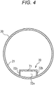
4 ]4 ist eine schematische Querschnittsansicht entlang einer Linie X-X von3 .[4th ]4th FIG. 13 is a schematic cross sectional view taken along line XX of FIG3 . -
[
5 ]5 ist ein schematisches Konfigurationsdiagramm eines Fahrzeugs, auf das ein Blowby-Gas-System gemäß einer dritten Ausführungsform angewendet wird.[5 ]5 FIG. 12 is a schematic configuration diagram of a vehicle to which a blow-by gas system according to a third embodiment is applied.
BESCHREIBUNG VON AUSFÜHRUNGSFORMENDESCRIPTION OF EMBODIMENTS
[Erste Ausführungsform][First embodiment]
Hierin nachfolgend ist ein Blowby-Gas-System
Der Verbrennungsmotor
Ein bestimmter Typ des Verbrennungsmotors
Der Einlasskanal
Der Auflader
Das Luftverdichtungssystem
Der Luftverdichter
Eine Antriebsquelle des Luftverdichters
Der Lufteinführungskanal
Der Auslassluftkanal
Der Lufttrockner
Der Luftbehälter
Als Beispiel verwendet hier das Luftverdichtungssystem
Das Blowby-Gas-System
Der Blowby-Gas-Strömungsweg
Der Ölabscheider
Das enthaltene Öl in dem Blowby-Gas, das aus dem Verbrennungsmotor
Als nächstes wird der „vorbestimmte Abschnitt“ als ein Verbindungsziel des stromabwärtigen Endabschnitts des Blowby-Gas-Strömungswegs
Das heißt in dem Blowby-Gas-Strömungsweg
Bei dieser Konfiguration wird ein Teil des Blowby-Gases, das durch den Blowby-Gas-Strömungsweg
Betriebliche Auswirkungen der oben beschriebenen gegenwärtigen Ausführungsform werden wie folgt zusammengefasst. Erstens kann gemäß der vorliegenden Ausführungsform ein Teil des Blowby-Gases, das durch den Blowby-Gas-Strömungsweg
Da der Lufttrockner
(Zweite Ausführungsform)(Second embodiment)
Als nächstes ist ein Blowby-Gas-System
Ein „vorbestimmter Abschnitt“ als ein Verbindungsziel eines stromabwärtigen Endabschnitts des Blowby-Gas-Strömungswegs
Spezifischer ist der stromabwärtige Endabschnitt des Blowby-Gas-Strömungswegs
Wie es in
Spezifisch beinhaltet das Führungselement
Innerhalb des Einlasskanals
Gemäß dem Blowby-Gas-System
(Modifizierung der zweiten Ausführungsform)(Modification of the second embodiment)
Obwohl das Blowby-Gas-System
(Dritte Ausführungsform)(Third embodiment)
Als nächstes ist ein Blowby-Gas-System
Ein Verbindungsziel eines stromabwärtigen Endabschnitts des Blowby-Gas-Strömungswegs
Gemäß der vorliegenden, oben beschriebenen Ausführungsform wird das Blowby-Gas, nachdem es durch den Ölabscheider
Obwohl die Ausführungsformen der vorliegenden Erfindung oben beschrieben wurden, ist die vorliegende Erfindung nicht auf solche spezifischen Ausführungsformen beschränkt, und es können verschiedene Modifikationen und Änderungen im Rahmen des in den Ansprüchen beschriebenen Kerns der vorliegenden Erfindung vorgenommen werden.Although the embodiments of the present invention have been described above, the present invention is not limited to such specific embodiments, and various modifications and changes can be made within the gist of the present invention described in the claims.
Diese Anmeldung basiert auf der am 4. Juni 2018 eingereichten japanischen Patentanmeldung Nr.
GEWERBLICHE ANWENDBARKEITCOMMERCIAL APPLICABILITY
Gemäß dem Blowby-Gas-System der vorliegenden Offenbarung ist es möglich, eine durch eine Ölverkokungssubstanz verursachte Verringerung der Aufladeeffizienz eines Aufladers zu verhindern.According to the blow-by gas system of the present disclosure, it is possible to prevent a reduction in the charging efficiency of a supercharger caused by an oil coking substance.
BezugszeichenlisteList of reference symbols
- 1, 1a, 1b1, 1a, 1b
- Fahrzeugvehicle
- 1010
- VerbrennungsmotorInternal combustion engine
- 2020th
- EinlasskanalInlet port
- 3030th
- LuftfilterAir filter
- 4040
- AufladerCharger
- 4141
- Verdichtercompressor
- 5050
- LuftverdichtungssystemAir compression system
- 5151
- Luftverdichter (Luftansaugmechanismus)Air compressor (air intake mechanism)
- 5252
- EinführungsöffnungInsertion opening
- 5353
- AuslassöffnungOutlet opening
- 5454
- LufttrocknerAir dryer
- 5555
- LuftbehälterAir tank
- 5656
- LufteinführungskanalAir inlet duct
- 5757
- AuslassluftkanalExhaust air duct
- 60, 60a, 60b60, 60a, 60b
- Blowby-Gas-SystemBlowby gas system
- 61, 61a, 61b61, 61a, 61b
- Blowby-Gas-StrömungswegBlowby gas flow path
- 6262
- ÖlabscheiderOil separator
- 7070
- FührungselementGuide element
ZITATE ENTHALTEN IN DER BESCHREIBUNGQUOTES INCLUDED IN THE DESCRIPTION
Diese Liste der vom Anmelder aufgeführten Dokumente wurde automatisiert erzeugt und ist ausschließlich zur besseren Information des Lesers aufgenommen. Die Liste ist nicht Bestandteil der deutschen Patent- bzw. Gebrauchsmusteranmeldung. Das DPMA übernimmt keinerlei Haftung für etwaige Fehler oder Auslassungen.This list of the documents listed by the applicant was generated automatically and is included solely for the better information of the reader. The list is not part of the German patent or utility model application. The DPMA assumes no liability for any errors or omissions.
Zitierte PatentliteraturPatent literature cited
- JP 2017020454 A [0003]JP 2017020454 A [0003]
- JP 2018107087 [0044]JP 2018107087 [0044]
Claims (4)
Applications Claiming Priority (3)
| Application Number | Priority Date | Filing Date | Title |
|---|---|---|---|
| JP2018-107087 | 2018-06-04 | ||
| JP2018107087A JP2019210855A (en) | 2018-06-04 | 2018-06-04 | Blowby gas system |
| PCT/JP2019/021971 WO2019235419A1 (en) | 2018-06-04 | 2019-06-03 | Blow-by gas system |
Publications (2)
| Publication Number | Publication Date |
|---|---|
| DE112019002823T5 true DE112019002823T5 (en) | 2021-02-18 |
| DE112019002823B4 DE112019002823B4 (en) | 2024-05-02 |
Family
ID=68770333
Family Applications (1)
| Application Number | Title | Priority Date | Filing Date |
|---|---|---|---|
| DE112019002823.5T Active DE112019002823B4 (en) | 2018-06-04 | 2019-06-03 | Blowby gas system |
Country Status (5)
| Country | Link |
|---|---|
| US (1) | US11203955B2 (en) |
| JP (1) | JP2019210855A (en) |
| CN (1) | CN112236581A (en) |
| DE (1) | DE112019002823B4 (en) |
| WO (1) | WO2019235419A1 (en) |
Families Citing this family (5)
| Publication number | Priority date | Publication date | Assignee | Title |
|---|---|---|---|---|
| JP7230853B2 (en) * | 2020-02-28 | 2023-03-01 | いすゞ自動車株式会社 | Diagnostic device and diagnostic method |
| CN114738078B (en) * | 2022-05-09 | 2023-06-09 | 一汽解放汽车有限公司 | An engine blow-by gas dehydration device, a blow-by gas dewatering method, and a vehicle |
| US11976616B2 (en) * | 2022-09-12 | 2024-05-07 | Estis Compression, LLC | Compression emissions evacuator |
| US12129816B2 (en) | 2022-09-12 | 2024-10-29 | Estis Compression, LLC | Compression emissions evacuator |
| CN115585033B (en) * | 2022-11-22 | 2023-05-16 | 苏州英特模科技股份有限公司 | Crankcase dilution system and test system of hydrogen internal combustion engine |
Family Cites Families (10)
| Publication number | Priority date | Publication date | Assignee | Title |
|---|---|---|---|---|
| US8235029B2 (en) * | 2005-03-09 | 2012-08-07 | Rem Technology Inc. | Method and apparatus for processing diluted fugitive gases |
| JP2006316698A (en) * | 2005-05-12 | 2006-11-24 | Toyota Motor Corp | Oil mist processing equipment |
| JP5812892B2 (en) * | 2012-02-17 | 2015-11-17 | 愛三工業株式会社 | Ejecta |
| DE202013008611U1 (en) | 2013-09-26 | 2014-09-29 | Reinz-Dichtungs-Gmbh | Ventilation system for supercharged internal combustion engines |
| CN204041160U (en) * | 2014-07-29 | 2014-12-24 | 长城汽车股份有限公司 | For the recovering device of crankcase gas blowby, system and vehicle |
| US10843112B2 (en) | 2014-08-29 | 2020-11-24 | Nabtesco Automotive Corporation | Oil separator and compressed air drying system |
| JP6332177B2 (en) | 2015-07-14 | 2018-05-30 | トヨタ自動車株式会社 | Blowby gas recirculation device for internal combustion engine |
| JP2017031898A (en) * | 2015-08-03 | 2017-02-09 | トヨタ自動車株式会社 | Blow-by gas recirculation device for internal combustion engine |
| JP6238382B2 (en) * | 2016-07-13 | 2017-11-29 | ナブテスコオートモーティブ株式会社 | Oil separator |
| JP2018107087A (en) | 2016-12-28 | 2018-07-05 | 三菱自動車工業株式会社 | Battery pack cooling system |
-
2018
- 2018-06-04 JP JP2018107087A patent/JP2019210855A/en active Pending
-
2019
- 2019-06-03 US US16/972,529 patent/US11203955B2/en active Active
- 2019-06-03 WO PCT/JP2019/021971 patent/WO2019235419A1/en not_active Ceased
- 2019-06-03 DE DE112019002823.5T patent/DE112019002823B4/en active Active
- 2019-06-03 CN CN201980037954.0A patent/CN112236581A/en not_active Withdrawn
Also Published As
| Publication number | Publication date |
|---|---|
| CN112236581A (en) | 2021-01-15 |
| WO2019235419A1 (en) | 2019-12-12 |
| JP2019210855A (en) | 2019-12-12 |
| US11203955B2 (en) | 2021-12-21 |
| US20210270157A1 (en) | 2021-09-02 |
| DE112019002823B4 (en) | 2024-05-02 |
Similar Documents
| Publication | Publication Date | Title |
|---|---|---|
| DE112019002823B4 (en) | Blowby gas system | |
| DE69805353T2 (en) | Crankcase ventilation system | |
| EP1065350B1 (en) | Combustion engine with a breather device | |
| DE102014013714B4 (en) | Internal combustion engine, especially for a motor vehicle | |
| CH664798A5 (en) | DEVICE FOR RETURNING THE BLOW-OFF QUANTITY FROM THE CRANKCASE. | |
| DE102013106879A1 (en) | Jet engine with at least one oil separator | |
| DE102012001458A1 (en) | Lifting cylinder internal combustion engine for passenger car, has blocking device controlled depending on pressure in fresh gas strand behind compressor, and oil separator integrated in deventilation line | |
| WO2006050812A1 (en) | Breather device for the crankcase of a forced induction internal combustion engine | |
| DE102010004805A1 (en) | Cylindrical head cover for recharged internal combustion engine of motor vehicle, has cylindrical head cover housing, cylindrical head cover internal space, oil-separating device, two return valves and anti-vacuum valve | |
| EP2549093B1 (en) | Combustion engine | |
| DE102009041223A1 (en) | Exhaust gas turbocharger arrangement, thus equipped drive system and method for laying out the drive system | |
| DE102010012118A1 (en) | Internal combustion engine for motor vehicle, has deposition device separating mixture of lubricant from lubricant and gas, where mixture of lubricant and gas bypasses deposition device by bypass device | |
| DE102014222494A1 (en) | BLOWBY GAS TREATMENT DEVICE FOR A COMBUSTION ENGINE | |
| DE102019101141A1 (en) | Ventilation device for a crankcase | |
| DE102016015111A1 (en) | Internal combustion engine | |
| EP4698760A1 (en) | Internal combustion engine for a motor vehicle, and motor vehicle | |
| EP3523514B1 (en) | Device for the ventilation of a crankcase of an internal combustion engine | |
| DE202007013327U1 (en) | Device for separating oil from an air stream | |
| DE102011075933A1 (en) | Internal combustion engine | |
| DE102018008766A1 (en) | Internal combustion engine for a motor vehicle, in particular for a motor vehicle | |
| DE102014019144A1 (en) | Crankcase breather for an internal combustion engine, in particular a motor vehicle | |
| DE102018000836A1 (en) | Motor vehicle with a ventilation system for oil vapors and fuel vapors | |
| DE19646637A1 (en) | Breather valve arrangement for crankcase of internal combustion engine of vehicle | |
| DE102020005110A1 (en) | Exhaust gas recirculation device for an internal combustion engine, in particular for a motor vehicle | |
| DE102010009913A1 (en) | Internal combustion engine |
Legal Events
| Date | Code | Title | Description |
|---|---|---|---|
| R012 | Request for examination validly filed | ||
| R016 | Response to examination communication | ||
| R018 | Grant decision by examination section/examining division | ||
| R082 | Change of representative |
Representative=s name: MEISSNER BOLTE PATENTANWAELTE RECHTSANWAELTE P, DE |
|
| R020 | Patent grant now final |