Hintergrund der ErfindungBackground of the invention
Die vorliegende Offenbarung betrifft ein Koordinatenmessgerät. Ein Satz von Koordinatenmessgeräten gehört zu einer Klasse von Instrumenten, die die dreidimensionalen (3D) Koordinaten eines Punkts durch Senden eines Laserstrahls zu dem Punkt messen. Der Laserstrahl kann direkt auf den Punkt oder auf ein Retroreflektorziel, das sich in Kontakt mit dem Punkt befindet, auftreffen. In jedem der beiden Fälle ermittelt das Instrument die Koordinaten des Punkts, indem es den Abstand und die zwei Winkel zu dem Ziel misst. Der Abstand wird mit einem Distanzmessgerät wie beispielsweise einem Absolutdistanzmesser oder einem Interferometer gemessen. Die Winkel werden mit einem Winkelmessgerät wie beispielsweise einem Winkelkodierer gemessen. Ein kardanisch aufgehängter Strahllenkungsmechanismus in dem Instrument lenkt den Laserstrahl zu dem betreffenden Punkt.The present disclosure relates to a coordinate measuring machine. A set of coordinate measuring machines belongs to a class of instruments that measure the three-dimensional (3D) coordinates of a point by sending a laser beam to the point. The laser beam can impinge directly on the spot or on a retroreflector target that is in contact with the spot. In either case, the instrument determines the coordinates of the point by measuring the distance and the two angles to the target. The distance is measured with a distance measuring device such as an absolute distance meter or an interferometer. The angles are measured with an angle encoder such as an angle encoder. A gimbaled beam steering mechanism in the instrument directs the laser beam to the point in question.
Der Lasertracker ist ein besonderer Typ eines Koordinatenmessgeräts, das das Retroreflektorziel mit einem oder mehreren Laserstrahlen verfolgt, den bzw. die es emittiert. Koordinatenmessgeräte, die nahe mit dem Lasertracker verwandt sind, sind der Laserscanner und die Totalstation. Der Laserscanner sendet schrittweise einen oder mehrere Laserstrahlen zu Punkten auf einer Oberfläche. Er nimmt das von der Oberfläche gestreute Licht auf und ermittelt aus diesem Licht den Abstand und zwei Winkel zu jedem Punkt. Die Totalstation, die am häufigsten bei Vermessungsanwendungen eingesetzt wird, kann zum Messen der Koordinaten von diffus streuenden bzw. retroreflektierenden Zielen verwendet werden. Der Begriff „Lasertracker” wird nachstehend in weitem Sinn so benutzt, dass er Laserscanner und Totalstationen umfasst.The laser tracker is a particular type of coordinate measuring machine that tracks the retroreflector target with one or more laser beams it emits. Coordinate measuring machines, which are closely related to the laser tracker, are the laser scanner and the total station. The laser scanner gradually sends one or more laser beams to points on a surface. He picks up the light scattered from the surface and uses this light to determine the distance and two angles to each point. The total station, most commonly used in surveying applications, can be used to measure the coordinates of diffuse-scattering or retroreflective targets. The term "laser tracker" is used broadly to encompass laser scanners and total stations.
Normalerweise sendet der Lasertracker einen Laserstrahl zu einem Retroreflektorziel. Ein üblicher Typ eines Retroreflektorziels ist der sphärisch montierte Retroreflektor (SMR; spherically mounted retroreflector), der einen in eine Metallkugel eingebetteten Würfelecken-Retroreflektor umfasst. Der Würfelecken-Retroreflektor umfasst drei zueinander senkrechte Spiegel. Der Scheitelpunkt, der der gemeinsame Schnittpunkt der drei Spiegel ist, befindet sich in der Mitte der Kugel. Wegen dieser Anordnung der Würfelecke in der Kugel bleibt der senkrechte Abstand vom Scheitelpunkt zu einer beliebigen Oberfläche, auf welcher der SMR aufliegt, sogar konstant, während der SMR gedreht wird. Demzufolge kann der Lasertracker die 3D-Koordinaten einer Oberfläche messen, indem er der Position eines SMR folgt, während dieser über die Oberfläche bewegt wird. Anders ausgedrückt bedeutet dies, dass der Lasertracker lediglich drei Freiheitsgrade (einen Radialabstand und zwei Winkel) messen muss, um die 3D-Koordinaten einer Oberfläche vollständig zu charakterisieren.Normally, the laser tracker sends a laser beam to a retroreflector target. One common type of retroreflector target is the spherically mounted retroreflector (SMR), which includes a cube-corner retroreflector embedded in a metal sphere. The cube-corner retroreflector comprises three mutually perpendicular mirrors. The vertex, which is the common intersection of the three mirrors, is in the center of the sphere. Because of this arrangement of the cube corner in the sphere, the perpendicular distance from the vertex to any surface on which the SMR rests remains even constant as the SMR is rotated. As a result, the laser tracker can measure the 3D coordinates of a surface by following the position of an SMR as it moves across the surface. In other words, this means that the laser tracker only has to measure three degrees of freedom (a radial distance and two angles) in order to fully characterize the 3D coordinates of a surface.
Ein Lasertrackertyp enthält nur ein Interferometer (IFM) ohne einen Absolutdistanzmesser (ADM). Falls ein Objekt den Weg des von einem dieser Tracker ausgehenden Laserstrahls blockiert, verliert das IFM seinen Abstandsbezug. Der Bediener muss dann den Retroreflektor zu einer bekannten Stelle nachführen, um die Rückstellung auf einen Referenzabstand durchzuführen, bevor die Messung fortgesetzt wird. Eine Methode zur Umgehung dieser Einschränkung besteht darin, einen ADM in den Tracker einzubringen. Der ADM kann den Abstand in einer Anvisieren-und-Auslösen-Weise messen, die unten ausführlicher beschrieben wird. Einige Lasertracker enthalten nur einen ADM ohne ein Interferometer. Das an Bridges et al. erteilte US-Patent US 7,352,446 B2 ('446), dessen Inhalt hierin durch Verweis einbezogen wird, beschreibt einen Lasertracker, der nur einen ADM (und kein IFM) aufweist, der zur genauen Abtastung eines sich bewegenden Ziels in der Lage ist. Vor dem Patent '446 waren Absolutdistanzmesser für das genaue Auffinden der Position eines sich bewegenden Ziels zu langsam.A laser tracker type contains only one interferometer (IFM) without an absolute distance meter (ADM). If an object blocks the path of the laser beam emanating from one of these trackers, the IFM loses its distance reference. The operator must then track the retroreflector to a known location to reset to a reference distance before continuing the measurement. One way around this limitation is to put an ADM in the tracker. The ADM can measure the distance in a sight-and-trigger manner, which is described in more detail below. Some laser trackers only contain an ADM without an interferometer. The Bridges et al. issued US patent US 7,352,446 B2 ('446), the contents of which are incorporated herein by reference, describes a laser tracker having only one ADM (and no IFM) capable of accurately tracking a moving target. Prior to the '446 patent, absolute distance meters were too slow to accurately locate the position of a moving target.
Ein Kardanmechanismus in dem Lasertracker kann verwendet werden, um einen Laserstrahl von dem Tracker auf den SMR zu richten. Ein Teil des von dem SMR retroreflektierten Lichts tritt in den Lasertracker ein und geht anschließend auf einen Positionsdetektor durch. Ein Steuersystem im Lasertracker kann die Position des Lichts auf dem Positionsdetektor nutzen, um die Drehwinkel der mechanischen Achsen des Lasertrackers derart einzustellen, dass der Laserstrahl auf den SMR zentriert bleibt. Auf diese Weise ist der Tracker in der Lage, einem SMR zu folgen (nachgeführt zu werden), der über die Oberfläche eines betreffenden Objekts bewegt wird. Der für einen Lasertracker verwendete Kardanmechanismus kann für verschiedene andere Anwendungen eingesetzt werden. Als einfaches Beispiel kann der Lasertracker in einem kardanisch aufgehängten Lenkungsmechanismus benutzt werden, der einen sichtbaren Zeigerstrahl, aber keinen Distanzmesser für die Lenkung eines Lichtstrahls zu einer Reihe von Retroreflektorzielen und für die Messung der Winkel von jedem der Ziele aufweist.A gimbal mechanism in the laser tracker can be used to direct a laser beam from the tracker to the SMR. A portion of the retroreflected light from the SMR enters the laser tracker and then passes to a position detector. A control system in the laser tracker can use the position of the light on the position detector to adjust the rotational angles of the laser track's mechanical axes so that the laser beam remains centered on the SMR. In this way, the tracker is able to follow (track) an SMR that is being moved across the surface of a subject object. The gimbal mechanism used for a laser tracker can be used for various other applications. As a simple example, the laser tracker may be used in a gimballed steering mechanism that has a visible pointer beam but no distance meter for directing a light beam to a series of retroreflector targets and for measuring the angles of each of the targets.
Winkelmessgeräte wie beispielsweise Winkelkodierer werden an den mechanischen Achsen des Trackers befestigt. Die eine Abstandsmessung und die zwei Winkelmessungen, die der Lasertracker durchführt, reichen aus, um die dreidimensionale Position des SMR vollständig anzugeben.Angle encoders such as angle encoders are attached to the tracker's mechanical axes. The one distance measurement and the two angle measurements made by the laser tracker are sufficient to fully state the three-dimensional position of the SMR.
Mehrere Lasertracker sind verfügbar oder wurden für die Messung von sechs Freiheitsgraden statt der üblichen drei Freiheitsgrade vorgeschlagen. Beispielhafte Systeme mit sechs Freiheitsgraden (6-DOF-Systeme; im Engl. „six degrees of freedom”) werden in dem an Bridges et al. erteilten US-Patent US 7,800,758 B1 ('758), dessen Inhalt hierin durch Verweis einbezogen wird, und der veröffentlichten US-amerikanischen Patentanmeldung US 2010/0128259 A1 von Bridges et al., deren Inhalt hierin durch Verweis einbezogen wird, beschrieben.Several laser trackers are available or have been designed to measure six degrees of freedom instead of the usual three degrees of freedom proposed. Exemplary six-degree-of-freedom (6-DOF) systems are described in the Bridges et al. issued US patent US Pat. No. 7,800,758 B1 ('758), the contents of which are incorporated herein by reference, and US Published Patent Application US 2010/0128259 A1 to Bridges et al., The contents of which are incorporated herein by reference.
In der Vergangenheit waren 6-DOF-Sonden und SMRs separate Zusatzteile, die relativ teuer waren. Es besteht Bedarf an einem Zusatzteil, das relativ preiswert ist und in dem die Funktionalität eines SMR und einer 6-DOF-Sonde kombiniert ist.In the past, 6-DOF probes and SMRs were separate accessories that were relatively expensive. There is a need for an accessory which is relatively inexpensive and which combines the functionality of an SMR and a 6-DOF probe.
Zusammenfassung der ErfindungSummary of the invention
Ein Verfahren zur Messung dreidimensionaler Koordinaten eines Sondenmittelpunkts umfasst folgende Schritte: Bereitstellen eines sphärisch montierten Retroreflektors, wobei der sphärisch montierte Retroreflektor einen in einem Retroreflektorkörper montierten Retroreflektor umfasst, wobei der Retroreflektorkörper eine erste Kugelform über einen ersten Abschnitt seiner Außenfläche aufweist, wobei der erste Abschnitt einen Zielmittelpunkt aufweist, wobei der Retroreflektor dafür konfiguriert ist, einen ersten Lichtstrahl zu empfangen und einen zweiten Lichtstrahl zurückzuwerfen, wobei der zweite Lichtstrahl ein Teil des ersten Lichtstrahls ist, wobei sich der zweite Lichtstrahl in einer Richtung bewegt, die der Richtung des ersten Lichtstrahls im Wesentlichen entgegengesetzt ist. Das Verfahren umfasst auch: Bereitstellen einer Sondenbaugruppe, wobei die Sondenbaugruppe einen Sondenstift und einen Sondenkopf umfasst, wobei der Sondenstift die Sondenspitze umfasst, wobei die Sondenspitze eine zweite Kugelform über einen zweiten Abschnitt ihrer Oberfläche aufweist, wobei der zweite Abschnitt einen Sondenmittelpunkt aufweist, wobei der Sondenkopf dafür konfiguriert ist, den sphärisch montierten Retroreflektor aufzunehmen und eine Drehung des sphärisch montierten Retroreflektors um den Zielmittelpunkt zu gestatten, während der Zielmittelpunkt an einer im Wesentlichen gleich bleibenden Position relativ zu der Sondenbaugruppe gehalten wird. Das Verfahren umfasst ferner: Bereitstellen eines Koordinatenmessgeräts, wobei das Koordinatenmessgerät einen ersten Motor, einen zweiten Motor, ein erstes Winkelmessgerät, ein zweites Winkelmessgerät, einen Distanzmesser, einen Positionsdetektor, ein Steuersystem, einen Orientierungssensor und einen Prozessor umfasst, wobei der erste Motor und der zweite Motor zusammen dafür konfiguriert sind, den ersten Lichtstrahl in eine erste Richtung zu richten, wobei die erste Richtung durch einen ersten Drehwinkel um eine erste Achse und einen zweiten Drehwinkel um eine zweite Achse bestimmt wird, wobei der erste Drehwinkel durch den ersten Motor erzeugt wird und der zweite Drehwinkel durch den zweiten Motor erzeugt wird, wobei das erste Winkelmessgerät für das Messen des ersten Drehwinkels konfiguriert ist und das zweite Winkelmessgerät für das Messen des zweiten Drehwinkels konfiguriert ist, wobei der Distanzmesser dafür konfiguriert ist, einen ersten Abstand von dem Koordinatenmessgerät zu dem sphärisch montierten Retroreflektor basierend zumindest teilweise auf einem dritten Teil des von einem ersten optischen Detektor empfangenen zweiten Lichtstrahls zu messen, wobei der Positionsdetektor dafür konfiguriert ist, ein erstes Signal als Reaktion auf eine Position eines vierten Teils des zweiten Lichtstrahls auf dem Positionsdetektor zu erzeugen, wobei das Steuersystem dafür konfiguriert ist, dem ersten Motor ein zweites Signal zu senden und dem zweiten Motor ein drittes Signal zu senden, wobei das zweite Signal und das dritte Signal zumindest teilweise auf dem ersten Signal basieren, wobei das Steuersystem dafür konfiguriert ist, die erste Richtung des ersten Lichtstrahls auf die räumliche Position des sphärisch montierten Retroreflektors einzustellen, wobei der Orientierungssensor dafür konfiguriert ist, drei Orientierungsfreiheitsgrade der Sondenbaugruppe zu messen, wobei der Prozessor dafür konfiguriert ist, dreidimensionale Koordinaten des Sondenmittelpunkts zu ermitteln, wobei die dreidimensionalen Koordinaten zumindest teilweise auf dem ersten Abstand, dem ersten Drehwinkel, dem zweiten Drehwinkel und den drei Orientierungsfreiheitsgraden basieren. Das Verfahren umfasst des Weiteren: Anordnen des sphärisch montierten Retroreflektors auf dem Sondenkopf; Bewegen des Sondenmittelpunkts zu dem ersten Punkt; Richten des ersten Lichtstrahls von dem Koordinatenmessgerät auf den sphärisch montierten Retroreflektor; Messen des ersten Abstands; Messen des ersten Drehwinkels; Messen des zweiten Drehwinkels; Messen der drei Orientierungsfreiheitsgrade basierend zumindest teilweise auf einer durch den Orientierungssensor bereitgestellten Information; Ermitteln eines ersten Satzes dreidimensionaler Koordinaten des Sondenmittelpunkts basierend zumindest teilweise auf dem ersten Abstand, dem ersten Drehwinkel, dem zweiten Drehwinkel und den drei Orientierungsfreiheitsgraden; Speichern des ersten Satzes dreidimensionaler Koordinaten des Sondenmittelpunkts; Entfernen des sphärisch montierten Retroreflektors aus dem Sondenkopf; Bewegen des Zielmittelpunkts zu dem zweiten Punkt nach Entfernen des sphärisch montierten Retroreflektors aus dem Sondenkopf; Richten des ersten Lichtstrahls von dem Koordinatenmessgerät auf den sphärisch montierten Retroreflektor mit dem Zielmittelpunkt im zweiten Punkt; Messen eines zweiten Abstands mit dem Zielmittelpunkt im zweiten Punkt; Messen eines dritten Drehwinkels mit dem Zielmittelpunkt im zweiten Punkt; Messen eines vierten Drehwinkels mit dem Zielmittelpunkt im zweiten Punkt; Ermitteln eines zweiten Satzes dreidimensionaler Koordinaten des Zielmittelpunkts basierend zumindest teilweise auf dem zweiten Abstand, dem dritten Drehwinkel und dem vierten Drehwinkel; und Speichern des zweiten Satzes dreidimensionaler Koordinaten des Zielmittelpunkts.A method for measuring three-dimensional coordinates of a probe center comprises the steps of: providing a spherically mounted retroreflector, wherein the spherically mounted retroreflector comprises a retroreflector mounted in a retroreflector body, the retroreflector body having a first spherical shape over a first portion of its outer surface, the first portion including a Target center, wherein the retroreflector is configured to receive a first light beam and to reflect a second light beam, wherein the second light beam is a part of the first light beam, wherein the second light beam moves in a direction substantially the direction of the first light beam is opposite. The method also includes: providing a probe assembly, the probe assembly comprising a probe pin and a probe head, the probe pin comprising the probe tip, the probe tip having a second spherical shape over a second portion of its surface, the second portion having a probe center; Probe head is configured to receive the spherical mounted retroreflector and to allow rotation of the spherically mounted retroreflector around the target center, while the target center is held at a substantially constant position relative to the probe assembly. The method further comprises: providing a coordinate measuring machine, the coordinate measuring machine comprising a first motor, a second motor, a first angle measuring device, a second angle measuring device, a distance meter, a position detector, a control system, an orientation sensor and a processor, wherein the first motor and the second motors are configured together to direct the first light beam in a first direction, wherein the first direction is determined by a first angle of rotation about a first axis and a second angle of rotation about a second axis, wherein the first angle of rotation is generated by the first motor and the second angle of rotation is generated by the second motor, wherein the first angle meter is configured to measure the first angle of rotation and the second angle meter is configured to measure the second angle of rotation, the distance meter configured to be a first distance from the coordinate measurement apparatus to measure the spherically mounted retroreflector based at least in part on a third portion of the second light beam received from a first optical detector, the position detector being configured to deliver a first signal in response to a position of a fourth portion of the second light beam on the position detector wherein the control system is configured to send a second signal to the first motor and to send a third signal to the second motor, wherein the second signal and the third signal are based at least in part on the first signal, the control system being configured to adjusting the first direction of the first light beam to the spatial position of the spherically mounted retroreflector, wherein the orientation sensor is configured to measure three degrees of freedom of orientation of the probe assembly, the processor configured to receive three-dimensional coordinates of the probe center The three-dimensional coordinates are based at least in part on the first distance, the first rotation angle, the second rotation angle, and the three orientation degrees of freedom. The method further comprises: placing the spherically mounted retroreflector on the probe head; Moving the probe center to the first point; Directing the first beam of light from the coordinate measuring machine onto the spherically mounted retroreflector; Measuring the first distance; Measuring the first angle of rotation; Measuring the second angle of rotation; Measuring the three orientation degrees of freedom based at least in part on information provided by the orientation sensor; Determining a first set of three-dimensional coordinates of the probe center based at least in part on the first distance, the first rotation angle, the second rotation angle, and the three orientation degrees of freedom; Storing the first set of three-dimensional coordinates of the probe center; Removing the spherically mounted retroreflector from the probe head; Moving the target center to the second point after removing the spherically mounted retroreflector from the probe head; Directing the first light beam from the coordinate measuring machine onto the spherically mounted retroreflector with the target center at the second point; Measuring a second distance with the target center in the second point; Measuring a third angle of rotation with the target center in the second point; Measuring a fourth angle of rotation with the target center in the second point; Determining a second set of three-dimensional coordinates of the target center based at least partially on the second distance, the third rotation angle and the fourth rotation angle; and storing the second set of three-dimensional coordinates of the destination midpoint.
Kurze Beschreibung der ZeichnungenBrief description of the drawings
Es wird nun auf die Zeichnungen Bezug genommen, wobei beispielhafte Ausgestaltungen dargestellt sind, die nicht als den gesamten Schutzbereich der Offenbarung einschränkend aufzufassen sind und wobei die Elemente in mehreren Figuren gleich nummeriert sind. Es zeigen:Referring now to the drawings, exemplary embodiments are shown that are not to be construed as limiting the entire scope of the disclosure, and wherein the elements in several figures are numbered alike. Show it:
1: eine perspektivische Darstellung eines Lasertrackersystems mit einem Retroreflektorziel gemäß einer Ausgestaltung der vorliegenden Erfindung; 1 : A perspective view of a laser tracker system with a retroreflector target according to one embodiment of the present invention;
2: eine perspektivische Darstellung eines Lasertrackersystems mit einem 6-DOF-Ziel gemäß einer Ausgestaltung der vorliegenden Erfindung; 2 FIG. 3 is a perspective view of a laser tracker system having a 6-DOF target according to an embodiment of the present invention; FIG.
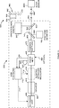
3: ein Blockdiagramm, das die Elemente der Optik und Elektronik des Lasertrackers gemäß einer Ausgestaltung der vorliegenden Erfindung beschreibt; 3 3 is a block diagram describing the elements of the optics and electronics of the laser tracker according to an embodiment of the present invention;
4: die 4A und 4B umfasst, zwei Typen von afokalen Strahlaufweitern des Stands der Technik; 4 : the 4A and 4B includes two types of afocal beam expander of the prior art;
5: eine faseroptische Strahleinkopplung des Stands der Technik; 5 : a prior art fiber optic beam coupler;
6A–D: schematische Figuren, die vier Typen von Positionsdetektorbaugruppen des Stands der Technik darstellen; 6A D: schematic figures illustrating four types of position detector assemblies of the prior art;
6E und 6F: schematische Figuren, die Positionsdetektorbaugruppen gemäß Ausgestaltungen der vorliegenden Erfindung darstellen; 6E and 6F Fig. 12: schematic figures illustrating position detector assemblies according to embodiments of the present invention;
7: ein Blockdiagramm von elektrischen und elektrooptischen Elementen in einem ADM des Stands der Technik; 7 FIG. 3 is a block diagram of electrical and electro-optical elements in a prior art ADM; FIG.
8A und 8B: schematische Figuren, die faseroptische Elemente in einem Glasfasernetz des Stands der Technik darstellen; 8A and 8B Fig. 12: schematic figures illustrating fiber optic elements in a prior art glass fiber network;
8C: eine schematische Figur, die faseroptische Elemente in einem Glasfasernetz gemäß einer Ausgestaltung der vorliegenden Erfindung darstellt; 8C Fig. 1 is a schematic figure illustrating fiber optic elements in a fiber optic network according to an embodiment of the present invention;
9: eine Explosionsdarstellung eines Lasertrackers des Stands der Technik; 9 : An exploded view of a laser tracker of the prior art;
10: eine Querschnittsdarstellung eines Lasertrackers des Stands der Technik; 10 : A cross-sectional view of a laser tracker of the prior art;
11: ein Blockdiagramm der Berechnungs- und Kommunikationselemente eines Lasertrackers gemäß einer Ausgestaltung der vorliegenden Erfindung. 11 : A block diagram of the computing and communication elements of a laser tracker according to an embodiment of the present invention.
12A: ein Blockdiagramm von Elementen in einem Lasertracker, bei dem eine einzige Wellenlänge verwendet wird, gemäß einer Ausgestaltung der vorliegenden Erfindung; 12A FIG. 3 is a block diagram of elements in a laser tracker using a single wavelength, according to an embodiment of the present invention; FIG.
12B: ein Blockdiagramm von Elementen in einem Lasertracker, bei dem eine einzige Wellenlänge verwendet wird, gemäß einer Ausgestaltung der vorliegenden Erfindung; 12B FIG. 3 is a block diagram of elements in a laser tracker using a single wavelength, according to an embodiment of the present invention; FIG.
13: ein Blockdiagramm von Elementen in einem Lasertracker mit 6-DOF-Kapazität gemäß einer Ausgestaltung der vorliegenden Erfindung; 13 10 is a block diagram of elements in a 6 DOF capacitance laser tracker according to an embodiment of the present invention;
14A und 14B: Vorderansichten eines magnetisch an einem 6-DOF-Sondensockel befestigten 6-DOF-SMR bzw. eines auf einen 6-DOF-Sondensockel geklemmten 6-DOF-SMR gemäß einer Ausgestaltung der vorliegenden Erfindung; 14A and 14B FIG. 3: Front views of a 6-DOF SMR magnetically attached to a 6-DOF probe socket, or a 6-DOF SMR clamped to a 6-DOF probe socket, in accordance with an embodiment of the present invention; FIG.
15A: eine Vorderansicht einer Sondenbaugruppe und eines auf einer Kompensationshalterung angeordneten 6-DOF-SMR und 15B eine Querschnittsdarstellung der Kompensationshalterung gemäß einer Ausgestaltung der vorliegenden Erfindung; 15A FIG. 4 is a front view of a probe assembly and a 6-DOF SMR mounted on a compensation mount. FIG 15B a cross-sectional view of the compensation holder according to an embodiment of the present invention;
16A–C: Vorderansichten, die die Gier-, Nick- und Rollbewegungen der 6-DOF-Sonde zum Erhalten von Kompensationsparametern gemäß einer Ausgestaltung der vorliegenden Erfindung angeben; 16A C: front views indicating the yaw, pitch and roll movements of the 6-DOF probe for obtaining compensation parameters according to an embodiment of the present invention;
17: eine Vorderansicht einer Sondenbaugruppe und eines 6-DOF-SMR, wobei die Sondenbaugruppe und der SMR Rast- und Passmerkmale gemäß einer Ausgestaltung der vorliegenden Erfindung aufweisen; 17 3 is a front view of a probe assembly and a 6-DOF SMR, wherein the probe assembly and the SMR have latch and mating features according to an embodiment of the present invention;
18: ein Ablaufdiagramm eines Verfahrens zur Messung dreidimensionaler Koordinaten gemäß einer Ausgestaltung der vorliegenden Erfindung; 18 3 is a flow chart of a method for measuring three-dimensional coordinates according to an embodiment of the present invention;
19: ein Ablaufdiagramm eines Verfahrens, das bei der Referenzmarkierung A von 18 beginnt, gemäß einer Ausgestaltung der vorliegenden Erfindung; 19 FIG. 2: a flow chart of a method that is used at the reference mark A of FIG 18 begins according to an embodiment of the present invention;
20: ein Ablaufdiagramm eines Verfahrens, das bei der Referenzmarkierung B von 19 beginnt, gemäß einer Ausgestaltung der vorliegenden Erfindung; 20 FIG. 2: a flow chart of a method that is used at the reference mark B of FIG 19 begins according to an embodiment of the present invention;
21: ein Ablaufdiagramm eines Verfahrens, das bei der Referenzmarkierung A von 18 beginnt, gemäß einer Ausgestaltung der vorliegenden Erfindung; 21 FIG. 2: a flow chart of a method that is used at the reference mark A of FIG 18 begins according to an embodiment of the present invention;
22: ein Ablaufdiagramm eines Verfahrens, das bei der Referenzmarkierung C von 21 beginnt, gemäß einer Ausgestaltung der vorliegenden Erfindung; und 22 FIG. 3: a flowchart of a method that is used at the reference mark C of FIG 21 begins according to an embodiment of the present invention; and
23: ein Ablaufdiagramm eines Verfahrens, das bei der Referenzmarkierung A von 18 beginnt, gemäß einer Ausgestaltung der vorliegenden Erfindung. 23 FIG. 2: a flow chart of a method that is used at the reference mark A of FIG 18 begins according to an embodiment of the present invention.
Detaillierte BeschreibungDetailed description
Ein in 1 dargestelltes beispielhaftes Lasertrackersystem 5 umfasst einen Lasertracker 10, ein Retroreflektorziel 26, einen optionalen Zusatzgerätprozessor 50 und einen optionalen Zusatzcomputer 60. Ein beispielhafter kardanisch aufgehängter Strahllenkungsmechanismus 12 des Lasertrackers 10 umfasst einen Zenitschlitten 14, der auf einem Azimutsockel 16 angebracht ist und um eine Azimutachse 20 gedreht wird. Eine Nutzlast 15 ist auf dem Zenitschlitten 14 angebracht und wird um eine Zenitachse 18 gedreht. Die Zenitachse 18 und die Azimutachse 20 schneiden sich orthogonal innerhalb des Trackers 10 an einem Kardanpunkt 22, der normalerweise der Ursprung für Abstandsmessungen ist. Ein Laserstrahl 46 geht fast durch den Kardanpunkt 22 und wird orthogonal zu der Zenitachse 18 gerichtet. Mit anderen Worten: der Laserstrahl 46 liegt in einer Ebene, die ungefähr senkrecht zu der Zenitachse 18 ist und durch die Azimutachse 20 durchgeht. Der ausgehende Laserstrahl 46 wird durch die Drehung der Nutzlast 15 um die Zenitache 18 und durch die Drehung des Zenitschlittens 14 um die Azimutachse 20 in die gewünschte Richtung gerichtet. Ein Zenitwinkelkodierer innen im Tracker ist an einer mechanischen Zenitachse befestigt, die auf die Zenitachse 18 ausgerichtet ist. Ein Azimutwinkelkodierer innen im Tracker ist an einer mechanischen Azimutachse befestigt, die auf die Azimutachse 20 ausgerichtet ist. Die Zenit- und Azimutwinkelkodierer messen die Zenit- und Azimutdrehwinkel mit relativ hoher Genauigkeit. Der ausgehende Laserstrahl 46 bewegt sich zu dem Retroreflektorziel 26, das beispielsweise ein wie oben beschriebener sphärisch montierter Retroreflektor (SMR) sein könnte. Durch Messen des Radialabstands zwischen dem Kardanpunkt 22 und dem Retroreflektor 26, des Drehwinkels um die Zenitachse 18 und des Drehwinkels um die Azimutachse 20 wird die Position des Retroreflektors 26 im Kugelkoordinatensystem des Trackers gefunden.An in 1 illustrated exemplary laser tracker system 5 includes a laser tracker 10 , a retro-reflector target 26 , an optional accessory processor 50 and an optional additional computer 60 , An exemplary gimballed beam steering mechanism 12 the laser tracker 10 includes a zenith slide 14 standing on an azimuth pedestal 16 is attached and around an azimuth axis 20 is turned. A payload 15 is on the zenith 14 attached and becomes around a zenith axis 18 turned. The zenith axis 18 and the azimuth axis 20 intersect orthogonally within the tracker 10 at a gimbal 22 , which is usually the origin for distance measurements. A laser beam 46 almost goes through the gimbal 22 and becomes orthogonal to the zenith axis 18 directed. In other words: the laser beam 46 lies in a plane that is approximately perpendicular to the zenith axis 18 is and through the azimuth axis 20 passes. The outgoing laser beam 46 is due to the rotation of the payload 15 for the zenith 18 and by the rotation of the zenith slide 14 around the azimuth axis 20 directed in the desired direction. A zenith angle encoder inside the tracker is attached to a mechanical zenith axis that points to the zenith axis 18 is aligned. An azimuth angle encoder inside the tracker is attached to a mechanical azimuth axis pointing to the azimuth axis 20 is aligned. The zenith and azimuth angle encoders measure the zenith and azimuth angles of rotation with relatively high accuracy. The outgoing laser beam 46 moves to the retroreflector target 26 which could be, for example, a spherically mounted retroreflector (SMR) as described above. By measuring the radial distance between the gimbal point 22 and the retro reflector 26 , the angle of rotation about the zenith axis 18 and the angle of rotation about the azimuth axis 20 becomes the position of the retroreflector 26 found in the ball coordinate system of the tracker.
Der ausgehende Laserstrahl 46 kann eine oder mehrere Laserwellenlängen umfassen, wie nachstehend beschrieben wird. Der Klarheit und Einfachheit halber wird in der folgenden Besprechung ein wie in 1 dargestellter Typ eines Lenkungsmechanismus angenommen. Es sind jedoch andere Arten von Lenkungsmechanismen möglich. Es ist beispielsweise möglich, dass man einen Laserstrahl von einem Spiegel reflektieren lässt, der um die Azimut- und Zenitachse gedreht wird. Die hierin beschriebenen Methoden sind ungeachtet des Typs des Lenkungsmechanismus anwendbar.The outgoing laser beam 46 may include one or more laser wavelengths, as described below. For the sake of clarity and simplicity, in the following discussion, as in 1 represented type of steering mechanism assumed. However, other types of steering mechanisms are possible. For example, it is possible to reflect a laser beam from a mirror that is rotated about the azimuth and zenith axes. The methods described herein are applicable regardless of the type of steering mechanism.
Auf dem Lasertracker können magnetische Aufnahmen 17 vorgesehen werden, um den Lasertracker in eine „Ausgangsposition” für unterschiedlich grolle SMRs – beispielsweise 38,1, 22,2 und 12,7 mm grolle SMRs (1,5, 7/8 und ½ Zoll) – zurückzustellen. Man kann einen auf dem Tracker befindlichen Retroreflektor 19 benutzen, um den Tracker auf einen Referenzabstand zurückzustellen. Außerdem kann ein auf dem Tracker angeordneter Spiegel, der in der Ansicht von 1 nicht sichtbar ist, in Kombination mit dem auf dem Tracker befindlichen Retroreflektor benutzt werden, um die Durchführung einer Selbstkompensation zu gestatten, die in der US-Patentschrift US 7,327,446 B2 beschrieben wird, deren Inhalt durch Verweis einbezogen wird.Magnetic images can be taken on the laser tracker 17 to reset the laser tracker to a "home position" for SMRs of different sizes - for example 38.1, 22.2 and 12.7 mm large SMRs (1.5, 7/8 and ½ inch). You can find a retroreflector on the tracker 19 use to reset the tracker to a reference distance. In addition, a mirror arranged on the tracker, in the view of 1 is not visible in combination with the retroreflector located on the tracker to allow self-compensation to be performed as described in US Pat US 7,327,446 B2 whose content is incorporated by reference.
2 zeigt ein beispielhaftes Lasertrackersystem 7, das wie das Lasertrackersystem 5 von 1 beschaffen ist, außer dass das Retroreflektorziel 26 durch eine 6-DOF-Sonde 1000 ersetzt ist. In 1 können andere Typen von Retroreflektorzielen verwendet werden. Es wird zum Beispiel manchmal ein Katzenaugen-Retroreflektor verwendet, der ein Retroreflektor aus Glas ist, bei dem Licht auf einen kleinen Lichtpunkt auf einer reflektierenden Rückfläche der Glasstruktur gebündelt wird. 2 shows an exemplary laser tracker system 7 like the laser tracker system 5 from 1 except that the retroreflector target 26 through a 6-DOF probe 1000 is replaced. In 1 Other types of retroreflector targets may be used. For example, sometimes a cat's eye retroreflector is used, which is a retroreflector made of glass, which focuses light onto a small spot of light on a reflective back surface of the glass structure.
3 ist ein Blockdiagramm, das optische und elektrische Elemente einer Lasertracker-Ausgestaltung darstellt. Es zeigt die Elemente eines Lasertrackers, die zwei Lichtwellenlängen emittieren: eine erste Wellenlänge für einen ADM und eine zweite Wellenlänge für einen sichtbaren Zeiger und für die Verfolgung. Der sichtbare Zeiger verschafft dem Benutzer die Möglichkeit, die Position des von dem Tracker emittierten Laserstrahlpunkts zu sehen. Die zwei verschiedenen Wellenlängen werden mit einem im freien Raum angeordneten Strahlteiler kombiniert. Ein elektrooptisches System (EO-System) 100 umfasst eine sichtbare Lichtquelle 110, einen Isolator 115, eine optionale erste Fasereinkopplung 170, ein optionales Interferometer (IFM) 120, einen Strahlaufweiter 140, einen ersten Strahlteiler 145, eine Positionsdetektorbaugruppe 150, einen zweiten Strahlteiler 155, einen ADM 160 und eine zweite Fasereinkopplung 170. 3 Figure 11 is a block diagram illustrating optical and electrical elements of a laser tracker design. It shows the elements of a laser tracker that emit two wavelengths of light: a first wavelength for an ADM and a second wavelength for a visible pointer and for tracking. The visible pointer provides the user with the ability to see the position of the laser beam spot emitted by the tracker. The two different wavelengths are combined with a free-space beam splitter. An electro-optical system (EO system) 100 includes a visible light source 110 , an insulator 115 , an optional first fiber input 170 , an optional interferometer (IFM) 120 , a beam expander 140 , a first beam splitter 145 , a position detector assembly 150 , a second beam splitter 155 , an ADM 160 and a second fiber input 170 ,
Die sichtbare Lichtquelle 110 kann ein Laser, eine Superlumineszenzdiode oder eine andere Licht emittierende Vorrichtung sein. Der Isolator 115 kann ein Faraday-Isolator, ein Dämpfungsglied oder eine andere Vorrichtung sein, die in der Lage ist, das Licht zu reduzieren, das in die Lichtquelle rückreflektiert wird. Das optionale IFM kann auf unterschiedliche Weise konfiguriert werden. Als spezifisches Beispiel für eine mögliche Implementierung kann das IFM einen Strahlteiler 122, einen Retroreflektor 126, Viertelwellen-Verzögerungsplatten 124, 130 und einen Phasenanalysator 128 umfassen. Die sichtbare Lichtquelle 110 kann das Licht in den freien Raum einkoppeln, wobei sich das Licht dann im freien Raum durch den Isolator 115 und das optionale IFM 120 bewegt. Alternativ dazu kann der Isolator 115 durch ein faseroptisches Kabel an die sichtbare Lichtquelle 110 gekoppelt werden. In diesem Fall kann das Licht von dem Isolator aus durch die erste faseroptische Einkopplung 170 in den freien Raum eingekoppelt werden, wie hierin unten unter Bezugnahme auf 5 besprochen wird.The visible light source 110 may be a laser, a super-luminescent diode or other light-emitting device. The insulator 115 may be a Faraday isolator, attenuator, or other device capable of reducing the light reflected back into the light source. The optional IFM can be configured in different ways. As a specific example of a possible implementation, the IFM may be a beam splitter 122 , a retro reflector 126 , Quarter-wave retardation plates 124 . 130 and a phase analyzer 128 include. The visible light source 110 can couple the light into free space, where the light is then in free space through the insulator 115 and the optional IFM 120 emotional. Alternatively, the insulator 115 through a fiber optic cable to the visible light source 110 be coupled. In this case, the light from the insulator through the first fiber optic coupling 170 be coupled into the free space, as described below with reference to 5 is discussed.
Der Strahlaufweiter 140 kann mit einer Vielzahl von Linsenkonfigurationen eingerichtet werden, wobei jedoch zwei normalerweise benutzte Konfigurationen des Stands der Technik in 4A, 4B dargestellt sind. 4A zeigt eine Konfiguration 140A, die auf der Verwendung einer Zerstreuungslinse 141A und einer Sammellinse 142A beruht. Ein auf die Zerstreuungslinse 141A einfallender gebündelter Lichtstrahl 220A tritt aus der Sammellinse 142A als größerer gebündelter Lichtstrahl 230A aus. 4B zeigt eine Konfiguration 140B, die auf der Verwendung von zwei Sammellinsen 141B, 142B beruht. Ein auf eine erste Sammellinse 141B einfallender gebündelter Lichtstrahl 220B tritt aus einer zweiten Sammellinse 142B als größerer gebündelter Lichtstrahl 230B aus. Von dem Licht, das den Strahlaufweiter 140 verlässt, wird ein kleiner Anteil auf dem Weg aus dem Tracker von den Strahlteilern 145, 155 reflektiert und geht verloren. Derjenige Teil des Lichts, der durch den Strahlteiler 155 durchgeht, wird mit dem Licht von dem ADM 160 kombiniert und bildet daher einen zusammengesetzten Lichtstrahl 188, der diesen Lasertracker verlässt und sich zu dem Retroreflektor 90 bewegt.The beam expander 140 can be configured with a variety of lens configurations, but with two commonly used prior art configurations 4A . 4B are shown. 4A shows a configuration 140A that rely on the use of a diverging lens 141A and a condenser lens 142A based. One on the diverging lens 141A incident beam of light 220A emerges from the condenser lens 142A as a larger bundled beam of light 230A out. 4B shows a configuration 140B that rely on the use of two converging lenses 141B . 142B based. One on a first condenser lens 141B incident beam of light 220B emerges from a second converging lens 142B as a larger bundled beam of light 230B out. From the light, the beam expander 140 leaves, a small portion on the way out of the tracker from the beam splitters 145 . 155 reflects and gets lost. The part of the light passing through the beam splitter 155 goes through, with the light from the ADM 160 combined and therefore forms a composite light beam 188 Leaving this laser tracker and becoming the retroreflector 90 emotional.
Der ADM 160 umfasst bei einer Ausgestaltung eine Lichtquelle 162, eine ADM-Elektronik 164, ein Fasernetz 166, ein elektrisches Verbingungskabel 165 und verbindende Lichtwellenleiter 168, 169, 184, 186. Die ADM-Elektronik sendet elektrische Modulations- und Vorspannungen zu der Lichtquelle 162, die beispielsweise ein Laser mit verteilter Rückkopplung sein kann, der bei einer Wellenlänge von ungefähr 1550 nm arbeitet. Das Fasernetz 166 kann bei einer Ausgestaltung das dem Stand der Technik entsprechende Glasfasernetz 420A sein, das in 8A dargestellt ist. Bei dieser Ausgestaltung bewegt sich das Licht von der Lichtquelle 162 in 3 über den Lichtwellenleiter 184, der dem Lichtwellenleiter 432 in 8A entspricht.The ADM 160 in one embodiment comprises a light source 162 , an ADM electronics 164 , a fiber network 166 , an electrical connection cable 165 and connecting optical fibers 168 . 169 . 184 . 186 , The ADM electronics sends electrical modulation and bias voltages to the light source 162 , which may be, for example, a distributed feedback laser operating at a wavelength of approximately 1550 nm. The fiber network 166 In one embodiment, the prior art fiber optic network 420A be that in 8A is shown. In this embodiment, the light moves from the light source 162 in 3 over the optical fiber 184 , the fiber optic cable 432 in 8A equivalent.
Das Fasernetz von 8A umfasst einen ersten Faserkoppler 430, einen zweiten Faserkoppler 436 und Reflektoren 435, 440 mit geringer Transmission. Das Licht verläuft durch den ersten Faserkoppler 430 und wird in zwei Lichtwege geteilt, wobei der erste Lichtweg durch einen Lichtwellenleiter 433 zu dem zweiten Faserkoppler 436 geht und der zweite Lichtweg durch einen Lichtwellenleiter 422 und einen Faserlängenausgleicher 423 geht. Der Faserlängenausgleicher 423 verbindet die Faserlänge 168 in 3, die zu dem Referenzkanal der ADM-Elektronik 164 verläuft. Der Zweck des Faserlängenausgleichers 423 besteht darin, die Länge der Lichtwellenleiter, die von dem Licht in dem Referenzkanal durchquert werden, an die Länge der Lichtwellenleiter, die von dem Licht in dem Messkanal durchquert werden, anzupassen. Die derartige Anpassung der Faserlängen verringert ADM-Fehler, die durch Veränderungen der Umgebungstemperatur verursacht werden. Solche Fehler können entstehen, weil die effektive Lichtweglänge eines Lichtwellenleiters gleich dem durchschnittlichen Brechungsindex des Lichtwellenleiters multipliziert mit der Länge der Faser ist. Da der Brechungsindex der Lichtwellenleiter von der Temperatur der Faser abhängt, führt eine Schwankung der Temperatur der Lichtwellenleiter zu Veränderungen bei den effektiven Lichtweglängen des Mess- und Referenzkanals. Falls sich die effektive Lichtweglänge des Lichtwellenleiters im Messkanal relativ zu der effektiven Lichtweglänge des Lichtwellenleiters im Referenzkanal ändert, ergibt sich daraus sogar dann eine scheinbare Verschiebung der Position des Retroreflektorziels 90, wenn das Retroreflektorziel 90 ortsfest gehalten wird. Zur Umgehung dieses Problems werden zwei Schritte durchgeführt. Erstens wird die Länge der Faser im Referenzkanal so nahe wie möglich an die Länge der Faser im Messkanal angepasst. Zweitens werden die Mess- und Referenzfasern so weit wie möglich nebeneinander geführt, um zu gewährleisten, dass die Lichtwellenleiter in den zwei Kanälen fast den gleichen Temperaturänderungen ausgesetzt sind.The fiber network of 8A includes a first fiber coupler 430 , a second fiber coupler 436 and reflectors 435 . 440 with low transmission. The light passes through the first fiber coupler 430 and is split into two light paths, the first light path through an optical fiber 433 to the second fiber coupler 436 goes and the second light path through an optical fiber 422 and a fiber length equalizer 423 goes. The fiber length equalizer 423 connects the fiber length 168 in 3 leading to the reference channel of ADM electronics 164 runs. The purpose of the fiber length equalizer 423 is to adjust the length of the optical fibers traversed by the light in the reference channel to the length of the optical fibers traversed by the light in the measurement channel. Such fiber length adjustment reduces ADM errors caused by changes in ambient temperature. Such errors can arise because the effective optical path length of an optical fiber is equal to the average refractive index of the optical fiber multiplied by the length of the fiber. Since the refractive index of the optical waveguides depends on the temperature of the fiber, a fluctuation in the temperature of the optical waveguides leads to changes in the effective optical path lengths of the measuring and reference channels. If the effective optical path length of the optical waveguide in the measurement channel changes relative to the effective optical path length of the optical waveguide in the reference channel, an apparent shift in the position of the retroreflector target results even therefrom 90 if the retroreflector target 90 is held stationary. To work around this problem, two steps are taken. First, the length of the fiber in the reference channel is adjusted as close as possible to the length of the fiber in the measurement channel. Second, the measurement and reference fibers are routed as close together as possible to ensure that the fibers in the two channels are exposed to nearly the same temperature changes.
Das Licht bewegt sich durch den zweiten faseroptischen Koppler 436 und wird in zwei Lichtwege geteilt, nämlich den ersten Lichtweg zu dem reflexionsarmen Faserendverschluss 440 und den zweiten Lichtweg zu dem Lichtwellenleiter 438, von wo aus das Licht zu dem Lichtwellenleiter 186 in 3 verläuft. Das Licht in dem Lichtwellenleiter 186 bewegt sich zu der zweiten Fasereinkopplung 170.The light moves through the second fiber optic coupler 436 and is split into two light paths, namely the first light path to the low-reflection fiber end closure 440 and the second optical path to the optical fiber 438 from where the light to the optical fiber 186 in 3 runs. The light in the optical fiber 186 moves to the second fiber input 170 ,
Bei einer Ausgestaltung ist die Fasereinkopplung 170 in der dem Stand der Technik entsprechenden 5 dargestellt. Das Licht von dem Lichtwellenleiter 186 von 3 verläuft zu der Faser 172 in 5. Die Fasereinkopplung 170 umfasst einen Lichtwellenleiter 172, eine Ferrule 174 und eine Linse 176. Der Lichtwellenleiter 172 ist an die Ferrule 174 angeschlossen, die fest an einer Struktur innerhalb des Lasertrackers 10 angebracht ist. Gegebenenfalls kann man das Ende des Lichtwellenleiters in einem Winkel glanzschleifen, um Rückreflexionen zu verringern. Das Licht 250 tritt aus dem Kern der Faser aus, die eine Monomodefaser mit einem Durchmesser zwischen 4 und 12 Mikrometern sein kann, was von der Wellenlänge des verwendeten Lichts und dem jeweiligen Typ des Lichtwellenleiters abhängt. Das Licht 250 divergiert in einem Winkel und wird von der Linse 176 aufgefangen, die es bündelt. Das Verfahren zum Einkoppeln und Auffangen eines optischen Signals durch einen einzigen Lichtwellenleiter in einem ADM-System wurde in dem Patent '758 unter Bezugnahme auf 3 beschrieben.In one embodiment, the fiber coupling 170 in the prior art 5 shown. The light from the fiber optic cable 186 from 3 goes to the fiber 172 in 5 , The fiber input 170 includes an optical fiber 172 , a ferrule 174 and a lens 176 , The optical fiber 172 is to the ferrule 174 connected to a structure within the laser tracker 10 is appropriate. Optionally, the end of the optical fiber may be polished to an angle to reduce back reflections. The light 250 emerges from the core of the fiber, which may be a monomode fiber with a diameter between 4 and 12 microns, depending on the wavelength of the light used and the particular type of optical fiber. The light 250 diverges at an angle and is from the lens 176 collected, which bundles it. The method for coupling and capturing an optical signal through a single optical fiber in an ADM system has been disclosed in patent US Pat '758 with reference to 3 described.
Bezug nehmend auf 3, kann der Strahlteiler 155 ein dichroitischer Strahlteiler sein, der andere Wellenlängen durchlässt, als er reflektiert. Bei einer Ausgestaltung wird das Licht des ADM 160 von dem dichroitischen Strahlteiler 155 reflektiert und mit dem Licht des sichtbaren Lasers 110 kombiniert, welches durch den dichroitischen Strahlteiler 155 durchgelassen wird. Der zusammengesetzte Lichtstrahl 188 bewegt sich als erster Strahl aus dem Lasertracker hinaus zu dem Retroreflektor 90, der einen Teil des Lichts als zweiten Strahl reflektiert. Derjenige Teil des zweiten Strahls, der die Wellenlänge des ADM hat, wird von dem dichroitischen Strahlteiler 155 reflektiert und zu der zweiten Fasereinkopplung 170 zurückgeworfen, die das Licht in den Lichtwellenleiter 186 zurückkoppelt.Referring to 3 , the beam splitter can 155 a dichroic beam splitter that passes other wavelengths than it reflects. In one embodiment, the light of the ADM 160 from the dichroic beam splitter 155 reflected and with the light of the visible laser 110 combined by the dichroic beam splitter 155 is allowed through. The composite light beam 188 moves as the first beam out of the laser tracker to the retroreflector 90 which reflects a portion of the light as a second beam. The part of the second beam that has the wavelength of the ADM is from the dichroic beam splitter 155 reflected and to the second fiber input 170 thrown back the light in the optical fiber 186 feeds back.
Der Lichtwellenleiter 186 entspricht bei einer Ausgestaltung dem Lichtwellenleiter 438 in 8A. Das zurückkehrende Licht bewegt sich von dem Lichtwellenleiter 438 durch den zweiten Faserkoppler 436 und wird in zwei Lichtwege geteilt. Ein erster Lichtweg führt zu dem Lichtwellenleiter 424, der bei einer Ausgestaltung dem Lichtwellenleiter 169 entspricht, der zu dem Messkanal der ADM-Elektronik 164 in 3 führt. Ein zweiter Lichtweg führt zu dem Lichtwellenleiter 433 und dann zu dem ersten Faserkoppler 430. Das Licht, das den ersten Faserkoppler 430 verlässt, wird in zwei Lichtwege geteilt, und zwar einen ersten Lichtweg zu dem Lichtwellenleiter 432 und einen zweiten Lichtweg zu dem reflexionsarmen Endverschluss 435. Bei einer Ausgestaltung entspricht der Lichtwellenleiter 432 dem Lichtwellenleiter 184, der zu der Lichtquelle 162 in 3 führt. In den meisten Fällen enthält die Lichtquelle 162 einen eingebauten Faraday-Isolator, der die Lichtmenge, die von dem Lichtwellenleiter 432 aus in die Lichtquelle eintritt, minimiert. Zu viel Licht, das in umgekehrter Richtung in einen Laser geleitet wird, kann den Laser destabilisieren.The optical fiber 186 corresponds in one embodiment, the optical waveguide 438 in 8A , The returning light moves from the optical fiber 438 through the second fiber coupler 436 and is divided into two light paths. A first light path leads to the optical waveguide 424 in one embodiment, the optical fiber 169 corresponds to the measuring channel of the ADM electronics 164 in 3 leads. A second light path leads to the optical waveguide 433 and then to the first fiber coupler 430 , The light that is the first fiber coupler 430 leaves is divided into two light paths, namely a first light path to the optical waveguide 432 and a second light path to the low reflection end shutter 435 , In one embodiment, the optical waveguide corresponds 432 the optical fiber 184 which is the light source 162 in 3 leads. In most cases, the light source contains 162 a built-in Faraday isolator, which measures the amount of light emitted by the fiber optic cable 432 from entering the light source, minimized. Too much light directed in the opposite direction into a laser can destabilize the laser.
Das Licht von dem Fasernetz 166 tritt durch die Lichtwellenleiter 168, 169 in die ADM-Elektronik 164 ein. In 7 ist eine Ausgestaltung der ADM-Elektronik des Stands der Technik dargestellt. Der Lichtwellenleiter 168 in 3 entspricht dem Lichtwellenleiter 3232 in 7 und der Lichtwellenleiter 169 in 3 entspricht dem Lichtwellenleiter 3230 in 7. Nun Bezug nehmend auf 7, umfasst die ADM-Elektronik 3300 eine Frequenzreferenz 3302, einen Synthesizer 3304, einen Messdetektor 3306, einen Referenzdetektor 3308, einen Messmischer 3310, einen Referenzmischer 3312, Aufbereitungselektroniken 3314, 3316, 3318, 3320, einen Vorteiler 3324 mit dem Teilungsfaktor N und einen Analog-Digital-Wandler (ADW) 3322. Die Frequenzreferenz, die beispielsweise ein beheizter Quarzoszillator (OCXO; oven-controlled crystal oscillator) sein könnte, sendet eine Referenzfrequenz fREF, die z. B. 10 MHz betragen könnte, zu dem Synthesizer, der zwei elektrische Signale erzeugt: ein Signal mit einer Frequenz fRF und zwei Signale mit der Frequenz fLO. Das Signal fRF geht zu der Lichtquelle 3102, die der Lichtquelle 162 in 3 entspricht. Die zwei Signale mit der Frequenz fLO gehen zu dem Messmischer 3310 und dem Referenzmischer 3312. Das von den Lichtwellenleitern 168, 169 in 3 kommende Licht verläuft in den Fasern 3232 bzw. 3230 in 7 und tritt in den Referenz- bzw. Messkanal ein. Der Referenzdetektor 3308 und der Messdetektor 3306 wandeln die optischen Signale in elektrische Signale um. Diese Signale werden durch die elektrischen Komponenten 3316 bzw. 3314 aufbereitet und zu den Mischern 3312 bzw. 3310 gesendet. Die Mischer erzeugen eine Frequenz fIF, die gleich dem Absolutwert fLO – fRF ist. Das Signal fRF kann eine relativ hohe Frequenz wie beispielsweise 2 GHz haben, während das Signal fIF eine relativ niedrige Frequenz wie beispielsweise 10 kHz aufweisen kann.The light from the fiber network 166 passes through the optical fibers 168 . 169 into the ADM electronics 164 one. In 7 An embodiment of the ADM electronics of the prior art is shown. The optical fiber 168 in 3 corresponds to the optical fiber 3232 in 7 and the optical fiber 169 in 3 corresponds to the optical fiber 3230 in 7 , Now referring to 7 , includes the ADM electronics 3300 a frequency reference 3302 , a synthesizer 3304 , a measuring detector 3306 , a reference detector 3308 , a mixer 3310 , a reference mixer 3312 , Processing electronics 3314 . 3316 . 3318 . 3320 , a prescaler 3324 with the division factor N and an analog-to-digital converter (ADW) 3322 , The frequency reference, which could be, for example, a heated quartz oscillator (OCXO), transmits a reference frequency f REF , e.g. B. could be 10 MHz, to the synthesizer, which generates two electrical signals: a signal with a frequency f RF and two signals with the frequency f LO . The signal f RF goes to the light source 3102 that the light source 162 in 3 equivalent. The two signals with the frequency f LO go to the measuring mixer 3310 and the reference mixer 3312 , That of the optical fibers 168 . 169 in 3 upcoming light passes through the fibers 3232 respectively. 3230 in 7 and enters the reference or measurement channel. The reference detector 3308 and the measuring detector 3306 convert the optical signals into electrical signals. These signals are generated by the electrical components 3316 respectively. 3314 recycled and to the mixers 3312 respectively. 3310 Posted. The mixers generate a frequency f IF equal to the absolute value f LO -f RF . The signal f RF may have a relatively high frequency such as 2 GHz, while the signal f IF may have a relatively low frequency such as 10 kHz.
Die Referenzfrequenz fREF wird zu dem Vorteiler 3324 gesendet, der die Frequenz durch eine ganze Zahl dividiert. Eine Frequenz von 10 MHz würde beispielsweise durch 40 dividiert, so dass man eine Ausgangsfrequenz von 250 kHz erhält. In diesem Beispiel würden die 10-kHz-Signale, die in den ADW 3322 eintreten, bei einer Frequenz von 250 kHz abgetastet, wodurch 25 Abtastungen pro Zyklus erzeugt werden. Die Signale des ADW 3322 werden zu einem Datenprozessor 3400 gesendet, der beispielsweise aus einer oder mehreren digitalen Signalprozessor-Einheiten (DSP-Einheiten) bestehen könnte, die in der ADM-Elektronik 164 von 3 angeordnet sind.The reference frequency f REF becomes the prescaler 3324 which divides the frequency by an integer. A frequency of 10 MHz would be divided by 40, for example, so that one obtains an output frequency of 250 kHz. In this example, the 10 kHz signals used in the ADW 3322 sampled at a frequency of 250 kHz, producing 25 samples per cycle. The signals of the ADW 3322 become a data processor 3400 For example, it could consist of one or more digital signal processor units (DSP units) operating in the ADM electronics 164 from 3 are arranged.
Das Verfahren zum Extrahieren eines Abstands beruht auf der Berechnung der Phase der ADW-Signale für den Referenz- und Messkanal. Dieses Verfahren wird ausführlich in dem an Bridges et al. erteilten US-Patent US 7,701,559 B2 ('559) beschrieben, dessen Inhalt hierin durch Verweis einbezogen wird. Die Berechnung umfasst die Gleichungen (1)–(8) des Patents '559. Wenn der ADM zuerst mit dem Messen eines Retroreflektors beginnt, werden ferner die von dem Synthesizer erzeugten Frequenzen einige Male (beispielsweise dreimal) verändert und die möglichen ADM-Abstände in jedem Fall berechnet. Durch den Vergleich der möglichen ADM-Abstände bei jeder der ausgewählten Frequenzen wird eine Mehrdeutigkeit bei der ADM-Messung beseitigt. Die Gleichungen (1)–(8) des Patents '559 in Kombination mit den in Bezug auf 5 des Patents '559 beschriebenen Synchronisationsverfahren und den in dem Patent '559 beschriebenen Kalman-Filter-Verfahren geben dem ADM die Möglichkeit, ein sich bewegendes Ziel zu messen. Bei anderen Ausgestaltungen können andere Verfahren zum Erhalten von Absolutdistanzmessungen eingesetzt werden, beispielsweise indem man die Pulslaufzeit statt Phasendifferenzen benutzt.The method for extracting a distance is based on the calculation of the phase of the ADW signals for the reference and measurement channel. This method is described in detail in the Bridges et al. issued US patent US Pat. No. 7,701,559 B2 ('559), the contents of which are incorporated herein by reference. The calculation includes equations (1) - (8) of the '559 patent. Further, when the ADM first begins to measure a retroreflector, those produced by the synthesizer Frequencies changed several times (for example three times) and the possible ADM distances calculated in each case. By comparing the possible ADM distances at each of the selected frequencies, ambiguity in the ADM measurement is eliminated. Equations (1) - (8) of the '559 patent in combination with those relating to 5 of the '559 patent and the Kalman Filter method described in the' 559 patent give the ADM the ability to measure a moving target. In other embodiments, other methods of obtaining absolute distance measurements may be employed, for example by using the pulse duration rather than phase differences.
Derjenige Teil des zurückkehrenden Lichtstrahls 190, der durch den Strahlteiler 155 durchgeht, kommt an dem Strahlteiler 145 an, der einen Teil des Lichts zu dem Strahlaufweiter 140 und einen anderen Teil des Lichts zu der Positionsdetektorbaugruppe 150 sendet. Man kann das aus dem Lasertracker 10 oder EO-System 100 austretende Licht als ersten Strahl und denjenigen Teil des Lichts, der von dem Retroreflektor 90 oder 26 reflektiert wird, als zweiten Strahl auffassen. Teile des reflektierten Strahls werden zu unterschiedlichen Funktionselementen des EO-Systems 100 gesendet. Beispielsweise kann ein erster Teil zu einem Distanzmesser wie dem ADM 160 in 3 gesendet werden. Ein zweiter Teil kann zu einer Positionsdetektorbaugruppe 150 gesendet werden. In einigen Fällen kann ein dritter Teil zu anderen Funktionseinheiten wie beispielsweise einem optionalen Interferometer 120 gesendet werden. Es ist von Bedeutung, dass verstanden wird, dass – obwohl in dem Beispiel von 3 der erste Teil und der zweite Teil des zweiten Strahls zu dem Distanzmesser und dem Positionsdetektor gesendet werden, nachdem sie von den Strahlteilern 155 bzw. 145 reflektiert wurden – es möglich gewesen wäre, das Licht zu einem Distanzmesser oder Positionsdetektor durchzulassen statt reflektieren zu lassen.The part of the returning ray of light 190 passing through the beam splitter 155 goes through, comes to the beam splitter 145 which is a part of the light to the beam expander 140 and another part of the light to the position detector assembly 150 sends. You can do that from the laser tracker 10 or EO system 100 emerging light as the first beam and that part of the light coming from the retroreflector 90 or 26 is reflected as a second beam. Parts of the reflected beam become different functional elements of the EO system 100 Posted. For example, a first part may become a distance meter such as the ADM 160 in 3 be sent. A second part may become a position detector assembly 150 be sent. In some cases, a third part may be to other functional units such as an optional interferometer 120 be sent. It is significant that it is understood that - though in the example of 3 the first part and the second part of the second beam are sent to the distance meter and the position detector, after being transmitted from the beam splitters 155 respectively. 145 reflected - it would have been possible to let the light pass through to a distance meter or position detector instead of allowing it to reflect.
In 6A–D sind vier Beispiele von dem Stand der Technik entsprechenden Positionsdetektorbaugruppen 150A–150D dargestellt. 6A zeigt die einfachste Implementierung, wobei die Positionsdetektorbaugruppe einen Positionsensor 151 umfasst, der auf einer Leiterplatte 152 angebracht ist, welche Energie von einer Elektronikbox 350 erhält und der Elektronikbox Signale zurücksendet, die die Kapazität für die elektronische Verarbeitung an einer beliebigen Stelle innerhalb des Lasertrackers 10, Zusatzgeräts 50 oder externen Computers 60 repräsentieren können. 6B umfasst einen Lichtfilter 154, der unerwünschte optische Wellenlängen blockiert, damit sie den Positionssensor 151 nicht erreichen. Die unerwünschten optischen Wellenlängen können beispielsweise auch blockiert werden, indem man den Strahlteiler 145 oder die Oberfläche des Positionssensors 151 mit einem entsprechenden Film beschichtet. 6C enthält eine Linse 153, die die Größe des Lichtstrahls reduziert. 6D enthält einen Lichtfilter 154 und eine Linse 153.In 6A D are four examples of prior art position detector assemblies 150A - 150D shown. 6A shows the simplest implementation where the position detector assembly is a position sensor 151 that covers on a circuit board 152 attached is what energy from an electronics box 350 receives and sends back to the electronics box signals indicating the capacity for electronic processing anywhere within the laser tracker 10 , Accessory 50 or external computer 60 can represent. 6B includes a light filter 154 which blocks unwanted optical wavelengths to cause them to become the position sensor 151 do not reach. The unwanted optical wavelengths can also be blocked, for example, by using the beam splitter 145 or the surface of the position sensor 151 coated with an appropriate film. 6C contains a lens 153 that reduces the size of the light beam. 6D contains a light filter 154 and a lens 153 ,
6E zeigt eine Ausgestaltungen der vorliegenden Erfindung gemäße Positionsdetektorbaugruppe, die eine Lichtaufbereitungsvorrichtung 149E umfasst. Die Lichtaufbereitungsvorrichtung enthält eine Linse 153 und kann auch einen optionalen Wellenlängenfilter 154 umfassen. Sie umfasst ferner mindestens einen von einem Diffusor 156 und einem Raumfilter 157. Wie vorstehend erläutert wurde, ist der Würfelecken-Retroreflektor ein beliebter Retroreflektortyp. Ein Typ des Würfelecken-Retroreflektors besteht aus drei Spiegeln, die jeweils im rechten Winkel mit den anderen zwei Spiegeln verbunden sind. Die Schnittlinien, an welchen diese drei Spiegel verbunden sind, können eine endliche Dicke aufweisen, bei welcher Licht nicht vollkommen zu dem Tracker zurückreflektiert wird. Die Linien endlicher Dicke werden gebeugt, während sie sich derart ausbreiten, dass sie nach Erreichen des Positionsdetektors möglicherweise nicht mehr genau die gleichen wie an dem Positionsdetektor zu sein scheinen. Das Muster des gebeugten Lichts weicht jedoch generell von der vollkommenen Symmetrie ab. Demzufolge kann das Licht, das auf den Positionsdetektor 151 auftrifft, beispielsweise Senkungen und Anstiege bei der optischen Energie (Lichtschwerpunkte) in der Nähe der gebeugten Linien haben. Da die Gleichmäßigkeit des vom Retroreflektor kommenden Lichts von Retroreflektor zu Retroreflektor variieren kann und da ferner die Lichtverteilung auf dem Positionsdetektor während des Drehens oder Neigens des Retroreflektors schwanken kann, ist es unter Umständen von Vorteil, wenn man einen Diffusor 156 einbezieht, um die Gleichmäßigkeit des Lichts zu verbessern, das auf den Positionsdetektor 151 auftrifft. Da ein idealer Positionsdetektor auf einen Flächenschwerpunkt ansprechen sollte und ein idealer Diffusor einen Lichtpunkt symmetrisch spreizen sollte, könnte man die Auffassung vertreten, dass keine Wirkung auf die durch den Positionsdetektor angegebene resultierende Position vorliegen sollte. Bei der praktischen Anwendung des Diffusors stellt sich jedoch heraus, dass die Leistung der Positionsdetektorbaugruppe verbessert wird, und zwar wahrscheinlich wegen der Auswirkungen von Nichtlinearitäten (Unvollkommenheiten) bei dem Positionsdetektor 151 und der Linse 153. Würfelecken-Retroreflektoren, die aus Glas bestehen, können ebenfalls ungleichmäßige Lichtpunkte an dem Positionsdetektor 151 erzeugen. Änderungen des Lichtpunkts an einem Positionsdetektor können sich insbesondere von dem Licht abheben, das von den Würfelecken in 6-DOF-Zielen reflektiert wird, wie es klarer aus den US-amerikanischen Patentanmeldungen US 2012/0206808 A1 und US 2012/0206716 A1 des gleichen Inhabers hervorgeht, deren Inhalt durch Verweis einbezogen wird. Der Diffusor 156 ist bei einer Ausgestaltung ein holographischer Diffusor. Ein holographischer Diffusor stellt ein geregeltes, homogenes Licht über einen vorgegebenen Streuwinkel bereit. Bei anderen Ausgestaltungen können andere Diffusortypen wie beispielsweise Diffusoren aus geschliffenem Glas oder „matte” Diffusoren verwendet werden. 6E FIG. 12 shows a position detector assembly according to an embodiment of the present invention including a light processing device 149E includes. The light treatment device includes a lens 153 and also has an optional wavelength filter 154 include. It also includes at least one of a diffuser 156 and a spatial filter 157 , As discussed above, the cube-corner retroreflector is a popular type of retroreflector. One type of cube-corner retroreflector consists of three mirrors, each connected at right angles to the other two mirrors. The cut lines to which these three mirrors are connected may have a finite thickness at which light is not fully reflected back to the tracker. The lines of finite thickness are diffracted while propagating in such a way that they may not appear to be exactly the same after reaching the position detector as they would appear to the position detector. However, the pattern of the diffracted light generally differs from the perfect symmetry. As a result, the light that is on the position detector 151 have, for example, reductions and increases in optical energy (light centers) in the vicinity of the diffracted lines. Since the uniformity of the light coming from the retroreflector can vary from retroreflector to retroreflector, and furthermore since the light distribution on the position detector can fluctuate during the rotation or tilt of the retroreflector, it may be advantageous to use a diffuser 156 to improve the uniformity of the light acting on the position detector 151 incident. Since an ideal position detector should respond to a centroid and an ideal diffuser should symmetrically spread a point of light, one might argue that there should be no effect on the resulting position indicated by the position detector. In practical use of the diffuser, however, it turns out that the performance of the position detector assembly is improved, probably because of the effects of nonlinearities (imperfections) in the position detector 151 and the lens 153 , Cube-corner retroreflectors made of glass can also have uneven spots of light on the position detector 151 produce. Specifically, changes in the spot of light at a position detector may be distinguished from the light reflected from the cube corners in 6-DOF targets, as more clearly disclosed in commonly assigned U.S. Patent Applications US 2012/0206808 A1 and US 2012/0206716 A1 whose content is incorporated by reference. Of the diffuser 156 in one embodiment is a holographic diffuser. A holographic diffuser provides a controlled, homogeneous light over a given scattering angle. In other embodiments, other diffuser types may be used, such as ground glass diffusers or "matte" diffusers.
Der Zweck des Raumfilters 157 der Positionsdetektorbaugruppe 150E besteht darin, Geisterbilder, die beispielsweise aus unerwünschten Reflexionen von optischen Oberflächen resultieren, daran zu hindern, dass sie auf den Positionsdetektor 151 auftreffen. Ein Raumfilter umfasst eine Platte 157, die eine Apertur aufweist. Dadurch, dass man den Raumfilter 157 in einem Abstand entfernt von der Linse positioniert, der ungefähr gleich der Brennweite der Linse ist, geht das zurückkehrende Licht 243E durch den Raumflter, wenn es sich nahe bei seiner schmalsten Stelle – der Strahltaille – befindet. Strahlen, die sich in einem unterschiedlichen Winkel bewegen, beispielsweise infolge einer Reflexion eines optischen Elements, treffen auf den Raumfilter entfernt von der Apertur auf und werden am Erreichen des Positionsdetektors 151 gehindert. In 6E ist ein Beispiel dargestellt, bei dem ein unerwünschtes Geisterbild 244E von einer Oberfläche des Strahlteilers 145 reflektiert wird und zu dem Raumfilter 157 verläuft, wo es blockiert wird. Ohne den Raumfilter wäre das Geisterbild 244E vom Positionsdetektor 151 aufgefangen worden, was dazu geführt hätte, dass die Position des Strahls 243E auf dem Positionsdetektor 151 falsch ermittelt worden wäre. Sogar ein schwaches Geisterbild kann die Position des Flächenschwerpunkts auf dem Positionsdetektor 151 signifikant verändern, wenn das Geisterbild in einem relativ großen Abstand von dem Hauptlichtpunkt entfernt ist.The purpose of the room filter 157 the position detector assembly 150E is to prevent ghosting resulting, for example, from unwanted reflections from optical surfaces from being directed to the position detector 151 incident. A spatial filter comprises a plate 157 having an aperture. By doing that the space filter 157 positioned at a distance away from the lens that is approximately equal to the focal length of the lens, the returning light passes 243E through the spaceflat when it is close to its narrowest point - the beam waist. Rays that move at a different angle, for example as a result of reflection from an optical element, strike the spatial filter remote from the aperture and arrive at the position detector 151 prevented. In 6E an example is shown in which an undesirable ghost 244E from a surface of the beam splitter 145 is reflected and to the spatial filter 157 runs where it gets blocked. Without the spatial filter would be the ghost 244E from the position detector 151 been caught, which would have led to the position of the beam 243E on the position detector 151 wrongly determined. Even a faint ghost can determine the position of the centroid on the position detector 151 significantly change when the ghost is at a relatively large distance from the main spot.
Ein Retroreflektor des hier behandelten Typs wie beispielsweise ein Würfelecken- oder Katzenaugen-Retroreflektor hat die Eigenschaft, einen in ihn eintretenden Lichtstrahl in eine Richtung zu reflektieren, die parallel zu dem einfallenden Strahl ist. Ferner sind der einfallende und der reflektierte Strahl symmetrisch um den Symmetriepunkt des Retroreflektors herum angeordnet. Bei einem luftoffenen Würfelecken-Retroreflektor ist dessen Symmetriepunkt beispielsweise der Scheitelpunkt der Würfelecke. Bei einem Würfelecken-Retroreflektor aus Glas ist der Symmetriepunkt ebenfalls der Scheitelpunkt, wobei in diesem Fall allerdings die Lichtbeugung an der Glas-Luft-Grenzfläche zu berücksichtigen ist. Bei einem Katzenaugen-Retroreflektor mit dem Brechungsindex 2,0 ist der Symmetriepunkt der Mittelpunkt der Kugel. Bei einem Katzenaugen-Retroreflektor aus zwei Halbkugeln aus Glas, die symmetrisch auf einer gemeinsamen Ebene sitzen, ist der Symmetriepunkt ein Punkt, der auf der Ebene und an dem Kugelmittelpunkt jeder Halbkugel liegt. Die Hauptsache ist die, dass bei dem Typ von Retroreflektoren, der gewöhnlich mit Lasertrackern verwendet wird, das von einem Retroreflektor zu dem Tracker zurückgeworfene Licht zu der – bezogen auf den einfallenden Laserstrahl – anderen Seite des Scheitelpunkts verschoben wird.A retroreflector of the type discussed here, such as a cube corner or cat's eye retroreflector, has the property of reflecting a light beam entering it in a direction parallel to the incident beam. Further, the incident and the reflected beams are symmetrically arranged around the symmetry point of the retroreflector. For example, in an air-open cube corner retroreflector, its symmetry point is the vertex of the cube corner. For a cube-corner retroreflector made of glass, the point of symmetry is also the vertex, but in this case the light diffraction at the glass-air interface has to be considered. For a cat's eye retroreflector with a refractive index of 2.0, the point of symmetry is the center of the sphere. In a cat-eye retroreflector consisting of two hemispheres of glass symmetrically placed on a common plane, the point of symmetry is a point lying on the plane and at the center of the sphere of each hemisphere. The main point is that with the type of retroreflectors commonly used with laser trackers, the light reflected back to the tracker by a retroreflector is shifted to the other side of the vertex, relative to the incident laser beam.
Dieses Verhalten eines Retroreflektors 90 in 3 ist die Grundlage für die Verfolgung des Retroreflektors durch den Lasertracker. Der Positionssensor hat auf seiner Oberfläche einen idealen Rückverfolgungspunkt. Der ideale Rückverfolgungspunkt ist derjenige Punkt, an welchem ein zu dem Symmetriepunkt eines Retroreflektors (bei einem SMR z. B. dem Scheitelpunkt des Würfelecken-Retroreflektors) gesendeter Laserstrahl zurückkehren wird. Normalerweise befindet sich der Rückverfolgungspunkt nahe dem Mittelpunkt des Positionssensors. Wenn der Laserstrahl zu einer Seite des Retroreflektors gesendet wird, wird er auf der anderen Seite reflektiert und erscheint er versetzt gegenüber dem Rückverfolgungspunkt auf dem Positionssensor. Durch das Registrieren der Position des zurückkehrenden Lichtstrahls auf dem Positionssensor kann das Steuersystem des Lasertrackers 10 veranlassen, dass die Motoren den Lichtstrahl zum Symmetriepunkt des Retroreflektors hin bewegen.This behavior of a retroreflector 90 in 3 is the basis for tracking the retroreflector by the laser tracker. The position sensor has an ideal traceability point on its surface. The ideal traceback point is the point at which a laser beam transmitted to the symmetry point of a retroreflector (in the case of an SMR, eg, the vertex of the cube corner retroreflector) will return. Normally, the traceback point is near the midpoint of the position sensor. When the laser beam is sent to one side of the retroreflector, it is reflected on the other side and appears offset from the traceback point on the position sensor. By registering the position of the returning light beam on the position sensor, the control system of the laser tracker 10 cause the motors to move the light beam toward the symmetry point of the retroreflector.
Falls der Retroreflektor mit konstanter Geschwindigkeit quer zu dem Tracker bewegt wird, trifft der Lichtstrahl auf den Retroreflektor in einem festen Versetzungsabstand von dessen Symmetriepunkt auf (nachdem die Einschwingvorgänge beendet sind). Der Lasertracker führt eine Korrektur durch, um diesen Versetzungsabstand an dem Retroreflektor basierend auf einem aus den gesteuerten Messungen erhaltenen Skalenfaktor und basierend auf dem Abstand zwischen dem Lichtstrahl auf dem Positionssensor und dem idealen Rückverfolgungspunkt zu berücksichtigen.If the retroreflector is moved at a constant speed across the tracker, the light beam will strike the retroreflector at a fixed offset distance from its point of symmetry (after the transients are completed). The laser tracker makes a correction to account for this offset distance at the retroreflector based on a scale factor obtained from the controlled measurements and based on the distance between the light beam on the position sensor and the ideal traceback point.
Wie vorstehend erläutert wurde, führt der Positionsdetektor zwei wichtige Funktionen durch, nämlich die Ermöglichung von Verfolgungs- und Korrekturmessungen zur Berücksichtigung der Bewegung des Retroreflektors. Der Positionssensor in dem Positionsdetektor kann ein beliebiger Typ einer Vorrichtung sein, die zur Messung einer Position in der Lage ist. Der Positionssensor könnte beispielsweise ein positionsempfindlicher Detektor oder eine photosensitive Anordnung sein. Der positionsempfindliche Detektor könnte zum Beispiel ein Lateraleffektdetektor oder ein Quadrantendetektor sein. Die photosensitive Anordnung könnte beispielsweise eine CMOS- oder CCD-Anordnung sein.As discussed above, the position detector performs two important functions, namely, enabling tracking and correction measurements to account for the movement of the retroreflector. The position sensor in the position detector may be any type of device capable of measuring a position. The position sensor could be, for example, a position sensitive detector or a photosensitive device. The position sensitive detector could be, for example, a lateral effect detector or a quadrant detector. The photosensitive device could be, for example, a CMOS or CCD device.
Bei einer Ausgestaltung geht das zurückkehrende Licht, das nicht vom Strahlteiler 145 reflektiert wird, durch den Strahlaufweiter 140, wodurch es kleiner wird. Bei einer anderen Ausgestaltung sind die Positionen des Positionsdetektors und des Distanzmessers derart umgekehrt, dass das von dem Strahlteiler 145 reflektierte Licht sich zu dem Distanzmesser bewegt und das durch den Strahlteiler durchgelassene Licht zu dem Positionsdetektor verläuft.In one embodiment, the returning light does not go from the beam splitter 145 is reflected by the beam expander 140 which makes it smaller. In another embodiment, the Positions of the position detector and the distance meter reversed such that the of the beam splitter 145 reflected light moves to the distance meter and the light transmitted through the beam splitter passes to the position detector.
Das Licht bewegt sich weiter durch das optionale IFM, durch den Isolator und in die sichtbare Lichtquelle 110. In dieser Phase sollte die optische Energie klein genug sein, damit sie nicht die sichtbare Lichtquelle 110 destabilisiert.The light moves on through the optional IFM, through the isolator and into the visible light source 110 , At this stage, the optical energy should be small enough so that it is not the visible light source 110 destabilized.
Das von der sichtbaren Lichtquelle 110 stammende Licht wird bei einer Ausgestaltung durch eine Strahleinkopplung 170 von 5 eingekoppelt. Die Fasereinkopplung kann an den Ausgang der Lichtquelle 110 oder einen faseroptischen Ausgang des Isolators 115 angeschlossen sein.That of the visible light source 110 originating light is in one embodiment by a beam injection 170 from 5 coupled. The fiber input can be connected to the output of the light source 110 or a fiber optic output of the isolator 115 be connected.
Bei einer Ausgestaltung ist das Fasernetz 166 von 3 das dem Stand der Technik entsprechende Fasernetz 420B von 8B. Hier entsprechen die Lichtwellenleiter 184, 186, 168, 169 von 3 den Lichtwellenleitern 443, 444, 424, 422 von 8B. Das Fasernetz von 8B gleicht dem Fasernetz von 8A, außer dass das Fasernetz von 8B einen einzigen Faserkoppler statt zwei Faserkopplern aufweist. Der Vorteil von 8B gegenüber 8A ist die Einfachheit; allerdings ist bei 8B die Wahrscheinlichkeit größer, dass sich unerwünschte Rückreflexionen von Licht ereignen, die in die Lichtwellenleiter 422 und 424 eintreten.In one embodiment, the fiber network 166 from 3 the prior art fiber network 420B from 8B , Here the optical fibers correspond 184 . 186 . 168 . 169 from 3 the optical fibers 443 . 444 . 424 . 422 from 8B , The fiber network of 8B is similar to the fiber network of 8A except that the fiber network of 8B having a single fiber coupler instead of two fiber couplers. The advantage of 8B across from 8A is the simplicity; however, it is at 8B The greater the likelihood that unwanted back reflections of light will occur in the optical fibers 422 and 424 enter.
Bei einer Ausgestaltung ist das Fasernetz 166 von 3 das Fasernetz 420C von 8C. Hier entsprechen die Lichtwellenleiter 184, 186, 168, 169 von 3 den Lichtwellenleitern 447, 455, 423, 424 von 8C. Das Fasernetz 420C umfasst einen ersten Faserkoppler 445 und einen zweiten Faserkoppler 451. Der erste Faserkoppler 445 ist ein 2 × 2-Koppler mit zwei Eingangsanschlüssen und zwei Ausgangsanschlüssen. Koppler dieses Typs werden normalerweise hergestellt, indem man zwei Faserkerne in unmittelbarer Nähe zueinander positioniert und die Fasern anschließend zieht, während sie erwärmt werden. Auf diese Weise kann eine evaneszente Kopplung zwischen den Fasern einen gewünschten Anteil des Lichts zu der benachbarten Faser hin abteilen. Der zweite Faserkoppler 451 ist der Typ, der als „Zirkulator” bezeichnet wird. Er hat drei Anschlüsse, die jeweils in der Lage sind, Licht durchzulassen oder aufzufangen, aber nur in der vorgesehenen Richtung. Das Licht in dem Lichtwellenleiter 448 tritt beispielsweise in den Anschluss 453 ein und wird zum Anschluss 454 transportiert, wie es durch den Pfeil dargestellt ist. Am Anschluss 454 kann das Licht zu dem Lichtwellenleiter 455 durchgelassen werden. In ähnlicher Weise kann das Licht, das sich in dem Lichtwellenleiter 455 bewegt, in den Anschluss 454 eintreten und sich in der Pfeilrichtung zu dem Anschluss 456 bewegen, wo ein Teil des Lichts zu dem Lichtwellenleiter 424 durchgelassen werden kann. Wenn lediglich drei Anschlüsse benötigt werden, dann wird der Zirkulator 451 möglicherweise weniger durch Verluste bei der optischen Energie als der 2 × 2-Koppler beeinträchtigt. Andererseits kann ein Zirkulator 451 teurer sein als ein 2 × 2-Koppler und einer Polarisationsmodendispersion ausgesetzt sein, die in einigen Situationen problematisch sein kann.In one embodiment, the fiber network 166 from 3 the fiber network 420C from 8C , Here the optical fibers correspond 184 . 186 . 168 . 169 from 3 the optical fibers 447 . 455 . 423 . 424 from 8C , The fiber network 420C includes a first fiber coupler 445 and a second fiber coupler 451 , The first fiber coupler 445 is a 2 × 2 coupler with two input terminals and two output terminals. Couplers of this type are usually made by placing two fiber cores in close proximity to each other and then drawing the fibers while they are heated. In this way, an evanescent coupling between the fibers can divide a desired portion of the light toward the adjacent fiber. The second fiber coupler 451 is the type called "circulator". It has three connections, each capable of transmitting or receiving light, but only in the intended direction. The light in the optical fiber 448 For example, enters the port 453 and becomes the connection 454 transported, as shown by the arrow. At the connection 454 can the light to the optical fiber 455 be let through. Similarly, the light that is in the optical fiber 455 moved, into the port 454 enter and in the direction of the arrow to the connection 456 move where part of the light is to the optical fiber 424 can be passed through. If only three ports are needed, then the circulator will be 451 possibly less affected by losses in optical energy than the 2 × 2 coupler. On the other hand, a circulator 451 be more expensive than a 2 × 2 coupler and exposed to polarization mode dispersion, which can be problematic in some situations.
9 und 10 zeigen eine Explosions- bzw. Querschnittsdarstellung eines dem Stand der Technik entsprechenden Lasertrackers 2100, der in 2 und 3 der US-amerikanischen Patentanmeldung US 2010/0128259 A1 von Bridges et al. abgebildet ist, die durch Verweis einbezogen wird. Eine Azimutbaugruppe 2110 umfasst ein Stangengehäuse 2112, eine Azimutkodiererbaugruppe 2120, ein unteres und oberes Azimutlager 2114A, 2114B, eine Azimutmotorbaugruppe 2125, eine Azimutschleifringbaugruppe 2130 und Azimutleiterplatten 2135. 9 and 10 show an exploded or cross-sectional view of a prior art laser tracker 2100 who in 2 and 3 US Patent Application US 2010/0128259 A1 to Bridges et al. pictured, which is incorporated by reference. An azimuth module 2110 includes a rod housing 2112 , an azimuth encoder module 2120 , a lower and upper azimuth bearing 2114A . 2114b , an azimuth motor assembly 2125 , an azimuth slip ring assembly 2130 and azimuth circuit boards 2135 ,
Der Zweck der Azimutkodiererbaugruppe 2120 besteht darin, den Drehwinkel eines Jochs 2142 in Bezug auf das Stangengehäuse 2112 genau zu messen. Die Azimutkodiererbaugruppe 2120 umfasst eine Kodiererplatte 2121 und eine Lesekopfbaugruppe 2122. Die Kodiererplatte 2121 ist an dem Schaft des Jochgehäuses 2142 befestigt und die Lesekopfbaugruppe 2122 ist an der Stangenbaugruppe 2110 befestigt. Die Lesekopfbaugruppe 2122 umfasst eine Leiterplatte, auf welcher einer oder mehrere Leseköpfe angeschlossen sind. Das von den Leseköpfen gesendete Laserlicht wird von feinen Gitterlinien auf der Kodiererplatte 2121 reflektiert. Das von den Detektoren auf einem bzw. mehreren Kodiererleseköpfen aufgenommene reflektierte Licht wird verarbeitet, um den Winkel der sich drehenden Kodiererplatte in Bezug auf die festen Leseköpfe zu finden.The purpose of the azimuth encoder assembly 2120 is the angle of rotation of a yoke 2142 with respect to the rod housing 2112 to measure exactly. The azimuth encoder module 2120 includes an encoder plate 2121 and a readhead assembly 2122 , The encoder plate 2121 is on the shaft of the yoke housing 2142 attached and the readhead assembly 2122 is at the pole assembly 2110 attached. The readhead module 2122 includes a printed circuit board on which one or more read heads are connected. The laser light emitted by the read heads is from fine grid lines on the encoder plate 2121 reflected. The reflected light received by the detectors on one or more encoder read heads is processed to find the angle of the rotating encoder plate with respect to the fixed read heads.
Die Azimutmotorbaugruppe 2125 umfasst einen Azimutmotorrotor 2126 und einen Azimutmotorstator 2127. Der Azimutmotorrotor umfasst Dauermagneten, die direkt an dem Schaft des Jochgehäuses 2142 befestigt sind. Der Azimutmotorstator 2127 umfasst Feldwicklungen, die ein vorgeschriebenes Magnetfeld erzeugen. Dieses Magnetfeld wirkt mit den Magneten des Azimutmotorrotors 2126 zusammen, um die gewünschte Drehbewegung zu erzeugen. Der Azimutmotorstator 2127 ist an dem Stangenrahmen 2112 befestigt.The azimuth motor assembly 2125 includes an azimuth motor rotor 2126 and an azimuth motor stator 2127 , The azimuth motor rotor includes permanent magnets that are directly on the shaft of the yoke housing 2142 are attached. The azimuth motor stator 2127 includes field windings that generate a prescribed magnetic field. This magnetic field interacts with the magnets of the azimuth motor rotor 2126 together to produce the desired rotational movement. The azimuth motor stator 2127 is on the rod frame 2112 attached.
Die Azimutleiterplatten 2135 repräsentieren eine oder mehrere Leiterplatten, die die elektrischen Funktionen bereitstellen, die von Azimutkomponenten wie beispielsweise dem Kodierer und dem Motor benötigt werden. Die Azimutschleifringbaugruppe 2130 umfasst einen Außenteil 2131 und einen Innenteil 2132. Bei einer Ausgestaltung tritt ein Drahtbündel 2138 aus dem Zusatzgerätprozessor 50 aus. Das Drahtbündel 2138 kann Energie zu dem Tracker führen oder Signale zu dem Tracker hin und von ihm weg leiten. Einige Drähte des Drahtbündels 2138 können zu Verbindern auf Leiterplatten geführt werden. Bei dem in 10 dargestellten Beispiel führen Drähte zu der Azimutleiterplatte 2135, der Kodiererlesekopfbaugruppe 2122 und der Azimutmotorbaugruppe 2125. Andere Drähte führen zu dem Innenteil 2132 der Scheifringbaugruppe 2130. Der Innenteil 2132 ist an der Stangenbaugruppe 2110 befestigt und bleibt demzufolge unbeweglich. Der Außenteil 2131 ist an der Jochbaugruppe 2140 befestigt und dreht sich demzufolge in Bezug auf den Innenteil 2132. Die Schleifringbaugruppe 2130 ist derart ausgelegt, dass sie einen elektrischen Kontakt mit niedriger Impedanz ermöglicht, während der Außenteil 2131 sich in Bezug auf den Innenteil 2132 dreht.The azimuth circuit boards 2135 represent one or more circuit boards that provide the electrical functions required by azimuth components, such as the encoder and the motor. The azimuth slip ring assembly 2130 includes an outer part 2131 and an inner part 2132 , In one embodiment occurs wire bundle 2138 from the attachment processor 50 out. The wire bundle 2138 can lead energy to the tracker or channel signals to and from the tracker. Some wires of the wire bundle 2138 can be routed to connectors on printed circuit boards. At the in 10 shown example lead wires to the Azimutleiterplatte 2135 , the encoder read head assembly 2122 and the azimuth motor assembly 2125 , Other wires lead to the inner part 2132 the Scheifringbaugruppe 2130 , The inner part 2132 is at the pole assembly 2110 attached and therefore remains immovable. The outer part 2131 is on the yoke assembly 2140 attached and therefore rotates with respect to the inner part 2132 , The slip ring assembly 2130 is designed so that it allows a low impedance electrical contact, while the outer part 2131 in relation to the inner part 2132 rotates.
Die Zenitbaugruppe 2140 umfasst das Jochgehäuse 2142, eine Zenitkodiererbaugruppe 2150, ein linkes und rechtes Zenitlager 2144A, 2144B, eine Zenitmotorbaugruppe 2155, eine Zenitschleifringbaugruppe 2160 und eine Zenitleiterplatte 2165.The zenith assembly 2140 includes the yoke housing 2142 , a zenith coder assembly 2150 , a left and right zenith camp 2144A . 2144B , a zenith motor assembly 2155 , a zenith slip ring assembly 2160 and a zenith board 2165 ,
Der Zweck der Zenitkodiererbaugruppe 2150 besteht darin, den Drehwinkel eines Nutzlastrahmens 2172 in Bezug auf das Jochgehäuse 2142 genau zu messen. Die Zenitkodiererbaugruppe 2150 umfasst eine Zenitkodiererplatte 2151 und eine Zenitlesekopfbaugruppe 2152. Die Kodiererplatte 2151 ist an dem Nutzlastgehäuse 2142 befestigt und die Lesekopfbaugruppe 2152 ist an dem Jochgehäuse 2142 befestigt. Die Zenitlesekopfbaugruppe 2152 umfasst eine Leiterplatte, auf welcher einer oder mehrere Leseköpfe angeschlossen sind. Das von den Leseköpfen gesendete Laserlicht wird von feinen Gitterlinien auf der Kodiererplatte 2151 reflektiert. Das von den Detektoren auf einem bzw. mehreren Kodiererleseköpfen aufgenommene reflektierte Licht wird verarbeitet, um den Winkel der sich drehenden Kodiererplatte in Bezug auf die festen Leseköpfe zu finden.The purpose of the zenith encoder assembly 2150 is the angle of rotation of a payload frame 2172 with respect to the yoke housing 2142 to measure exactly. The zenith encoder module 2150 includes a zenith encoder plate 2151 and a zenith head assembly 2152 , The encoder plate 2151 is on the payload housing 2142 attached and the readhead assembly 2152 is on the yoke housing 2142 attached. The zenith head assembly 2152 includes a printed circuit board on which one or more read heads are connected. The laser light emitted by the read heads is from fine grid lines on the encoder plate 2151 reflected. The reflected light received by the detectors on one or more encoder read heads is processed to find the angle of the rotating encoder plate with respect to the fixed read heads.
Die Zenitmotorbaugruppe 2155 umfasst einen Zenitmotorrotor 2156 und einen Zenitmotorstator 2157. Der Zenitmotorrotor 2156 umfasst Dauermagneten, die direkt an dem Schaft des Nutzlastrahmens 2172 befestigt sind. Der Zenitmotorstator 2157 umfasst Feldwicklungen, die ein vorgeschriebenes Magnetfeld erzeugen. Dieses Magnetfeld wirkt mit den Rotormagneten zusammen, um die gewünschte Drehbewegung zu erzeugen. Der Zenitmotorstator 2157 ist an dem Jochrahmen 2142 befestigt.The zenith engine assembly 2155 includes a zenith motor rotor 2156 and a zenith motor stator 2157 , The zenith motor rotor 2156 Includes permanent magnets that are directly on the shaft of the payload frame 2172 are attached. The zenith motor stator 2157 includes field windings that generate a prescribed magnetic field. This magnetic field cooperates with the rotor magnets to produce the desired rotational motion. The zenith motor stator 2157 is on the yoke frame 2142 attached.
Die Zenitleiterplatte 2165 repräsentiert eine oder mehrere Leiterplatten, die die elektrischen Funktionen bereitstellen, die von Zenitkomponenten wie beispielsweise dem Kodierer und dem Motor benötigt werden. Die Zenitschleifringbaugruppe 2160 umfasst einen Außenteil 2161 und einen Innenteil 2162. Ein Drahtbündel 2168 tritt aus dem Azimutaußenschleifring 2131 aus und kann Energie oder Signale führen. Einige Drähte des Drahtbündels 2168 können zu Verbindern auf einer Leiterplatte geführt werden. Bei dem in 10 dargestellten Beispiel führen Drähte zu der Zenitleiterplatte 2165, der Zenitmotorbaugruppe 2150 und der Kodiererlesekopfbaugruppe 2152. Andere Drähte führen zu dem Innenteil 2162 der Scheifringbaugruppe 2160. Der Innenteil 2162 ist an dem Jochrahmen 2142 befestigt und dreht sich demzufolge nur in einem Azimutwinkel, jedoch nicht in einem Zenitwinkel. Der Außenteil 2161 ist an dem Nutzlastrahmen 2172 befestigt und dreht sich demzufolge sowohl in einem Zenitwinkel als auch in einem Azimutwinkel. Die Schleifringbaugruppe 2160 ist derart ausgelegt, dass sie einen elektrischen Kontakt mit niedriger Impedanz ermöglicht, während der Außenteil 2161 sich in Bezug auf den Innenteil 2162 dreht. Die Nutzlastbaugruppe 2170 umfasst eine optische Hauptbaugruppe 2180 und eine optische Zusatzbaugruppe 2190.The zenith circuit board 2165 represents one or more circuit boards that provide the electrical functions needed by zenith components such as the encoder and the motor. The zenith slip ring assembly 2160 includes an outer part 2161 and an inner part 2162 , A wire bundle 2168 exits the azimuth outer slip ring 2131 and can cause energy or signals. Some wires of the wire bundle 2168 can be routed to connectors on a circuit board. At the in 10 example shown lead wires to the zenith circuit board 2165 , the zenith engine assembly 2150 and the encoder readhead assembly 2152 , Other wires lead to the inner part 2162 the Scheifringbaugruppe 2160 , The inner part 2162 is on the yoke frame 2142 attached and therefore turns only in an azimuth angle, but not in a zenith angle. The outer part 2161 is at the payload frame 2172 attached and therefore turns both in a zenith angle and in an azimuth angle. The slip ring assembly 2160 is designed so that it allows a low impedance electrical contact, while the outer part 2161 in relation to the inner part 2162 rotates. The payload module 2170 includes a main optical assembly 2180 and an optical add-on module 2190 ,
11 ist ein Blockdiagramm, das ein Dimensionsmesselektronik-Verarbeitungssystem 1500 zeigt, das ein Lasertrackerelektronik-Verarbeitungssystem 1510, Verarbeitungssysteme peripherer Elemente 1582, 1584, 1586, einen Computer 1590 und andere vernetzte Komponenten 1600 zeigt, die hier als Wolke dargestellt sind. Das beispielhafte Lasertrackerelektronik-Verarbeitungssystem 1510 umfasst einen Hauptprozessor 1520, eine Nutzlastfunktionselektronik 1530, eine Azimutkodiererelektronik 1540, eine Zenitkodiererelektronik 1550, eine Anzeige- und Benutzerschnittstellenelektronik (Anzeige- und BS-Elektronik) 1560, eine entfernbare Speicherhardware 1565, eine Funkidentifikationselektronik (Funk-ID-Elektronik) und eine Antenne 1572. Die Nutzlastfunktionselektronik 1530 umfasst eine Anzahl von Unterfunktionen, zu denen die 6-DOF-Elektronik 1531, die Kameraelektronik 1532, die ADM-Elektronik 1533, die Positionsdetektorelektronik (PSD-Elektronik) 1534 und die Nivellierelektronik 1535 gehören. Die meisten Unterfunktionen verfügen über mindestens eine Prozessoreinheit, die beispielsweise ein digitaler Signalprozessor (DSP) oder eine feldprogrammierbare Anordnung von Logik-Gattern (FPGA; field programmable gate array) sein könnte. Die Elektronikeinheiten 1530, 1540 und 1550 sind wegen ihrer Lage innerhalb des Lasertrackers wie in der Darstellung voneinander getrennt. Die Nutzlastfunktionen 1530 befinden sich bei einer Ausgestaltung in der Nutzlast 2170 von 9 und 10, wohingegen die Azimutkodiererelektronik 1540 in der Azimutbaugruppe 2110 und die Zenitkodiererelektronik 1550 in der Zenitbaugruppe 2140 angeordnet sind. 11 FIG. 11 is a block diagram illustrating a dimensional measurement electronics processing system. FIG 1500 shows that a laser tracker electronic processing system 1510 , Peripheral element processing systems 1582 . 1584 . 1586 , a computer 1590 and other networked components 1600 shows, which are represented here as a cloud. The exemplary laser tracker electronics processing system 1510 includes a main processor 1520 , a payload functional electronics 1530 , an azimuth encoder electronics 1540 , a zenith encoder electronics 1550 , a display and user interface electronics (display and BS electronics) 1560 , a removable storage hardware 1565 , radio identification electronics (radio ID electronics) and an antenna 1572 , The payload functional electronics 1530 includes a number of sub-functions, including the 6-DOF electronics 1531 , the camera electronics 1532 , the ADM electronics 1533 , position detector electronics (PSD electronics) 1534 and the leveling electronics 1535 belong. Most sub-functions have at least one processor unit, which could be, for example, a digital signal processor (DSP) or a field programmable array of field gateable gate array (FPGA) devices. The electronic units 1530 . 1540 and 1550 are separated because of their location within the laser tracker as in the illustration. The payload functions 1530 are in one embodiment in the payload 2170 from 9 and 10 whereas the azimuth encoder electronics 1540 in the azimuth module 2110 and the zenith encoder electronics 1550 in the zenith assembly 2140 are arranged.
Es sind zahlreiche Typen peripherer Geräte möglich, wobei hier jedoch drei derartige Geräte dargestellt sind: ein Temperatursensor 1582, eine 6-DOF-Sonde 1584 und ein Personal Digital Assistant (PDA) 1586, der beispielsweise ein Smartphone sein könnte. Der Lasertracker kann mit peripheren Geräten über verschiedene Mittel kommunizieren, die Folgendes umfassen: eine drahtlose Kommunikation über die Antenne 1572, ein Sichtsystem wie z. B. eine Kamera sowie die Abstands- und Winkelmesswerte des Lasertrackers, die zu einem zusammenwirkenden Ziel wie z. B. der 6-DOF-Sonde 1584 gesendet werden. Periphere Geräte können Prozessoren enthalten. Die 6-DOF-Zusatzteile können 6-DOF-Sondensysteme, 6-DOF-Scanner, 6-DOF-Projektoren, 6-DOF-Sensoren und 6-DOF-Anzeigevorrichtungen umfassen. Die Prozessoren in diesen 6-DOF-Geräten können in Verbindung mit Verarbeitungsgeräten in dem Lasertracker sowie einem externen Computer und Verarbeitungsressourcen der Wolke benutzt werden. Wenn der Begriff „Lasertrackerprozessor” oder „Messgerätprozessor” gebraucht wird, soll er allgemein eine mögliche Unterstützung durch den externen Computer und die Wolke umfassen.There are many types of peripheral devices possible, but here are three such devices are shown: a temperature sensor 1582 , one 6-DOF probe 1584 and a Personal Digital Assistant (PDA) 1586 which could be a smartphone, for example. The laser tracker can communicate with peripheral devices via various means, including: wireless communication over the antenna 1572 , a vision system such. For example, a camera and the distance and angle readings of the laser tracker, to a cooperating target such. B. the 6-DOF probe 1584 be sent. Peripheral devices may contain processors. The 6-DOF accessories can include 6-DOF probe systems, 6-DOF scanners, 6-DOF projectors, 6-DOF sensors and 6-DOF display devices. The processors in these 6-DOF devices can be used in conjunction with processing devices in the laser tracker as well as an external computer and cloud processing resources. When used, the term "laser tracker processor" or "meter processor" is generally intended to include potential support from the external computer and the cloud.
Ein separater Kommunikationsbus verläuft bei einer Ausgestaltung von dem Hauptprozessor 1520 zu jeder der Elektronikeinheiten 1530, 1540, 1550, 1560, 1565 und 1570. Jede Kommunikationsleitung kann beispielsweise drei serielle Leitungen aufweisen, welche die Datenleitung, die Taktleitung und die Rahmenleitung umfassen. Die Rahmenleitung gibt an, ob die Elektronikeinheit auf die Taktleitung achten sollte oder nicht. Falls sie angibt, dass eine Beachtung erfolgen sollte, liest die Elektronikeinheit den aktuellen Wert der Datenleitung bei jedem Taktsignal ab. Das Taktsignal kann beispielsweise einer steigenden Flanke eines Taktimpulses entsprechen. Bei einer Ausgestaltung wird die Information in Form eines Pakets über die Datenleitung übertragen. Bei einer Ausgestaltung umfasst jedes Paket eine Adresse, einen Zahlenwert, eine Datennachricht und eine Prüfsumme. Die Adresse gibt an, wohin die Datennachricht innerhalb der Elektronikeinheit zu leiten ist. Die Stelle kann beispielsweise einer Subroutine des Prozessors in der Elektronikeinheit entsprechen. Der Zahlenwert gibt die Länge der Datennachricht an. Die Datennachricht enthält Daten oder Anweisungen, welche die Elektronikeinheit durchführen muss. Die Prüfsumme ist ein Zahlenwert, der dazu dient, die Möglichkeit zu minimieren, dass Fehler über die Kommunikationsleitung übertragen werden.A separate communication bus is one embodiment of the main processor 1520 to each of the electronics units 1530 . 1540 . 1550 . 1560 . 1565 and 1570 , For example, each communication line may include three serial lines including the data line, the clock line, and the frame line. The frame line indicates whether the electronics unit should pay attention to the clock line or not. If it indicates that attention should be given, the electronics unit reads the current value of the data line at each clock signal. The clock signal may, for example, correspond to a rising edge of a clock pulse. In one embodiment, the information is transmitted in the form of a packet via the data line. In one embodiment, each packet includes an address, a numeric value, a data message, and a checksum. The address indicates where the data message is to be routed within the electronics unit. The location may correspond, for example, to a subroutine of the processor in the electronics unit. The numerical value indicates the length of the data message. The data message contains data or instructions that the electronics unit must perform. The checksum is a numerical value designed to minimize the possibility of errors being transmitted over the communication line.
Der Hauptprozessor 1520 sendet bei einer Ausgestaltung Informationspakete über den Bus 1610 zu der Nutzlastfunktionselektronik 1530, über den Bus 1611 zu der Azimutkodiererelektronik 1540, über den Bus 1612 zu der Zenitkodiererelektronik 1550, über den Bus 1613 zu der Anzeige- und BS-Elektronik 1560, über den Bus 1614 zu der entfernbaren Speicherhardware 1565 und über den Bus 1616 zu der Funk-ID- und Drahtlos-Elektronik 1570.The main processor 1520 In one embodiment, sends information packets over the bus 1610 to the payload functional electronics 1530 , over the bus 1611 to the azimuth encoder electronics 1540 , over the bus 1612 to the zenith encoder electronics 1550 , over the bus 1613 to the display and BS electronics 1560 , over the bus 1614 to the removable storage hardware 1565 and over the bus 1616 to the radio ID and wireless electronics 1570 ,
Bei einer Ausgestaltung sendet der Hauptprozessor 1520 auch gleichzeitig einen Synchronisationsimpuls (Synch-Impuls) über den Synchronisationsbus 1630 zu jeder der Elektronikeinheiten. Der Synchronisationsimpuls stellt eine Möglichkeit zur Synchronisation von Werten bereit, die von den Messfunktionen des Lasertrackers erfasst wurden. Beispielsweise zwischenspeichern die Azimutkodiererelektronik 1540 und die Zenitelektronik 1550 ihre Kodiererwerte, sobald der Synchronisationsimpuls empfangen wird. In ähnlicher Weise zwischenspeichert die Nutzlastfunktionselektronik 1530 die Daten, die von der in der Nutzlast enthaltenen Elektronik erfasst wurden. Die 6-DOF-, die ADM- und die Positionsdetektor-Elektronik zwischenspeichern alle beim Senden des Synchronisationsimpulses die Daten. In den meisten Fällen erfassen die Kamera und der Neigungsmesser Daten bei einer langsameren Rate als der Synchronisationsimpulsrate, doch sie können Daten bei Vielfachen der Periodendauer des Synchronisationsimpulses zwischenspeichern.In one embodiment, the main processor sends 1520 at the same time a synchronization pulse (synch pulse) via the synchronization bus 1630 to each of the electronics units. The synchronization pulse provides a way to synchronize values acquired by the laser tracker's measurement functions. For example, the azimuth encoder electronics cache 1540 and the zenith electronics 1550 their encoder values as soon as the synchronization pulse is received. Likewise, the payload functional electronics cache 1530 the data collected by the electronics included in the payload. The 6-DOF, ADM, and position detector electronics all latch the data when sending the synchronization pulse. In most cases, the camera and inclinometer capture data at a slower rate than the sync pulse rate, but they can cache data at multiples of the period of the sync pulse.
Die Azimutkodiererelektronik 1540 und die Zenitkodiererelektronik 1550 sind durch die in 9, 10 dargestellten Schleifringe 2130, 2160 voneinander und von der Nutzlastelektronik 1530 getrennt. Aus diesem Grund sind die Busleitungen 1610, 1611 und 1612 in 11 als separate Busleitungen dargestellt.The azimuth encoder electronics 1540 and the zenith encoder electronics 1550 are through the in 9 . 10 illustrated slip rings 2130 . 2160 from each other and from the payload electronics 1530 separated. That's why the bus lines are 1610 . 1611 and 1612 in 11 shown as separate bus lines.
Das Lasertrackerelektronik-Verarbeitungssystem 1510 kann mit einem externen Computer 1590 kommunizieren oder es kann die Berechnungs-, Anzeige- und Benutzerschnittstellen-Funktionen im Lasertracker bereitstellen. Der Lasertracker kommuniziert über eine Kommunikationsverbindung 1606, die beispielsweise eine Ethernet-Leitung oder eine drahtlose Verbindung sein könnte, mit dem Computer 1590. Der Lasertracker kann auch über eine Kommunikationsverbindung 1602, die ein oder mehrere elektrische Kabel wie beispielsweise Ethernet-Kabel und eine oder mehrere drahtlose Verbindungen umfassen könnte, mit anderen Elementen 1600, die durch die Wolke repräsentiert sind, kommunizieren. Ein Beispiel für ein Element 1600 ist ein anderes dreidimensionales Prüfgerät – z. B. ein Gelenkarm-Koordinatenmessgerät –, das durch den Lasertracker umgesetzt werden kann. Eine Kommunikationsverbindung 1604 zwischen dem Computer 1590 und den Elementen 1600 kann drahtgebunden (z. B. Ethernet) oder drahtlos sein. Ein Bediener, der an einem Ferncomputer 1590 sitzt, kann über eine Ethernet-Leitung oder drahtlose Leitung, die wiederum über eine Ethernet-Leitung oder drahtlose Leitung an den Hauptprozessor 1520 angeschlossen ist, eine Verbindung zum Internet herstellen, das durch die Wolke 1600 repräsentiert ist. Auf diese Weise kann ein Benutzer die Tätigkeit eines entfernten Lasertrackers steuern.The laser tracker electronics processing system 1510 can with an external computer 1590 or it can provide the computation, display, and user interface functions in the laser tracker. The laser tracker communicates via a communication link 1606 which could be an Ethernet line or a wireless connection, for example, to the computer 1590 , The laser tracker can also communicate via a communication link 1602 that could include one or more electrical cables, such as Ethernet cables and one or more wireless links, with other elements 1600 that are represented by the cloud communicate. An example of an element 1600 is another three-dimensional tester - z. An articulated arm CMM - that can be translated by the laser tracker. A communication connection 1604 between the computer 1590 and the elements 1600 can be wired (for example, Ethernet) or wireless. An operator working on a remote computer 1590 can sit, over an ethernet cable or wireless line, in turn, via an ethernet cable or wireless line to the main processor 1520 connected to connect to the Internet through the cloud 1600 is represented. In this way, a user can control the activity of a remote laser tracker.
Bei Lasertrackern werden heute lediglich eine sichtbare Wellenlänge (normalerweise rot) und eine infrarote Wellenlänge für den ADM benutzt. Die rote Wellenlänge kann durch einen frequenzstabilisierten Helium-Neon-Laser (HeNe-Laser) zur Verfügung gestellt werden, der für die Verwendung in einem Interferometer und außerdem für die Bereitstellung eines roten Zeigerstrahls geeignet ist. Alternativ dazu könnte die rote Wellenlänge durch einen Diodenlaser zur Verfügung gestellt werden, der lediglich als Zeigerstrahl dient. Ein Nachteil beim Einsatz von zwei Lichtquellen sind der hinzukommende Raum und die zusätzlichen Kosten, die für die hinzukommenden Lichtquellen, Strahlteiler, Isolatoren und anderen Komponenten erforderlich sind. Ein anderer Nachteil bei der Verwendung von zwei Lichtquellen besteht darin, dass es schwierig ist, die beiden Lichtstrahlen entlang den gesamten Lichtwegen perfekt auszurichten, die die Strahlen zurücklegen. Dies kann zu verschiedenen Problemen führen, da es unter anderem nicht möglich ist, gleichzeitig eine gute Leistung aus verschiedenen Untersystemen zu erzielen, die bei unterschiedlichen Wellenlängen arbeiten. Ein System, bei dem eine einzige Lichtquelle benutzt wird, durch welche diese Nachteile beseitigt werden, ist in dem optoelektronischen System 500 von 12A dargestellt. Laser trackers today use only one visible wavelength (usually red) and one infrared wavelength for the ADM. The red wavelength can be provided by a frequency stabilized helium neon laser (HeNe laser) suitable for use in an interferometer and also for providing a red pointer beam. Alternatively, the red wavelength could be provided by a diode laser serving merely as a pointer beam. A drawback to using two light sources is the added space and the additional cost required of the added light sources, beam splitters, isolators, and other components. Another disadvantage with the use of two light sources is that it is difficult to perfectly align the two light rays along the entire light paths that travel the rays. This can lead to various problems since, inter alia, it is not possible to simultaneously achieve good performance from different subsystems operating at different wavelengths. A system using a single light source which overcomes these disadvantages is in the optoelectronic system 500 from 12A shown.
12A umfasst eine sichtbare Lichtquelle 110, einen Isolator 115, ein Fasernetz 420, eine ADM-Elektronik 530, eine Fasereinkopplung 170, einen Strahlteiler 145 und einen Positionsdetektor 150. Die sichtbare Lichtquelle 110 könnte beispielsweise ein roter oder grüner Diodenlaser oder ein oberflächenemittierender Laser (VCSEL; vertical cavity surface emitting laser) sein. Der Isolator könnte ein Faraday-Isolator, ein Dämpfungsglied oder eine beliebige andere Vorrichtung sein, die in der Lage ist, die Lichtmenge ausreichend zu reduzieren, die in die Lichtquelle zurückgeführt wird. Das von dem Isolator 115 kommende Licht bewegt sich in das Fasernetz 420, das bei einer Ausgestaltung das Fasernetz 420A von 8A ist. 12A includes a visible light source 110 , an insulator 115 , a fiber network 420 , an ADM electronics 530 , a fiber input 170 , a beam splitter 145 and a position detector 150 , The visible light source 110 For example, it could be a red or green diode laser or a vertical cavity surface emitting laser (VCSEL). The insulator could be a Faraday isolator, an attenuator, or any other device capable of sufficiently reducing the amount of light returned to the light source. That of the insulator 115 coming light moves into the fiber network 420 that in one embodiment, the fiber network 420A from 8A is.
12B zeigt eine Ausgestaltung eines optoelektronischen Systems 400, bei welchem eine einzige Lichtwellenlänge verwendet wird, wobei aber eine Modulation mittels einer elektrooptischen Modulaton des Lichts statt durch eine direkte Modulation einer Lichtquelle erzielt wird. Das optoelektronische System 400 umfasst eine sichtbare Lichtquelle 110, einen Isolator 115, einen elektrooptischen Modulator 410, eine ADM-Elektronik 475, ein Fasernetz 420, eine Fasereinkopplung 170, einen Strahlteiler 145 und einen Positionsdetektor 150. Die sichtbare Lichtquelle 110 kann beispielsweise eine rote oder grüne Laserdiode sein. Das Laserlicht wird durch einen Isolator 115 gesendet, der beispielsweise ein Faraday-Isolator oder ein Dämpfungsglied sein kann. Der Isolator 115 kann an seinen Ein- und Ausgangsanschlüssen fasergekoppelt sein. Der Isolator 115 sendet das Licht zu dem elektrooptischen Modulator 410, der das Licht zu einer ausgewählten Frequenz moduliert, die gegebenenfalls bis 10 GHz oder höher sein kann. Ein elektrisches Signal 476 von der ADM-Elektronik 475 steuert die Modulation in dem elektrooptischen Modulator 410. Das modulierte Licht von dem elektrooptischen Modulator 410 verläuft zu dem Fasernetz 420, welches das vorstehend besprochene Fasernetz 420A, 420B, 420C oder 420D sein könnte. Ein Teil des Lichts bewegt sich über den Lichtwellenleiter 422 zu dem Referenzkanal der ADM-Elektronik 475. Ein anderer Teil des Lichts bewegt sich aus dem Tracker hinaus, wird von dem Retroreflektor 90 reflektiert, kehrt zum Tracker zurück und kommt am Strahlteiler 145 an. Ein kleiner Anteil des Lichts wird von dem Strahlteiler reflektiert und bewegt sich zum Positionsdetektor 150, der vorstehend unter Bezugnahme auf 6A–F besprochen wurde. Ein Teil des Lichts geht durch den Strahlteiler 145 in die Fasereinkopplung 170, durch das Fasernetz 420 in den Lichtwellenleiter 424 und in den Messkanal der ADM-Elektronik 475 durch. Im Allgemeinen kann das System 500 von 12A unter geringeren Kosten hergestellt werden als das System 400 von 12B; der elektrooptische Modulator 410 ist jedoch möglicherweise in der Lage, eine höhere Modulationsfrequenz zu erzielen, was in einigen Situationen von Vorteil sein kann. 12B shows a configuration of an optoelectronic system 400 in which a single wavelength of light is used, but modulation is achieved by means of electro-optical modulation of the light, rather than direct modulation of a light source. The opto-electronic system 400 includes a visible light source 110 , an insulator 115 , an electro-optical modulator 410 , an ADM electronics 475 , a fiber network 420 , a fiber input 170 , a beam splitter 145 and a position detector 150 , The visible light source 110 For example, it may be a red or green laser diode. The laser light is transmitted through an insulator 115 which may be, for example, a Faraday isolator or an attenuator. The insulator 115 may be fiber coupled to its input and output terminals. The insulator 115 sends the light to the electro-optical modulator 410 which modulates the light to a selected frequency, which may be up to 10 GHz or higher. An electrical signal 476 from the ADM electronics 475 controls the modulation in the electro-optic modulator 410 , The modulated light from the electro-optic modulator 410 goes to the fiber network 420 , which is the fiber network discussed above 420A . 420B . 420C or 420D could be. Part of the light moves over the fiber optic cable 422 to the reference channel of the ADM electronics 475 , Another part of the light moves out of the tracker, being from the retroreflector 90 reflects, returns to the tracker and arrives at the beam splitter 145 at. A little Portion of the light is reflected by the beam splitter and moves to the position detector 150 , the above with reference to 6A -F was discussed. Part of the light passes through the beam splitter 145 in the fiber input 170 through the fiber network 420 in the optical fiber 424 and into the measuring channel of the ADM electronics 475 by. In general, the system can 500 from 12A manufactured at a lower cost than the system 400 from 12B ; the electro-optical modulator 410 however, it may be able to achieve a higher modulation frequency, which may be beneficial in some situations.
13 zeigt eine Ausgestaltung eines Lokalisierungskamerasystems 950 und eines optoelektronischen Systems 900, wobei eine Orientierungskamera 910 mit der optoelektronischen Funktionalität eines 3D-Lasertrackers kombiniert ist, um sechs Freiheitsgrade zu messen. Das optoelektronische System 900 umfasst eine sichtbare Lichtquelle 905, einen Isolator 910, einen optionalen elektrooptischen Modulator 410, eine ADM-Elektronik 715, ein Fasernetz 420, eine Fasereinkopplung 170, einen Strahlteiler 145, einen Positionsdetektor 150, einen Strahlteiler 922 und eine Orientierungskamera 910. Das Licht der sichtbaren Lichtquelle wird in einen Lichtwellenleiter 980 emittiert und bewegt sich durch den Isolator 910, der Lichtwellenleiter aufweisen kann, die an die Ein- und Ausgangsanschlüsse gekoppelt sind. Das Licht kann sich durch den elektrooptischen Modulator 410 bewegen, der durch ein elektrisches Signal 716 der ADM-Elektronik 715 moduliert wird. Alternativ dazu kann die ADM-Elektronik 715 über ein Kabel 717 ein elektrisches Signal senden, um die sichtbare Lichtquelle 905 zu modulieren. Ein Teil des Lichts, das in das Fasernetz eintritt, bewegt sich durch den Faserlängenausgleicher 423 und den Lichtwellenleiter 422 und tritt dann in den Referenzkanal der ADM-Elektronik 715 ein. Gegebenenfalls kann ein elektrisches Signal 469 an das Fasernetz 420 angelegt werden, um einem faseroptischen Schalter im Fasernetz 420 ein Schaltsignal bereitzustellen. Ein Teil des Lichts bewegt sich von dem Fasernetz zu der Fasereinkopplung 170, die das Licht im Lichtwellenleiter als Lichtstrahl 982 in den freien Raum sendet. Ein kleiner Anteil des Lichts wird von dem Strahlteiler 145 reflektiert und geht verloren. Ein Teil des Lichts geht durch den Strahlteiler 145, durch den Strahlteiler 922 und aus dem Tracker hinaus zu einem sechs Freiheitsgrade (DOF; degrees of freedom) aufweisenden Gerät 4000. Das 6-DOF-Gerät 4000 kann eine Sonde, ein Scanner, ein Projektor, ein Sensor oder ein anderes Gerät sein. 13 shows an embodiment of a localization camera system 950 and an optoelectronic system 900 , being an orientation camera 910 is combined with the optoelectronic functionality of a 3D laser tracker to measure six degrees of freedom. The opto-electronic system 900 includes a visible light source 905 , an insulator 910 , an optional electro-optical modulator 410 , an ADM electronics 715 , a fiber network 420 , a fiber input 170 , a beam splitter 145 , a position detector 150 , a beam splitter 922 and an orientation camera 910 , The light from the visible light source becomes an optical fiber 980 emits and moves through the insulator 910 which may comprise optical fibers coupled to the input and output ports. The light can pass through the electro-optical modulator 410 move by an electrical signal 716 the ADM electronics 715 is modulated. Alternatively, the ADM electronics 715 over a cable 717 send an electrical signal to the visible light source 905 to modulate. Part of the light entering the fiber network travels through the fiber length adjuster 423 and the optical fiber 422 and then enters the reference channel of the ADM electronics 715 one. Optionally, an electrical signal 469 to the fiber network 420 be applied to a fiber optic switch in the fiber network 420 to provide a switching signal. Part of the light moves from the fiber network to the fiber interface 170 that the light in the optical fiber as a light beam 982 sends in the free space. A small portion of the light is from the beam splitter 145 reflects and gets lost. Part of the light passes through the beam splitter 145 , through the beam splitter 922 and out of the tracker to a six degree of freedom (DOF) device 4000 , The 6-DOF device 4000 may be a probe, a scanner, a projector, a sensor or other device.
Das Licht von dem 6-DOF-Gerät 4000 tritt auf seinem Rückweg in das optoelektronische System 900 ein und kommt an dem Strahlteiler 922 an. Ein Teil des Lichts wird von dem Strahlteiler 922 reflektiert und tritt in die Orientierungskamera 910 ein. Die Orientierungskamera 910 zeichnet die Positionen einiger Markierungen auf, die auf dem Retroreflektorziel angeordnet sind. Aus diesen Markierungen wird der Orientierungswinkel (d. h. drei Freiheitsgrade) der 6-DOF-Sonde ermittelt. Die Prinzipien der Orientierungskamera werden nachstehend in der vorliegenden Anmeldung und auch in dem Patent '758 beschrieben. Ein Teil des Lichts am Strahlteiler 145 bewegt sich durch den Strahlteiler und wird mittels der Fasereinkopplung 170 in einen Lichtwellenleiter geleitet. Das Licht bewegt sich zum Fasernetz 420. Ein Teil dieses Lichts verläuft zu dem Lichtwellenleiter 424, von welchem aus es in den Messkanal der ADM-Elektronik 715 eintritt.The light from the 6-DOF device 4000 On his way back he enters the optoelectronic system 900 and comes to the beam splitter 922 at. Part of the light is from the beam splitter 922 reflects and enters the orientation camera 910 one. The orientation camera 910 records the positions of some marks located on the retroreflector target. From these marks the orientation angle (ie three degrees of freedom) of the 6-DOF probe is determined. The principles of the orientation camera are described below in the present application and also in the patent '758 described. Part of the light at the beam splitter 145 moves through the beam splitter and is by means of the fiber coupling 170 directed into an optical fiber. The light moves to the fiber network 420 , Part of this light passes to the optical fiber 424 from which it enters the measuring channel of the ADM electronics 715 entry.
Das Lokalisierungskamerasystem 950 umfasst eine Kamera 960 und eine oder mehrere Lichtquellen 970. Das Lokalisierungskamerasystem ist auch in 1 dargestellt, wo die Kameras die Elemente 52 und die Lichtquellen die Elemente 54 sind. Die Kamera umfasst ein Linsensystem 962, eine photosensitive Anordnung 964 und einen Körper 966. Eine Verwendung des Lokalisierungskamerasystems 950 besteht darin, Retroreflektorziele innerhalb des Arbeitsvolumens zu lokalisieren. Das System bewirkt dies durch Blinkenlassen der Lichtquelle 970, das die Kamera als hellen Lichtpunkt auf der photosensitiven Anordnung 964 aufnimmt. Eine zweite Verwendung des Lokalisierungskamerasystems 950 besteht darin, eine grobe Orientierung des 6-DOF-Geräts 4000 basierend auf der beobachteten Position eines Reflektorlichtpunkts oder einer LED auf dem 6-DOF-Gerät 4000 zu ermitteln. Wenn zwei oder mehr Lokalisierungskamerasysteme auf dem Lasertracker zur Verfügung stehen, kann die Richtung jedes Retroreflektorziels innerhalb des Arbeitsvolumens mit den Prinzipien der Triangulation berechnet werden. Wenn eine einzige Lokalisierungskamera für die Aufnahme des entlang der optischen Achse des Lasertrackers reflektierten Lichts angeordnet ist, kann die Richtung jedes Retroreflektorziels gefunden werden. Wenn eine einzige Kamera versetzt gegenüber der optischen Achse des Lasertrackers angeordnet ist, dann kann man unmittelbar aus dem Bild auf der photosensitiven Anordnung die ungefähren Richtungen zu den Retroreflektorzielen erhalten. in diesem Fall kann eine genauere Richtung zu einem Ziel ermittelt werden, indem die mechanischen Achsen des Lasers in mehr als eine Richtung gedreht werden und die Veränderung der Lichtpunktposition auf der photosensitiven Anordnung beobachtet wird.The localization camera system 950 includes a camera 960 and one or more light sources 970 , The localization camera system is also in 1 shown where the cameras are the elements 52 and the light sources the elements 54 are. The camera includes a lens system 962 , a photosensitive arrangement 964 and a body 966 , A use of the localization camera system 950 is to locate retroreflector targets within the workload. The system does this by blinking the light source 970 making the camera a bright spot on the photosensitive array 964 receives. A second use of the localization camera system 950 This is a rough orientation of the 6-DOF device 4000 based on the observed position of a reflector spotlight or an LED on the 6-DOF device 4000 to investigate. If two or more localization camera systems are available on the laser tracker, the direction of each retroreflector target within the working volume can be calculated using the principles of triangulation. If a single locating camera is arranged to receive the light reflected along the optical axis of the laser tracker, the direction of each retroreflector target can be found. If a single camera is offset from the optical axis of the laser tracker, then one can directly obtain from the image on the photosensitive array the approximate directions to the retroreflector targets. in this case, a more accurate direction to a target can be obtained by rotating the mechanical axes of the laser in more than one direction and observing the change in the spot position on the photosensitive array.
14A zeigt eine Ausgestaltung einer 6-DOF-Sonde 4400. Die Sonde 4400 umfasst einen 6-DOF-SMR 4434, der auf einer magnetischen Aufnahme 4432 angeordnet ist, die einen starken Magneten 4433 umfasst. Die 6-DOF-Sonde 4400 umfasst einen Stift 4410, einen Körper 4420 und einen Kopf 4430. Der Stift 4410 umfasst eine Sondenspitze 4414 und einen Sondenschaft 4412. Der Kopf 4430 umfasst die magnetische Aufnahme 4432, die dafür konfiguriert ist, den 6-DOF-SMR 4434 um den SMR-Mittelpunkt zu drehen, aber ohne dabei den SMR-Mittelpunkt zu verschieben. Der 6-DOF-SMR 4434 kann vorteilhafterweise als eigenständiges Ziel verwendet werden. Auf diese Weise erhält man einen 6-DOF-SMR 4434 und eine 6-DOF-Sonde 4400 beide für fast den gleichen Preis wie den 6-DOF-SMR allein. Der 6-DOF-SMR umfasst bei einer Ausgestaltung Schnittlinien zwischen den reflektierenden Oberflächen, wobei die Schnittlinien für eine Orientierungskamera wie beispielsweise die Kamera 910 sichtbar sind. Die Aspekte eines 6-DOF-SMR werden ausführlicher in den Patentanmeldungen '339 und '983 behandelt. Im Allgemeinen ist der 6-DOF-Lasertracker in der Lage, sechs Freiheitsgrade einer Sonde zu messen, die ein Retroreflektorziel aufweist. Ein Weg zur Erzielung einer solchen wie vorstehend beschriebenen 6-DOF-Messung besteht darin, Markierungen in einen Würfelecken-Retroreflektor einzubringen und diese Markierungen mit einer Orientierungskamera zu beobachten, um die drei Orientierungsfreiheitsgrade des 6-DOF-SMR bzw. der 6-DOF-Sonde zu ermitteln. 14A shows an embodiment of a 6-DOF probe 4400 , The probe 4400 includes a 6-DOF SMR 4434 on a magnetic recording 4432 is arranged, which is a strong magnet 4433 includes. The 6-DOF probe 4400 includes a pen 4410 , a body 4420 and a head 4430 , The pencil 4410 includes a probe tip 4414 and a probe shaft 4412 , The head 4430 includes the magnetic recording 4432 that is configured to use the 6-DOF SMR 4434 to rotate the SMR center but without moving the SMR center. The 6-DOF SMR 4434 can be used advantageously as an independent target. This gives a 6-DOF SMR 4434 and a 6-DOF probe 4400 both for almost the same price as the 6-DOF SMR alone. The 6-DOF SMR in one embodiment includes intersection lines between the reflective surfaces, the intersection lines for an orientation camera such as the camera 910 are visible. The aspects of a 6-DOF SMR are discussed in more detail in the '339 and' 983 patent applications. In general, the 6-DOF laser tracker is capable of measuring six degrees of freedom of a probe having a retroreflector target. One way to achieve such a 6-DOF measurement as described above is to place marks in a cube-corner retroreflector and observe these marks with an orientation camera to obtain the three orientation degrees of freedom of the 6-DOF SMR and the 6-DOF, respectively. Probe to determine.
Es können andere Verfahren zur Ermittlung der drei Orientierungsfreiheitsgrade eingesetzt werden. Der Begriff „Orientierungssensor” soll in der vorliegenden Anmeldung für alle derartigen Geräte gelten, die mit einem Lasertracker zur Ermittlung der drei Orientierungsfreiheitsgrade verwendet werden können. Ein erstes Beispiel für ein alternatives Verfahren zur Ermittlung der drei Orientierungsfreiheitsgrade besteht darin, mindestens drei Lichtpunkte auf einer Sonde zu positionieren, die einen Retroreflektor enthält. Durch Beobachten der Lichtpunkte ist es bei einigen Konfigurationen möglich, die drei Orientierungsfreiheitsgrade zu ermitteln. Ein zweites Beispiel eines alternativen Verfahrens zur Ermittlung von drei Orientierungsfreiheitsgraden besteht darin, eine Kombination aus zwei Sensorverfahren zu verwenden. Ein erstes Sensorverfahren besteht darin, eine geringe Lichtmenge, die auf einen Würfelecken-Retroreflektor auftrifft, durch den Retroreflektor durchgehen und auf einen Positionsdetektor auftreffen zu lassen, der beispielsweise eine CMOS-Anordnung oder ein positionsempfindlicher Detektor sein kann. Ein solches Verfahren gestattet die Ermittlung der Nick- und Gierwinkel des Retroreflektors, der bei einer Ausgestaltung an einer Sondenbaugruppe befestigt ist. Ein zweites Sensorverfahren besteht darin, ein an einen Winkelkodierer gekoppeltes mechanisches Pendel für die Messung der Orientierung der Sonde in Bezug auf den Schwerkraftvektor zu benutzen. Diese Messung ergibt einen Winkel, der nahe mit dem Rollwinkel der Sonde verwandt ist. Durch Kombinieren der Ergebnisse des ersten Sensors und des zweiten Sensors kann man die drei Orientierungsfreiheitsgrade erhalten. Unabhängig vom eingesetzten Verfahren kann das Konzept der Einbeziehung eines von dem Messgerät abnehmbaren SMR angewendet werden. In allen Fällen steht der Begriff „Orientierungssensor” für die Vorrichtung, die für die Messung der drei Orientierungsfreiheitsgrade notwendig ist.Other methods of determining the three orientation degrees of freedom may be used. The term "orientation sensor" is intended in the present application to apply to all such devices that can be used with a laser tracker to determine the three orientation degrees of freedom. A first example of an alternative method for determining the three orientation degrees of freedom is to position at least three spots of light on a probe containing a retroreflector. By observing the light spots, it is possible in some configurations to determine the three degrees of freedom of orientation. A second example of an alternative method for determining three levels of orientation freedom is to use a combination of two sensor methods. A first sensor method is to pass a small amount of light incident on a cube-corner retroreflector through the retroreflector and impinge upon a position detector, which may be, for example, a CMOS device or a position-sensitive detector. Such a method allows the determination of the pitch and yaw angles of the retroreflector, which in one embodiment is attached to a probe assembly. A second sensor method is to use a mechanical pendulum coupled to an angle encoder to measure the orientation of the probe with respect to the gravity vector. This measurement gives an angle closely related to the roll angle of the probe. By combining the results of the first sensor and the second sensor, one can obtain the three orientation degrees of freedom. Regardless of the method used, the concept of incorporating a removable SMR from the meter can be used. In all cases, the term "orientation sensor" means the device necessary to measure the three degrees of freedom of orientation.
14B zeigt eine Ausgestaltung einer 6-DOF-Sonde 4450. Sie ist wie die 6-DOF-Sonde 4400 beschaffen, außer dass sie eine Begrenzung 4460 umfasst. Die Begrenzung umfasst ein Element, das mit dem 6-DOF-SMR 4434 in Kontakt gelangt – also beispielsweise ein mechanisch bearbeitetes Metallstück, eine Kunststoffabdeckung oder ein Riemen. Die Begrenzung 4460 wird mittels eines Befestigungsmechanismus 4464 in festen physischen Kontakt mit dem 6-DOF-SMR 4434 gebracht. Zu den Beispielen für geeignete Befestigungsmechanismen zählen Hakenklemmen und Schraubklemmen. Zwei mögliche Vorteile bei der Einbeziehung eines Klemmmechanismus sind die geringere Wahrscheinlichkeit einer Bewegung des 6-DOF-SMR, die eventuell die Wiederholung eines nachstehend beschriebenen Kompensationsverfahrens erforderlich machen würde, und die geringere Wahrscheinlichkeit, dass der SMR aus der Sonde gestoßen wird und auf den Boden fällt. Der in 14B dargestellte Magnet 4433 ist optional. 14B shows an embodiment of a 6-DOF probe 4450 , It's like the 6-DOF probe 4400 except that they have a limit 4460 includes. The limitation includes an element that is compatible with the 6-DOF SMR 4434 comes in contact - so for example, a machined piece of metal, a plastic cover or a belt. The limit 4460 is by means of a fastening mechanism 4464 in firm physical contact with the 6-DOF SMR 4434 brought. Examples of suitable attachment mechanisms include hook clamps and screw clamps. Two potential advantages of incorporating a clamping mechanism are the lower likelihood of movement of the 6-DOF SMR, which would eventually necessitate the repetition of a compensation procedure described below, and the lower likelihood that the SMR will be pushed out of the probe and onto the floor falls. The in 14B illustrated magnet 4433 is optional.
Ein Vorteil der in 14A–B dargestellten Sondenausgestaltungen besteht darin, dass man der 6-DOF-SMR-Fähigkeit bei sehr geringen Konsten eine 6-DOF-Sondenfähigkeit hinzufügen kann. Ein anderer Vorteil besteht darin, dass diese Ausgestaltungen keine elektrische Energiequelle benötigen, weil der 6-DOF-SMR gegebenenfalls ganz in passiver Weise benutzt werden kann.An advantage of in 14A 1B-illustrated probe designs is that 6-DOF probe capability can be added to the 6-DOF-SMR capability for very small dies. Another advantage is that these embodiments do not require an electrical energy source, because the 6-DOF SMR may optionally be used quite passively.
In 15A ist eine Ausgestaltung einer 6-DOF-Sonde 4200 dargestellt. Die Sonde umfasst einen Sondenkopf 4240, einen Sondenkörper 4220 und einen Sondenstift 4210. Der 6-DOF-SMR 4234 wird durch eine Begrenzung 4260 an seinem Platz gehalten. Die Begrenzung 4260 umfasst ein Element 4262, das mit dem 6-DOF-SMR 4234 in Kontakt gelangt. Das Element 4262 kann beispielsweise ein mechanisch bearbeitetes Metallstück, eine Kunststoffabdeckung oder ein Riemen sein. Die Begrenzung 4260 wird mittels eines Befestigungsmechanismus 4264 in festen physischen Kontakt mit dem 6-DOF-SMR 4234 gebracht. Zu den Beispielen für geeignete Befestigungsmechanismen zählen Hakenklemmen und Schraubklemmen. Der 6-DOF-SMR 4234 sitzt auf einem Aufnahmesockel 4332, der bei einer Ausgestaltung magnetisch ist. Der Sondenkörper 4220 umfasst ein Gehäuse 4224, optionale Betätigungsknöpfe 4226, 4227 und eine optionale Aufnahme-Lagerungsvorrichtung 4228. Das Sondengehäuse 4224 ist derart konturiert, dass es mit einer Hand gehalten werden kann. Der Sondenstift 4210 umfasst eine Sondenspitze 4214, einen Sondenschaft 4212, einen Sondenverbinder 4216 und eine Sondenklemme 4218. Die Sondenklemme ermöglicht eine Vielfalt an Stiften mit verschiedenen Längen, Winkeln und Formen, die an der 6-DOF-Sonde zu befestigen sind.In 15A is an embodiment of a 6-DOF probe 4200 shown. The probe includes a probe head 4240 , a probe body 4220 and a probe pin 4210 , The 6-DOF SMR 4234 is through a limitation 4260 held in place. The limit 4260 includes an element 4262 that with the 6-DOF SMR 4234 got in contact. The element 4262 For example, it may be a machined piece of metal, a plastic cover or a belt. The limit 4260 is by means of a fastening mechanism 4264 in firm physical contact with the 6-DOF SMR 4234 brought. Examples of suitable attachment mechanisms include hook clamps and screw clamps. The 6-DOF SMR 4234 sits on a receptacle 4332 which is magnetic in one embodiment. The probe body 4220 includes a housing 4224 , optional operation buttons 4226 . 4227 and an optional storage storage device 4228 , The probe housing 4224 is contoured so that it can be held with one hand. The probe pin 4210 includes a probe tip 4214 , a probe shaft 4212 , a probe connector 4216 and a probe clamp 4218 , The probe clamp allows a variety of pins with different lengths, angles and shapes to be attached to the 6-DOF probe.
Bei einer Ausgestaltung umfasst der 6-DOF-SMR 4480 von 17 Rastmerkmale 4471 und umfasst der Sondenkopf 4475 eine Passstruktur 4472, die Passmerkmale 4473 umfasst. Die Rastmerkmale und die Passmerkmale sind dafür konfiguriert, die Orientierung des 6-DOF-SMR in der Aufnahme 4432 zu arretieren, ohne dabei den Kugelmittelpunkt des SMR relativ zu der 6-DOF-Sondenbaugruppe zu verschieben. Die Verwendung der Rast- und Passmerkmale von 17 besteht darin, dass sie dem Tracker die Möglichkeit verschaffen, sofort auf Basis von Sondenkompensationsparametern benutzt zu werden, die vom Werk oder aus einem vorher durchgeführten Kompensationsverfahren erhalten werden.In one embodiment, the 6-DOF SMR comprises 4480 from 17 latching features 4471 and includes the probe head 4475 a passport structure 4472 , the passport features 4473 includes. The detent features and the fitting features are configured to determine the orientation of the 6-DOF SMR in the receptacle 4432 to lock without moving the ball center of the SMR relative to the 6-DOF probe assembly. The use of the locking and fitting features of 17 This is because they allow the tracker to be used immediately based on probe compensation parameters obtained from the factory or from a previously performed compensation procedure.
Bei einer anderen Ausgestaltung wird der Winkel des Lichtstrahls vom Tracker zum Sondenkörper 4420 verändert, indem der 6-DOF-SMR 4434, 4234 relativ zum Körper gedreht wird. Man kann dies dadurch bewerkstelligen, dass man den 6-DOF-SMR 4434, 4234 auf der Aufnahme 4432, 4232 dreht. Zur Ermittlung der Drehwinkels des 6-DOF-SMR kann schnell ein Kompensationsverfahren durchgeführt werden, bei dem die Sonde in einer wie in 15A dargestellten festen Aufnahme 4250 angeordnet wird. Die Sonden in 14A und 14B können gleichfalls mit dem hierin beschriebenen Kompensationsverfahren verwendet werden. In 15A ist die Sondenspitze 421 in der festen Aufnahme 4250 angeordnet. Der Bediener kann die feste Aufnahme auf einer beliebigen zweckmäßigen Oberfläche anordnen und sie mit einer Hand an ihrem Platz halten, während er die 6-DOF-Sonde 4200 mit der anderen Hand bewegt, wobei die Bewegung gemäß dem nachstehend beschriebenen Verfahren erfolgt.In another embodiment, the angle of the light beam from the tracker to the probe body 4420 changed by the 6-DOF SMR 4434 . 4234 is rotated relative to the body. You can do this by using the 6-DOF-SMR 4434 . 4234 on the recording 4432 . 4232 rotates. To determine the rotation angle of the 6-DOF-SMR, a compensation procedure can be carried out quickly, in which the probe is placed in a position as in 15A shown fixed shot 4250 is arranged. The probes in 14A and 14B may also be used with the compensation method described herein. In 15A is the probe tip 421 in the fixed shot 4250 arranged. The operator can place the fixed mount on any convenient surface and hold it in place with one hand while holding the 6-DOF probe 4200 moved with the other hand, wherein the movement is carried out according to the method described below.
Die feste Aufnahme kann einem beliebigen Typ entsprechen. Ein Typ der festen Aufnahme 4250, der in der Querschnittsdarstellung 4280 von 15B abgebildet ist, umfasst einen Körper 4255, in den drei kleine Kugeln (zwei davon sind 4251A, 4251B) eingebettet sind, die um 120 Grad beabstandet sind und derart angeordnet sind, dass sie die Sondenspitze 4214 bzw. 4414 tragen. Ein kleiner Magnet 4249 kann in der festen Aufnahme 4250 angeordnet sein, um eine Abwärtskraft auf die Sondenspitze 4214, 4414 auszuüben. Die drei kleinen Kugeln halten den Mittelpunkt der kugelförmigen Sondenspitze räumlich fest, ermöglichen jedoch, dass sich die 6-DOF-Sonde 4200, 4400 bzw. 4450 in einem gewünschten Winkel dreht. Da der Mittelpunkt der Sondenspitze fest bleibt, sollte der berechnete Wert der Sondenspitze unabhängig von den Drehwinkeln der 6-DOF-Sonden gleich bleiben. Dies ermöglicht das Auflösen nach der Orientierung des 6-DOF-SMR bezogen auf den Rest der Sonde. Eine andere Bezeichnung für eine Aufnahme, die drei um 120 Grad beabstandete kleine Kugeln enthält, lautet „dreiflächiger Hohlraum”.The fixed mount can be of any type. A type of firm admission 4250 which is in cross-sectional representation 4280 from 15B pictured comprises a body 4255 in which are three small balls (two of them are 4251A . 4251B ) which are spaced 120 degrees apart and are arranged so that they the probe tip 4214 respectively. 4414 wear. A little magnet 4249 can in the fixed shot 4250 be arranged to apply a downward force on the probe tip 4214 . 4414 exercise. The three small spheres spatially lock the center of the spherical probe tip, but allow the 6-DOF probe 4200 . 4400 respectively. 4450 rotates at a desired angle. Since the midpoint of the probe tip remains fixed, the calculated probe tip value should remain the same regardless of the angles of rotation of the 6-DOF probes. This allows dissolution after orientation of the 6-DOF-SMR relative to the remainder of the probe. Another name for a shot containing three small balls spaced 120 degrees apart is "tri-plane cavity".
Es können andere Typen von Aufnahmekonfigurationen benutzt werden. Bei einer Ausgestaltung werden kleine Vorsprünge statt kleiner Kugeln verwendet. Solche Vorsprünge werden beispielsweise in den Aufnahmen 17 von 1 verwendet. Bei einer anderen Ausgestaltung umfasst die feste Aufnahme einen kegelförmigen Sitz. Wie die Bezeichnung nahelegt, umfasst ein kegelförmiger Sitz einen Kegel, der üblicherweise Kegelbereiche aufweist, die dafür vorgesehen sind, mit der Sondenspitze in Kontakt gebracht zu werden. Wenn sie korrekt konstruiert sind, können Aufnahmen der in 17 dargestellten Art oder Aufnahmen, die als kegelförmige Sitze ausgebildet sind, eine gute Leistung erbringen. Der dreiflächige Hohlraum liefert normalerweise die bestmögliche Leistung.Other types of recording configurations can be used. In one embodiment, small projections are used instead of small balls. Such projections, for example, in the 17 shots of 1 used. In another embodiment, the fixed seat includes a tapered seat. As the term suggests, a tapered seat includes a cone, which typically has tapered portions intended to be brought into contact with the probe tip. If they are constructed correctly, shots of the in 17 shown type or recordings, which are designed as conical seats, perform well. The trihedral cavity usually provides the best possible performance.
Der 6-DOF-SMR hat in seiner Position von 14A, 14B oder 15A keinen Translationsfreiheitsgrad, aber drei Orientierungsfreiheitsgrade. Die Sonde wird bei einer Ausgestaltung um drei verschiedene Achsen gedreht, um die Information zu erhalten, die für die Ermittlung der Werte der drei Orientierungsfreiheitsgrade erforderlich ist. Der Zweckmäßigkeit halber können die drei Winkelfreiheitsgrade als der Gierwinkel, der Nickwinkel und der Rollwinkel angenommen werden. Der Gierwinkel 4263 ist der Drehwinkel um die Achse 4261, die durch eine Referenzrichtung der 6-DOF-Sonde verläuft. Die Referenzachse verläuft bei einer Ausgestaltung durch den Mittelpunkt des Körpers 4220 und den Mittelpunkt des Stifts 4210. Der Stift muss aber nicht auf diese Weise angeordnet werden und kann statt dessen in einem beliebigen gewünschten Winkel positioniert werden. Der Nickwinkel ist der Winkel 4266 um die Achse 4265, wie es in 16B dargestellt ist. Der Rollwinkel ist der Winkel 4270 um den Punkt, der durch 4268 durchgeht und senkrecht zu den Achsen 4261 und 4265 ist. Der Rollwinkel ist in diesem Fall nicht der Rollwinkel des 6-DOF-SMR, sondern vielmehr ein Systemniveau-Rollwinkel. Die aus der Durchführung der Drehungen von 16A, 16B und 16C erhaltene Information reicht aus, um die Orientierung des 6-DOF-SMR relativ zu dem Rest der Sondenbaugruppe zu erhalten. Es ist im Allgemeinen wichtig, dass derart gedreht wird, dass drei Winkel wie beispielsweise die Gier-, Nick- und Rollwinkel umfasst sind, um eine ausreichende Information für die Ermittlung der Orientierung des 6-DOF-SMR auf der Sondenbaugruppe zu erhalten; und dies wiederum wird für die Ermittlung der Koordinaten der Sondenspitze benötigt, während sie zu Punkten auf der Oberfläche eines Werkstücks bewegt wird.The 6-DOF-SMR has in its position of 14A . 14B or 15A no translation degree of freedom, but three levels of orientation freedom. In one embodiment, the probe is rotated about three different axes to obtain the information needed to determine the values of the three degrees of freedom of orientation. For convenience, the three angular degrees of freedom may be taken as the yaw angle, the pitch angle and the roll angle. The yaw angle 4263 is the angle of rotation about the axis 4261 passing through a reference direction of the 6-DOF probe. The reference axis in one embodiment passes through the center of the body 4220 and the center of the pen 4210 , However, the pin does not have to be arranged in this way and instead can be positioned at any desired angle. The pitch angle is the angle 4266 around the axis 4265 as it is in 16B is shown. The roll angle is the angle 4270 around the point, through 4268 goes through and perpendicular to the axes 4261 and 4265 is. The roll angle in this case is not the roll angle of the 6-DOF SMR, but rather a system level roll angle. Those from the execution of the turns of 16A . 16B and 16C information obtained is sufficient to obtain the orientation of the 6-DOF SMR relative to the remainder of the probe assembly. It is generally important to rotate such that three angles, such as yaw, pitch, and roll angles, are included to obtain sufficient information to determine the orientation of the 6-DOF SMR on the probe assembly; and this, in turn, is needed to determine the coordinates of the probe tip as it moves to points on the surface of a workpiece.
Die Sondenbaugruppe kann zur Lagerung zweckmäßigerweise an dem 6-DOF-Sondenkörper befestigt sein, während die 6-DOF-Sonde zur Durchführung von Messungen benutzt wird. 15A zeigt eine feste Aufnahme 4250B, die magnetisch an einer Stelle 4228 auf dem Sondenkörper 4220 befestigt ist. Es wäre ebenfalls möglich, den Sondenkörper mit einem Seil oder einer mechanischen Schnappvorrichtung an der Sonde zu befestigen. Die feste Aufnahme 4250 kann selbstverständlich einfach in der Nähe gehalten und bereitgestellt werden, wenn sie benötigt wird.The probe assembly may conveniently be attached to the 6-DOF probe body for storage while the 6-DOF probe is used to make measurements. 15A shows a firm shot 4250B that magnetically in one place 4228 on the probe body 4220 is attached. It would also be possible to attach the probe body to the probe with a rope or a mechanical snap device. The firm admission 4250 Of course, it can simply be kept nearby and provided when needed.
18 ist ein Ablaufdiagramm eines Verfahrens 4900 zur Messung dreidimensionaler Koordinaten eines Sondenmittelpunkts. Ein Schritt 4905 besteht darin, einen sphärisch montierten Retroreflektor bereitzustellen, wobei der sphärisch montierte Retroreflektor einen in einem Retroreflektorkörper montierten Retroreflektor umfasst, wobei der Retroreflektorkörper eine erste Kugelform über einen ersten Abschnitt seiner Außenfläche aufweist, wobei der erste Abschnitt einen Zielmittelpunkt aufweist, wobei der Retroreflektor dafür konfiguriert ist, einen ersten Lichtstrahl zu empfangen und einen zweiten Lichtstrahl zurückzuwerfen, wobei der zweite Lichtstrahl ein Teil des ersten Lichtstrahls ist, wobei sich der zweite Lichtstrahl in einer Richtung bewegt, die der Richtung des ersten Lichtstrahls im Wesentlichen entgegengesetzt ist. 18 is a flowchart of a method 4900 for measuring three-dimensional coordinates of a probe center. A step 4905 is to provide a spherically mounted retroreflector, the spherically mounted retroreflector comprising a retroreflector mounted in a retroreflector body, the retroreflector body having a first spherical shape over a first portion of its outer surface, the first portion having a target center, the retroreflector configured therefor receive a first light beam and reflect a second light beam, wherein the second light beam is a part of the first light beam, wherein the second light beam moves in a direction that is substantially opposite to the direction of the first light beam.
Ein Schritt 4910 besteht darin, eine Sondenbaugruppe bereitzustellen, wobei die Sondenbaugruppe einen Sondenstift und einen Sondenkopf umfasst, wobei der Sondenstift die Sondenspitze umfasst, wobei die Sondenspitze eine zweite Kugelform über einen zweiten Abschnitt ihrer Oberfläche aufweist, wobei der zweite Abschnitt einen Sondenmittelpunkt aufweist, wobei der Sondenkopf dafür konfiguriert ist, den sphärisch montierten Retroreflektor aufzunehmen und eine Drehung des sphärisch montierten Retroreflektors um den Zielmittelpunkt zu gestatten, während der Zielmittelpunkt an einer im Wesentlichen gleich bleibenden Position relativ zu der Sondenbaugruppe gehalten wird.A step 4910 is to provide a probe assembly, the probe assembly comprising a probe stylus and a probe head, the probe stylus comprising the probe tip, the probe tip having a second spherical shape over a second portion of its surface, the second portion having a probe center, the probe head therefor is configured to receive the spherically mounted retroreflector and allow rotation of the spherically mounted retroreflector about the target center while maintaining the target center at a substantially constant position relative to the probe assembly.
Ein Schritt 4915 besteht darin, einen Orientierungssensor bereitzustellen, wobei der Orientierungssensor dafür konfiguriert ist, drei Orientierungsfreiheitsgrade der Sondenbaugruppe zu messen.A step 4915 is to provide an orientation sensor, wherein the Orientation sensor is configured to measure three orientation degrees of freedom of the probe assembly.
Ein Schritt 4920 besteht darin, ein Koordinatenmessgerät bereitzustellen, wobei das Koordinatenmessgerät einen ersten Motor, einen zweiten Motor, ein erstes Winkelmessgerät, ein zweites Winkelmessgerät, einen Distanzmesser, einen Positionsdetektor, ein Steuersystem und einen Prozessor umfasst, wobei der erste Motor und der zweite Motor zusammen dafür konfiguriert sind, den ersten Lichtstrahl in eine erste Richtung zu richten, wobei die erste Richtung durch einen ersten Drehwinkel um eine erste Achse und einen zweiten Drehwinkel um eine zweite Achse bestimmt wird, wobei der erste Drehwinkel durch den ersten Motor erzeugt wird und der zweite Drehwinkel durch den zweiten Motor erzeugt wird, wobei das erste Winkelmessgerät für das Messen des ersten Drehwinkels konfiguriert ist und das zweite Winkelmessgerät für das Messen des zweiten Drehwinkels konfiguriert ist, wobei der Distanzmesser dafür konfiguriert ist, einen ersten Abstand von dem Koordinatenmessgerät zu dem sphärisch montierten Retroreflektor basierend zumindest teilweise auf einem dritten Teil des von einem ersten optischen Detektor empfangenen zweiten Lichtstrahls zu messen, wobei der Positionsdetektor dafür konfiguriert ist, ein erstes Signal als Reaktion auf eine Position eines vierten Teils des zweiten Lichtstrahls auf dem Positionsdetektor zu erzeugen, wobei das Steuersystem dafür konfiguriert ist, dem ersten Motor ein zweites Signal zu senden und dem zweiten Motor ein drittes Signal zu senden, wobei das zweite Signal und das dritte Signal zumindest teilweise auf dem ersten Signal basieren, wobei das Steuersystem dafür konfiguriert ist, die erste Richtung des ersten Lichtstrahls auf die räumliche Position des sphärisch montierten Retroreflektors einzustellen, wobei der Prozessor dafür konfiguriert ist, dreidimensionale Koordinaten des Sondenmittelpunkts zu ermitteln, wobei die dreidimensionalen Koordinaten zumindest teilweise auf dem ersten Abstand, dem ersten Drehwinkel, dem zweiten Drehwinkel und den drei Orientierungsfreiheitsgraden basieren.A step 4920 The invention resides in providing a coordinate measuring machine, the coordinate measuring machine comprising a first motor, a second motor, a first angle measuring device, a second angle measuring device, a distance meter, a position detector, a control system and a processor, wherein the first motor and the second motor are configured together therefor are to direct the first light beam in a first direction, wherein the first direction is determined by a first angle of rotation about a first axis and a second angle of rotation about a second axis, wherein the first angle of rotation is generated by the first motor and the second angle of rotation the second motor is configured, wherein the first angle meter is configured to measure the first angle of rotation and the second angle meter is configured to measure the second angle of rotation, the range meter configured to provide a first distance from the coordinate measuring machine to the spherically mounted retroreflector based on at least partially on a third portion of the second light beam received by a first optical detector, the position detector configured to generate a first signal in response to a position of a fourth portion of the second light beam on the position detector, wherein the control system is configured to send a second signal to the first motor and to send a third signal to the second motor, the second signal and the third signal being based, at least in part, on the first signal, the control system configured to be the first direction of the first one Adjust the light beam to the spatial position of the spherically mounted retroreflector, wherein the processor is configured to determine three-dimensional coordinates of the probe center, wherein the three-dimensional coordinates at least partially on the first distance, the first rotation angle, the second rotation angle and the d Orientation degrees of freedom are based.
Der Schritt 4925 besteht darin, den sphärisch montierten Retroreflektor auf dem Sondenkopf anzuordnen.The step 4925 is to place the spherically mounted retroreflector on the probe head.
Der Schritt 4930 besteht darin, den ersten Lichtstrahl von dem Koordinatenmessgerät auf den sphärisch montierten Retroreflektor zu richten.The step 4930 is to direct the first light beam from the coordinate measuring machine to the spherically mounted retroreflector.
Der Schritt 4935 besteht darin, den ersten Abstand zu messen.The step 4935 is to measure the first distance.
Der Schritt 4940 besteht darin, den ersten Drehwinkel zu messen.The step 4940 is to measure the first angle of rotation.
Der Schritt 4945 besteht darin, den zweiten Drehwinkel zu messen.The step 4945 is to measure the second angle of rotation.
Der Schritt 4950 besteht darin, die drei Orientierungsfreiheitsgrade basierend zumindest teilweise auf einer durch den Orientierungssensor bereitgestellten Information zu messen.The step 4950 is to measure the three orientation degrees of freedom based at least in part on an information provided by the orientation sensor.
Der Schritt 4955 besteht darin, die dreidimensionalen Koordinaten des Sondenmittelpunkts basierend zumindest teilweise auf dem ersten Abstand, dem ersten Drehwinkel, dem zweiten Drehwinkel und den drei Orientierungsfreiheitsgraden zu berechnen.The step 4955 is to calculate the three-dimensional coordinates of the probe center based at least partially on the first distance, the first rotation angle, the second rotation angle, and the three orientation degrees of freedom.
Der Schritt 4960 besteht darin, die dreidimensionalen Koordinaten des Sondenmittelpunkts zu speichern. Das Verfahren 4900 endet bei einer Referenzmarkierung A.The step 4960 is to store the three-dimensional coordinates of the probe's center. The procedure 4900 ends with a reference mark A.
19 ist ein Ablaufdiagramm für ein Verfahren 5000, das bei der Referenzmarkierung A von 18 beginnt und ferner den Schritt zum Ermitteln von Sondenkompensationsparametern umfasst, wobei die Sondenkompensationsparameter zumindest eine Information enthalten, die eine Orientierung des sphärisch montierten Retroreflektors in Bezug auf die Sondenbaugruppe angibt. 19 is a flowchart for a method 5000 that at the reference mark A of 18 and further comprising the step of determining probe compensation parameters, wherein the probe compensation parameters include at least one information indicative of an orientation of the spherically mounted retroreflector with respect to the probe assembly.
20 ist ein Ablaufdiagramm für ein Verfahren 5100, das bei der Referenzmarkierung B von 19 beginnt. Der Schritt 5105 besteht darin, eine Aufnahme bereitzustellen, die dafür konfiguriert ist, die Sondenspitze aufzunehmen, wobei die Aufnahme ferner dafür konfiguriert ist, eine Drehung der Sondenspitze um den Sondenmittelpunkt zu gestatten, wobei der Sondenmittelpunkt an einem im Wesentlichen festen räumlichen Punkt gehalten wird. Der Schritt 5110 besteht darin, die Sondenspitze in der Aufnahme anzuordnen. Der Schritt 5115 besteht darin, die Sondenspitze zu drehen. Der Schritt 5120 besteht darin, eine Sammlung von Größen zu messen, wobei die Sammlung von Größen den ersten Abstand, den ersten Drehwinkel, den zweiten Drehwinkel und die drei Orientierungsfreiheitsgrade umfasst, wobei jeder der gemessenen Werte für mehrere verschiedene Drehungen der Sondenspitze erhalten wird. Der Schritt 5125 besteht darin, die Sondenkompensationsparameter basierend zumindest teilweise auf der Sammlung von Größen zu berechnen. 20 is a flowchart for a method 5100 , that at the reference mark B of 19 starts. The step 5105 is to provide a receptacle configured to receive the probe tip, wherein the receptacle is further configured to allow rotation of the probe tip about the probe center, wherein the probe center is held at a substantially fixed spatial point. The step 5110 is to arrange the probe tip in the receptacle. The step 5115 is to turn the probe tip. The step 5120 is to measure a collection of quantities, the collection of sizes comprising the first distance, the first rotation angle, the second rotation angle and the three orientation degrees of freedom, each of the measured values being obtained for several different turns of the probe tip. The step 5125 is to calculate the probe compensation parameters based at least in part on the collection of quantities.
21 ist ein Ablaufdiagramm für ein Verfahren 5200, das bei der Referenzmarkierung A von 18 beginnt. Der Schritt 5205 besteht darin, den sphärisch montierten Retroreflektor aus dem Sondenkopf zu entfernen. Der Schritt 5210 besteht darin, den ersten Lichtstrahl von dem Koordinatenmessgerät auf den sphärisch montierten Retroreflektor zu richten. Der Schritt 5215 besteht darin, den ersten Abstand zu messen. Der Schritt 5220 besteht darin, den ersten Drehwinkel zu messen. Der Schritt 5225 besteht darin, den zweiten Drehwinkel zu messen. Der Schritt 5230 besteht darin, die dreidimensionalen Koordinaten des Zielmittelpunkts zu ermitteln. 21 is a flowchart for a method 5200 that at the reference mark A of 18 starts. The step 5205 is to remove the spherically mounted retroreflector from the probe head. The step 5210 is to direct the first light beam from the coordinate measuring machine to the spherically mounted retroreflector. The step 5215 is to measure the first distance. The step 5220 is to measure the first angle of rotation. The step 5225 is to measure the second angle of rotation. The step 5230 is to find the three-dimensional coordinates of the destination center.
22 ein Ablaufdiagramm für ein Verfahren 5300, das bei der Referenzmarkierung C von 21 beginnt. Der Schritt 5305 besteht darin, den sphärisch montierten Retroreflektor auf dem Sondenkopf anzuordnen. Der Schritt 5310 besteht darin, den ersten Lichtstrahl von dem Koordinatenmessgerät auf den sphärisch montierten Retroreflektor zu richten. Der Schritt 5315 besteht darin, den ersten Abstand zu messen. Der Schritt 5320 besteht darin, den ersten Drehwinkel zu messen. Der Schritt 5325 besteht darin, den zweiten Drehwinkel zu messen. Der Schritt 5330 besteht darin, die drei Orientierungsfreiheitsgrade zu messen. Der Schritt 5335 besteht darin, die dreidimensionalen Koordinaten des Sondenmittelpunkts basierend zumindest teilweise auf dem ersten Abstand, dem ersten Drehwinkel, dem zweiten Drehwinkel und den drei Orientierungsfreiheitsgraden zu berechnen. 22 a flowchart for a method 5300 , which at the reference mark C of 21 starts. The step 5305 is to place the spherically mounted retroreflector on the probe head. The step 5310 is to direct the first light beam from the coordinate measuring machine to the spherically mounted retroreflector. The step 5315 is to measure the first distance. The step 5320 is to measure the first angle of rotation. The step 5325 is to measure the second angle of rotation. The step 5330 is to measure the three orientation degrees of freedom. The step 5335 is to calculate the three-dimensional coordinates of the probe center based at least partially on the first distance, the first rotation angle, the second rotation angle, and the three orientation degrees of freedom.
23 ist ein Ablaufdiagramm für ein Verfahren 5400, das bei der Referenzmarkierung A von 18 beginnt. Der Schritt 5405 besteht darin, ein Muster in den Retroreflektor einzubringen. Der Schritt 5410 besteht darin, ein optisches System bereitzustellen, das eine Linse und eine photosensitive Anordnung umfasst, wobei die Linse dafür konfiguriert ist, ein Bild von zumindest einem Teil des gemusterten Retroreflektors auf der photosensitiven Anordnung zu bilden. Der Schritt 5415 besteht darin, das Bild in einen digitalen Datensatz umzuwandeln. Der Schritt 5420 besteht darin, die drei Orientierungsfreiheitsgrade basierend zumindest teilweise auf dem digitalen Datensatz zu berechnen. 23 is a flowchart for a method 5400 that at the reference mark A of 18 starts. The step 5405 is to put a pattern in the retroreflector. The step 5410 is to provide an optical system comprising a lens and a photosensitive array, wherein the lens is configured to form an image of at least a portion of the patterned retroreflector on the photosensitive array. The step 5415 is to convert the image into a digital dataset. The step 5420 is to calculate the three orientation degrees of freedom based at least in part on the digital data set.
Obwohl die Erfindung anhand von Beispielausgestaltungen beschrieben wurde, versteht sich für den Fachmann, dass verschiedene Änderungen vorgenommen und Äquivalente an Stelle von Merkmalen davon eingesetzt werden können, ohne von dem Schutzbereich der Erfindung abzuweichen. Ferner können zahlreiche Modifikationen erfolgen, um eine bestimmte Situation oder ein bestimmtes Material an die Lehren der Erfindung anzupassen, ohne von deren wesentlichem Schutzbereich abzuweichen. Es ist demzufolge beabsichtigt, dass die Erfindung nicht auf die bestimmte Ausgestaltung beschränkt ist, die als die zur Durchführung dieser Erfindung beste Ausführungsform erachtete offenbart wurde, sondern dass die Erfindung alle Ausgestaltungen umfasst, die im Schutzbereich der beigefügten Ansprüche liegen. Ferner bedeutet die Verwendung der Begriffe „erster”, „zweiter” usw. nicht irgendeine Reihenfolge oder Bedeutsamkeit, sondern werden die Begriffe „erster”, „zweiter” usw. vielmehr zur Unterscheidung eines Merkmals von einem anderen verwendet. Darüber hinaus bedeutet die Verwendung der Begriffe „ein”, „eine” usw. nicht eine Beschränkung der Menge, sondern vielmehr das Vorhandensein von mindestens einem des Gegenstands, auf den Bezug genommen wird.Although the invention has been described by way of example embodiments, it will be understood by those skilled in the art that various changes may be made and equivalents may be substituted for features thereof without departing from the scope of the invention. Furthermore, numerous modifications may be made to adapt a particular situation or material to the teachings of the invention without departing from the essential scope thereof. Accordingly, it is intended that the invention not be limited to the particular embodiment disclosed as the best mode of practicing this invention, but that the invention will include all aspects within the scope of the appended claims. Further, the use of the terms "first," "second," etc. does not mean any order or significance, but the terms "first," "second," and so forth are used to distinguish one feature from another. In addition, the use of the terms "a," "an," etc. does not mean a limitation on the amount, but rather the presence of at least one of the object referred to.