DE112011101135B4 - Electrically connected fields of active components in transfer printing technology - Google Patents
Electrically connected fields of active components in transfer printing technology Download PDFInfo
- Publication number
- DE112011101135B4 DE112011101135B4 DE112011101135.0T DE112011101135T DE112011101135B4 DE 112011101135 B4 DE112011101135 B4 DE 112011101135B4 DE 112011101135 T DE112011101135 T DE 112011101135T DE 112011101135 B4 DE112011101135 B4 DE 112011101135B4
- Authority
- DE
- Germany
- Prior art keywords
- active
- layer
- substrate
- target substrate
- conductive
- Prior art date
- Legal status (The legal status is an assumption and is not a legal conclusion. Google has not performed a legal analysis and makes no representation as to the accuracy of the status listed.)
- Expired - Fee Related
Links
Images


Classifications
-
- H—ELECTRICITY
- H10—SEMICONDUCTOR DEVICES; ELECTRIC SOLID-STATE DEVICES NOT OTHERWISE PROVIDED FOR
- H10D—INORGANIC ELECTRIC SEMICONDUCTOR DEVICES
- H10D86/00—Integrated devices formed in or on insulating or conducting substrates, e.g. formed in silicon-on-insulator [SOI] substrates or on stainless steel or glass substrates
- H10D86/01—Manufacture or treatment
- H10D86/021—Manufacture or treatment of multiple TFTs
- H10D86/0214—Manufacture or treatment of multiple TFTs using temporary substrates
-
- H—ELECTRICITY
- H01—ELECTRIC ELEMENTS
- H01S—DEVICES USING THE PROCESS OF LIGHT AMPLIFICATION BY STIMULATED EMISSION OF RADIATION [LASER] TO AMPLIFY OR GENERATE LIGHT; DEVICES USING STIMULATED EMISSION OF ELECTROMAGNETIC RADIATION IN WAVE RANGES OTHER THAN OPTICAL
- H01S5/00—Semiconductor lasers
- H01S5/02—Structural details or components not essential to laser action
- H01S5/022—Mountings; Housings
- H01S5/023—Mount members, e.g. sub-mount members
- H01S5/02315—Support members, e.g. bases or carriers
-
- H—ELECTRICITY
- H05—ELECTRIC TECHNIQUES NOT OTHERWISE PROVIDED FOR
- H05K—PRINTED CIRCUITS; CASINGS OR CONSTRUCTIONAL DETAILS OF ELECTRIC APPARATUS; MANUFACTURE OF ASSEMBLAGES OF ELECTRICAL COMPONENTS
- H05K1/00—Printed circuits
- H05K1/18—Printed circuits structurally associated with non-printed electric components
-
- H—ELECTRICITY
- H05—ELECTRIC TECHNIQUES NOT OTHERWISE PROVIDED FOR
- H05K—PRINTED CIRCUITS; CASINGS OR CONSTRUCTIONAL DETAILS OF ELECTRIC APPARATUS; MANUFACTURE OF ASSEMBLAGES OF ELECTRICAL COMPONENTS
- H05K3/00—Apparatus or processes for manufacturing printed circuits
- H05K3/0058—Laminating printed circuit boards onto other substrates, e.g. metallic substrates
-
- H—ELECTRICITY
- H05—ELECTRIC TECHNIQUES NOT OTHERWISE PROVIDED FOR
- H05K—PRINTED CIRCUITS; CASINGS OR CONSTRUCTIONAL DETAILS OF ELECTRIC APPARATUS; MANUFACTURE OF ASSEMBLAGES OF ELECTRICAL COMPONENTS
- H05K3/00—Apparatus or processes for manufacturing printed circuits
- H05K3/10—Apparatus or processes for manufacturing printed circuits in which conductive material is applied to the insulating support in such a manner as to form the desired conductive pattern
-
- H—ELECTRICITY
- H10—SEMICONDUCTOR DEVICES; ELECTRIC SOLID-STATE DEVICES NOT OTHERWISE PROVIDED FOR
- H10D—INORGANIC ELECTRIC SEMICONDUCTOR DEVICES
- H10D86/00—Integrated devices formed in or on insulating or conducting substrates, e.g. formed in silicon-on-insulator [SOI] substrates or on stainless steel or glass substrates
- H10D86/40—Integrated devices formed in or on insulating or conducting substrates, e.g. formed in silicon-on-insulator [SOI] substrates or on stainless steel or glass substrates characterised by multiple TFTs
- H10D86/60—Integrated devices formed in or on insulating or conducting substrates, e.g. formed in silicon-on-insulator [SOI] substrates or on stainless steel or glass substrates characterised by multiple TFTs wherein the TFTs are in active matrices
-
- H—ELECTRICITY
- H10—SEMICONDUCTOR DEVICES; ELECTRIC SOLID-STATE DEVICES NOT OTHERWISE PROVIDED FOR
- H10F—INORGANIC SEMICONDUCTOR DEVICES SENSITIVE TO INFRARED RADIATION, LIGHT, ELECTROMAGNETIC RADIATION OF SHORTER WAVELENGTH OR CORPUSCULAR RADIATION
- H10F39/00—Integrated devices, or assemblies of multiple devices, comprising at least one element covered by group H10F30/00, e.g. radiation detectors comprising photodiode arrays
- H10F39/80—Constructional details of image sensors
- H10F39/804—Containers or encapsulations
-
- H—ELECTRICITY
- H10—SEMICONDUCTOR DEVICES; ELECTRIC SOLID-STATE DEVICES NOT OTHERWISE PROVIDED FOR
- H10F—INORGANIC SEMICONDUCTOR DEVICES SENSITIVE TO INFRARED RADIATION, LIGHT, ELECTROMAGNETIC RADIATION OF SHORTER WAVELENGTH OR CORPUSCULAR RADIATION
- H10F77/00—Constructional details of devices covered by this subclass
- H10F77/50—Encapsulations or containers
-
- H—ELECTRICITY
- H10—SEMICONDUCTOR DEVICES; ELECTRIC SOLID-STATE DEVICES NOT OTHERWISE PROVIDED FOR
- H10P—GENERIC PROCESSES OR APPARATUS FOR THE MANUFACTURE OR TREATMENT OF DEVICES COVERED BY CLASS H10
- H10P72/00—Handling or holding of wafers, substrates or devices during manufacture or treatment thereof
- H10P72/70—Handling or holding of wafers, substrates or devices during manufacture or treatment thereof for supporting or gripping
- H10P72/74—Handling or holding of wafers, substrates or devices during manufacture or treatment thereof for supporting or gripping using temporarily an auxiliary support
-
- H—ELECTRICITY
- H10—SEMICONDUCTOR DEVICES; ELECTRIC SOLID-STATE DEVICES NOT OTHERWISE PROVIDED FOR
- H10W—GENERIC PACKAGES, INTERCONNECTIONS, CONNECTORS OR OTHER CONSTRUCTIONAL DETAILS OF DEVICES COVERED BY CLASS H10
- H10W20/00—Interconnections in chips, wafers or substrates
- H10W20/01—Manufacture or treatment
- H10W20/021—Manufacture or treatment of interconnections within wafers or substrates
- H10W20/023—Manufacture or treatment of interconnections within wafers or substrates the interconnections being through-semiconductor vias
-
- H—ELECTRICITY
- H10—SEMICONDUCTOR DEVICES; ELECTRIC SOLID-STATE DEVICES NOT OTHERWISE PROVIDED FOR
- H10W—GENERIC PACKAGES, INTERCONNECTIONS, CONNECTORS OR OTHER CONSTRUCTIONAL DETAILS OF DEVICES COVERED BY CLASS H10
- H10W20/00—Interconnections in chips, wafers or substrates
- H10W20/20—Interconnections within wafers or substrates, e.g. through-silicon vias [TSV]
-
- H—ELECTRICITY
- H01—ELECTRIC ELEMENTS
- H01S—DEVICES USING THE PROCESS OF LIGHT AMPLIFICATION BY STIMULATED EMISSION OF RADIATION [LASER] TO AMPLIFY OR GENERATE LIGHT; DEVICES USING STIMULATED EMISSION OF ELECTROMAGNETIC RADIATION IN WAVE RANGES OTHER THAN OPTICAL
- H01S5/00—Semiconductor lasers
- H01S5/02—Structural details or components not essential to laser action
- H01S5/022—Mountings; Housings
- H01S5/0233—Mounting configuration of laser chips
- H01S5/02345—Wire-bonding
-
- H—ELECTRICITY
- H01—ELECTRIC ELEMENTS
- H01S—DEVICES USING THE PROCESS OF LIGHT AMPLIFICATION BY STIMULATED EMISSION OF RADIATION [LASER] TO AMPLIFY OR GENERATE LIGHT; DEVICES USING STIMULATED EMISSION OF ELECTROMAGNETIC RADIATION IN WAVE RANGES OTHER THAN OPTICAL
- H01S5/00—Semiconductor lasers
- H01S5/02—Structural details or components not essential to laser action
- H01S5/022—Mountings; Housings
- H01S5/0235—Method for mounting laser chips
-
- H—ELECTRICITY
- H10—SEMICONDUCTOR DEVICES; ELECTRIC SOLID-STATE DEVICES NOT OTHERWISE PROVIDED FOR
- H10P—GENERIC PROCESSES OR APPARATUS FOR THE MANUFACTURE OR TREATMENT OF DEVICES COVERED BY CLASS H10
- H10P72/00—Handling or holding of wafers, substrates or devices during manufacture or treatment thereof
- H10P72/70—Handling or holding of wafers, substrates or devices during manufacture or treatment thereof for supporting or gripping
- H10P72/74—Handling or holding of wafers, substrates or devices during manufacture or treatment thereof for supporting or gripping using temporarily an auxiliary support
- H10P72/7426—Handling or holding of wafers, substrates or devices during manufacture or treatment thereof for supporting or gripping using temporarily an auxiliary support used as a support during build up manufacturing of active devices
-
- H—ELECTRICITY
- H10—SEMICONDUCTOR DEVICES; ELECTRIC SOLID-STATE DEVICES NOT OTHERWISE PROVIDED FOR
- H10P—GENERIC PROCESSES OR APPARATUS FOR THE MANUFACTURE OR TREATMENT OF DEVICES COVERED BY CLASS H10
- H10P72/00—Handling or holding of wafers, substrates or devices during manufacture or treatment thereof
- H10P72/70—Handling or holding of wafers, substrates or devices during manufacture or treatment thereof for supporting or gripping
- H10P72/74—Handling or holding of wafers, substrates or devices during manufacture or treatment thereof for supporting or gripping using temporarily an auxiliary support
- H10P72/7436—Handling or holding of wafers, substrates or devices during manufacture or treatment thereof for supporting or gripping using temporarily an auxiliary support used to support a device or a wafer when forming electrical connections thereto
-
- H—ELECTRICITY
- H10—SEMICONDUCTOR DEVICES; ELECTRIC SOLID-STATE DEVICES NOT OTHERWISE PROVIDED FOR
- H10P—GENERIC PROCESSES OR APPARATUS FOR THE MANUFACTURE OR TREATMENT OF DEVICES COVERED BY CLASS H10
- H10P72/00—Handling or holding of wafers, substrates or devices during manufacture or treatment thereof
- H10P72/70—Handling or holding of wafers, substrates or devices during manufacture or treatment thereof for supporting or gripping
- H10P72/74—Handling or holding of wafers, substrates or devices during manufacture or treatment thereof for supporting or gripping using temporarily an auxiliary support
- H10P72/744—Details of chemical or physical process used for separating the auxiliary support from a device or a wafer
-
- H—ELECTRICITY
- H10—SEMICONDUCTOR DEVICES; ELECTRIC SOLID-STATE DEVICES NOT OTHERWISE PROVIDED FOR
- H10W—GENERIC PACKAGES, INTERCONNECTIONS, CONNECTORS OR OTHER CONSTRUCTIONAL DETAILS OF DEVICES COVERED BY CLASS H10
- H10W70/00—Package substrates; Interposers; Redistribution layers [RDL]
- H10W70/01—Manufacture or treatment
- H10W70/05—Manufacture or treatment of insulating or insulated package substrates, or of interposers, or of redistribution layers
- H10W70/093—Connecting or disconnecting other interconnections thereto or therefrom, e.g. connecting bond wires or bumps
-
- H—ELECTRICITY
- H10—SEMICONDUCTOR DEVICES; ELECTRIC SOLID-STATE DEVICES NOT OTHERWISE PROVIDED FOR
- H10W—GENERIC PACKAGES, INTERCONNECTIONS, CONNECTORS OR OTHER CONSTRUCTIONAL DETAILS OF DEVICES COVERED BY CLASS H10
- H10W70/00—Package substrates; Interposers; Redistribution layers [RDL]
- H10W70/099—Connecting interconnections to insulating or insulated package substrates, interposers or redistribution layers
-
- H—ELECTRICITY
- H10—SEMICONDUCTOR DEVICES; ELECTRIC SOLID-STATE DEVICES NOT OTHERWISE PROVIDED FOR
- H10W—GENERIC PACKAGES, INTERCONNECTIONS, CONNECTORS OR OTHER CONSTRUCTIONAL DETAILS OF DEVICES COVERED BY CLASS H10
- H10W70/00—Package substrates; Interposers; Redistribution layers [RDL]
- H10W70/60—Insulating or insulated package substrates; Interposers; Redistribution layers
- H10W70/62—Insulating or insulated package substrates; Interposers; Redistribution layers characterised by their interconnections
- H10W70/65—Shapes or dispositions of interconnections
-
- H—ELECTRICITY
- H10—SEMICONDUCTOR DEVICES; ELECTRIC SOLID-STATE DEVICES NOT OTHERWISE PROVIDED FOR
- H10W—GENERIC PACKAGES, INTERCONNECTIONS, CONNECTORS OR OTHER CONSTRUCTIONAL DETAILS OF DEVICES COVERED BY CLASS H10
- H10W70/00—Package substrates; Interposers; Redistribution layers [RDL]
- H10W70/60—Insulating or insulated package substrates; Interposers; Redistribution layers
- H10W70/62—Insulating or insulated package substrates; Interposers; Redistribution layers characterised by their interconnections
- H10W70/66—Conductive materials thereof
-
- H—ELECTRICITY
- H10—SEMICONDUCTOR DEVICES; ELECTRIC SOLID-STATE DEVICES NOT OTHERWISE PROVIDED FOR
- H10W—GENERIC PACKAGES, INTERCONNECTIONS, CONNECTORS OR OTHER CONSTRUCTIONAL DETAILS OF DEVICES COVERED BY CLASS H10
- H10W70/00—Package substrates; Interposers; Redistribution layers [RDL]
- H10W70/60—Insulating or insulated package substrates; Interposers; Redistribution layers
- H10W70/67—Insulating or insulated package substrates; Interposers; Redistribution layers characterised by their insulating layers or insulating parts
- H10W70/68—Shapes or dispositions thereof
- H10W70/682—Shapes or dispositions thereof comprising holes having chips therein
-
- H—ELECTRICITY
- H10—SEMICONDUCTOR DEVICES; ELECTRIC SOLID-STATE DEVICES NOT OTHERWISE PROVIDED FOR
- H10W—GENERIC PACKAGES, INTERCONNECTIONS, CONNECTORS OR OTHER CONSTRUCTIONAL DETAILS OF DEVICES COVERED BY CLASS H10
- H10W72/00—Interconnections or connectors in packages
- H10W72/01—Manufacture or treatment
- H10W72/013—Manufacture or treatment of die-attach connectors
- H10W72/01321—Manufacture or treatment of die-attach connectors using local deposition
- H10W72/01323—Manufacture or treatment of die-attach connectors using local deposition in liquid form, e.g. by dispensing droplets or by screen printing
-
- H—ELECTRICITY
- H10—SEMICONDUCTOR DEVICES; ELECTRIC SOLID-STATE DEVICES NOT OTHERWISE PROVIDED FOR
- H10W—GENERIC PACKAGES, INTERCONNECTIONS, CONNECTORS OR OTHER CONSTRUCTIONAL DETAILS OF DEVICES COVERED BY CLASS H10
- H10W72/00—Interconnections or connectors in packages
- H10W72/071—Connecting or disconnecting
- H10W72/0711—Apparatus therefor
- H10W72/07131—Means for applying material, e.g. for deposition or forming coatings
-
- H—ELECTRICITY
- H10—SEMICONDUCTOR DEVICES; ELECTRIC SOLID-STATE DEVICES NOT OTHERWISE PROVIDED FOR
- H10W—GENERIC PACKAGES, INTERCONNECTIONS, CONNECTORS OR OTHER CONSTRUCTIONAL DETAILS OF DEVICES COVERED BY CLASS H10
- H10W72/00—Interconnections or connectors in packages
- H10W72/071—Connecting or disconnecting
- H10W72/072—Connecting or disconnecting of bump connectors
-
- H—ELECTRICITY
- H10—SEMICONDUCTOR DEVICES; ELECTRIC SOLID-STATE DEVICES NOT OTHERWISE PROVIDED FOR
- H10W—GENERIC PACKAGES, INTERCONNECTIONS, CONNECTORS OR OTHER CONSTRUCTIONAL DETAILS OF DEVICES COVERED BY CLASS H10
- H10W72/00—Interconnections or connectors in packages
- H10W72/071—Connecting or disconnecting
- H10W72/073—Connecting or disconnecting of die-attach connectors
- H10W72/07321—Aligning
- H10W72/07323—Active alignment, e.g. using optical alignment using marks or sensors
-
- H—ELECTRICITY
- H10—SEMICONDUCTOR DEVICES; ELECTRIC SOLID-STATE DEVICES NOT OTHERWISE PROVIDED FOR
- H10W—GENERIC PACKAGES, INTERCONNECTIONS, CONNECTORS OR OTHER CONSTRUCTIONAL DETAILS OF DEVICES COVERED BY CLASS H10
- H10W72/00—Interconnections or connectors in packages
- H10W72/071—Connecting or disconnecting
- H10W72/073—Connecting or disconnecting of die-attach connectors
- H10W72/07331—Connecting techniques
- H10W72/07336—Soldering or alloying
-
- H—ELECTRICITY
- H10—SEMICONDUCTOR DEVICES; ELECTRIC SOLID-STATE DEVICES NOT OTHERWISE PROVIDED FOR
- H10W—GENERIC PACKAGES, INTERCONNECTIONS, CONNECTORS OR OTHER CONSTRUCTIONAL DETAILS OF DEVICES COVERED BY CLASS H10
- H10W72/00—Interconnections or connectors in packages
- H10W72/071—Connecting or disconnecting
- H10W72/073—Connecting or disconnecting of die-attach connectors
- H10W72/07331—Connecting techniques
- H10W72/07337—Connecting techniques using a polymer adhesive, e.g. an adhesive based on silicone or epoxy
- H10W72/07338—Connecting techniques using a polymer adhesive, e.g. an adhesive based on silicone or epoxy hardening the adhesive by curing, e.g. thermosetting
-
- H—ELECTRICITY
- H10—SEMICONDUCTOR DEVICES; ELECTRIC SOLID-STATE DEVICES NOT OTHERWISE PROVIDED FOR
- H10W—GENERIC PACKAGES, INTERCONNECTIONS, CONNECTORS OR OTHER CONSTRUCTIONAL DETAILS OF DEVICES COVERED BY CLASS H10
- H10W72/00—Interconnections or connectors in packages
- H10W72/071—Connecting or disconnecting
- H10W72/073—Connecting or disconnecting of die-attach connectors
- H10W72/07341—Controlling the bonding environment, e.g. atmosphere composition or temperature
-
- H—ELECTRICITY
- H10—SEMICONDUCTOR DEVICES; ELECTRIC SOLID-STATE DEVICES NOT OTHERWISE PROVIDED FOR
- H10W—GENERIC PACKAGES, INTERCONNECTIONS, CONNECTORS OR OTHER CONSTRUCTIONAL DETAILS OF DEVICES COVERED BY CLASS H10
- H10W72/00—Interconnections or connectors in packages
- H10W72/071—Connecting or disconnecting
- H10W72/073—Connecting or disconnecting of die-attach connectors
- H10W72/07351—Connecting or disconnecting of die-attach connectors characterised by changes in properties of the die-attach connectors during connecting
- H10W72/07354—Connecting or disconnecting of die-attach connectors characterised by changes in properties of the die-attach connectors during connecting changes in dispositions
-
- H—ELECTRICITY
- H10—SEMICONDUCTOR DEVICES; ELECTRIC SOLID-STATE DEVICES NOT OTHERWISE PROVIDED FOR
- H10W—GENERIC PACKAGES, INTERCONNECTIONS, CONNECTORS OR OTHER CONSTRUCTIONAL DETAILS OF DEVICES COVERED BY CLASS H10
- H10W72/00—Interconnections or connectors in packages
- H10W72/071—Connecting or disconnecting
- H10W72/074—Connecting or disconnecting of anisotropic conductive adhesives
-
- H—ELECTRICITY
- H10—SEMICONDUCTOR DEVICES; ELECTRIC SOLID-STATE DEVICES NOT OTHERWISE PROVIDED FOR
- H10W—GENERIC PACKAGES, INTERCONNECTIONS, CONNECTORS OR OTHER CONSTRUCTIONAL DETAILS OF DEVICES COVERED BY CLASS H10
- H10W72/00—Interconnections or connectors in packages
- H10W72/20—Bump connectors, e.g. solder bumps or copper pillars; Dummy bumps; Thermal bumps
- H10W72/241—Dispositions, e.g. layouts
-
- H—ELECTRICITY
- H10—SEMICONDUCTOR DEVICES; ELECTRIC SOLID-STATE DEVICES NOT OTHERWISE PROVIDED FOR
- H10W—GENERIC PACKAGES, INTERCONNECTIONS, CONNECTORS OR OTHER CONSTRUCTIONAL DETAILS OF DEVICES COVERED BY CLASS H10
- H10W72/00—Interconnections or connectors in packages
- H10W72/30—Die-attach connectors
- H10W72/321—Structures or relative sizes of die-attach connectors
- H10W72/324—Die-attach connectors having multiple side-by-side cores
-
- H—ELECTRICITY
- H10—SEMICONDUCTOR DEVICES; ELECTRIC SOLID-STATE DEVICES NOT OTHERWISE PROVIDED FOR
- H10W—GENERIC PACKAGES, INTERCONNECTIONS, CONNECTORS OR OTHER CONSTRUCTIONAL DETAILS OF DEVICES COVERED BY CLASS H10
- H10W72/00—Interconnections or connectors in packages
- H10W72/30—Die-attach connectors
- H10W72/321—Structures or relative sizes of die-attach connectors
- H10W72/325—Die-attach connectors having a filler embedded in a matrix
-
- H—ELECTRICITY
- H10—SEMICONDUCTOR DEVICES; ELECTRIC SOLID-STATE DEVICES NOT OTHERWISE PROVIDED FOR
- H10W—GENERIC PACKAGES, INTERCONNECTIONS, CONNECTORS OR OTHER CONSTRUCTIONAL DETAILS OF DEVICES COVERED BY CLASS H10
- H10W72/00—Interconnections or connectors in packages
- H10W72/30—Die-attach connectors
- H10W72/341—Dispositions of die-attach connectors, e.g. layouts
- H10W72/344—Dispositions of die-attach connectors, e.g. layouts relative to underlying supporting features, e.g. bond pads, RDLs or vias
-
- H—ELECTRICITY
- H10—SEMICONDUCTOR DEVICES; ELECTRIC SOLID-STATE DEVICES NOT OTHERWISE PROVIDED FOR
- H10W—GENERIC PACKAGES, INTERCONNECTIONS, CONNECTORS OR OTHER CONSTRUCTIONAL DETAILS OF DEVICES COVERED BY CLASS H10
- H10W72/00—Interconnections or connectors in packages
- H10W72/30—Die-attach connectors
- H10W72/341—Dispositions of die-attach connectors, e.g. layouts
- H10W72/347—Dispositions of multiple die-attach connectors
- H10W72/348—Top-view layouts, e.g. mirror arrays
-
- H—ELECTRICITY
- H10—SEMICONDUCTOR DEVICES; ELECTRIC SOLID-STATE DEVICES NOT OTHERWISE PROVIDED FOR
- H10W—GENERIC PACKAGES, INTERCONNECTIONS, CONNECTORS OR OTHER CONSTRUCTIONAL DETAILS OF DEVICES COVERED BY CLASS H10
- H10W72/00—Interconnections or connectors in packages
- H10W72/30—Die-attach connectors
- H10W72/351—Materials of die-attach connectors
- H10W72/352—Materials of die-attach connectors comprising metals or metalloids, e.g. solders
-
- H—ELECTRICITY
- H10—SEMICONDUCTOR DEVICES; ELECTRIC SOLID-STATE DEVICES NOT OTHERWISE PROVIDED FOR
- H10W—GENERIC PACKAGES, INTERCONNECTIONS, CONNECTORS OR OTHER CONSTRUCTIONAL DETAILS OF DEVICES COVERED BY CLASS H10
- H10W72/00—Interconnections or connectors in packages
- H10W72/30—Die-attach connectors
- H10W72/351—Materials of die-attach connectors
- H10W72/353—Materials of die-attach connectors not comprising solid metals or solid metalloids, e.g. ceramics
- H10W72/354—Materials of die-attach connectors not comprising solid metals or solid metalloids, e.g. ceramics comprising polymers
-
- H—ELECTRICITY
- H10—SEMICONDUCTOR DEVICES; ELECTRIC SOLID-STATE DEVICES NOT OTHERWISE PROVIDED FOR
- H10W—GENERIC PACKAGES, INTERCONNECTIONS, CONNECTORS OR OTHER CONSTRUCTIONAL DETAILS OF DEVICES COVERED BY CLASS H10
- H10W72/00—Interconnections or connectors in packages
- H10W72/50—Bond wires
- H10W72/59—Bond pads specially adapted therefor
-
- H—ELECTRICITY
- H10—SEMICONDUCTOR DEVICES; ELECTRIC SOLID-STATE DEVICES NOT OTHERWISE PROVIDED FOR
- H10W—GENERIC PACKAGES, INTERCONNECTIONS, CONNECTORS OR OTHER CONSTRUCTIONAL DETAILS OF DEVICES COVERED BY CLASS H10
- H10W72/00—Interconnections or connectors in packages
- H10W72/851—Dispositions of multiple connectors or interconnections
- H10W72/874—On different surfaces
-
- H—ELECTRICITY
- H10—SEMICONDUCTOR DEVICES; ELECTRIC SOLID-STATE DEVICES NOT OTHERWISE PROVIDED FOR
- H10W—GENERIC PACKAGES, INTERCONNECTIONS, CONNECTORS OR OTHER CONSTRUCTIONAL DETAILS OF DEVICES COVERED BY CLASS H10
- H10W72/00—Interconnections or connectors in packages
- H10W72/90—Bond pads, in general
- H10W72/921—Structures or relative sizes of bond pads
- H10W72/922—Bond pads being integral with underlying chip-level interconnections
-
- H—ELECTRICITY
- H10—SEMICONDUCTOR DEVICES; ELECTRIC SOLID-STATE DEVICES NOT OTHERWISE PROVIDED FOR
- H10W—GENERIC PACKAGES, INTERCONNECTIONS, CONNECTORS OR OTHER CONSTRUCTIONAL DETAILS OF DEVICES COVERED BY CLASS H10
- H10W72/00—Interconnections or connectors in packages
- H10W72/90—Bond pads, in general
- H10W72/951—Materials of bond pads
- H10W72/952—Materials of bond pads comprising metals or metalloids, e.g. PbSn, Ag or Cu
-
- H—ELECTRICITY
- H10—SEMICONDUCTOR DEVICES; ELECTRIC SOLID-STATE DEVICES NOT OTHERWISE PROVIDED FOR
- H10W—GENERIC PACKAGES, INTERCONNECTIONS, CONNECTORS OR OTHER CONSTRUCTIONAL DETAILS OF DEVICES COVERED BY CLASS H10
- H10W80/00—Direct bonding of chips, wafers or substrates
- H10W80/301—Bonding techniques, e.g. hybrid bonding
- H10W80/331—Bonding techniques, e.g. hybrid bonding characterised by the application of energy for connecting
- H10W80/333—Compression bonding
- H10W80/334—Thermocompression bonding
-
- H—ELECTRICITY
- H10—SEMICONDUCTOR DEVICES; ELECTRIC SOLID-STATE DEVICES NOT OTHERWISE PROVIDED FOR
- H10W—GENERIC PACKAGES, INTERCONNECTIONS, CONNECTORS OR OTHER CONSTRUCTIONAL DETAILS OF DEVICES COVERED BY CLASS H10
- H10W80/00—Direct bonding of chips, wafers or substrates
- H10W80/301—Bonding techniques, e.g. hybrid bonding
- H10W80/331—Bonding techniques, e.g. hybrid bonding characterised by the application of energy for connecting
- H10W80/338—Bonding techniques, e.g. hybrid bonding characterised by the application of energy for connecting using EM radiation or electron beams, e.g. using lasers
-
- H—ELECTRICITY
- H10—SEMICONDUCTOR DEVICES; ELECTRIC SOLID-STATE DEVICES NOT OTHERWISE PROVIDED FOR
- H10W—GENERIC PACKAGES, INTERCONNECTIONS, CONNECTORS OR OTHER CONSTRUCTIONAL DETAILS OF DEVICES COVERED BY CLASS H10
- H10W90/00—Package configurations
-
- H—ELECTRICITY
- H10—SEMICONDUCTOR DEVICES; ELECTRIC SOLID-STATE DEVICES NOT OTHERWISE PROVIDED FOR
- H10W—GENERIC PACKAGES, INTERCONNECTIONS, CONNECTORS OR OTHER CONSTRUCTIONAL DETAILS OF DEVICES COVERED BY CLASS H10
- H10W90/00—Package configurations
- H10W90/10—Configurations of laterally-adjacent chips
-
- H—ELECTRICITY
- H10—SEMICONDUCTOR DEVICES; ELECTRIC SOLID-STATE DEVICES NOT OTHERWISE PROVIDED FOR
- H10W—GENERIC PACKAGES, INTERCONNECTIONS, CONNECTORS OR OTHER CONSTRUCTIONAL DETAILS OF DEVICES COVERED BY CLASS H10
- H10W90/00—Package configurations
- H10W90/20—Configurations of stacked chips
- H10W90/22—Configurations of stacked chips the stacked chips being on both top and bottom sides of a package substrate, interposer or RDL
-
- H—ELECTRICITY
- H10—SEMICONDUCTOR DEVICES; ELECTRIC SOLID-STATE DEVICES NOT OTHERWISE PROVIDED FOR
- H10W—GENERIC PACKAGES, INTERCONNECTIONS, CONNECTORS OR OTHER CONSTRUCTIONAL DETAILS OF DEVICES COVERED BY CLASS H10
- H10W90/00—Package configurations
- H10W90/701—Package configurations characterised by the relative positions of pads or connectors relative to package parts
- H10W90/731—Package configurations characterised by the relative positions of pads or connectors relative to package parts of die-attach connectors
- H10W90/732—Package configurations characterised by the relative positions of pads or connectors relative to package parts of die-attach connectors between stacked chips
-
- H—ELECTRICITY
- H10—SEMICONDUCTOR DEVICES; ELECTRIC SOLID-STATE DEVICES NOT OTHERWISE PROVIDED FOR
- H10W—GENERIC PACKAGES, INTERCONNECTIONS, CONNECTORS OR OTHER CONSTRUCTIONAL DETAILS OF DEVICES COVERED BY CLASS H10
- H10W90/00—Package configurations
- H10W90/701—Package configurations characterised by the relative positions of pads or connectors relative to package parts
- H10W90/731—Package configurations characterised by the relative positions of pads or connectors relative to package parts of die-attach connectors
- H10W90/734—Package configurations characterised by the relative positions of pads or connectors relative to package parts of die-attach connectors between a chip and a stacked insulating package substrate, interposer or RDL
-
- H—ELECTRICITY
- H10—SEMICONDUCTOR DEVICES; ELECTRIC SOLID-STATE DEVICES NOT OTHERWISE PROVIDED FOR
- H10W—GENERIC PACKAGES, INTERCONNECTIONS, CONNECTORS OR OTHER CONSTRUCTIONAL DETAILS OF DEVICES COVERED BY CLASS H10
- H10W90/00—Package configurations
- H10W90/701—Package configurations characterised by the relative positions of pads or connectors relative to package parts
- H10W90/791—Package configurations characterised by the relative positions of pads or connectors relative to package parts of direct-bonded pads
- H10W90/794—Package configurations characterised by the relative positions of pads or connectors relative to package parts of direct-bonded pads between a chip and a stacked insulating package substrate, interposer or RDL
-
- Y—GENERAL TAGGING OF NEW TECHNOLOGICAL DEVELOPMENTS; GENERAL TAGGING OF CROSS-SECTIONAL TECHNOLOGIES SPANNING OVER SEVERAL SECTIONS OF THE IPC; TECHNICAL SUBJECTS COVERED BY FORMER USPC CROSS-REFERENCE ART COLLECTIONS [XRACs] AND DIGESTS
- Y10—TECHNICAL SUBJECTS COVERED BY FORMER USPC
- Y10T—TECHNICAL SUBJECTS COVERED BY FORMER US CLASSIFICATION
- Y10T29/00—Metal working
- Y10T29/49—Method of mechanical manufacture
- Y10T29/49002—Electrical device making
- Y10T29/49117—Conductor or circuit manufacturing
- Y10T29/49124—On flat or curved insulated base, e.g., printed circuit, etc.
- Y10T29/4913—Assembling to base an electrical component, e.g., capacitor, etc.
- Y10T29/49139—Assembling to base an electrical component, e.g., capacitor, etc. by inserting component lead or terminal into base aperture
Landscapes
- Engineering & Computer Science (AREA)
- Microelectronics & Electronic Packaging (AREA)
- Physics & Mathematics (AREA)
- Manufacturing & Machinery (AREA)
- Condensed Matter Physics & Semiconductors (AREA)
- General Physics & Mathematics (AREA)
- Electromagnetism (AREA)
- Optics & Photonics (AREA)
- Wire Bonding (AREA)
- Electroluminescent Light Sources (AREA)
Abstract
Aktives Bauteilfeld, welches enthält:zumindest ein druckbares elektronisches Bauteil (20), welches eine aktive Schicht (24) enthält, welche zumindest ein aktives Element (22) auf einer ersten Fläche davon und ein leitfähiges Element auf einer zweiten Fläche davon, gegenüberliegend zur ersten Fläche, enthält, wobei das leitfähige Element auf der zweiten Fläche dazu ausgelegt ist, eine elektrische Kopplung mit dem zumindest einen aktiven Element (22) auf der ersten Fläche bereitzustellen; wobei das mindestens eine druckbare elektronische Bauteil einen gebrochenen Abschnitt eines Anbindeelements (62) angrenzend zu einem Umfang davon umfasst, undein Ziel-Substrat (10), welches sich von der aktiven Schicht (24) unterscheidet und einen oder mehrere elektrische Kontakte (12) auf einer Fläche davon enthält, wobei das zumindest eine elektronische Bauteil (20) derart auf das Ziel-Substrat (10) gedruckt ist, dass das leitfähige Element auf der zweiten Fläche davon mit einem jeweiligen der elektrischen Kontakte (12) auf der Fläche des Substrats in Kontakt steht.Active component panel comprising: at least one printable electronic component (20) including an active layer (24) having at least one active element (22) on a first surface thereof and a conductive element on a second surface thereof opposite the first Surface, wherein the conductive element on the second surface is configured to provide electrical coupling to the at least one active element (22) on the first surface; wherein the at least one printable electronic component comprises a broken portion of a tether (62) adjacent a perimeter thereof, and a target substrate (10) different from the active layer (24) and having one or more electrical contacts (12) one surface thereof, wherein the at least one electronic component (20) is printed on the target substrate (10) such that the conductive element on the second surface thereof with a respective one of the electrical contacts (12) on the surface of the substrate in Contact is available.
Description
GEBIET DER ERFINDUNGFIELD OF THE INVENTION
Die vorliegende Erfindung betrifft eine Anordnung und ein Verfahren zum Bereitstellen eines Ziel-Substrats mit elektrisch aktiven Bauteilen (engl.: active components), welche darauf verteilt sind.The present invention relates to an arrangement and a method for providing a target substrate with electrically active components, which are distributed thereon.
HINTERGRUND DER ERFINDUNGBACKGROUND OF THE INVENTION
Große Substrate mit elektronisch aktiven Bauteilen, welche über den Umfang des Substrats verteilt sind, können in einer Vielzahl von elektronischen Systemen verwendet werden, beispielsweise bei Bildgebungsvorrichtungen, wie beispielsweise Flüssigkristall-Flachbildschirm- oder OLED-Anzeigevorrichtungen, und/oder bei digitalen radiographischen Platten. Große Substrate mit elektrisch aktiven Bauteilen sind ebenso bei Flachfeld-Solarzellen zu finden.Large substrates with electronically active components distributed around the perimeter of the substrate can be used in a variety of electronic systems, for example imaging devices such as liquid crystal flat panel or OLED displays and / or digital radiographic panels. Large substrates with electrically active components can also be found in flat-field solar cells.
Die elektronisch aktiven Bauteile auf Flachfeld-Substraten sind typischerweise durch Sputtern einer Schicht eines anorganischen Halbleitermaterials oder durch Rotationsbeschichtung eines organischen Materials über das gesamte Substrat, und ein Verarbeiten der Schicht, um elektronische Bauteile auszubilden, ausgebildet. Solche Beschichtungen haben jedoch doch typischerweise relativ schlechte elektronische Eigenschaften. Es können anorganische Halbleitermaterialien verarbeitet werden, um ihre elektronischen Eigenschaften zu verbessern, beispielsweise kann amorphes Silizium behandelt werden, um ein Niedrigtemperatur- oder Hochtemperatur-Polykristallin-Silizium auszubilden. Bei weiteren Verarbeitungsverfahren können mikrokristalline Halbleiterschichten unter Verwendung einer unterliegenden Impfschicht (engl.: seeding layer) ausgebildet werden. Diese Verfahren verbessern typischerweise die Elektronenbeweglichkeit des Halbleiters, jedoch kann die Leistung der resultierenden Schicht immer noch schlechter als oftmals gewünscht sein. Das Substrat und die Schicht des Halbleitermaterials sind typischerweise photolithographisch verarbeitet, um elektronisch aktive Bauteile zu bestimmen, wie beispielsweise Transistoren. Solche Transistoren sind als Dünnfilm-Transistoren (TFTs) bekannt, da sie in einer Dünnschicht aus einem Halbleitermaterial, typischerweise Silizium, ausgebildet sind. In diesen Vorrichtungen ist das Substrat oftmals aus Glas erstellt, beispielsweise Corning® Eagle® oder Jade™ Glas, welches dazu entworfen ist, um Anwendungen anzuzeigen. Es sind photolithographische Verfahren, welche zur Ausbildung der aktiven Bauteile verwendet werden, im Stand der Technik bekannt.The electronically active components on flat panel substrates are typically formed by sputtering a layer of an inorganic semiconductor material or by spin coating an organic material over the entire substrate and processing the layer to form electronic components. However, such coatings typically have relatively poor electronic properties. Inorganic semiconductor materials can be processed to improve their electronic properties, for example amorphous silicon can be treated to form low temperature or high temperature polycrystalline silicon. In further processing methods, microcrystalline semiconductor layers can be formed using an underlying seeding layer. These methods typically improve the electron mobility of the semiconductor, but the performance of the resulting layer may still be worse than often desired. The substrate and the layer of semiconductor material are typically photolithographically processed to define electronically active components such as transistors. Such transistors are known as thin film transistors (TFTs) because they are formed in a thin layer of a semiconductor material, typically silicon. In these devices, the substrate is often made of glass, such as Corning® Eagle® or Jade ™ glass, which is designed to display applications. Photolithographic processes which are used to form the active components are known in the prior art.
Diese herkömmlichen Techniken haben einige wesentliche Beschränkungen. Abgesehen von Verarbeitungsverfahren, welche zur Verbesserung der Leistung von Dünnfilm-Transistoren verwendet werden, haben solche Transistoren eine Leistung, welche geringer ist als die Leistung von herkömmlichen integrierten Schaltungen, welche in einem monokristallinen Halbleitermaterial ausgebildet sind. Ein Halbleitermaterial und aktive Bauteile können lediglich auf Abschnitten des Substrats gewünscht sein, welches zu einer Materialverschwendung und zu erhöhten Material- und Verarbeitungskosten führt. Die Substratmaterialien können durch Verarbeitungsschritte, welche zur Verarbeitung des Halbleitermaterials notwendig sein können, und die photolithographischen Schritte, welche zur Musterung der aktiven Bauteile verwendet werden können, beschränkt sein. Beispielsweise haben Kunststoff-Substrate eine relativ beschränkte chemische und wärmebedingte Toleranz, und überleben typischerweise keine photolithographische Verarbeitung. Ferner ist das Herstellungs-Equipment, welches zur Verarbeitung von großen Substraten mit einer Dünnfilm-Schaltung notwendig ist, relativ teuer.These conventional techniques have some major limitations. Apart from processing methods used to improve the performance of thin film transistors, such transistors have a performance which is less than the performance of conventional integrated circuits which are formed in a monocrystalline semiconductor material. Semiconductor material and active components may only be desired on portions of the substrate, which leads to wasted material and increased material and processing costs. The substrate materials can be limited by processing steps that may be necessary to process the semiconductor material and the photolithographic steps that can be used to pattern the active components. For example, plastic substrates have relatively limited chemical and thermal tolerance and typically do not survive photolithographic processing. Furthermore, the manufacturing equipment required to process large substrates with thin film circuitry is relatively expensive.
Bei einer alternativen Herstellungstechnik wird ein monokristalliner Halbleiter-Wafer als das Substrat verwendet. Obwohl dieser Ansatz Substrate mit einer ähnlichen Leistung wie bei integrierten Schaltungen bereitstellen kann, ist die Größe solcher Substrate typischerweise auf beispielsweise einen Kreis mit einem Durchmesser bis zu 12 Inch beschränkt, und sind die Wafer, verglichen mit weiteren Substratmaterialien, wie beispielsweise Glas oder Polymer, relativ teuer.An alternative manufacturing technique uses a monocrystalline semiconductor wafer as the substrate. Although this approach can provide substrates with similar performance to integrated circuits, the size of such substrates is typically limited to, for example, a circle with a diameter of up to 12 inches, and the wafers are, compared to other substrate materials such as glass or polymer, relative expensive.
In einem weiteren Ansatz werden dünne Halbleiterschichten mit einem Substrat verbunden und dann verarbeitet. Ein solches Verfahren ist als Halbleiter-auf-Glas oder Silizium-auf-Glas (SOG) bekannt und beispielsweise in
Ebenso können relativ große integrierte Schaltungen in einer auf einer Oberfläche befestigbaren Baugruppe bereitgestellt werden, welche direkt an einem Substrat angeklebt wird. Jedoch sind diese integrierten Schaltungen relativ groß, und können zusätzliche Schichten nicht einfach über den integrierten Schaltungen ausgebildet werden.Relatively large integrated circuits can also be provided in an assembly which can be fastened to a surface and which is adhered directly to a substrate. However, these integrated circuits are relatively large and additional layers cannot easily be formed over the integrated circuits.
Ein alternatives Verfahren zum Positionieren von Material auf einem Substrat ist in
In einem weiteren Verfahren zur Überführung von aktiven Bauteilen von einem Substrat auf ein weiteres, beschrieben in
UMRISS DER ERFINDUNGOUTLINE OF THE INVENTION
Es sollte erwähnt werden, dass dieser Umriss dazu bereitgestellt ist, um eine Auswahl von Konzepten auf eine vereinfachte Form einzuführen, wobei die Konzepte in der folgenden detaillierten Beschreibung weiter beschrieben werden. Dieser Umriss ist nicht dazu beabsichtigt, um Schlüsselmerkmale oder wesentliche Merkmale dieser Offenbarung zu identifizieren, noch ist er dazu beabsichtigt, um den Umfang der Offenbarung zu beschränken.It should be noted that this outline is provided to introduce a selection of concepts in a simplified form, which concepts are further described in the detailed description that follows. This outline is not intended to be indicative of key features or characteristics To identify essential features of this disclosure, nor is it intended to limit the scope of the disclosure.
Die Ausführungsformen, die in den Anwendungsbereich der Ansprüche fallen, gelten als Ausführungsformen der Erfindung. Alle anderen Ausführungsformen werden lediglich als Beispiele betrachtet, die für das Verständnis der Erfindung nützlich sind.The embodiments falling within the scope of the claims are considered to be embodiments of the invention. All other embodiments are considered merely as examples that are useful for understanding the invention.
Gemäß einiger Ausführungsformen der vorliegenden Erfindung enthält ein aktives Bauteilfeld (engl.: active component array) eine Mehrzahl von bedruckbaren elektronischen Bauteilen, wobei jedes der elektronischen Bauteile eine aktive Schicht, welche zumindest ein aktives Element auf einer ersten Fläche davon und ein leitfähiges Element auf einer zweiten Fläche davon, gegenüberliegend zur ersten Fläche, hat, und wobei das leitfähige Element auf der zweiten Fläche dazu ausgelegt ist, eine elektrische Kopplung zu dem zumindest einem aktiven Element auf der ersten Fläche bereitzustellen, wobei das mindestens eine druckbare elektronische Bauteil einen gebrochenen Abschnitt eines Anbindeelements angrenzend zu einem Umfang davon umfasst. Die Mehrzahl von elektronischen Bauteilen ist auf einem Substrat gedruckt, welches sich von der aktiven Schicht unterscheidet, wobei das Substrat elektrische Kontakte auf einer Fläche davon enthält. Das leitfähige Element auf der zweiten Fläche von jedem der elektronischen Bauteile steht mit einem jeweiligen der elektrischen Kontakte in Kontakt.According to some embodiments of the present invention, an active component array contains a plurality of printable electronic components, each of the electronic components having an active layer which has at least one active element on a first surface thereof and a conductive element on a second surface thereof, opposite to the first surface, and wherein the conductive element on the second surface is configured to provide an electrical coupling to the at least one active element on the first surface, wherein the at least one printable electronic component has a broken portion of a Includes tie elements adjacent to a scope thereof. The plurality of electronic components are printed on a substrate different from the active layer, the substrate including electrical contacts on a surface thereof. The conductive element on the second surface of each of the electronic components is in contact with a respective one of the electrical contacts.
In einigen Ausführungsformen ist das Anbindeelement (engl.: tether) dazu ausgelegt, das jeweilige elektronische Bauteil lösbar an einen Ankerabschnitt (engl.: anchor portion) der aktiven Schicht auf einem Quellen-Substrat anzukleben.In some embodiments, the connection element (tether) is designed to releasably glue the respective electronic component to an anchor portion of the active layer on a source substrate.
In einigen Ausführungsformen enthält das Substrat ein Ziel-Substrat, und ist die erste Fläche, bei jedem der elektronischen Bauteile, dazu ausgelegt, an einen Stempel angeklebt zu werden, um das jeweilige elektronische Bauteil vom Quellen-Substrat zum Ziel-Substrat zu überführen.In some embodiments, the substrate includes a target substrate, and the first surface of each of the electronic components is configured to be adhered to a stamper to transfer the respective electronic component from the source substrate to the target substrate.
In einigen Ausführungsformen enthält das Feld ferner eine Klebeschicht zwischen der zweiten Fläche von jedem der elektronischen Bauteile und der Fläche des Substrats.In some embodiments, the panel further includes an adhesive layer between the second surface of each of the electronic components and the surface of the substrate.
In einigen Ausführungsformen enthält die Klebeschicht eine leitfähige Schicht zwischen dem leitfähigen Element von jedem der elektronischen Bauteile und dem jeweiligen der elektrischen Kontakte.In some embodiments, the adhesive layer includes a conductive layer between the conductive element of each of the electronic components and the respective one of the electrical contacts.
In einigen Ausführungsformen enthält die Klebeschicht ein Material, welches zum Übergang zwischen einem nicht leitfähigen Zustand und einem leitfähigen Zustand in Ansprechen auf dessen Aushärtung ausgelegt ist.In some embodiments, the adhesive layer contains a material that is designed to transition between a non-conductive state and a conductive state in response to its curing.
In einigen Ausführungsformen enthält die Klebeschicht eine eutektische Schicht, einen leitfähigen Film und/oder leitfähige Nano-Partikel.In some embodiments, the adhesive layer contains a eutectic layer, a conductive film and / or conductive nano-particles.
In einigen Ausführungsformen enthält jedes der elektronischen Bauteile einen Durchgang, welcher sich von der ersten Fläche zur zweiten Fläche hindurch erstreckt, und erstreckt sich das leitfähige Element durch den Durchgang von dem zumindest einen aktiven Bauteil auf der ersten Fläche zur zweiten Fläche.In some embodiments, each of the electronic components includes a passage extending from the first surface to the second surface, and the conductive element extends through the passage from the at least one active component on the first surface to the second surface.
In einigen Ausführungsformen ragt das leitfähige Element bei jedem der elektronischen Bauteile von der zweiten Fläche vor.In some embodiments, the conductive element protrudes from the second surface on each of the electronic components.
In einigen Ausführungsformen erstreckt sich das leitfähige Element bei jedem der elektronischen Bauteile von dem zumindest einen aktiven Bauteil auf der ersten Fläche zur zweiten Fläche um einen Umfang von der aktiven Schicht.In some embodiments, the conductive element in each of the electronic components extends from the at least one active component on the first surface to the second surface around a perimeter from the active layer.
In einigen Ausführungsformen ist das leitfähige Element bei jedem der elektronischen Bauteile eine Diode, welche eine erste dotierte Schicht und eine zweite dotierte Schicht, welche einen Leitfähigkeitstyp hat, welcher zu jenem von der ersten dotierten Schicht entgegengesetzt ist, enthält.In some embodiments, the conductive element in each of the electronic components is a diode that includes a first doped layer and a second doped layer that has a conductivity type opposite to that of the first doped layer.
In einigen Ausführungsformen enthält das Substrat ein Ziel-Substrat, welches leitfähige Führungen darauf enthält, und sind jeweilige der leitfähigen Führungen mit jeweiligen der elektrischen Kontakte gekoppelt.In some embodiments, the substrate includes a target substrate that includes conductive guides thereon, and respective ones of the conductive guides are coupled to respective ones of the electrical contacts.
In einigen Ausführungsformen enthält das Substrat ein flexibles und/oder polymeres Substrat.In some embodiments, the substrate includes a flexible and / or polymeric substrate.
In einigen Ausführungsformen enthält die aktive Schicht eine kristalline, mikrokristalline, polykristalline oder amorphe Halbleiterschicht.In some embodiments, the active layer includes a crystalline, microcrystalline, polycrystalline, or amorphous semiconductor layer.
In einigen Ausführungsformen bestimmt das Substrat, welches die Mehrzahl von darauf bedruckten elektronischen Bauteilen enthält, eine oberflächenbefestigte Baugruppe für eine Chip-Level-Vorrichtung.In some embodiments, the substrate containing the plurality of electronic components printed thereon defines a surface mount assembly for a chip level device.
Gemäß weiterer Ausführungsformen der vorliegenden Erfindung enthält ein Verfahren zum Herstellen eines aktiven Bauteilfeldes ein Bereitstellen von einer Mehrzahl von bedruckbaren elektronischen Bauteilen, wobei jedes der elektronischen Bauteile eine aktive Schicht enthält, welche zumindest ein aktives Element auf einer ersten Fläche davon und ein leitfähiges Element auf einer zweiten Fläche davon, gegenüberliegend zur ersten Fläche, hat, und wobei das leitfähige Element auf der zweiten Fläche dazu ausgelegt ist, eine elektrische Kopplung zu dem zumindest einen aktiven Element auf der ersten Fläche bereitzustellen, wobei das mindestens eine druckbare elektronische Bauteil einen gebrochenen Abschnitt eines Anbindeelements angrenzend zu einem Umfang davon umfasst; und ein Bedrucken der Mehrzahl von elektronischen Bauteilen auf ein Substrat, welches sich von der aktiven Schicht unterscheidet und elektrische Kontakte auf einer Fläche davon enthält, so dass das leitfähige Element auf der zweiten Fläche von jedem der elektronischen Bauteile mit einem jeweiligen der elektrischen Kontakte in Kontakt steht.According to further embodiments of the present invention, a method for producing an active component field includes providing a plurality of printable electronic components, each of the electronic components including an active layer which has at least one active element on a first surface thereof and a conductive element on a second face of it, opposite to the first surface, and wherein the conductive element on the second surface is configured to provide electrical coupling to the at least one active element on the first surface, the at least one printable electronic component having a broken portion of a tether adjacent to a Scope of which includes; and printing the plurality of electronic components on a substrate different from the active layer and including electrical contacts on one surface thereof such that the conductive element on the second surface of each of the electronic components contacts a respective one of the electrical contacts stands.
In einigen Ausführungsformen ist das Anbindeelement dazu ausgelegt, das jeweilige elektronische Bauteil entnehmbar an einen Ankerabschnitt der aktiven Schicht auf einem Quellen-Substrat anzukleben.In some embodiments, the connection element is designed to removably adhere the respective electronic component to an anchor section of the active layer on a source substrate.
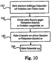
In einigen Ausführungsformen enthält das Substrat ein Ziel-Substrat, und enthält das Bedrucken der Mehrzahl von elektronischen Bauteilen auf das Ziel-Substrat: ein Bereitstellen der Mehrzahl von elektronischen Bauteilen, durch jeweilige Anbindeelemente am Quellen-Substrat lösbar angeheftet; ein Drücken eines Stempels auf das Quellen-Substrat, um die jeweiligen Anbindeelemente zu zerbrechen und die erste Fläche von jedem der elektronischen Bauteile an den Stempel anzukleben; ein Ausrichten des Stempels, welcher die Mehrzahl von elektronischen Bauteilen darauf enthält, zu den elektrischen Kontakten auf der Fläche des Ziel-Substrats; ein Drücken des Stempels auf das Ziel-Substrat, derart, dass das leitfähige Element auf der zweiten Fläche von jedem der elektronischen Bauteile mit einem jeweiligen der elektrischen Kontakte auf der Fläche des Ziel-Substrats in Kontakt tritt; und ein Trennen des Stempels vom Ziel-Substrat, um die Mehrzahl von elektrischen Bauteilen darauf zu bedrucken.In some embodiments, the substrate includes a target substrate, and printing the plurality of electronic components on the target substrate includes: providing the plurality of electronic components releasably attached to the source substrate by respective tie-downs; pressing a stamp on the source substrate to break the respective tether and glue the first surface of each of the electronic components to the stamp; aligning the stamper containing the plurality of electronic components thereon with the electrical contacts on the surface of the target substrate; pressing the stamp on the target substrate such that the conductive element on the second surface of each of the electronic components contacts a respective one of the electrical contacts on the surface of the target substrate; and separating the stamp from the target substrate to print the plurality of electrical components thereon.
In einigen Ausführungsformen enthält das Bereitstellen der Mehrzahl von elektronischen Bauteilen: ein Bereitstellen des Quellen-Substrats, welches eine Opfer-Schicht (engl.: sacrificial layer) darauf und die aktive Schicht auf der Opfer-Schicht enthält; ein Verarbeiten der aktiven Schicht, um die Mehrzahl von elektronischen Bauteilen, welche jeweils das zumindest eine aktive Element enthalten, auf der ersten Fläche davon zu bestimmen, wobei sich jeweilige Einschnitte (engl.: trenches) um jedes der elektronischen Bauteile erstrecken, und wobei die jeweiligen Anbindeelemente jedes der elektronischen Bauteile mit jeweiligen Ankerabschnitten der aktiven Schicht verbinden; und ein Entfernen von Abschnitten der Opfer-Schicht zwischen der Mehrzahl von elektronischen Bauteilen und dem Quellen-Substrat, so dass die Mehrzahl von elektronischen Bauteilen durch die jeweiligen Anbindeelemente entnehmbar an dem Quellen-Substrat angeklebt werden.In some embodiments, providing the plurality of electronic components includes: providing the source substrate including a sacrificial layer thereon and the active layer on the sacrificial layer; processing the active layer to determine the plurality of electronic components, each including the at least one active element, on the first surface thereof, with respective trenches extending around each of the electronic components, and wherein the connecting respective attachment elements of each of the electronic components to respective anchor portions of the active layer; and removing portions of the sacrificial layer between the plurality of electronic components and the source substrate, so that the plurality of electronic components are removably adhered to the source substrate by the respective attachment elements.
In einigen Ausführungsformen ist das Drücken des Stempels auf das Ziel-Substrat gefolgt durch ein Bereitstellen von einer Klebeschicht zwischen der zweiten Fläche von jedem der elektronischen Bauteile und der Fläche des Ziel-Substrats.In some embodiments, pressing the stamp onto the target substrate is followed by providing an adhesive layer between the second surface of each of the electronic components and the surface of the target substrate.
In einigen Ausführungsformen enthält die Klebeschicht eine leitfähige Schicht, welche zwischen dem leitfähigen Element von jedem der elektronischen Bauteile und den jeweiligen der elektrischen Kontakte auf dem Ziel-Substrat bereitgestellt wird.In some embodiments, the adhesive layer includes a conductive layer which is provided between the conductive element of each of the electronic components and the respective one of the electrical contacts on the target substrate.
In einigen Ausführungsformen ist das Trennen des Stempels vom Ziel-Substrat gefolgt durch ein Aushärten der Klebeschicht, um die Mehrzahl von elektronischen Bauteilen am Ziel-Substrat anzukleben, wobei eine Klebestärke der Klebeschicht größer ist als jene, welche dazu verwendet wird, um die erste Fläche von jedem der elektronischen Bauteile am Stempel anzukleben.In some embodiments, separating the stamp from the target substrate is followed by curing the adhesive layer to adhere the plurality of electronic components to the target substrate, an adhesive strength of the adhesive layer being greater than that used to form the first surface to stick each of the electronic components on the stamp.
In einigen Ausführungsformen enthält die Klebeschicht ein Material, welches zum Übergang zwischen einem nicht leitfähigen Zustand und einem leitfähigen Zustand in Ansprechen auf dessen Aushärtung ausgelegt ist.In some embodiments, the adhesive layer contains a material that is designed to transition between a non-conductive state and a conductive state in response to its curing.
In einigen Ausführungsformen enthält das Aushärten ein selektives Bestrahlen von Abschnitten der Klebeschicht durch das Ziel-Substrat, den Stempel und/oder die elektronischen Bauteile, unter Verwendung von Licht, Wärme und/oder elektromagnetischer Energie.In some embodiments, curing includes selectively irradiating portions of the adhesive layer through the target substrate, stamp, and / or electronic components using light, heat, and / or electromagnetic energy.
In einigen Ausführungsformen enthält die Klebeschicht eine eutektische Schicht, einen anisotropen leitfähigen Film und/oder leitfähige Nano-Partikel.In some embodiments, the adhesive layer contains a eutectic layer, an anisotropic conductive film and / or conductive nano-particles.
In einigen Ausführungsformen sind die leitfähigen Nano-Partikel in einem Kolloid bereitgestellt, und wird das Kolloid unter Verwendung von einem Tintenstrahl-Zerstäuber oder einem Mikro-Zerstäuber auf der Fläche des Ziel-Substrats abgelagert, um die Klebeschicht zu bestimmen.In some embodiments, the conductive nano-particles are provided in a colloid, and the colloid is deposited onto the surface of the target substrate using an inkjet atomizer or a micro-atomizer to define the adhesive layer.
In einigen Ausführungsformen enthält jedes der elektrischen Kontakte eine eutektische Schicht, und wird die eutektische Schicht nach dem Drücken des Stempels auf das Ziel-Substrat wiederaufgeschmolzen, so dass das leitfähige Element auf der zweiten Fläche von jedem der elektronischen Bauteile mit den jeweiligen der elektrischen Kontakte in Kontakt steht.In some embodiments, each of the electrical contacts includes a eutectic layer, and the eutectic layer is reflowed after the stamp is pressed onto the target substrate, so that the conductive element on the second surface of each of the electronic components with the respective one of the electrical contacts in Contact is available.
Gemäß weiterer Ausführungsformen der vorliegenden Erfindung enthält ein aktives Bauteilfeld: ein Ziel-Substrat, welches einen oder mehrere Kontakte hat, welche auf einer Seite des Ziel-Substrats ausgebildet sind; und ein oder mehrere aktive Bauteile, welche über dem Ziel-Substrat verteilt sind, wobei jedes aktive Bauteil eine aktive Schicht, welche eine Oberseite und eine gegenüberliegende Unterseite hat, und ein oder mehrere aktive Elemente, welche auf oder in der Oberseite der aktiven Schicht ausgebildet sind, enthält, wobei das aktive Element bzw. die aktiven Elemente elektrisch mit dem Kontakt bzw. den Kontakten verbunden ist bzw. sind, und wobei die Unterseite am Ziel-Substrat angeklebt ist.In accordance with further embodiments of the present invention, an active device array includes: a target substrate having one or more contacts formed on one side of the target substrate; and one or more active devices distributed over the target substrate, each active device having an active layer having a top and an opposite bottom, and one or more active elements formed on or in the top of the active layer wherein the active element (s) is or are electrically connected to the contact (s), and wherein the underside is adhered to the target substrate.
In einigen Ausführungsformen enthält das Feld ferner: einen Durchgang, welcher durch die aktive Schicht ausgebildet ist und über zumindest einem Kontakt positioniert ist und dazu ausgerichtet ist; und eine Metallschicht, welche auf zumindest einem Abschnitt des Durchgangs, welcher sich über zumindest einen Abschnitt der Oberseite des aktiven Bauteils erstreckt, ausgebildet ist, wobei die Metallschicht mit zumindest einem aktiven Element und zumindest einem Kontakt in elektrischer Verbindung steht.In some embodiments, the panel further includes: a via formed through the active layer and positioned over and aligned with at least one contact; and a metal layer which is formed on at least a portion of the passage that extends over at least a portion of the top side of the active component, the metal layer being in electrical connection with at least one active element and at least one contact.
In einigen Ausführungsformen enthält das Feld ferner eine Metallschicht, welche auf zumindest einem Abschnitt der Oberseite des aktiven Bauteils, der Seite des aktiven Bauteils und der Unterseite des aktiven Bauteils ausgebildet ist, wobei die Metallschicht mit zumindest einem aktiven Element und mit zumindest einem Kontakt in elektrischer Verbindung steht.In some embodiments, the field further contains a metal layer which is formed on at least a portion of the top side of the active component, the side of the active component and the bottom side of the active component, the metal layer having at least one active element and with at least one contact in electrical Connection.
In einigen Ausführungsformen enthält die aktive Schicht eine erste dotierte Halbleiterschicht, welche auf der Unterseite des aktiven Bauteils ausgebildet ist, eine Halbleiterschicht, welche zwischen dem ersten dotierten Halbleiter und dem aktiven Element bzw. den aktiven Elementen ausgebildet ist, und eine zweite dotierte Halbleiterschicht, welche zwischen dem Halbleiter und dem aktiven Element bzw. den aktiven Elementen ausgebildet ist, wobei die zweite dotierte Halbleiterschicht mit einer Ladung dotiert ist, welche entgegengesetzt ist zur dotierten Ladung der ersten dotierten Halbleiterschicht.In some embodiments, the active layer includes a first doped semiconductor layer which is formed on the underside of the active component, a semiconductor layer which is formed between the first doped semiconductor and the active element (s), and a second doped semiconductor layer which is formed between the semiconductor and the active element or the active elements, wherein the second doped semiconductor layer is doped with a charge which is opposite to the doped charge of the first doped semiconductor layer.
In einigen Ausführungsformen enthält das Feld ferner eine gemusterte Schicht, welche über zumindest einem Abschnitt des aktiven Bauteils und über zumindest einem Abschnitt des Ziel-Substrats ausgebildet ist, wobei die gemusterte Schicht mit dem aktiven Element bzw. den aktiven Elementen in elektrischer Verbindung steht. In einigen Ausführungsformen bildet die gemusterte Schicht leitfähige Führungen, welche mit einem aktiven Element im elektrischen Kontakt stehen.In some embodiments, the panel further includes a patterned layer formed over at least a portion of the active component and over at least a portion of the target substrate, the patterned layer being in electrical communication with the active element (s). In some embodiments, the patterned layer forms conductive guides that are in electrical contact with an active element.
In einigen Ausführungsformen enthält das Feld ferner ein Klebemittel, welches über zumindest einem Abschnitt des aktiven Bauteils und zumindest einem Abschnitt des Ziel-Substrats, welches vom aktiven Bauteil getrennt ist, ausgebildet ist.In some embodiments, the panel further includes an adhesive formed over at least a portion of the active component and at least a portion of the target substrate that is separate from the active component.
In einigen Ausführungsformen enthält das Feld ferner ein elektrisch leitfähiges Material, welches zwischen der Metallschicht und einem Kontakt positioniert ist und hiermit in elektrischer Verbindung steht.In some embodiments, the field further includes an electrically conductive material which is positioned between the metal layer and a contact and is in electrical communication therewith.
In einigen Ausführungsformen klebt das elektrisch leitfähige Material das aktive Bauteil an das Ziel-Substrat.In some embodiments, the electrically conductive material adheres the active component to the target substrate.
In einigen Ausführungsformen ist das elektrisch leitfähige Material ein eutektisches Material.In some embodiments, the electrically conductive material is a eutectic material.
In einigen Ausführungsformen ist das elektrisch leitfähige Material ein ungemusterter, anisotrop leitfähiger Film.In some embodiments, the electrically conductive material is an unpatterned, anisotropically conductive film.
In einigen Ausführungsformen enthält das aktive Element bzw. enthalten die aktiven Elemente eine elektronische Schaltung.In some embodiments, the active element or elements include electronic circuitry.
In einigen Ausführungsformen ist die aktive Schicht ein kristalliner Halbleiter.In some embodiments the active layer is a crystalline semiconductor.
Gemäß einer weiteren Ausführungsform der vorliegenden Erfindung enthält ein Verfahren zum Herstellen eines aktiven Bauteilfelds: ein Bereitstellen eines Ziel-Substrats, welches ein oder mehrere Kontakte hat, welche auf einer Seite des Substrats ausgebildet sind; ein Bereitstellen von einem oder mehreren aktiven Bauteilen, wobei jedes aktive Bauteil eine aktive Schicht, welche eine Oberseite und eine gegenüberliegende Unterseite hat, und ein oder mehrere aktive Elemente, welche auf oder in der Oberseite der aktiven Schicht ausgebildet sind, enthält, wobei das aktive Substrat eine elektrische Verbindung zwischen einem oder mehreren aktiven Elementen und einem Anschlussfeld (engl.: pad) auf der Rückseite der Aktiven hat; ein Verteilen des einen oder der mehreren aktiven Bauteile über dem Ziel-Substrat, wobei das Anschlussfeld über zumindest einem Kontakt positioniert ist und hierzu ausgerichtet ist; und ein Kleben der Unterseite an das Ziel-Substrat.In accordance with another embodiment of the present invention, a method of fabricating an active device pad includes: providing a target substrate having one or more contacts formed on a side of the substrate; providing one or more active devices, each active device including an active layer having a top and an opposite bottom, and one or more active elements formed on or in the top of the active layer, the active Substrate has an electrical connection between one or more active elements and a pad on the back of the active; distributing the one or more active components over the target substrate, wherein the connection pad is positioned over at least one contact and is aligned therewith; and gluing the bottom to the target substrate.
In einigen Ausführungsformen enthält das Verfahren ferner ein Ausbilden eines Durchgangs von der Oberseite zur Unterseite durch die aktive Schicht, ein Ausbilden des Anschlussfeldes mit einer Metallschicht über zumindest einem Abschnitt des Durchgangs im elektrischen Kontakt mit zumindest einem aktiven Element.In some embodiments, the method further includes forming a via from top to bottom through the active layer, forming the connection pad with a metal layer over at least a portion of the via in electrical contact with at least one active element.
In einigen Ausführungsformen ist die aktive Schicht aus einem Halbleitermaterial ausgebildet, und enthält das Verfahren ferner ein Ausbilden einer ersten dotierten Halbleiterschicht auf der Unterseite des aktiven Bauteils, ein Ausbilden einer Halbleiterschicht zwischen dem ersten dotierten Halbleiter und dem aktiven Element bzw. den aktiven Elementen, und ein Ausbilden einer zweiten dotierten Halbleiterschicht zwischen dem Halbleiter und dem aktiven Element bzw. den aktiven Elementen, wobei die zweite dotierte Halbleiterschicht mit einer Ladung dotiert ist, welche entgegengesetzt ist zur dotierten Ladung der ersten dotierten Halbleiterschicht.In some embodiments, the active layer is formed from a semiconductor material, and the method further includes forming a first doped semiconductor layer on the underside of the active component, forming a semiconductor layer between the first doped semiconductor and the active element or elements, and forming a second doped semiconductor layer between the semiconductor and the active element or elements, wherein the second doped semiconductor layer is doped with a charge which is opposite to the doped charge of the first doped semiconductor layer.
In einigen Ausführungsformen enthalten das Bereitstellen und Verteilen des einen oder der mehreren aktiven Bauteile über das Ziel-Substrat ferner ein Bereitstellen eines aktiven Substrats, welches eine Opfer-Schicht, welche über dem aktiven Substrat ausgebildet ist, und eine aktive Schicht, welche auf der Opfer-Schicht ausgebildet ist, hat; ein Verarbeiten des aktiven Substrats, um ein oder mehrere aktive Bauteile, welche ein aktives Element bzw. aktive Elemente haben, in oder auf der aktiven Schicht, eine elektrische Verbindung in elektrischer Verbindung mit einem oder mehreren aktiven Elementen und einem Anschlussfeld, welches auf der Unterseite der aktiven Schicht positioniert ist, und einen Einschnitt um jedes der aktiven Bauteile auszubilden, wobei sich der Einschnitt durch die aktive Schicht zur Opfer-Schicht erstreckt, wodurch getrennte aktive Bauteile ausgebildet werden; ein Entfernen der Opfer-Schicht mit Ausnahme von brechbaren Anbindeelementen, um die aktiven Bauteile von einem Rest des aktiven Substrats freizugeben; ein Drücken eines Stempels gegen die Oberseite von einem aktiven Bauteil bzw. aktiven Bauteilen, um somit die Anbindeelemente zu zerbrechen und die aktiven Bauteile an den Stempel anzukleben; und ein Drücken der aktiven Bauteile gegen das Ziel-Substrat in Ausrichtung zu den Kontakten, um die aktiven Bauteile an das Ziel-Substrat anzukleben.In some embodiments, providing and distributing the one or more active devices over the target substrate further includes providing an active substrate that has a sacrificial layer formed over the active substrate and an active layer that is formed on the sacrifice Layer is formed, has; processing the active substrate to form one or more active components having an active element or elements in or on the active layer, an electrical connection in electrical communication with one or more active elements, and a connection pad which is on the underside the active layer is positioned and an incision is formed around each of the active devices, the incision extending through the active layer to the sacrificial layer, thereby forming separate active devices; removing the sacrificial layer with the exception of frangible tie elements to expose the active components from a remainder of the active substrate; pressing a stamp against the top of an active component or active components, thus breaking the connecting elements and adhering the active components to the stamp; and pressing the active components against the target substrate in alignment with the contacts to adhere the active components to the target substrate.
In einigen Ausführungsformen enthält das Verfahren ferner ein Bereitstellen eines elektrisch leitfähigen Klebemittels über dem Ziel-Substrat oder aktiven Bauteilen, bevor die aktiven Bauteile gegen das Ziel-Substrat gedrückt werden.In some embodiments, the method further includes providing an electrically conductive adhesive over the target substrate or active components prior to pressing the active components against the target substrate.
In einigen Ausführungsformen wird das elektrisch leitfähige Klebemittel ausgehärtet, um das aktive Bauteil bzw. die aktiven Bauteile an das Ziel-Substrat anzukleben.In some embodiments, the electrically conductive adhesive is cured to adhere the active component (s) to the target substrate.
In einigen Ausführungsformen ist das elektrisch leitfähige Klebemittel ein eutektisches Material, ein anisotrop leitfähiger Film oder ein Kolloid, welches metallische Nano-Partikel enthält.In some embodiments, the electrically conductive adhesive is a eutectic material, an anisotropically conductive film, or a colloid containing metallic nano-particles.
In einigen Ausführungsformen enthält das Verfahren ferner ein Ablagern des Kolloids in einem Muster mit einem Tintenstrahl-Zerstäuber oder Mikro-Zerstäuber.In some embodiments, the method further includes depositing the colloid in a pattern with an ink jet atomizer or micro-atomizer.
In einigen Ausführungsformen enthält das Verfahren ferner ein Aushärten der metallischen Nano-Partikel mit einem Laser, um einen elektrischen Leiter auszubilden.In some embodiments, the method further includes curing the metallic nano-particles with a laser to form an electrical conductor.
In einigen Ausführungsformen wird die Aushärtung durch einen Laser durch das Ziel-Substrat, durch die aktive Schicht, einen Durchgang in der aktiven Schicht oder durch einen Stempel, welcher dazu verwendet wird, um die aktiven Bauteile an das Ziel-Substrat anzulegen, vorgenommen.In some embodiments, the curing is performed by a laser through the target substrate, through the active layer, a passage in the active layer or through a stamp which is used to apply the active components to the target substrate.
In einigen Ausführungsformen wird zumindest eine Metallschicht an zumindest einen Kontakt gelötet.In some embodiments, at least one metal layer is soldered to at least one contact.
In einigen Ausführungsformen enthält zumindest ein Kontakt ein eutektisches Material oder ist mit einem eutektischen Material beschichtet, und enthält das Verfahren ferner ein Wiederaufschmelzen des eutektischen Materials.In some embodiments, at least one contact contains or is coated with a eutectic material, and the method further includes remelting the eutectic material.
In einigen Ausführungsformen sind die aktiven Bauteile Aktiv-Matrix-Pixel-Steuerungen, lichtemittierende Dioden, Photo-Dioden, Kantenlaser oder photovoltaische Elemente.In some embodiments, the active components are active matrix pixel controllers, light emitting diodes, photo diodes, edge lasers or photovoltaic elements.
In einigen Ausführungsformen enthalten die Kontakte ein eutektisches Material oder haben eine eutektische Materialbeschichtung.In some embodiments, the contacts contain a eutectic material or have a eutectic material coating.
Ausführungsformen der vorliegenden Erfindung stellen aktive Bauteile mit hoher Leistung über große Substrate bei reduzierten Kosten hinsichtlich Materialien und beim Herstellungs-Equipment, mit geringeren Verarbeitungsschritten und Materialschichten, bereit.Embodiments of the present invention provide active components with high performance over large substrates at reduced costs in terms of materials and manufacturing equipment, with fewer processing steps and material layers.
Weitere Verfahren und/oder Vorrichtungen gemäß einigen Ausführungsformen werden dem Fachmann bei der Durchsicht der folgenden Zeichnung und detaillierten Beschreibung offensichtlich. Es ist beabsichtigt, dass alle solche zusätzlichen Ausführungsformen, zusätzlich zu einer jeglichen und allen Kombinationen der zuvor genannten Ausführungsformen, innerhalb dieser Beschreibung enthalten sind, innerhalb des Umfangs der Erfindung sind und durch die begleitenden Ansprüche geschützt sind.Other methods and / or devices in accordance with some embodiments will become apparent to those skilled in the art upon review of the following drawings and detailed description. It is intended that all such additional embodiments, in addition to any and all combinations of the aforementioned embodiments, be included within this specification, be within the scope of the invention, and be protected by the accompanying claims.
FigurenlisteFigure list
-
1A ist eine Schnittansicht, welche eine Ausführungsform der vorliegenden Erfindung darstellt, welche einen Durchgang hat;1A Fig. 13 is a sectional view showing an embodiment of the present invention having a passage; -
1B ist eine Schnittansicht, welche eine Ausführungsform der vorliegenden Erfindung darstellt, welche dotierte Halbleiterschichten hat;1B Fig. 13 is a sectional view showing an embodiment of the present invention having doped semiconductor layers; -
1C ist eine Schnittansicht, welche eine Ausführungsform der vorliegenden Erfindung darstellt, welche einen metallischen Leiter hat;1C Fig. 13 is a sectional view showing an embodiment of the present invention having a metallic conductor; -
2 ist eine Perspektivansicht der Vorrichtungselemente, dargestellt in der Schnittansicht von1A ;2 FIG. 13 is a perspective view of the device elements shown in the sectional view of FIG1A ; -
3 ist eine Schnittansicht, welche die Verwendung einer Isolierschicht auf einem Halbleiter gemäß einer Ausführungsform der vorliegenden Erfindung darstellt;3 Fig. 3 is a sectional view illustrating the use of an insulating layer on a semiconductor according to an embodiment of the present invention; -
4A und4B sind Schnittansichten, welche eine gemusterte Schicht enthalten, welche eine weitere Ausführungsform der vorliegenden Erfindung darstellen;4A and4B Fig. 13 are sectional views including a patterned layer which are another embodiment of the present invention; -
5 ist eine Draufsicht, welche den Aufbau von4A und4B darstellt;5 FIG. 13 is a plan view showing the structure of FIG4A and4B represents; -
6A ist eine Schnittansicht, welche ein gemustertes, elektrisch leitfähiges Material gemäß einer Ausführungsform der vorliegenden Erfindung enthält;6A Fig. 3 is a sectional view including a patterned electrically conductive material according to an embodiment of the present invention; -
6B ist eine Schnittansicht, welches ein ungemustertes, elektrisch leitfähiges Material gemäß einer weiteren Ausführungsform der vorliegenden Erfindung enthält;6B Fig. 13 is a sectional view including an unpatterned electrically conductive material according to another embodiment of the present invention; -
6C ist eine Schnittansicht, welche gemusterte, gesinterte Nano-Partikel gemäß einer weiteren Ausführungsform der vorliegenden Erfindung enthält;6C Fig. 13 is a sectional view including patterned sintered nano-particles according to another embodiment of the present invention; -
6D ist eine Schnittansicht, welche die Belichtung eines ungemusterten, elektrisch leitfähigen Materials durch eine Maske gemäß einer Ausführungsform der vorliegenden Erfindung darstellt;6D Figure 13 is a sectional view illustrating exposure of an unpatterned electrically conductive material through a mask in accordance with an embodiment of the present invention; -
6E ist eine Schnittansicht, welche die gemusterte Belichtung eines ungemusterten, elektrisch leitfähigen Materials gemäß einer Ausführungsform der vorliegenden Erfindung darstellt;6E Figure 13 is a sectional view illustrating patterned exposure of an unpatterned electrically conductive material in accordance with an embodiment of the present invention; -
6F ist eine Schnittansicht, welche eine Ausführungsform der vorliegenden Erfindung, welche ein eutektisches Material enthält, vor einem Wiederaufschmelzen darstellt;6F Fig. 13 is a sectional view showing an embodiment of the present invention containing a eutectic material prior to remelting; -
6G ist eine Schnittansicht, welche eine Ausführungsform der vorliegenden Erfindung, welche ein eutektisches Material enthält, nach einem Wiederaufschmelzen darstellt;6G Fig. 13 is a sectional view showing an embodiment of the present invention containing a eutectic material after remelting; -
7 ist ein Flussdiagramm, welches eine Ausführungsform des Verfahrens der vorliegenden Erfindung darstellt;7th Figure 3 is a flow diagram illustrating one embodiment of the method of the present invention; -
8A -8D sind Flussdiagramme, welche Abschnitte von verschiedenen Verfahren der vorliegenden Erfindung darstellen;8A -8D are flow charts depicting portions of various methods of the present invention; -
9 ist ein Flussdiagramm, welches eine alternative Ausführungsform des Verfahrens gemäß der vorliegenden Erfindung darstellt;9 Figure 3 is a flow diagram illustrating an alternative embodiment of the method according to the present invention; -
10 ist ein Flussdiagramm, welches die Verwendung eines elektrisch leitfähigen Klebemittels in einer alternativen Ausführungsform des Verfahrens der vorliegenden Erfindung darstellt;10 Figure 3 is a flow diagram illustrating the use of an electrically conductive adhesive in an alternative embodiment of the method of the present invention; -
11A -11G sind Schnittansichten der Elemente von aktiven Bauteilen bei unterschiedlichen Aufbaustufen gemäß einer Ausführungsform des Verfahrens der vorliegenden Erfindung;11A -11G -
12 ist eine Draufsicht, welche den Aufbau von11G darstellt;12 FIG. 13 is a plan view showing the structure of FIG11G represents; -
13A -13C sind Schnittansichten der Metallschicht in einem Durchgang bei unterschiedlichen Aufbaustufen gemäß einer Ausführungsform des Verfahrens der vorliegenden Erfindung;13A -13C -
14 ist eine Schnittansicht, welche dotierte Halbleiterschichten gemäß einer Ausführungsform der vorliegenden Erfindung darstellt;14th Fig. 3 is a sectional view illustrating doped semiconductor layers according to an embodiment of the present invention; -
15 ist ein Flussdiagramm, welches ein experimentelles Verfahren gemäß einer alternativen Ausführungsform des Verfahrens der vorliegenden Erfindung darstellt;15th Figure 3 is a flow diagram illustrating an experimental method in accordance with an alternative embodiment of the method of the present invention; -
16 ist eine Schnittansicht, welche eine experimentelle Vorrichtung darstellt, welche gemäß einer Ausführungsform der vorliegenden Erfindung erstellt ist;16 Fig. 13 is a sectional view showing an experimental apparatus made according to an embodiment of the present invention; -
17 ist eine Fotografie einer experimentellen Vorrichtung, welche gemäß einer Ausführungsform der vorliegenden Erfindung erstellt ist; und17th Fig. 3 is a photograph of an experimental device made in accordance with an embodiment of the present invention; and -
18 ist eine Fotografie der experimentellen Vorrichtung von17 , welche ein Licht emittiert.18th is a photograph of the experimental device from17th which emits a light.
Die Figuren sind nicht skaliert gezeichnet, da die einzelnen Elemente der Zeichnung eine zu große Größenschwankung haben, um eine skalierte Anzeige zuzulassen.The figures are not drawn to scale because the individual elements of the drawing have too great a fluctuation in size to allow a scaled display.
GENAUE BESCHREIBUNG VON AUSFÜHRUNGSFORMEN DER ERFINDUNGDETAILED DESCRIPTION OF EMBODIMENTS OF THE INVENTION
Die vorliegende Erfindung wird nun im Folgenden vollständiger mit Bezug auf die begleitende Zeichnung beschrieben, in welcher Ausführungsformen der Erfindung gezeigt sind. Diese Erfindung sollte jedoch nicht als auf die hier im Folgenden dargelegten Ausführungsformen beschränkt angesehen werden. Vielmehr sind diese Ausführungsformen derart bereitgestellt, dass diese Offenbarung umfassend und vollständig sein wird und dem Fachmann den Umfang der Erfindung vollständig vermitteln wird. In der Zeichnung ist die Dicke der Schichten und Bereiche aus Gründen der Klarheit überhöht. Gleiche Bezugszeichen beziehen sich durchweg auf gleiche Elemente.The present invention now will be described more fully hereinafter with reference to the accompanying drawings, in which embodiments of the invention are shown. This invention however, it should not be construed as being limited to the embodiments set forth below. Rather, these embodiments are provided so that this disclosure will be thorough and complete, and will fully convey the scope of the invention to those skilled in the art. In the drawing, the thickness of the layers and areas is exaggerated for the sake of clarity. The same reference numbers refer to the same elements throughout.
Es ist zu verstehen, dass, wenn ein Element, wie beispielsweise eine Schicht, ein Bereich oder ein Substrat, als „auf“ oder erstreckend „über“ einem weiteren Element bezeichnet ist, dieses direkt auf oder direkt über dem weiteren Element erstreckend sein kann, oder dass ebenso Zwischenelemente vorliegen können. Im Gegensatz dazu, wenn ein Element als „direkt auf“ oder sich „direkt über“ einem weiteren Element erstreckend bezeichnet ist, liegen keine Zwischenelemente vor. Es wird ebenso verständlich sein, dass, wenn ein Element als „in Kontakt mit“ oder „verbunden mit“ oder „gekoppelt mit“ einem weiteren Element bezeichnet ist, dieses direkt in Kontakt oder verbunden mit oder gekoppelt mit dem weiteren Element sein kann, oder dass Zwischenelemente vorliegen können. Im Gegensatz dazu, wenn ein Element als „im direkten Kontakt mit“ oder „direkt verbunden mit“ oder „direkt gekoppelt mit“ einem weiteren Element bezeichnet ist, liegen keine Zwischenelemente vor.It is to be understood that when an element, such as a layer, area or substrate, is referred to as being "on" or extending "over" another element, it can extend directly onto or directly over the further element, or that intermediate elements can also be present. In contrast, when an element is referred to as extending "directly on" or "directly over" another element, there are no intermediate elements. It will also be understood that when an element is referred to as being “in contact with” or “connected to” or “coupled to” another element, that element may be directly in contact with or connected to or coupled to the further element, or that intermediate elements can be present. In contrast, when an element is referred to as “in direct contact with” or “directly connected to” or “directly coupled to” another element, there are no intermediate elements.
Es wird ebenso verständlich sein, dass, obwohl die Ausdrücke erstes, zweites, usw., hier verwendet werden können, um verschiedene Elemente zu beschreiben, diese Elemente nicht durch diese Ausdrücke beschränkt werden sollten. Diese Ausdrücke werden lediglich dazu verwendet, um ein Element von einem anderen zu unterscheiden. Beispielsweise kann ein erstes Element als ein zweites Element ausgedrückt werden, und kann ähnlich ein zweites Element als ein erstes Element ausgedrückt werden, ohne vom Umfang der vorliegenden Erfindung abzuweichen.It will also be understood that although the terms first, second, etc. may be used herein to describe various elements, those elements should not be limited by these terms. These terms are only used to distinguish one element from another. For example, a first element can be expressed as a second element and similarly a second element can be expressed as a first element without departing from the scope of the present invention.
Ferner können relative Ausdrücke, wie beispielsweise „untere“ oder „Unterseite“ und „obere“ oder „Oberseite“, hier verwendet werden, um eine Beziehung eines Elements zu einem weiteren Element, wie in den Figuren dargestellt, zu beschreiben. Es wird verständlich sein, dass relative Ausdrücke dazu beabsichtigt sind, um unterschiedliche Ausrichtungen der Vorrichtung, zusätzlich zu der in den Figuren angezeigten Ausrichtung, einzuschließen. Wenn beispielsweise die Vorrichtung in einer der Figuren umgedreht wird, werden Elemente, welche als auf der „unteren“ Seite von weiteren Elementen beschrieben sind, dann auf „oberen“ Seiten von den weiteren Elementen ausgerichtet sein. Der beispielhafte Ausdruck „untere“ kann daher sowohl eine Ausrichtung von „untere“ also auch „obere“, in Abhängigkeit von der bestimmten Ausrichtung von der Figur, umfassen. Ähnlich gilt, dass, wenn die Vorrichtung in einer der Figuren umgedreht wird, jene Elemente, welche als „unter“ oder „unterhalb“ von weiteren Elementen beschrieben sind, dann „oberhalb“ der weiteren Elemente ausgerichtet sein werden. Der beispielhafte Ausdruck „unter“ oder „unterhalb“ kann daher sowohl eine Ausrichtung von über als auch unter umfassen.Furthermore, relative expressions such as “lower” or “lower side” and “upper” or “upper side” can be used here to describe a relationship of one element to another element, as shown in the figures. It will be understood that relative terms are intended to encompass different orientations of the device in addition to the orientation indicated in the figures. For example, if the device in one of the figures is turned over, elements described as being on the "lower" side of further elements will then be aligned on "upper" sides of the further elements. The exemplary expression “lower” can therefore include both an alignment of “lower” and also “upper”, depending on the specific alignment of the figure. Similarly, if the device in one of the figures is turned over, those elements which are described as “below” or “below” of further elements will then be oriented “above” the further elements. The exemplary expression “below” or “below” can therefore encompass both an alignment of above and below.
Die hier in der Beschreibung von der Erfindung verwendete Terminologie dient lediglich zum Zwecke der Beschreibung von bestimmten Ausführungsformen, und ist nicht als die Erfindung beschränkend beabsichtigt. Wie in der Beschreibung von der Erfindung und den anliegenden Ansprüchen verwendet, sind die Singularformen „ein“, „eine“ und „der/die/das“ dazu beabsichtigt, ebenso die Pluralformen zu enthalten, es sei denn, dass der Kontext klar das Gegenteil anzeigt. Es wird ebenso verständlich sein, dass der Ausdruck „und/oder“, wie hier verwendet, sich auf Kombinationen von einem oder mehreren der zugehörig aufgelisteten Elemente bezieht und eine jegliche und alle möglichen Kombinationen hiervon einschliesst. Es wird ferner verständlich sein, dass die Ausdrücke „enthält“ und/oder „enthaltend“, wenn in diesen Anmeldeunterlagen verwendet, das Vorliegen von angegebenen Merkmalen, Ganzzahlen, Schritten, Betrieben, Elementen und/oder Bauteilen spezifizieren, jedoch nicht das Vorliegen oder die Hinzufügung von einem oder mehreren weiteren Merkmalen, Ganzzahlen, Schritten, Betrieben, Elementen, Bauteilen und/oder Gruppen davon ausschließen.The terminology used herein in describing the invention is for the purpose of describing particular embodiments only and is not intended to be limiting of the invention. As used in the description of the invention and the appended claims, the singular forms “a”, “an” and “the” are intended to include the plural forms as well, unless the context clearly states the contrary indicates. It will also be understood that the term “and / or” as used herein refers to combinations of one or more of the associated listed items and includes any and all possible combinations thereof. It will also be understood that the terms "contains" and / or "containing" when used in these filing documents specify the presence of any indicated features, integers, steps, operations, elements and / or components, but not the presence or absence Exclude the addition of one or more additional characteristics, integers, steps, operations, elements, components and / or groups thereof.
Es sind hier Ausführungsformen der Erfindung mit Bezug auf QuerschnittsDarstellungen beschrieben, welche schematische Darstellungen von idealisierten Ausführungsformen (und Zwischenaufbauten) der Erfindung sind. Somit sind Abweichungen von den Formen der Darstellungen, resultierend beispielsweise aus Herstellungstechniken und/oder Toleranzen, zu erwarten. Somit sollten Ausführungsformen der Erfindung nicht als auf die bestimmten Formen von Bereichen, wie hier dargestellt, beschränkt angesehen werden, sondern enthalten sie Abweichungen von Formen, welche beispielsweise aus der Herstellung resultieren. Mit anderen Worten, sind die in den Figuren dargestellten Bereiche in der Natur schematisch, und dienen ihre Formen nicht dazu, die aktuelle Form eines Bereiches von einer Vorrichtung darzustellen, und dienen sie nicht dazu den Umfang der Erfindung zu beschränken.Embodiments of the invention are described herein with reference to cross-sectional representations which are schematic representations of idealized embodiments (and intermediate structures) of the invention. Deviations from the shapes of the representations, resulting, for example, from manufacturing techniques and / or tolerances, are therefore to be expected. Thus, embodiments of the invention should not be viewed as limited to the specific shapes of areas as shown here, but rather contain deviations from shapes that result, for example, from manufacture. In other words, the areas shown in the figures are schematic in nature and their shapes do not serve to represent the actual shape of any area of a device and do not serve to limit the scope of the invention.
Falls nicht anders definiert, haben alle Ausdrücke, welche bei der Offenbarung von Ausführungsformen der Erfindung verwendet werden, einschließlich technischer und wissenschaftlicher Ausdrücke, die gleiche Bedeutung wie allgemein durch den Fachmann verständlich, an welchen diese Erfindung gerichtet ist, und sind nicht notwendigerweise auf die spezifischen Definitionen beschränkt, welche zum Zeitpunkt der beschriebenen vorliegenden Erfindung bekannt sind. Demgemäß können diese Ausdrücke äquivalente Ausdrücke einschließen, welche nach einer solchen Zeit geschaffen werden. Es wird ferner verständlich sein, dass Ausdrücke, wie jene, welche in den allgemein verwendeten Wörterbüchern definiert sind, derart interpretiert werden sollten, dass sie eine Bedeutung haben, welche mit ihrer Bedeutung in den vorliegenden Anmeldeunterlagen und im Kontext des Standes der Technik konsistent ist, und nicht in einem idealisierten oder übermäßig formalen Sinne interpretiert werden wird, es sei denn, dass dies hier ausdrücklich so definiert ist. Alle Veröffentlichungen, Patentanmeldungen, Patente und weitere Referenzen, wie hier erwähnt, sind in ihrer Gänze durch Inbezugnahme einbezogen.Unless otherwise defined, all terms used in the disclosure of embodiments of the invention, including technical and scientific terms, have the same meaning as generically those skilled in the art to which this invention pertains will be understood and are not necessarily limited to the specific definitions known at the time of the present invention described. Accordingly, these terms may include equivalent terms created after such time. It will also be understood that terms such as those defined in the dictionaries commonly used should be interpreted to have a meaning that is consistent with their meaning in the present application and in the context of the prior art, and will not be interpreted in an idealized or overly formal sense unless specifically defined herein. All publications, patent applications, patents and other references as mentioned herein are incorporated in their entirety by reference.
Unter Bezugnahme auf
Wie hier verwendet, ist ein aktives Bauteilfeld (hier ebenso als ein aktives Bauteil bezeichnet) ein jegliches Substrat, welches darauf positionierte aktive Bauteile hat. Die aktiven Bauteile können elektronische Schaltungen, Berechnungsschaltungen oder optische Elemente, welche Licht entweder emittieren oder absorbieren, enthalten. Die Schaltungen können entweder analog oder digital sein und können Transistoren, Kondensatoren, Widerstände oder weitere elektronische Elemente enthalten. Das aktive Bauteilfeld kann verschiedenartige Bauteile enthalten, welche entweder regelmäßig oder unregelmäßig über das Ziel verteilt sind. Substrate können Glas, Polymer, Metall oder einen Halbleiter, beispielsweise Silizium, GaAs oder weitere III-V Materialien umfassen.As used herein, an active device array (also referred to herein as an active device) is any substrate that has active devices positioned thereon. The active components can contain electronic circuits, computing circuits, or optical elements which either emit or absorb light. The circuits can be either analog or digital and can contain transistors, capacitors, resistors or other electronic elements. The active component field can contain components of various types, which are distributed either regularly or irregularly over the target. Substrates can include glass, polymer, metal or a semiconductor, for example silicon, GaAs or other III-V materials.
Bezugnehmend auf
Bezugnehmend auf
Bezugnehmend auf
Abermals Bezug nehmend auf
In einer in
Wie hier beschrieben, sind die aktiven Elemente, welche auf oder in der Oberseite von der aktiven Schicht ausgebildet sind, im Durchschnitt näher an der Oberseite als an der Unterseite. Die aktiven Elemente können sich nahe der Unterseite von der aktiven Schicht in die aktive Schicht erstrecken. Die aktive Schicht kann eine Halbleiterschicht sein, beispielsweise ein kristalliner Halbleiter, wie beispielsweise kristallines Silizium. Abschnitte der aktiven Elemente können auf der Oberseite von der aktiven Schicht ausgebildet sein, und können in Schichten innerhalb der aktiven Schicht ausgebildet sein, beispielsweise unter Verwendung von photolithographischen Prozessen, welche im Stand der Technik bezogen auf eine integrierte Schaltung bekannt sind. Im Allgemeinen ist, wie hier beschrieben, die Oberseite der aktiven Schicht gleich die Prozessseite der aktiven Schicht
In verschiedenen Ausführungsformen der vorliegenden Erfindung kann das aktive Bauteilfeld der vorliegenden Erfindung beispielsweise zur Ausbildung von einer Aktiv-Matrix verwendet werden, bei welcher die aktiven Bauteile in einem Feld organisiert sind, welches ein entsprechendes Feld von Elementen steuert, beispielsweise Pixel in einer Anzeige oder einer digitalen radiographischen Platte. In einem weiteren Beispiel können die aktiven Bauteile Licht-Emissionsquellen, beispielsweise lichtemittierende Dioden oder LEDs, oder ein Vertikal-Hohlraum Seitenemissionslaser (engl.: vertical cavity side-emission laser) (beispielsweise ein Kanten-Laser) sein. In einem weiteren Beispiel können die aktiven Bauteile dazu dienen, einfallendes Licht in Elektrizität umzuwandeln, wobei eine photovoltaische Vorrichtung, beispielsweise mit Photo-Dioden, ausgebildet wird. In various embodiments of the present invention, the active component field of the present invention can be used, for example, to form an active matrix in which the active components are organized in a field which controls a corresponding field of elements, for example pixels in a display or a digital radiographic plate. In a further example, the active components can be light-emission sources, for example light-emitting diodes or LEDs, or a vertical cavity side-emission laser (for example an edge laser). In a further example, the active components can serve to convert incident light into electricity, with a photovoltaic device, for example with photo diodes, being formed.
In Fällen, bei welchen es gewünscht ist, Licht wirksam einzusammeln oder zu emittieren, können die Kontakte oder jegliche Metallschichten, welche unterhalb von der aktiven Schicht ausgebildet sind, einfallendes Licht, welches durch das aktive Bauteil durchläuft, durch das aktive Bauteil zurückreflektieren. In dem Fall, bei welchem ein aktives Bauteil dazu dient, Licht in elektrischen Strom umzuwandeln, stellt diese Reflexion eine verbesserte Absorption von Licht durch das aktive Bauteil bereit. In dem Fall, bei welchem das aktive Bauteil Licht emittiert oder die Emission von Licht durch weitere Schichten steuert, stellt die Reflexion eine verbesserte Emission von Licht bereit.In cases where it is desired to efficiently collect or emit light, the contacts or any metal layers formed beneath the active layer can reflect incident light passing through the active component back through the active component. In the case where an active component is used to convert light into electrical current, this reflection provides an improved absorption of light by the active component. In the case in which the active component emits light or controls the emission of light through further layers, the reflection provides an improved emission of light.
Ferner Bezugnehmend auf
In einer Ausführungsform der vorliegenden Erfindung kann eine Metallschicht
Gemäß einer alternativen Ausführungsform der vorliegenden Erfindung kann eine elektrische Verbindung zwischen einem aktiven Element und dem Kontakt auf dem Ziel-Substrat erhöht werden, indem die elektrische Verbindung zwischen den Metallschichten und den Kontakten verbessert wird, indem ein elektrisch leitfähiges Material zwischen jeder Metallschicht und jedem Kontakt bereitgestellt wird.According to an alternative embodiment of the present invention, an electrical connection between an active element and the contact on the target substrate can be increased by improving the electrical connection between the metal layers and the contacts by adding an electrically conductive material between each metal layer and each contact provided.
Bezugnehmend auf
Alternativ kann, wie in
Alternativ, wie in
Der gemusterte elektrisch leitfähige Kontakt kann ein eutektisches Material
Es kann eine Vielzahl von Elementen dazu verwendet werden, um das elektrisch leitfähige Material
Das elektrisch leitfähige Material kann eine Vielzahl von Materialien enthalten. Insbesondere können eutektische Materialien, welche mehrere unterschiedliche Metalle zusammenfassen, verwendet werden, beispielsweise Mischungen aus Zinn und Blei, Mischungen aus Indium, Gold und Kupfer, Mischungen aus Gallium und Indium oder Mischungen aus Zinn, Silber und Kupfer. Die elektrisch leitfähigen Materialien können durch Siebdruck oder weitere Musterverfahren, welche photolithographische Verfahren oder Mikro-Zerstäuber-Verfahren enthalten, gemustert werden. In einer Ausführungsform der vorliegenden Erfindung können Nano-Metalle, beispielsweise Metallpartikel im Nanometerbereich aus beispielsweise Edelmetallen, Silber oder Gold, über beispielsweise einen Tintendrucker oder eine weitere Mikro-Zerstäuber-Muster-Applikation-Vorrichtung in einem Flüssigträger zerstäubt werden. Diese Materialien können durch Wärme, welche beispielsweise durch Heizen (engl.: baking) oder durch das gemusterte Anlegen von Energie, beispielsweise ein Laser, durch das Ziel-Substrat oder durch das aktive Bauteil zugeführt ist, ausgehärtet werden, um einen elektrisch leitfähigen, gesinterten, partikelförmigen Leiter auszubilden. In einer weiteren Ausführungsform der vorliegenden Erfindung kann eine Oxidschicht auf einem Metallkontakt ausgebildet werden. Sobald die Metallschicht zum Metallkontakt ausgerichtet ist und hierzu angrenzt, kann das gemusterte Anlegen von Energie auf den Metallkontakt ein Metall durch die Oxidschicht treiben, um eine elektrische Verbindung zwischen der Metallschicht und dem Metallkontakt auszubilden. Wie zuvor erwähnt, können die Metallschicht und der Kontakt gelötet werden.The electrically conductive material can include a variety of materials. In particular, eutectic materials which combine several different metals can be used, for example mixtures of tin and lead, mixtures of indium, gold and copper, mixtures of gallium and indium or mixtures of tin, silver and copper. The electrically conductive materials can be patterned by screen printing or other patterning processes which include photolithographic processes or micro-atomization processes. In one embodiment of the present invention, nano-metals, for example metal particles in the nanometer range of, for example, precious metals, silver or gold, can be atomized in a liquid carrier via, for example, an ink printer or another micro-atomizer pattern application device. These materials can be cured by heat, which is supplied for example by heating (English: baking) or by the patterned application of energy, for example a laser, through the target substrate or by the active component, to form an electrically conductive, sintered to form particulate conductors. In another embodiment of the present invention, an oxide layer can be formed on a metal contact. Once the metal layer is aligned with and adjacent to the metal contact, the patterned application of energy to the metal contact can drive a metal through the oxide layer to form an electrical connection between the metal layer and the metal contact. As mentioned before, the metal layer and the contact can be soldered.
Die Schritte zum Ausbilden der verschiedenen Elemente der vorliegenden Erfindung können, in Abhängigkeit von den Notwendigkeiten des Herstellungsprozesses und verschiedener Ausführungsformen der vorliegenden Erfindung, in unterschiedlichen Reihenfolgen durchgeführt werden. Bezug nehmend auf
In einer alternativen Ausführungsform der vorliegenden Erfindung kann, unter Bezugnahme auf
In einer weiteren alternativen Ausführungsform der vorliegenden Erfindung kann, unter Bezugnahme auf
In einem weiteren Verfahren der vorliegenden Erfindung, wie in
In einem weiteren Verfahren der vorliegenden Erfindung, wie in
Bezug nehmend auf
Nachdem die Opfer-Schicht und die aktive Schicht auf dem aktiven Substrat abgelagert sind, kann das aktive Substrat verarbeitet werden, um aktive Bauteile in oder auf der aktiven Schicht auszubilden, beispielsweise unter Verwendung von Silizium-Gießfabrikation-Prozessen. Es können zusätzliche Materialschichten als auch weitere Materialien, wie beispielsweise Metalle, Oxide, Nitride und weitere Materialien, welche im Stand der Technik in Bezug auf eine integrierte Schaltung bekannt sind, hinzugefügt werden. Jedes aktive Bauteil kann eine vollständige integrierte Schaltung aus Halbleiter sein und enthält beispielsweise Transistoren. Die aktiven Bauteile können unterschiedliche Größen haben, beispielsweise 1.000 µm2 oder 10.0000 µm2, 100.000 µm2 oder 1 mm2 oder größer, und können variable Längenverhältnisse haben, beispielsweise 2:1, 5:1 oder 10:1. Die aktiven Bauteile können eine Dicke von 5 - 20 µm, 20 - 50 µm oder 50 bis 100 µm haben. Substrate dieser Größe können typischerweise nicht unter Verwendung von herkömmlichen Techniken, wie beispielsweise Oberflächen-BefestigungsTechniken, gehandhabt werden.After the sacrificial layer and the active layer are deposited on the active substrate, the active substrate can be processed to form active components in or on the active layer, for example using silicon cast fabrication processes. Additional layers of material, as well as other materials, such as metals, oxides, nitrides, and other materials known in the art with respect to an integrated circuit, can be added. Each active component can be a complete integrated circuit made of semiconductor and contains, for example, transistors. The active components can have different sizes, for example 1,000 μm 2 or 10,000 μm 2 , 100,000 μm 2 or 1 mm 2 or larger, and can have variable length ratios, for example 2: 1, 5: 1 or 10: 1. The active components can have a thickness of 5 - 20 µm, 20 - 50 µm or 50 to 100 µm. Substrates of this size typically cannot be handled using conventional techniques, such as surface mount techniques.
Bezugnehmend auf
In einer alternativen Ausbildungsform können die Durchgänge in dem gleichen Schritt wie bei den Einschnitten ausgebildet werden, und werden die Metallschichten nachfolgend beschichtet. Die Opfer-Schicht
In einer anderen Ausführungsform der vorliegenden Erfindung können die Durchgänge vollständig mit Metall befüllt werden, um eine zusätzliche Leitfähigkeit und eine mechanische und umgebungsbedingte Robustheit bereitzustellen. Alternativ, unter Verwendung des Aufbaus von
Die Opfer-Schicht
Die Metallschicht
Abermals Bezugnehmend auf
Ein Verfahren zum Aushärten des elektrisch leitfähigen Klebemittels liegt im Aussetzen des Klebemittels in den gewünschten Positionen zwischen der Metallschicht und den Kontakten, hinsichtlich eines gemusterten elektromagnetischen Lichts, welches beispielsweise durch einen Laser bereitgestellt wird (wie in
In verschiedenen Ausführungsformen der vorliegenden Erfindung kann der Durchgang ausgebildet werden, bevor das eine oder die mehreren aktiven Bauteile über dem Ziel-Substrat verteilt werden oder nachdem das eine oder die mehreren aktiven Bauteile über dem Ziel-Substrat verteilt sind.In various embodiments of the present invention, the passage before the one or more active components are distributed over the target substrate or after the one or more active components are distributed over the target substrate.
Einige Ausführungsformen der vorliegenden Erfindung stellen ein aktives Substrat mit hoher Leistung mit einer reduzierten Anzahl von Schichten und Verarbeitungsschritten bereit, und welches robustere elektrische Zwischenverbindungen bereitstellt. In einigen Ausführungsformen der vorliegenden Erfindung sind die aktiven Bauteile kleine integrierte Schaltungen, welche in einem Halbleiter-Wafer-Substrat ausgebildet sind, beispielsweise Gallium-Arsenid oder Silizium, welches einen kristallinen Aufbau haben kann. Verarbeitungstechnologien für diese Materialien wenden typischerweise hohe Wärme und reaktive chemische Mittel an. Durch die Anwendung von Überführungs-Technologien, welche das aktive Bauteil oder Substratmaterialien nicht belasten, können jedoch, verglichen mit Dünnfilm-Transistor-Herstellungsprozessen, unkritischere Umgebungsbedingungen verwendet werden. Somit hat die vorliegende Erfindung einen Vorteil dahingehend, dass flexible Substrate (beispielsweise Polymer-Substrate), welche eine geringere Toleranz hinsichtlich von extremen Verarbeitungsbedingungen (beispielsweise Wärme, chemische Mittel oder mechanische Prozesse) haben, entweder für das aktive Substrat oder das Ziel-Substrat oder für beide verwendet werden können. Ferner wurde demonstriert, dass kristalline Silizium-Substrate starke mechanische Eigenschaften haben, und bei kleinen Größen relativ flexibel und tolerant in Bezug auf eine mechanische Belastung sein können, insbesondere bei Substraten mit Dicken von 5 µm, 10 µm, 20 µm, 50 µm oder sogar 100 µm. Alternativ kann die aktive Schicht eine mikrokristalline, polykristalline oder amorphe Halbleiterschicht sein.Some embodiments of the present invention provide a high performance active substrate with a reduced number of layers and processing steps, and which provides more robust electrical interconnections. In some embodiments of the present invention, the active components are small integrated circuits which are formed in a semiconductor wafer substrate, for example gallium arsenide or silicon, which can have a crystalline structure. Processing technologies for these materials typically employ high heat and reactive chemical agents. However, by using transfer technologies that do not stress the active component or substrate materials, less critical environmental conditions can be used compared to thin-film transistor manufacturing processes. Thus, the present invention has an advantage in that flexible substrates (e.g. polymer substrates), which have a lower tolerance to extreme processing conditions (e.g. heat, chemical means or mechanical processes), either for the active substrate or the target substrate or can be used for both. It has also been demonstrated that crystalline silicon substrates have strong mechanical properties and, in the case of small sizes, can be relatively flexible and tolerant of mechanical stress, especially in the case of substrates with thicknesses of 5 μm, 10 μm, 20 μm, 50 μm or even 100 µm. Alternatively, the active layer can be a microcrystalline, polycrystalline or amorphous semiconductor layer.
Sobald alle der aktiven Bauteile, welche in einem Prozess zu verwenden sind, überführt sind, kann das aktive Substrat von den verbleibenden Materialien der aktiven Schicht und der Opfer-Schicht abgelöst werden und gereinigt werden. Es kann eine zweite Opfer-Schicht über dem aktiven Substrat ausgebildet werden und eine zweite aktive Schicht über der zweiten Opfer-Schicht ausgebildet werden. Der Prozess zum Aufbauen von neuen aktiven Bauteilen kann dann wiederholt werden, wodurch das aktive Substrat wiederverwendet wird.As soon as all of the active components that are to be used in a process have been transferred, the active substrate can be detached from the remaining materials of the active layer and the sacrificial layer and cleaned. A second sacrificial layer can be formed over the active substrate and a second active layer can be formed over the second sacrificial layer. The process of building new active components can then be repeated, thereby reusing the active substrate.
Bei verschiedenen Verfahren der vorliegenden Erfindung werden Laserstrahlen dazu verwendet, um die elektrisch leitfähigen Klebebereiche zwischen den Kontakten und den Metallschichten selektiv auszuhärten. In einer Ausführungsform können die Klebebereiche sequenziell belichtet werden. In einer weiteren Ausführungsform können mehrere Bereiche gleichzeitig belichtet werden, wodurch die Anzahl von aktiven Bauteilen erhöht wird, welche gleichzeitig angeklebt werden. Ein alternatives Verfahren, welches eine Maske verwendet, kann ebenso mehrere aktive Bauteile auf einmal ankleben, wodurch die Rate erhöht wird, mit welcher Ziel-Substrate bestückt werden können. Es können Elemente, welche im Stand der Technik bekannt sind, zum Abtasten und Steuern von Lasern verwendet werden, als auch Lichtquellen, welche in Verbindung mit ausgerichteten Masken verwendet werden, insbesondere wie im Stand der Technik in Bezug auf Photolithographie bekannt.Various methods of the present invention use laser beams to selectively cure the electrically conductive adhesive areas between the contacts and the metal layers. In one embodiment, the adhesive areas can be exposed sequentially. In a further embodiment, several areas can be exposed at the same time, thereby increasing the number of active components which are glued on at the same time. An alternative method that uses a mask can also glue multiple active components at once, increasing the rate at which target substrates can be populated. Elements known in the art can be used to scan and control lasers, as well as light sources used in conjunction with aligned masks, particularly as known in the art relating to photolithography.
Im Vergleich zu Dünnfilm-Herstellungsverfahren, wird unter Verwendung von dicht bestücken aktiven Substraten und einem Überführen von aktiven Bauteilen auf ein Ziel-Substrat, welches lediglich ein kleines Feld von aktiven Bauteilen, welche darauf positioniert sind, erfordert, kein Material einer aktiven Schicht auf einem Ziel-Substrat verschwendet oder erfordert. Die vorliegende Erfindung ist ebenso nützlich beim Überführen von aktiven Bauteilen, welche aus kristallinen Halbleitermaterialien erstellt sind, welche eine viel höhere Leistung als dünnfilmige aktive Bauteile haben. Ferner werden die Anforderungen hinsichtlich Flachheit, Glattheit, chemischer Stabilität und Wärmestabilität für ein Ziel-Substrat, welches in der vorliegenden Erfindung nützlich ist, größtenteils reduziert, da der Anklebe- und Überführungs-Prozess durch die Materialeigenschaften des Ziel-Substrats nicht wesentlich beschränkt wird. Herstellungs- und Materialkosten werden aufgrund von hohen Verwendungsraten von teuren Materialien (beispielsweise das aktive Substrat) und reduzierten Material- und Verarbeitungsanforderungen für das Ziel-Substrat reduziert.Compared to thin film fabrication methods, using densely populated active substrates and transferring active devices to a target substrate which only requires a small array of active devices positioned thereon, no active layer material is deposited on top of one Target substrate wasted or required. The present invention is also useful in transferring active devices made from crystalline semiconductor materials which have much higher performance than thin film active devices. Furthermore, the flatness, smoothness, chemical stability and thermal stability requirements for a target substrate useful in the present invention are largely reduced because the sticking and transferring process is not significantly limited by the material properties of the target substrate. Manufacturing and material costs are reduced due to high usage rates of expensive materials (e.g. the active substrate) and reduced material and processing requirements for the target substrate.
In einer experimentellen Demonstration wurde der in
Sobald das Ziel-Substrat vorbereitet war, wurden aktive Bauteile vorbereitet, indem eine aktive Schicht über einer Opfer-Schicht auf einem aktiven, kristallinen GaAs Substrat ausgebildet wurde. Die aktiven Bauteile wurden vom aktiven Substrat freigegeben, indem die Opfer-Schicht, mit Ausnahme von Anbindeelementen, weggeätzt wurde, wie zuvor beschrieben. Ein PDMS Stempel wurde dazu verwendet, um die aktiven Bauteile vom aktiven Substrat zu trennen, wobei die Anbindeelemente zerbrochen wurden und die aktiven Bauteile in Schritt
Die vervollständigte experimentelle Vorrichtung wird in
Die gesamte Baugruppe, welche das Ziel-Substrat
Claims (32)
Applications Claiming Priority (3)
| Application Number | Priority Date | Filing Date | Title |
|---|---|---|---|
| US31852210P | 2010-03-29 | 2010-03-29 | |
| US61/318,522 | 2010-03-29 | ||
| PCT/US2011/029365 WO2011126726A1 (en) | 2010-03-29 | 2011-03-22 | Electrically bonded arrays of transfer printed active components |
Publications (3)
| Publication Number | Publication Date |
|---|---|
| DE112011101135T5 DE112011101135T5 (en) | 2013-03-14 |
| DE112011101135T8 DE112011101135T8 (en) | 2013-05-29 |
| DE112011101135B4 true DE112011101135B4 (en) | 2021-02-11 |
Family
ID=44120924
Family Applications (1)
| Application Number | Title | Priority Date | Filing Date |
|---|---|---|---|
| DE112011101135.0T Expired - Fee Related DE112011101135B4 (en) | 2010-03-29 | 2011-03-22 | Electrically connected fields of active components in transfer printing technology |
Country Status (3)
| Country | Link |
|---|---|
| US (2) | US9049797B2 (en) |
| DE (1) | DE112011101135B4 (en) |
| WO (1) | WO2011126726A1 (en) |
Cited By (1)
| Publication number | Priority date | Publication date | Assignee | Title |
|---|---|---|---|---|
| US11829074B2 (en) | 2017-04-13 | 2023-11-28 | X-Fab Semiconductor Foundries Gmbh | Geometrically shaped components in an assembly for a transfer print and associated methods |
Families Citing this family (100)
| Publication number | Priority date | Publication date | Assignee | Title |
|---|---|---|---|---|
| US8877648B2 (en) | 2009-03-26 | 2014-11-04 | Semprius, Inc. | Methods of forming printable integrated circuit devices by selective etching to suspend the devices from a handling substrate and devices formed thereby |
| US9161448B2 (en) * | 2010-03-29 | 2015-10-13 | Semprius, Inc. | Laser assisted transfer welding process |
| US9412727B2 (en) | 2011-09-20 | 2016-08-09 | Semprius, Inc. | Printing transferable components using microstructured elastomeric surfaces with pressure modulated reversible adhesion |
| CN102403419B (en) * | 2011-11-09 | 2013-08-21 | 东莞勤上光电股份有限公司 | Manufacturing process of high-power LED heat dissipation structure |
| WO2014018318A1 (en) * | 2012-07-27 | 2014-01-30 | Tactonic Technologies, Llc | Method for mechanical sensing utilizing controlled current |
| EP2704540B1 (en) * | 2012-09-04 | 2020-05-13 | Airbus Operations GmbH | A method for installing an electric system into an aircraft fuselage |
| US9249014B2 (en) * | 2012-11-06 | 2016-02-02 | Infineon Technologies Austria Ag | Packaged nano-structured component and method of making a packaged nano-structured component |
| CN103698952B (en) * | 2013-12-18 | 2016-05-25 | 京东方科技集团股份有限公司 | A kind of array base palte and preparation method thereof |
| TWI814461B (en) | 2014-06-18 | 2023-09-01 | 愛爾蘭商艾克斯展示公司技術有限公司 | Micro assembled led displays and lighting elements |
| TWI659475B (en) | 2014-07-20 | 2019-05-11 | 愛爾蘭商艾克斯瑟樂普林特有限公司 | Device and method for micro-repost printing |
| US9799719B2 (en) | 2014-09-25 | 2017-10-24 | X-Celeprint Limited | Active-matrix touchscreen |
| US9991163B2 (en) | 2014-09-25 | 2018-06-05 | X-Celeprint Limited | Small-aperture-ratio display with electrical component |
| US20160219702A1 (en) | 2015-01-23 | 2016-07-28 | Gholamreza Chaji | Selective micro device transfer to receiver substrate |
| US10134803B2 (en) | 2015-01-23 | 2018-11-20 | Vuereal Inc. | Micro device integration into system substrate |
| US10700120B2 (en) | 2015-01-23 | 2020-06-30 | Vuereal Inc. | Micro device integration into system substrate |
| US12402466B2 (en) | 2015-01-23 | 2025-08-26 | Vuereal Inc. | Micro device integration into system substrate |
| US9467190B1 (en) | 2015-04-23 | 2016-10-11 | Connor Sport Court International, Llc | Mobile electronic device covering |
| US9871345B2 (en) | 2015-06-09 | 2018-01-16 | X-Celeprint Limited | Crystalline color-conversion device |
| US10133426B2 (en) | 2015-06-18 | 2018-11-20 | X-Celeprint Limited | Display with micro-LED front light |
| US11061276B2 (en) | 2015-06-18 | 2021-07-13 | X Display Company Technology Limited | Laser array display |
| US9704821B2 (en) | 2015-08-11 | 2017-07-11 | X-Celeprint Limited | Stamp with structured posts |
| US9640108B2 (en) | 2015-08-25 | 2017-05-02 | X-Celeprint Limited | Bit-plane pulse width modulated digital display system |
| US10380930B2 (en) | 2015-08-24 | 2019-08-13 | X-Celeprint Limited | Heterogeneous light emitter display system |
| US10230048B2 (en) | 2015-09-29 | 2019-03-12 | X-Celeprint Limited | OLEDs for micro transfer printing |
| FR3044165B1 (en) * | 2015-11-23 | 2018-03-16 | Commissariat A L'energie Atomique Et Aux Energies Alternatives | REALIZING INTERCONNECTIONS BY RECOURBING CONDUCTIVE ELEMENTS UNDER A MICROELECTRONIC DEVICE SUCH AS A CHIP |
| US10066819B2 (en) | 2015-12-09 | 2018-09-04 | X-Celeprint Limited | Micro-light-emitting diode backlight system |
| US9930277B2 (en) | 2015-12-23 | 2018-03-27 | X-Celeprint Limited | Serial row-select matrix-addressed system |
| US10091446B2 (en) | 2015-12-23 | 2018-10-02 | X-Celeprint Limited | Active-matrix displays with common pixel control |
| US9928771B2 (en) | 2015-12-24 | 2018-03-27 | X-Celeprint Limited | Distributed pulse width modulation control |
| US20170215280A1 (en) | 2016-01-21 | 2017-07-27 | Vuereal Inc. | Selective transfer of micro devices |
| US10193025B2 (en) | 2016-02-29 | 2019-01-29 | X-Celeprint Limited | Inorganic LED pixel structure |
| US10153256B2 (en) | 2016-03-03 | 2018-12-11 | X-Celeprint Limited | Micro-transfer printable electronic component |
| US10153257B2 (en) | 2016-03-03 | 2018-12-11 | X-Celeprint Limited | Micro-printed display |
| US10199546B2 (en) | 2016-04-05 | 2019-02-05 | X-Celeprint Limited | Color-filter device |
| US10008483B2 (en) | 2016-04-05 | 2018-06-26 | X-Celeprint Limited | Micro-transfer printed LED and color filter structure |
| US10360846B2 (en) | 2016-05-10 | 2019-07-23 | X-Celeprint Limited | Distributed pulse-width modulation system with multi-bit digital storage and output device |
| US10622700B2 (en) | 2016-05-18 | 2020-04-14 | X-Celeprint Limited | Antenna with micro-transfer-printed circuit element |
| DE102016109459B4 (en) | 2016-05-23 | 2019-06-13 | X-Fab Semiconductor Foundries Ag | Optimized transfer print (transfer printing) between carrier substrates as process, carrier substrate and micro-technical component |
| DE102016109950B3 (en) | 2016-05-30 | 2017-09-28 | X-Fab Semiconductor Foundries Ag | Integrated circuit having a component applied by a transfer pressure and method for producing the integrated circuit |
| US9997501B2 (en) | 2016-06-01 | 2018-06-12 | X-Celeprint Limited | Micro-transfer-printed light-emitting diode device |
| US10453826B2 (en) | 2016-06-03 | 2019-10-22 | X-Celeprint Limited | Voltage-balanced serial iLED pixel and display |
| US11137641B2 (en) | 2016-06-10 | 2021-10-05 | X Display Company Technology Limited | LED structure with polarized light emission |
| DE102016117030B4 (en) | 2016-07-17 | 2018-07-05 | X-Fab Semiconductor Foundries Ag | Production of Semiconductor Structures on a Carrier Substrate Transferable by Transfer Print. |
| US9980341B2 (en) | 2016-09-22 | 2018-05-22 | X-Celeprint Limited | Multi-LED components |
| US11220066B2 (en) | 2016-10-03 | 2022-01-11 | Altec Industries, Inc. | Spacer for use in precision bonding applications that provides enhanced shear strength |
| US10782002B2 (en) | 2016-10-28 | 2020-09-22 | X Display Company Technology Limited | LED optical components |
| US10347168B2 (en) | 2016-11-10 | 2019-07-09 | X-Celeprint Limited | Spatially dithered high-resolution |
| US10998352B2 (en) | 2016-11-25 | 2021-05-04 | Vuereal Inc. | Integration of microdevices into system substrate |
| US12464822B2 (en) | 2016-11-25 | 2025-11-04 | Vuereal Inc. | Integration of microdevices into system substrate |
| CN106783878A (en) * | 2016-12-19 | 2017-05-31 | 京东方科技集团股份有限公司 | Display base plate and preparation method thereof, display panel and crimping apparatus |
| US10832609B2 (en) * | 2017-01-10 | 2020-11-10 | X Display Company Technology Limited | Digital-drive pulse-width-modulated output system |
| US10332868B2 (en) | 2017-01-26 | 2019-06-25 | X-Celeprint Limited | Stacked pixel structures |
| US10468391B2 (en) | 2017-02-08 | 2019-11-05 | X-Celeprint Limited | Inorganic light-emitting-diode displays with multi-ILED pixels |
| WO2018191489A1 (en) * | 2017-04-12 | 2018-10-18 | Sense Photonics, Inc. | Ultra-small vertical cavity surface emitting laser (vcsel) and arrays incorporating the same |
| US10468397B2 (en) | 2017-05-05 | 2019-11-05 | X-Celeprint Limited | Matrix addressed tiles and arrays |
| US10804880B2 (en) | 2018-12-03 | 2020-10-13 | X-Celeprint Limited | Device structures with acoustic wave transducers and connection posts |
| US10943946B2 (en) | 2017-07-21 | 2021-03-09 | X Display Company Technology Limited | iLED displays with substrate holes |
| US10836200B2 (en) | 2017-11-13 | 2020-11-17 | X Display Company Technology Limited | Rigid micro-modules with ILED and light conductor |
| US10446729B1 (en) * | 2018-03-22 | 2019-10-15 | Innolux Corporation | Display device having an electronic device disposed on a first pad and a second pad |
| US10714001B2 (en) | 2018-07-11 | 2020-07-14 | X Display Company Technology Limited | Micro-light-emitting-diode displays |
| US10796938B2 (en) | 2018-10-17 | 2020-10-06 | X Display Company Technology Limited | Micro-transfer printing with selective component removal |
| US10573544B1 (en) | 2018-10-17 | 2020-02-25 | X-Celeprint Limited | Micro-transfer printing with selective component removal |
| US10790173B2 (en) | 2018-12-03 | 2020-09-29 | X Display Company Technology Limited | Printed components on substrate posts |
| US11528808B2 (en) | 2018-12-03 | 2022-12-13 | X Display Company Technology Limited | Printing components to substrate posts |
| US12162747B2 (en) | 2018-12-03 | 2024-12-10 | X-Celeprint Limited | Enclosed cavity structures |
| US11482979B2 (en) | 2018-12-03 | 2022-10-25 | X Display Company Technology Limited | Printing components over substrate post edges |
| US11274035B2 (en) | 2019-04-24 | 2022-03-15 | X-Celeprint Limited | Overhanging device structures and related methods of manufacture |
| US11282786B2 (en) | 2018-12-12 | 2022-03-22 | X Display Company Technology Limited | Laser-formed interconnects for redundant devices |
| US11483937B2 (en) * | 2018-12-28 | 2022-10-25 | X Display Company Technology Limited | Methods of making printed structures |
| US11322460B2 (en) | 2019-01-22 | 2022-05-03 | X-Celeprint Limited | Secure integrated-circuit systems |
| US11251139B2 (en) | 2019-01-22 | 2022-02-15 | X-Celeprint Limited | Secure integrated-circuit systems |
| US11088121B2 (en) | 2019-02-13 | 2021-08-10 | X Display Company Technology Limited | Printed LED arrays with large-scale uniformity |
| US10748793B1 (en) | 2019-02-13 | 2020-08-18 | X Display Company Technology Limited | Printing component arrays with different orientations |
| TWI904083B (en) * | 2019-02-22 | 2025-11-11 | 加拿大商弗瑞爾公司 | Microdevice cartridge structure |
| WO2020170222A1 (en) * | 2019-02-22 | 2020-08-27 | Vuereal Inc. | Staggered and tile stacked microdevice integration and driving |
| US11552163B2 (en) | 2019-02-22 | 2023-01-10 | Vuereal Inc. | Staggered and tile stacked microdevice integration and driving |
| US11094870B2 (en) | 2019-03-12 | 2021-08-17 | X Display Company Technology Limited | Surface-mountable pixel packages and pixel engines |
| US11164934B2 (en) | 2019-03-12 | 2021-11-02 | X Display Company Technology Limited | Tiled displays with black-matrix support screens |
| US10714374B1 (en) | 2019-05-09 | 2020-07-14 | X Display Company Technology Limited | High-precision printed structures |
| US10944027B2 (en) | 2019-06-14 | 2021-03-09 | X Display Company Technology Limited | Pixel modules with controllers and light emitters |
| US11488943B2 (en) | 2019-06-14 | 2022-11-01 | X Display Company Technology Limited | Modules with integrated circuits and devices |
| DE102019118270B4 (en) | 2019-07-05 | 2021-10-07 | X-Fab Semiconductor Foundries Gmbh | Process for the production of semiconductor components to increase the yield in microtransfer printing |
| US11101417B2 (en) | 2019-08-06 | 2021-08-24 | X Display Company Technology Limited | Structures and methods for electrically connecting printed components |
| US11127889B2 (en) | 2019-10-30 | 2021-09-21 | X Display Company Technology Limited | Displays with unpatterned layers of light-absorbing material |
| US11637540B2 (en) | 2019-10-30 | 2023-04-25 | X-Celeprint Limited | Non-linear tethers for suspended devices |
| US11626856B2 (en) | 2019-10-30 | 2023-04-11 | X-Celeprint Limited | Non-linear tethers for suspended devices |
| DE102020107288A1 (en) * | 2019-12-10 | 2021-06-10 | X-Fab Semiconductor Foundries Gmbh | Semiconductor component and method for manufacturing a semiconductor component |
| US11062936B1 (en) | 2019-12-19 | 2021-07-13 | X Display Company Technology Limited | Transfer stamps with multiple separate pedestals |
| US11315909B2 (en) | 2019-12-20 | 2022-04-26 | X Display Company Technology Limited | Displays with embedded light emitters |
| US11037912B1 (en) | 2020-01-31 | 2021-06-15 | X Display Company Technology Limited | LED color displays with multiple LEDs connected in series and parallel in different sub-pixels of a pixel |
| GB2593260B (en) * | 2020-03-17 | 2024-06-26 | Rockley Photonics Ltd | Coupon wafer and method of preparation thereof |
| US11538849B2 (en) | 2020-05-28 | 2022-12-27 | X Display Company Technology Limited | Multi-LED structures with reduced circuitry |
| US11952266B2 (en) | 2020-10-08 | 2024-04-09 | X-Celeprint Limited | Micro-device structures with etch holes |
| US12006205B2 (en) | 2020-10-08 | 2024-06-11 | X-Celeprint Limited | Micro-device structures with etch holes |
| US20220173066A1 (en) * | 2020-12-02 | 2022-06-02 | Flex Ltd. | Flexible hybrid electronics manufacturing method |
| US12074583B2 (en) | 2021-05-11 | 2024-08-27 | X Display Company Technology Limited | Printing components to adhesive substrate posts |
| US20230290663A1 (en) * | 2022-03-11 | 2023-09-14 | X-Celeprint Limited | Printing components suspended by frames |
| US11906133B2 (en) | 2022-03-31 | 2024-02-20 | Alliance Sports Group, L.P. | Outdoor lighting apparatus |
| US20240153909A1 (en) * | 2022-11-09 | 2024-05-09 | Macom Technology Solutions Holdings, Inc. | Hot via die attach jetting |
| DE102023102601B4 (en) | 2023-02-02 | 2024-10-17 | X-FAB Global Services GmbH | semiconductor wafer and (micro) transfer printing process |
Citations (5)
| Publication number | Priority date | Publication date | Assignee | Title |
|---|---|---|---|---|
| US20040227886A1 (en) * | 2003-01-28 | 2004-11-18 | Seiko Epson Corporation | Active matrix display device and thin film transistor display device |
| WO2005088704A1 (en) * | 2004-03-12 | 2005-09-22 | Semiconductor Energy Laboratory Co., Ltd. | Semiconductor device |
| WO2007037106A1 (en) * | 2005-09-07 | 2007-04-05 | Mitsumasa Koyanagi | Method for manufacturing integrated circuit device having three-dimensional multilayer structure |
| US20070254455A1 (en) * | 2006-04-28 | 2007-11-01 | Semiconductor Energy Laboratory Co., Ltd. | Semiconductor integrated circuit, manufacturing method thereof, and semiconductor device using semiconductor integrated circuit |
| US20100072495A1 (en) * | 1999-07-22 | 2010-03-25 | Semiconductor Energy Laboratory Co., Ltd. | Contact structure and semiconductor device |
Family Cites Families (14)
| Publication number | Priority date | Publication date | Assignee | Title |
|---|---|---|---|---|
| US5882532A (en) * | 1996-05-31 | 1999-03-16 | Hewlett-Packard Company | Fabrication of single-crystal silicon structures using sacrificial-layer wafer bonding |
| JP3406207B2 (en) | 1997-11-12 | 2003-05-12 | シャープ株式会社 | Method of forming transistor array panel for display |
| US6387778B1 (en) * | 2000-02-11 | 2002-05-14 | Seagate Technology Llc | Breakable tethers for microelectromechanical system devices utilizing reactive ion etching lag |
| JP4461616B2 (en) | 2000-12-14 | 2010-05-12 | ソニー株式会社 | Element transfer method, element holding substrate forming method, and element holding substrate |
| JP4801278B2 (en) * | 2001-04-23 | 2011-10-26 | 株式会社半導体エネルギー研究所 | Light emitting device and manufacturing method thereof |
| US6608370B1 (en) * | 2002-01-28 | 2003-08-19 | Motorola, Inc. | Semiconductor wafer having a thin die and tethers and methods of making the same |
| JP2003273111A (en) * | 2002-03-14 | 2003-09-26 | Seiko Epson Corp | Film forming method, device manufactured using the method, and device manufacturing method |
| JP4411575B2 (en) | 2002-04-25 | 2010-02-10 | セイコーエプソン株式会社 | Electronic device manufacturing equipment |
| EP2096704B1 (en) * | 2002-12-13 | 2017-06-21 | Wispry, Inc. | Varactor apparatuses and methods |
| EP1434264A3 (en) * | 2002-12-27 | 2017-01-18 | Semiconductor Energy Laboratory Co., Ltd. | Semiconductor device and manufacturing method using the transfer technique |
| JP3915985B2 (en) * | 2003-08-22 | 2007-05-16 | セイコーエプソン株式会社 | Pixel element substrate, display device, electronic device, and manufacturing method of pixel element substrate |
| US7799699B2 (en) * | 2004-06-04 | 2010-09-21 | The Board Of Trustees Of The University Of Illinois | Printable semiconductor structures and related methods of making and assembling |
| MY149292A (en) | 2007-01-17 | 2013-08-30 | Univ Illinois | Optical systems fabricated by printing-based assembly |
| US8934259B2 (en) * | 2011-06-08 | 2015-01-13 | Semprius, Inc. | Substrates with transferable chiplets |
-
2011
- 2011-03-22 US US13/638,040 patent/US9049797B2/en active Active
- 2011-03-22 WO PCT/US2011/029365 patent/WO2011126726A1/en not_active Ceased
- 2011-03-22 DE DE112011101135.0T patent/DE112011101135B4/en not_active Expired - Fee Related
-
2015
- 2015-05-18 US US14/715,191 patent/US20150327388A1/en not_active Abandoned
Patent Citations (5)
| Publication number | Priority date | Publication date | Assignee | Title |
|---|---|---|---|---|
| US20100072495A1 (en) * | 1999-07-22 | 2010-03-25 | Semiconductor Energy Laboratory Co., Ltd. | Contact structure and semiconductor device |
| US20040227886A1 (en) * | 2003-01-28 | 2004-11-18 | Seiko Epson Corporation | Active matrix display device and thin film transistor display device |
| WO2005088704A1 (en) * | 2004-03-12 | 2005-09-22 | Semiconductor Energy Laboratory Co., Ltd. | Semiconductor device |
| WO2007037106A1 (en) * | 2005-09-07 | 2007-04-05 | Mitsumasa Koyanagi | Method for manufacturing integrated circuit device having three-dimensional multilayer structure |
| US20070254455A1 (en) * | 2006-04-28 | 2007-11-01 | Semiconductor Energy Laboratory Co., Ltd. | Semiconductor integrated circuit, manufacturing method thereof, and semiconductor device using semiconductor integrated circuit |
Cited By (1)
| Publication number | Priority date | Publication date | Assignee | Title |
|---|---|---|---|---|
| US11829074B2 (en) | 2017-04-13 | 2023-11-28 | X-Fab Semiconductor Foundries Gmbh | Geometrically shaped components in an assembly for a transfer print and associated methods |
Also Published As
| Publication number | Publication date |
|---|---|
| DE112011101135T8 (en) | 2013-05-29 |
| DE112011101135T5 (en) | 2013-03-14 |
| US20150327388A1 (en) | 2015-11-12 |
| US20130153277A1 (en) | 2013-06-20 |
| US9049797B2 (en) | 2015-06-02 |
| WO2011126726A1 (en) | 2011-10-13 |
Similar Documents
| Publication | Publication Date | Title |
|---|---|---|
| DE112011101135B4 (en) | Electrically connected fields of active components in transfer printing technology | |
| DE60313268T2 (en) | Electro-optical display device and method for its production, which includes the transfer of a chip | |
| DE102010042567B3 (en) | Method for manufacturing a chip package and chip package | |
| DE112017001828B4 (en) | An electrical interconnect bridge and a precursor thereto, a package substrate assembly and an electronic device package comprising an electrical interconnect bridge, a computing system and a system comprising the same, and a method for producing a via and a method for producing an electrical interconnect bridge comprising the same and an electrical interconnect bridge produced therewith | |
| DE102010032834B4 (en) | Optoelectronic device and method for its manufacture | |
| WO2020089101A1 (en) | Method for producing optoelectronic semiconductor components | |
| EP2223354B1 (en) | Optoelectronic element | |
| DE102012216738A1 (en) | OPTOELECTRONIC COMPONENT | |
| WO2015063034A1 (en) | Optoelectronic component and method for the production thereof | |
| EP2120269A2 (en) | Point contact solar cell | |
| WO2016180732A1 (en) | Method for producing optoelectronic components and surface-mountable optoelectronic component | |
| DE102018120881B4 (en) | Component and method for manufacturing a component | |
| DE112020006322T5 (en) | METHOD OF MANUFACTURING A LIGHT EMITTING DEVICE AND LIGHT EMITTING DEVICE | |
| DE102005029267A1 (en) | LED with adhesive layer and associated manufacturing method | |
| WO2026002667A1 (en) | Support structure, electrical component and method for producing an electrical component | |
| WO2026002589A1 (en) | Method for transferring an optoelectronic component, and arrangement of optoelectronic components | |
| EP3864709B1 (en) | Method for manufacturing a light-emitting device | |
| WO2025172045A1 (en) | Method for transferring a component | |
| DE102020125857A1 (en) | System and method for fabricating a micro LED display | |
| DE10341186A1 (en) | Method and device for contacting semiconductor chips | |
| WO2023194153A1 (en) | Composition, method for connecting a carrier and an electronic component, and electronic device | |
| DE102021119155A1 (en) | METHOD OF APPLYING AN ELECTRICAL JOINT OR FLUX TO A COMPONENT | |
| DE102009040176B4 (en) | Semiconductor component and method for manufacturing a semiconductor component | |
| DE102016105868A1 (en) | Method for producing an optoelectronic component and optoelectronic component | |
| DE102016202548B3 (en) | Method for producing an electronic component and electronic component |
Legal Events
| Date | Code | Title | Description |
|---|---|---|---|
| R012 | Request for examination validly filed | ||
| R083 | Amendment of/additions to inventor(s) | ||
| R081 | Change of applicant/patentee |
Owner name: X-CELEPRINT LIMITED, IE Free format text: FORMER OWNER: SEMPRIUS INC., DURHAM, N.C., US |
|
| R082 | Change of representative |
Representative=s name: MEISSNER BOLTE PATENTANWAELTE RECHTSANWAELTE P, DE |
|
| R016 | Response to examination communication | ||
| R016 | Response to examination communication | ||
| R018 | Grant decision by examination section/examining division | ||
| R020 | Patent grant now final | ||
| R119 | Application deemed withdrawn, or ip right lapsed, due to non-payment of renewal fee |