DE10342325B4 - Optical incremental encoder with pushbutton - Google Patents
Optical incremental encoder with pushbutton Download PDFInfo
- Publication number
- DE10342325B4 DE10342325B4 DE10342325A DE10342325A DE10342325B4 DE 10342325 B4 DE10342325 B4 DE 10342325B4 DE 10342325 A DE10342325 A DE 10342325A DE 10342325 A DE10342325 A DE 10342325A DE 10342325 B4 DE10342325 B4 DE 10342325B4
- Authority
- DE
- Germany
- Prior art keywords
- light
- incremental encoder
- button
- encoder according
- optical incremental
- Prior art date
- Legal status (The legal status is an assumption and is not a legal conclusion. Google has not performed a legal analysis and makes no representation as to the accuracy of the status listed.)
- Expired - Lifetime
Links
- 230000003287 optical effect Effects 0.000 title claims abstract description 17
- 238000005286 illumination Methods 0.000 claims abstract description 6
- 230000005540 biological transmission Effects 0.000 claims abstract description 5
- 235000001674 Agaricus brunnescens Nutrition 0.000 claims description 2
- 239000004020 conductor Substances 0.000 claims 1
- WEJZHZJJXPXXMU-UHFFFAOYSA-N 2,4-dichloro-1-phenylbenzene Chemical compound ClC1=CC(Cl)=CC=C1C1=CC=CC=C1 WEJZHZJJXPXXMU-UHFFFAOYSA-N 0.000 description 1
- 230000008878 coupling Effects 0.000 description 1
- 238000010168 coupling process Methods 0.000 description 1
- 238000005859 coupling reaction Methods 0.000 description 1
- 238000011156 evaluation Methods 0.000 description 1
- 239000013307 optical fiber Substances 0.000 description 1
- 230000000284 resting effect Effects 0.000 description 1
- 239000004575 stone Substances 0.000 description 1
Classifications
-
- G—PHYSICS
- G05—CONTROLLING; REGULATING
- G05G—CONTROL DEVICES OR SYSTEMS INSOFAR AS CHARACTERISED BY MECHANICAL FEATURES ONLY
- G05G1/00—Controlling members, e.g. knobs or handles; Assemblies or arrangements thereof; Indicating position of controlling members
- G05G1/08—Controlling members for hand actuation by rotary movement, e.g. hand wheels
- G05G1/10—Details, e.g. of discs, knobs, wheels or handles
- G05G1/105—Details, e.g. of discs, knobs, wheels or handles comprising arrangements for illumination
-
- G—PHYSICS
- G01—MEASURING; TESTING
- G01D—MEASURING NOT SPECIALLY ADAPTED FOR A SPECIFIC VARIABLE; ARRANGEMENTS FOR MEASURING TWO OR MORE VARIABLES NOT COVERED IN A SINGLE OTHER SUBCLASS; TARIFF METERING APPARATUS; MEASURING OR TESTING NOT OTHERWISE PROVIDED FOR
- G01D5/00—Mechanical means for transferring the output of a sensing member; Means for converting the output of a sensing member to another variable where the form or nature of the sensing member does not constrain the means for converting; Transducers not specially adapted for a specific variable
- G01D5/26—Mechanical means for transferring the output of a sensing member; Means for converting the output of a sensing member to another variable where the form or nature of the sensing member does not constrain the means for converting; Transducers not specially adapted for a specific variable characterised by optical transfer means, i.e. using infrared, visible, or ultraviolet light
- G01D5/32—Mechanical means for transferring the output of a sensing member; Means for converting the output of a sensing member to another variable where the form or nature of the sensing member does not constrain the means for converting; Transducers not specially adapted for a specific variable characterised by optical transfer means, i.e. using infrared, visible, or ultraviolet light with attenuation or whole or partial obturation of beams of light
- G01D5/34—Mechanical means for transferring the output of a sensing member; Means for converting the output of a sensing member to another variable where the form or nature of the sensing member does not constrain the means for converting; Transducers not specially adapted for a specific variable characterised by optical transfer means, i.e. using infrared, visible, or ultraviolet light with attenuation or whole or partial obturation of beams of light the beams of light being detected by photocells
- G01D5/347—Mechanical means for transferring the output of a sensing member; Means for converting the output of a sensing member to another variable where the form or nature of the sensing member does not constrain the means for converting; Transducers not specially adapted for a specific variable characterised by optical transfer means, i.e. using infrared, visible, or ultraviolet light with attenuation or whole or partial obturation of beams of light the beams of light being detected by photocells using displacement encoding scales
- G01D5/3473—Circular or rotary encoders
-
- H—ELECTRICITY
- H01—ELECTRIC ELEMENTS
- H01H—ELECTRIC SWITCHES; RELAYS; SELECTORS; EMERGENCY PROTECTIVE DEVICES
- H01H2219/00—Legends
- H01H2219/054—Optical elements
- H01H2219/062—Light conductor
-
- H—ELECTRICITY
- H01—ELECTRIC ELEMENTS
- H01H—ELECTRIC SWITCHES; RELAYS; SELECTORS; EMERGENCY PROTECTIVE DEVICES
- H01H25/00—Switches with compound movement of handle or other operating part
- H01H25/06—Operating part movable both angularly and rectilinearly, the rectilinear movement being along the axis of angular movement
Landscapes
- Physics & Mathematics (AREA)
- General Physics & Mathematics (AREA)
- Engineering & Computer Science (AREA)
- Automation & Control Theory (AREA)
- Optical Transform (AREA)
Abstract
Optischer Inkrementgeber mit Drucktaster, aufweisend einen Knopf, sowie wenigstens einen Licht aussendenden Sender und wenigstens zwei das Licht empfangene Empfänger und eine Codierung, welche die Stellinformation des Inkrementgebers beinhaltet, wobei
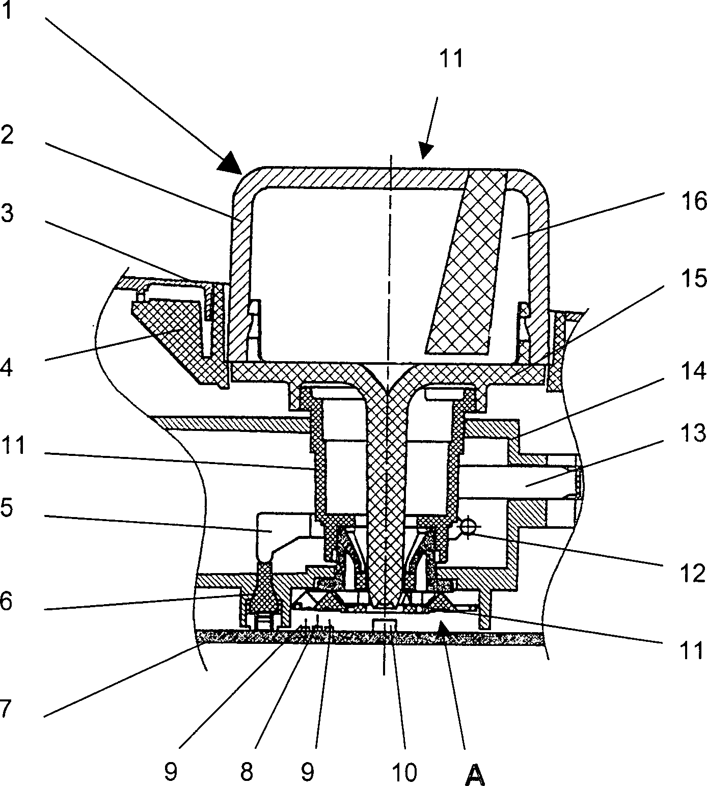
– für die Ausleuchtung und der radial um den Drehknopf (2) angeordneten Symbolik eine LED (Lichtquelle) (10) zentral in der Mitte angeordnet ist,
– dabei das Licht der Lichtquelle (10) über einen Lichtrotor (15) nach vorne zu der Knopfoberfläche und zu der Symbolik um den Knopf (2) geleitet wird,
– eine zweite Lichtquelle (8), die dezentral plaziert ist, die konstante Sendeinformation für den Inkrementgeber (1) und
– eine damit verbundene Lichtführung (11) bzw. Lochmaske (17) bei Bewegung bzw. Drehbewegung des Knopfes (2) ein veränderbares Helligkeitsmuster an die zwei Empfänger (9) abgibt, wobei
– ein seitlich vom Inkrementgeber (1) angeordnetes Schaltelement (7) über einen ringförmigen Hebel (5) betätigt wird, durch welchen beim axialen Betätigen des Knopfes...An optical incremental with push button, comprising a button, and at least one light-emitting transmitter and at least two receivers receiving the light and a coding which includes the control information of the incremental encoder, wherein
An LED (light source) (10) is arranged centrally in the center for the illumination and the symbolism arranged radially around the rotary knob (2),
- The light of the light source (10) via a light rotor (15) is forwarded to the button surface and to the symbolism around the button (2),
A second light source (8) placed in a decentralized manner, the constant transmission information for the incremental encoder (1) and
- An associated light guide (11) or shadow mask (17) upon movement or rotational movement of the knob (2) emits a variable brightness pattern to the two receivers (9), wherein
- A side of the incremental encoder (1) arranged switching element (7) via an annular lever (5) is actuated, by which the axial actuation of the button ...
Description
Einen
gattungsgemäßen optischen
Inkrementgeber offenbart die
Ein
optischer Drehschalter zur Kopplung von optischen Lichtleitfasern
wird in der
Aus
der
In
der
In
der
In
Die Erfindung stellt sich die Aufgabe, einen Drehsteller oder Inkrementgeber aufzuzeigen, dessen Bewegungs- und Richtungsinformationen über einen optischen Encoder dargestellt werden. Dabei liegt der Aufgabe das Problem zugrunde, dass ein zentrisches Ausleuchten und ein axiales Schalten ermöglicht sein soll.The Invention sets itself the task of a turntable or incremental encoder show its movement and direction information about a optical encoder are displayed. The task is the Problem underlying that a centric illumination and an axial Switching enabled should be.
Gelöst wird die Aufgabe durch die Merkmale des Patentanspruchs 1.Is solved the object by the features of claim 1.
Der Erfindung liegt die Idee zugrunde, für die Ausleuchtung und der radial um den Drehknopf angeordneten Symbolik eine LED (Lichtquelle) zentral in der Mitte anzuordnen und dabei das Licht der Lichtquelle über einen Lichtrotor nach vorne zu der Knopfoberfläche und zu der Symbolik um den Knopf zu leiten. Eine zweite Lichtquelle, die beispielsweise dezentral plaziert wird, gibt eine konstante Sendeinformation für den Inkrementgeber ab. Eine damit verbundene Lichtführung gibt bei Bewegung bzw. Drehbewegung des Knopfes ein veränderbares Helligkeitsmuster an zwei Empfänger ab. Beim Drehen wird so ein digitales Bitmuster (z. B. Graycode) erzeugt, welches über eine nachfolgende Elektronik weiterverarbeitet wird. In einer Ausführung können Sender und Empfänger in einer Ebene liegen und in direkte Nähe zueinander auf einer Leiterplatte befestigt sein. In einer weiteren Ausführung liegen sich Sender und Empfänger gegenüber.Of the Invention is based on the idea for the illumination and the radially arranged around the knob symbolism an LED (light source) central in the middle and thereby the light of the light source over a Light rotor forward to the button surface and to the symbolism to guide the button. A second light source, for example, decentralized is placed, gives a constant transmission information for the incremental encoder from. An associated light guide gives a changeable movement or rotary movement of the button Brightness pattern on two receivers from. When turning a digital bit pattern (eg Graycode) generated, which over a subsequent electronics is further processed. In one embodiment, transmitters and receiver lying in a plane and in close proximity to each other on a circuit board be attached. In a further embodiment are transmitter and receiver across from.
Mit der gleichen Anordnung lassen sich durch weiter Empfänger noch andere Schaltaufgaben realisieren.With the same arrangement can still be through other receivers realize other switching tasks.
Ein seitlich vom Drehsteller angeordnetes Schaltelement wird über einen ringförmigen Hebel betätigt. Durch ein axiales Betätigen des Knopfes wird dabei das Schaltelement betätigt und ein Kontakt auf der Leiterplatte geschlossen/geöffnet. Durch eine Änderung der Hebelübersetzung kann die Schaltcharakteristik (Schaltweg, Schaltkraft) leicht verschiedenen Bedürfnissen angepasst werden.One laterally arranged by the turntable switching element is connected via a annular Lever operated. By an axial actuation the button while the switching element is actuated and a contact on the PCB closed / opened. By a change the leverage ratio The switching characteristics (shift travel, shift force) can be slightly different needs be adjusted.
Anhand eines Ausführungsbeispiels mit Zeichnung soll die Erfindung näher erläutert werden.Based an embodiment with drawing, the invention will be explained in more detail.
Es zeigtIt shows
Ein
in
Mit
Für eine Übertragung
der Druckbewegung des Knopfes
Die
Funktionsweise des Inkrementgebers
Durch Drehen der Knopfes
By turning the knob
Wird
eine Druckfunktion ausgeführt,
wird der Knopf
In
Claims (9)
Priority Applications (2)
| Application Number | Priority Date | Filing Date | Title |
|---|---|---|---|
| DE10342325A DE10342325B4 (en) | 2003-09-11 | 2003-09-11 | Optical incremental encoder with pushbutton |
| PCT/EP2004/009984 WO2005026664A1 (en) | 2003-09-11 | 2004-09-08 | Optical incremental encoder comprising a pushbutton |
Applications Claiming Priority (1)
| Application Number | Priority Date | Filing Date | Title |
|---|---|---|---|
| DE10342325A DE10342325B4 (en) | 2003-09-11 | 2003-09-11 | Optical incremental encoder with pushbutton |
Publications (2)
| Publication Number | Publication Date |
|---|---|
| DE10342325A1 DE10342325A1 (en) | 2005-04-07 |
| DE10342325B4 true DE10342325B4 (en) | 2009-10-08 |
Family
ID=34258645
Family Applications (1)
| Application Number | Title | Priority Date | Filing Date |
|---|---|---|---|
| DE10342325A Expired - Lifetime DE10342325B4 (en) | 2003-09-11 | 2003-09-11 | Optical incremental encoder with pushbutton |
Country Status (2)
| Country | Link |
|---|---|
| DE (1) | DE10342325B4 (en) |
| WO (1) | WO2005026664A1 (en) |
Cited By (1)
| Publication number | Priority date | Publication date | Assignee | Title |
|---|---|---|---|---|
| DE102016122585A1 (en) * | 2016-11-23 | 2018-05-24 | Preh Gmbh | Turntable with improved, optical rotary position detection |
Families Citing this family (9)
| Publication number | Priority date | Publication date | Assignee | Title |
|---|---|---|---|---|
| WO2005050846A1 (en) | 2003-11-20 | 2005-06-02 | Preh Gmbh | Control element |
| DE102005057025B4 (en) * | 2005-07-15 | 2008-09-25 | Preh Gmbh | Illuminated control element |
| DE102007018603B4 (en) * | 2007-04-18 | 2018-10-11 | HELLA GmbH & Co. KGaA | Electric switch |
| DE102009036318A1 (en) * | 2009-02-09 | 2010-08-12 | Elobau Gmbh & Co. Kg | Electric switch e.g. Hall-switch, for use on operating elements of e.g. harvester, has control unit directly actuated by solid body outside of switch and illuminated in different colors based on positions using LED |
| DE102009011513B3 (en) * | 2009-03-06 | 2010-09-09 | Preh Gmbh | Improved illumination of a sliding joystick |
| FR2957692B1 (en) * | 2010-03-17 | 2012-06-08 | Delphi Tech Inc | RETRO-LIGHT ROTARY SWITCH CONTROL DEVICE BY A LIGHT GUIDE |
| KR20130037401A (en) * | 2011-10-06 | 2013-04-16 | 현대모비스 주식회사 | Button structure of multimedia system |
| GB2524113B (en) * | 2014-03-14 | 2016-05-04 | Red Lion 49 Ltd | Rotary control device |
| DE102019101264A1 (en) | 2019-01-18 | 2020-07-23 | Eaton Intelligent Power Limited | Push button arrangement with identification of a switching state |
Citations (6)
| Publication number | Priority date | Publication date | Assignee | Title |
|---|---|---|---|---|
| DE3390476T1 (en) * | 1983-04-07 | 1985-05-15 | Alexander Michael Oak Park Mich. Mumzhiu | Optical rotary switch |
| DE3821004A1 (en) * | 1988-06-22 | 1989-12-28 | Thomson Brandt Gmbh | ROTATED ENCODER FOR DIGITAL IMPULSES AND METHOD OF USE THEREOF |
| DE19712294A1 (en) * | 1997-03-24 | 1998-10-01 | Preh Elektro Feinmechanik | Rotational resistance |
| DE19733049A1 (en) * | 1997-07-31 | 1999-02-04 | Bosch Gmbh Robert | Optical increment encoder |
| DE19947529A1 (en) * | 1998-10-29 | 2000-05-11 | Valeo Electronique Creteil | Incremental optical encoder has pushbutton mounted on front panel to enable it to move parallel to rotation axis to expose 2 optical forks |
| DE10314315A1 (en) * | 2003-03-29 | 2004-10-28 | Preh Gmbh | Operating part e.g. rotary knob, has light distributing part which functions as coded disc for triggering operating function when top part of knob is displaced |
Family Cites Families (5)
| Publication number | Priority date | Publication date | Assignee | Title |
|---|---|---|---|---|
| US5180050A (en) * | 1991-10-15 | 1993-01-19 | Delco Electronics Corporation | Pushbutton rotary switch |
| DE19717215A1 (en) * | 1997-04-24 | 1998-10-29 | Bosch Gmbh Robert | Optical increment encoder |
| DE19832678A1 (en) * | 1998-07-21 | 2000-02-10 | Mannesmann Vdo Ag | Circuit arrangement with a rotary encoder |
| DE19964131A1 (en) * | 1999-11-22 | 2001-06-21 | Preh Elektro Feinmechanik | Rotary knob with button function |
| DE10127211B4 (en) * | 2001-06-05 | 2006-10-19 | Siemens Ag | Illuminable control unit, in particular for motor vehicle air conditioning systems |
-
2003
- 2003-09-11 DE DE10342325A patent/DE10342325B4/en not_active Expired - Lifetime
-
2004
- 2004-09-08 WO PCT/EP2004/009984 patent/WO2005026664A1/en not_active Ceased
Patent Citations (6)
| Publication number | Priority date | Publication date | Assignee | Title |
|---|---|---|---|---|
| DE3390476T1 (en) * | 1983-04-07 | 1985-05-15 | Alexander Michael Oak Park Mich. Mumzhiu | Optical rotary switch |
| DE3821004A1 (en) * | 1988-06-22 | 1989-12-28 | Thomson Brandt Gmbh | ROTATED ENCODER FOR DIGITAL IMPULSES AND METHOD OF USE THEREOF |
| DE19712294A1 (en) * | 1997-03-24 | 1998-10-01 | Preh Elektro Feinmechanik | Rotational resistance |
| DE19733049A1 (en) * | 1997-07-31 | 1999-02-04 | Bosch Gmbh Robert | Optical increment encoder |
| DE19947529A1 (en) * | 1998-10-29 | 2000-05-11 | Valeo Electronique Creteil | Incremental optical encoder has pushbutton mounted on front panel to enable it to move parallel to rotation axis to expose 2 optical forks |
| DE10314315A1 (en) * | 2003-03-29 | 2004-10-28 | Preh Gmbh | Operating part e.g. rotary knob, has light distributing part which functions as coded disc for triggering operating function when top part of knob is displaced |
Non-Patent Citations (1)
| Title |
|---|
| DE 103 14 315 A1 (Anmeldetag 29.03.2003) |
Cited By (2)
| Publication number | Priority date | Publication date | Assignee | Title |
|---|---|---|---|---|
| DE102016122585A1 (en) * | 2016-11-23 | 2018-05-24 | Preh Gmbh | Turntable with improved, optical rotary position detection |
| DE102016122585B4 (en) * | 2016-11-23 | 2018-07-12 | Preh Gmbh | Turntable with improved, optical rotary position detection |
Also Published As
| Publication number | Publication date |
|---|---|
| DE10342325A1 (en) | 2005-04-07 |
| WO2005026664A1 (en) | 2005-03-24 |
Similar Documents
| Publication | Publication Date | Title |
|---|---|---|
| DE10342325B4 (en) | Optical incremental encoder with pushbutton | |
| DE4332748B4 (en) | Switch, preferably for motor vehicle | |
| DE19964131A1 (en) | Rotary knob with button function | |
| DE10341016A1 (en) | Operating element, in particular for a multimedia system of a motor vehicle | |
| DE60303637T2 (en) | Switch with illuminated button | |
| DE602004011862T2 (en) | Actuating device of a motor vehicle air conditioning system | |
| WO2005027168A1 (en) | Control element | |
| DE112010004640T5 (en) | Structure of an electric switch comprising a 5-way toogle mechanism and an illuminated, flexible layer | |
| WO2005050846A1 (en) | Control element | |
| EP0974843B2 (en) | Rotary encoder | |
| DE102004054178A1 (en) | turntable | |
| DE10314315B4 (en) | operating element | |
| DE10342334B4 (en) | operating element | |
| DE10113534B4 (en) | Link switch unit for an automatic gearbox | |
| DE10059793B4 (en) | Multifunction control device for a motor vehicle | |
| WO2006010513A1 (en) | Rotating actuator | |
| DE102004031309B4 (en) | Steering wheel with a control | |
| EP1740910B1 (en) | Rotating actuator | |
| EP1873596B1 (en) | Portable radio remote control transmitter with backlit pushbuttons | |
| EP0895360A2 (en) | Optical incremental encoder | |
| EP1476329B1 (en) | Steering device including contactless data transmission between steering wheel and basic part | |
| DE102004022847A1 (en) | operating element | |
| EP1146409B1 (en) | Control element | |
| EP0874224A2 (en) | Optical rotational incremental encoder | |
| DE102010017992B3 (en) | Illuminable control knob, has handle bearing translucent indicating dial on front side and designed as back open part, and torque-proof drum formed with light chambers in interior of open part, where drum axis coincides with rotation axis |
Legal Events
| Date | Code | Title | Description |
|---|---|---|---|
| 8110 | Request for examination paragraph 44 | ||
| 8364 | No opposition during term of opposition | ||
| R082 | Change of representative |
Representative=s name: LOHMANNS, BERNARD, DIPL.-PHYS., DE |
|
| R071 | Expiry of right |