Die vorliegende Erfindung betrifft ein Steuerungssystem für einen Verbrennungsmotor, das eine Verbrennungsbetriebsart zwischen einer Schichtladeverbrennungsbetriebsart und einer homogenen Verbrennungsbetriebsart in Übereinstimmung mit einem Verbrennungsbetriebsartänderungserfordernis während eines Betriebs des Verbrennungsmotors ändert.The present invention relates to a control system for an internal combustion engine that changes a combustion mode between a stratified charge combustion mode and a homogeneous combustion mode in accordance with a combustion mode change requirement during operation of the internal combustion engine.
Ein Verbrennungsmotor der Direkteinspritzbauart spritzt eine geringe Menge Kraftstoff während eines Verdichtungstakts zum Ausbilden eines geschichteten Luft/Kraftstoff-Gemisches in der Nähe einer Zündkerze unter einer geringen Last ein. Der Verbrennungsmotor führt eine Schichtladeverbrennung durch Verbrennen des geschichteten Luft/Kraftstoff-Gemisches durch, wobei sich der Kraftstoffverbrauch und die Abgasemission verringert. Unter einer schweren Last spritzt der Verbrennungsmotor eine erhöhte Menge Kraftstoff in einem Einlasstakt ein, um ein homogenes Luft/Kraftstoff-Gemisch auszubilden. Somit führt der Verbrennungsmotor eine homogene Verbrennung durch Verbrennen des homogenen Luft/Kraftstoff-Gemisches durch, wobei sich seine Abgabe erhöht. Der Verbrennungsmotor der Direkteinspritzbauart ermittelt eine angeforderte Verbrennungsbetriebsart gemäß der Last und dergleichen während des Betriebs und ändert eine Verbrennungsbetriebsart zwischen einer Schichtladeverbrennungsbetriebsart (SCC-Betriebsart) und einer homogenen Verbrennungsbetriebsart (HC-Betriebsart) in Übereinstimmung mit der angeforderten Verbrennungsbetriebsart.A direct-injection type internal combustion engine injects a small amount of fuel during a compression stroke to form a stratified air-fuel mixture in the vicinity of a spark plug under a light load. The internal combustion engine performs stratified charge combustion by burning the stratified air-fuel mixture, thereby reducing fuel consumption and exhaust emission. Under a heavy load, the internal combustion engine injects an increased amount of fuel in an intake stroke to form a homogeneous air / fuel mixture. Thus, the internal combustion engine performs homogeneous combustion by burning the homogeneous air-fuel mixture, thereby increasing its output. The direct injection type internal combustion engine determines a requested combustion mode according to the load and the like during operation, and changes a combustion mode between a stratified charge combustion mode (SCC mode) and a homogeneous combustion mode (HC mode) in accordance with the requested combustion mode.
Bei einer Steuerung zum Ändern der Verbrennungsbetriebsart, die beispielsweise in dem japanischen Patent JP 3 201 936 B2 offenbart ist, werden dann, wenn die angeforderte Verbrennungsbetriebsart geändert wird, Steuerungsparameter eines Luftsystems, eines Kraftstoffsystems und eines Zündungssystems auf Sollwerte beziehungsweise Zielwerte der angeforderten Verbrennungsbetriebsart geändert. Die Sollwerte werden mit einer Abbildung oder ähnlichem für jede Verbrennungsbetriebsart gesetzt. Zum Verbrennen des Luft/Kraftstoff-Gemisches in dem Zylinder in der SCC-Betriebsart muss das geschichtete Luft/Kraftstoff-Gemisch in der Nähe der Zündkerze in dem Zylinder ausgebildet werden. Zum Ausbilden des geschichteten Luft/Kraftstoff-Gemisches muss ein Wirbelstrom beziehungsweise ein Drallstrom oder ein Rotationsstrom erzeugt werden. Daher ist ein Luftstromregulationsventil (ein Drall- beziehungsweise Wirbelregulationsventil oder ein Rotationsregulationsventil), das an einem Einlassanschluss angeordnet ist, auf einen Zielöffnungsgrad für die SCC-Betriebsart zum Erzeugen des Wirbelstroms beziehungsweise des Drallstroms oder des Rotationsstroms gesetzt. Andererseits ist bei der HC-Betriebsart das Luftstromregulationsventil auf einen anderen Öffnungsgrad, der von dem Öffnungsgrad für die SCC-Betriebsart verschieden ist, gesetzt. Wenn die Verbrennungsbetriebsart von der SCC-Betriebsart zu der HC-Betriebsart geändert wird, wird der Öffnungsgrad des Luftstromregulationsventils von einem Öffnungsgrad, der die Schichtladeverbrennung ermöglicht, zu einem anderen Öffnungsgrad geändert, der die homogene Verbrennung ermöglicht. Unterdessen werden andere Steuerungsparameter des Luftsystems, wie zum Beispiel ein Öffnungsgrad eines Drosselventils und eines Abgasrückführventils (EGR-Ventil) auf Zielwerte für die HC-Betriebsart geändert.In a control for changing the combustion mode, for example, in Japanese Patent JP 3 201 936 B2 is disclosed, when the requested combustion mode is changed, control parameters of an air system, a fuel system and an ignition system are changed to target values of the requested combustion mode. The set values are set with a map or the like for each combustion mode. For burning the air-fuel mixture in the cylinder in the SCC mode, the stratified air-fuel mixture needs to be formed in the vicinity of the spark plug in the cylinder. To form the stratified air / fuel mixture, an eddy current or a rotating current must be generated. Therefore, an airflow regulation valve (a swirl regulation valve or a rotation regulation valve) disposed at an intake port is set to an SCC mode target opening degree for generating the swirling flow or the rotating flow. On the other hand, in the HC mode, the airflow regulation valve is set to another opening degree other than the opening degree for the SCC mode. When the combustion mode is changed from the SCC mode to the HC mode, the opening degree of the airflow regulation valve is changed from an opening degree that enables the stratified charge combustion to another opening degree that enables the homogeneous combustion. Meanwhile, other control parameters of the air system, such as an opening degree of a throttle valve and an exhaust gas recirculation valve (EGR valve), are changed to target values for the HC mode.
Jedoch gibt es eine Ansprechverzögerung zwischen der Zeit, wenn die Steuerungsparameter des Luftsystems zu den Zielwerten der HC-Betriebsart geändert werden, und der Zeit, wenn ein Zustand des Luft/Kraftstoff-Gemisches in dem Zylinder tatsächlich einen homogenen Verbrennungsbereich von einem Schichtladeverbrennungsbereich erreicht. Der Schichtladeverbrennungsbereich (SCC-Bereich), der in 9 gezeigt ist, ist ein Bereich des Zustands des Luft/Kraftstoff-Gemisches, in dem die Schichtladeverbrennung durchgeführt werden kann. Der homogene Verbrennungsbereich (HC-Bereich), der in 9 gezeigt ist, ist ein Bereich des Zustands des Luft/Kraftstoff-Gemisches, in dem die homogene Verbrennung durchgeführt werden kann. Daher muss die Schichtladeverbrennung während der Ansprechverzögerungsdauer fortgesetzt werden. Wenn jedoch der Steuerungsparameter des Luftstromregulationsventils zu dem Zielwert der HC-Betriebsart gemeinsam mit den anderen Steuerungsparametern des Luftsystems geändert wird, kann der Wirbelstrom beziehungsweise der Drallstrom oder der Rotationsstrom, der für die Schichtladeverbrennung geeignet ist, in dem Zylinder nicht vor dem Zustand erzeugt werden, wenn das Luft/Kraftstoff-Gemisch tatsächlich den HC-Bereich erreicht. Demgemäß kann das geschichtete Luft/Kraftstoff-Gemisch nicht in der Nähe der Zündkerze in dem Zylinder ausgebildet werden. Als Folge wird ein Verbrennungszustand unstabil und kann eine Drehmomentschwankung oder eine Fehlzündung auftreten.However, there is a response delay between the time when the control parameters of the air system are changed to the target values of the HC mode and the time when a state of the air / fuel mixture in the cylinder actually reaches a homogeneous combustion range from a stratified charge combustion region. The stratified charge combustion area (SCC area), which in 9 is a range of the state of the air-fuel mixture in which the stratified charge combustion can be performed. The homogeneous combustion range (HC range), which in 9 is shown, is a range of the state of the air / fuel mixture in which the homogeneous combustion can be performed. Therefore, the stratified charge combustion must be continued during the response delay period. However, when the control parameter of the airflow regulation valve is changed to the target value of the HC mode together with the other control parameters of the air system, the eddy current or the rotary current suitable for the stratified charge combustion can not be generated in the cylinder before the state, when the air / fuel mixture actually reaches the HC range. Accordingly, the stratified air / fuel mixture can not be formed in the vicinity of the spark plug in the cylinder. As a result, a combustion state becomes unstable, and torque fluctuation or misfire may occur.
Ferner ist aus der EP 0 884 461 A2 ein Steuerungssystem für einen Verbrennungsmotor gemäß dem Oberbegriff von Anspruch 1 bekannt. Ein weiteres Steuerungssystem für einen Verbrennungsmotor ist in der JP 2002-070 613 A offenbart.Furthermore, from the EP 0 884 461 A2 a control system for an internal combustion engine according to the preamble of claim 1 is known. Another control system for an internal combustion engine is in the JP 2002-070613A disclosed.
Es ist daher die Aufgabe der vorliegenden Erfindung, ein Steuerungssystem für einen Verbrennungsmotor zu schaffen, das in der Lage ist, eine Verbrennungsbetriebsart unter Beibehalten eines stabilen Verbrennungszustands zu ändern. It is therefore the object of the present invention to provide a control system for an internal combustion engine capable of changing a combustion mode while maintaining a stable combustion state.
Erfindungsgemäß wird diese Aufgabe mit einem Steuerungssystem für einen Verbrennungsmotor mit den Merkmalen von Anspruch 1 gelöst.According to the invention this object is achieved with a control system for an internal combustion engine having the features of claim 1.
Das erfindungsgemäße Steuerungssystem hat eine Luftstromregulationseinrichtung und eine Verbrennungsbetriebsartänderungseinrichtung. Die Verbrennungsbetriebsartänderungseinrichtung ändert Steuerungsparameter der Luftstromregulationseinrichtung, eines Luftsystems, das ein anderes als die Luftstromregulationseinrichtung ist, eines Kraftstoffsystems und eines Zündungssystems, wenn eine Verbrennungsbetriebsart geändert wird. Wenn die Verbrennungsbetriebsart von der SCC-Betriebsart zu der HC-Betriebsart geändert wird, wird der Steuerungsparameter der Luftstromregulationseinrichtung bei einer verzögerten Zeitabstimmung im Vergleich mit der Zeitabstimmung zum Ändern der anderen Steuerungsparameter des Luftsystems geändert.The control system according to the invention has an air flow regulation device and a combustion mode change device. The combustion mode changing means changes control parameters of the air flow regulating means, an air system other than the air flow regulating means, a fuel system, and an ignition system when a combustion mode is changed. When the combustion mode is changed from the SCC mode to the HC mode, the control parameter of the air flow controller is changed at a delayed timing as compared with the timing for changing the other control parameters of the air system.
Somit wird auch nachdem die angeforderte Verbrennungsbetriebsart zu der HC-Betriebsart geändert wird, der Steuerungsparameter der Luftstromsteuerungseinrichtung auf einem Zielwert der SCC-Betriebsart für eine bestimmte Zeitdauer beibehalten. Als Folge kann auch nachdem die angeforderte Verbrennungsbetriebsart zu der HC-Betriebsart geändert ist, eine stabile Schichtladeverbrennung für eine bestimmte Zeitdauer durch Erzeugen eines Luftstroms in dem Zylinder (wie zum Beispiel ein Wirbelstrom beziehungsweise ein Drallstrom oder ein Rotationsstrom) fortgesetzt werden, der für die Schichtladeverbrennung geeignet ist.Thus, even after the requested combustion mode is changed to the HC mode, the control parameter of the airflow control device is maintained at a target value of the SCC mode for a certain period of time. As a result, even after the requested combustion mode is changed to the HC mode, stable stratified charge combustion for a certain period of time can be continued by generating an air flow in the cylinder (such as an eddy current or a rotational flow) necessary for stratified charge combustion suitable is.
Der Steuerungsparameter der Luftstromsteuerungseinrichtung wird zu dem Zielwert der HC-Betriebsart geändert, nachdem das Luft/Kraftstoff-Gemisch in dem Zylinder einen Zustand erreicht, in dem die homogene Verbrennung durchgeführt werden kann. Somit wird die Verbrennungsbetriebsart von der SCC-Betriebsart zu der HC-Betriebsart unter Beibehalten eines stabilen Verbrennungszustands geändert. Als Folge wird eine Drehmomentschwankung oder eine Fehlzündung auch dann verhindert, wenn die Verbrennungsbetriebsart geändert wird.The control parameter of the airflow control device is changed to the target value of the HC mode after the air-fuel mixture in the cylinder reaches a state where the homogeneous combustion can be performed. Thus, the combustion mode is changed from the SCC mode to the HC mode while maintaining a stable combustion state. As a result, torque fluctuation or misfire is prevented even when the combustion mode is changed.
Merkmale und Vorteile eines Ausführungsbeispiels werden ebenso wie Verfahren des Betriebs und die Funktion der zugehörigen Teile aus einem Studium der folgenden genauen Beschreibung, den beigefügten Ansprüchen und den Zeichnungen erkennbar, die alle einen Teil dieser Anmeldung bilden.Features and advantages of an embodiment as well as methods of operation and the function of the related parts will become apparent from a study of the following detailed description, the appended claims and the drawings, all of which form a part of this application.
1 ist ein schematisches Diagramm, das ein Verbrennungsmotorsteuerungssystem gemäß einem Ausführungsbeispiel der vorliegenden Erfindung zeigt; 1 Fig. 10 is a schematic diagram showing an engine control system according to an embodiment of the present invention;
2 ist ein Ablaufdiagramm, das einen Prozessablauf einer Verbrennungsmotorsteuerungshauptroutine gemäß dem Ausführungsbeispiel zeigt; 2 FIG. 10 is a flowchart showing a process flow of an engine control main routine according to the embodiment; FIG.
3 ist ein Ablaufdiagramm, das einen Prozessablauf einer Verbrennungsbetriebsartermittelungsroutine gemäß dem Ausführungsbeispiel zeigt; 3 FIG. 10 is a flowchart showing a process flow of a combustion operation average routine according to the embodiment; FIG.
4 ist ein Ablaufdiagramm, das einen Prozessablauf einer Verbrennungsbetriebsartänderungssteuerungsroutine gemäß dem Ausführungsbeispiel zeigt; 4 FIG. 10 is a flowchart showing a process flow of a combustion mode change control routine according to the embodiment; FIG.
5 ist ein Ablaufdiagramm, das einen Prozessablauf einer Luftsystemsteuerungsroutine gemäß dem Ausführungsbeispiel zeigt; 5 FIG. 10 is a flowchart showing a process flow of an air-system control routine according to the embodiment; FIG.
6 ist ein Ablaufdiagramm, das einen Prozessablauf einer Luftstromregulationsventilsteuerungsroutine gemäß dem Ausführungsbeispiel zeigt; 6 FIG. 10 is a flowchart showing a process flow of an airflow regulation valve control routine according to the embodiment; FIG.
7 ist ein Ablaufdiagramm, das einen Prozessablauf einer Kraftstoffsystemsteuerungsroutine gemäß dem Ausführungsbeispiel zeigt; 7 FIG. 10 is a flowchart showing a process flow of a fuel system control routine according to the embodiment; FIG.
8 ist ein Ablaufdiagramm, das einen Prozessablauf einer Zündungssystemsteuerungsroutine gemäß dem Ausführungsbeispiel zeigt; 8th FIG. 10 is a flowchart showing a process flow of an ignition system control routine according to the embodiment; FIG.
9 ist eine Grafik, die eine Beziehung zwischen einer Intensität einer Luftströmung und eines Luft/Kraftstoff-Verhältnis-Bereichs zeigt, bei dem die Schichtladeverbrennung oder die homogene Verbrennung durchgeführt werden kann; 9 Fig. 12 is a graph showing a relationship between an intensity of air flow and an air-fuel ratio range at which stratified charge combustion or homogeneous combustion can be performed;
10 ist eine Grafik, die eine Beziehung zwischen der Luftströmungsintensität und einem stabilen Verbrennungsbereich der Schichtladeverbrennung oder der homogenen Verbrennung zeigt; 10 Fig. 12 is a graph showing a relationship between the air flow intensity and a stable combustion region of stratified charge combustion or homogeneous combustion;
11 ist ein Zeitdiagramm, das einen Verbrennungsbetriebsartänderungsbetrieb eines herkömmlichen Verbrennungsmotors der Direkteinspritzbauart zeigt; und 11 FIG. 10 is a time chart showing a combustion mode changing operation of a conventional direct injection type internal combustion engine; FIG. and
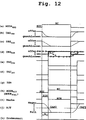
12 ist ein Zeitdiagramm, das einen Verbrennungsbetriebsartänderungsbetrieb gemäß dem Ausführungsbeispiel zeigt. 12 FIG. 14 is a timing chart showing a combustion mode change operation according to the embodiment. FIG.
Unter Bezugnahme auf 1 ist eine Brennkraftmaschine 11 der Direkteinspritzbauart dargestellt. Ein Luftreiniger beziehungsweise ein Luftfilter 13 ist an dem stromaufwärtigsten Ende eines Einlassrohrs 12 des Verbrennungsmotors 11 angeordnet. Ein Drosselventil 15 ist stromabwärts von dem Luftreiniger 13 angeordnet. Ein Öffnungsgrad des Drosselventils 15 (ein Drosselventilöffnungsgrad) wird durch einen Motor 14 gesteuert, der auf der Grundlage eines Ausgabesignals von der elektronischen Verbrennungsmotorsteuerungseinheit (ECU) 16 angetrieben wird. Somit wird der Drosselventilöffnungsgrad und eine Einlassluftmenge, die in jeweilige Zylinder des Verbrennungsmotors 11 gezogen wird, reguliert. Ein Drosselsensor 17 ist in der Nähe des Drosselventils 15 zum Messen des Drosselventilöffnungsgrades angeordnet.With reference to 1 is an internal combustion engine 11 the direct injection type shown. An air cleaner or an air filter 13 is at the most upstream end of an inlet pipe 12 of the internal combustion engine 11 arranged. A throttle valve 15 is downstream of the air purifier 13 arranged. An opening degree of the throttle valve 15 (a throttle valve opening degree) is controlled by a motor 14 controlled on the basis of an output signal from the electronic engine control unit (ECU) 16 is driven. Thus, the throttle valve opening degree and an intake air amount flowing into respective cylinders of the internal combustion engine become 11 pulled, regulated. A throttle sensor 17 is near the throttle valve 15 arranged to measure the throttle valve opening degree.
Ein Ausgleichsbehälter 19 ist stromabwärts von dem Drosselventil 15 angeordnet. Einlasskrümmer 20 sind mit dem Ausgleichsbehälter 15 zum Einführen der Luft in die jeweiligen Zylinder des Verbrennungsmotors 11 verbunden. Jeder Einlasskrümmer 20 ist mit einem ersten Einlassdurchgang 21 und einem zweiten Einlassdurchgang 22 getrennt ausgebildet. Jeder Zylinder des Verbrennungsmotors 11 ist mit zwei Einlassanschlüssen 23 ausgebildet. Der erste Einlassdurchgang 21 ist mit einem von den Einlassanschlüssen 23 verbunden und der zweite Einlassanschluss 22 ist mit dem anderen verbunden.A surge tank 19 is downstream of the throttle valve 15 arranged. intake manifold 20 are with the expansion tank 15 for introducing the air into the respective cylinders of the internal combustion engine 11 connected. Each intake manifold 20 is with a first intake passage 21 and a second inlet passage 22 trained separately. Every cylinder of the internal combustion engine 11 is with two inlet connections 23 educated. The first intake passage 21 is with one of the inlet ports 23 connected and the second inlet port 22 is connected to the other.
Ein Luftstromregulationsventil (ASR-Ventil) 24 ist in jedem von den zweiten Einlassdurchgängen zum Erzeugen eines Zirkulationsstroms (eines Wirbelstroms beziehungsweise eines Drallstroms oder eines Rotationsstroms) eines Luft/Kraftstoff-Gemisches während eines Betriebs einer Schichtladeverbrennungsbetriebsart (SCC-Betriebsart) angeordnet. Die ASR-Ventile 24 der jeweiligen Zylinder sind mit einem Schrittmotor 26 über eine gemeinsame Welle 25 verbunden. Der Schrittmotor 26 wird auf der Grundlage eines Ausgabesignals von der ECU 16 angetrieben, um den Öffnungsgrad der ASR-Ventile 24 und die Intensität der Luftströme zu regulieren, die in den jeweiligen Zylindern strömen. Ein Luftstromregulationsventilsensor 27 ist an dem Schrittmotor 26 zum Erfassen des Öffnungsgrads der ASR-Ventile 24 angebracht.An airflow regulation valve (ASR valve) 24 is disposed in each of the second intake passages for generating a circulation flow (an eddy current or a rotational flow) of an air-fuel mixture during an operation of a stratified charge combustion mode (SCC mode). The ASR valves 24 The respective cylinders are equipped with a stepper motor 26 about a common wave 25 connected. The stepper motor 26 is based on an output signal from the ECU 16 driven to the degree of opening of the ASR valves 24 and to regulate the intensity of the airflows flowing in the respective cylinders. An airflow regulation valve sensor 27 is at the stepper motor 26 for detecting the opening degree of the ASR valves 24 appropriate.
Ein Kraftstoffeinspritzventil 28 ist an dem oberen Teil jedes Zylinders des Verbrennungsmotors 11 zum direkten Einspritzen von Kraftstoff in den Zylinder angeordnet. Der Kraftstoff, der von einem Kraftstofftank zu einem Kraftstoffförderrohr 30 durch ein Kraftstoffrohr 29 geführt wird, wird direkt von dem Kraftstoffeinspritzventil 28 in den Zylinder eingespritzt und wird mit der Luft gemischt, die durch den Einlassanschluss 23 eingeführt wird. Somit wird das Luft/Kraftstoff-Gemisch in dem Zylinder ausgebildet. Eine Zündkerze ist an einem Zylinderkopf jedes Zylinders angeordnet. Das Luft/Kraftstoff-Gemisch in dem Zylinder wird durch eine Funkenentladung durch die Zündkerze gezündet. Ein Zylinderermittelungssensor 32 erzeugt einen Zylinderermittelungsabgabeimpuls, wenn ein Kolben eines spezifischen Zylinders (beispielsweise ein erster Zylinder) einen oberen Totpunkt (TDC) des Zylinders bei einem Einlasstakt erreicht. Ein Kurbelwinkelsensor 33 erzeugt einen Kurbelwinkelausgangsimpuls jedes Mal dann, wenn eine Kurbelwelle des Verbrennungsmotors 11 sich um einen vorbestimmen Kurbelwinkel (CA) dreht (beispielsweise 30° CA beziehungsweise KW). Eine Messung des Kurbelwinkels und der Verbrennungsmotordrehzahl und die Zylinderermittelung zum Spezifizieren der Kurbelwinkelposition des Zylinders werden auf der Grundlage der vorstehend genannten Ausgabeimpulse durchgeführt.A fuel injector 28 is at the upper part of each cylinder of the internal combustion engine 11 arranged for direct injection of fuel into the cylinder. The fuel going from a fuel tank to a fuel delivery pipe 30 through a fuel pipe 29 is guided, directly from the fuel injector 28 injected into the cylinder and is mixed with the air passing through the inlet port 23 is introduced. Thus, the air / fuel mixture is formed in the cylinder. A spark plug is disposed on a cylinder head of each cylinder. The air / fuel mixture in the cylinder is ignited by a spark discharge through the spark plug. A cylinder detection sensor 32 generates a cylinder average output pulse when a piston of a specific cylinder (for example, a first cylinder) reaches a top dead center (TDC) of the cylinder at an intake stroke. A crank angle sensor 33 generates a crank angle output pulse every time a crankshaft of the internal combustion engine 11 is about a predetermined crank angle (CA) rotates (for example, 30 ° CA or KW). A measurement of the crank angle and the engine speed and the cylinder average for specifying the crank angle position of the cylinder are performed on the basis of the aforementioned output pulses.
Ein Abgas wird aus jeweiligen Auslassanschlüssen beziehungsweise Abgasanschlüssen 34, die an den jeweiligen Zylindern ausgebildet sind, zu einem Auslassrohr beziehungsweise Abgasrohr 37 durch einen Auslasskrümmer beziehungsweise Abgaskrümmer 36 ausgestoßen und wird bei dem Abgasrohr beziehungsweise Auslassrohr 37 zusammengeführt. Ein Drei-Wege-Katalysator 38 und ein Katalysator 39 der Stickoxidabsorptions-Reduktionsbauart (ein NOx-Katalysator) sind an dem Abgasrohr 37 in Reihe angeordnet. Der Drei-Wege-Katalysator 38 und der NOx-Katalysator 39 reinigen das Abgas bei einem Luft/Kraftstoff-Verhältnis um ein stöchiometrisches Luft/Kraftstoff-Verhältnis. Der NOx-Katalysator 39 absorbiert Stickoxid, das in dem Abgas während des SCC-Betriebsartbetriebs enthalten ist (magere Verbrennungsbetriebsart), bei der die Konzentration von Sauerstoff in dem Abgas hoch ist. Das absorbierte Stickstoffoxid wird durch den NOx-Katalysator 39 reduziert und gereinigt und wird ausgestoßen, wenn die Verbrennungsbetriebsart zu einer homogenen Verbrennungsbetriebsart (HC-Betriebsart) geändert wird. Wenn die Verbrennungsbetriebsart zu der HC-Betriebsart geändert wird, wird das Luft/Kraftstoff-Verhältnis zu einem fetten Luft/Kraftstoff-Verhältnis (ein niedriges Luft/Kraftstoff-Verhältnis) oder zu einem Verhältnis um das stöchiometrische Luft/Kraftstoff-Verhältnis geändert und wird die Konzentration des Sauerstoffs in dem Abgas verringert.An exhaust gas is from respective exhaust ports or exhaust ports 34 formed on the respective cylinders to an exhaust pipe or exhaust pipe 37 through an exhaust manifold or exhaust manifold 36 ejected and is at the exhaust pipe or outlet pipe 37 merged. A three-way catalyst 38 and a catalyst 39 The nitrogen oxide absorption reduction (NO x ) type catalytic converter is on the exhaust pipe 37 arranged in a row. The three-way catalyst 38 and the NO x catalyst 39 purify the exhaust gas at an air / fuel ratio by a stoichiometric air / fuel ratio. The NO x catalyst 39 absorbs nitrogen oxide that is in the exhaust gas during the SCC mode operation (lean combustion mode) in which the concentration of oxygen in the exhaust gas is high. The absorbed nitrogen oxide is through the NO x catalyst 39 is reduced and purified, and is discharged when the combustion mode is changed to a homogeneous combustion mode (HC mode). When the combustion mode is changed to the HC mode, the air-fuel ratio is changed to become a rich air-fuel ratio (a low air-fuel ratio) or a ratio around the stoichiometric air-fuel ratio reduces the concentration of oxygen in the exhaust gas.
Ein Stickstoffoxidsensor (ein NOx-Sensor) ist stromabwärts von dem NOx-Katalysator 39 zum Messen der Konzentration des Stickstoffoxids in dem Abgas angeordnet, das von dem NOx-Katalysator 39 ausgestoßen wird. Wenn eine Menge des Stickstoffoxids, das durch den NOx-Katalysator 39 absorbiert ist, einen vorbestimmten Wert übersteigt, wird die Verbrennungsbetriebsart von der SCC-Betriebsart zu der HC-Betriebsart zeitweilig geändert. Die Menge des absorbierten Stickstoffoxids wird aus der gemessenen Konzentration des Stickstoffoxids geschätzt, das in dem Abgas enthalten ist. Durch die Zeit, wenn die Verbrennungsbetriebsart von der SCC-Betriebsart zu der HC-Betriebsart geändert wird, wird das absorbierte Stickstoffoxid durch den NOx-Katalysator 39 reduziert und ausgestoßen. Somit wird das Stickstoffoxid abgeführt.A nitrogen oxide sensor (an NOx sensor) downstream of the NO x catalyst 39 for measuring the concentration of the nitrogen oxide in the exhaust gas, that of the NO x catalyst 39 is ejected. When an amount of the nitrogen oxide that passes through the NO x catalyst 39 is absorbed, exceeds a predetermined value, the combustion mode is temporarily changed from the SCC mode to the HC mode. The amount of absorbed nitrogen oxide is estimated from the measured concentration of the nitrogen oxide contained in the exhaust gas. By the time when the combustion mode is changed from the SCC mode to the HC mode, the absorbed nitrogen oxide becomes the NO x catalyst 39 reduced and expelled. Thus, the nitrogen oxide is removed.
Ein Abgasrückführrohr (EGR-Rohr) 40 ist mit einem Abschnitt des Abgasrohrs 37 an der stromaufwärtigen Seite des Drei-Wege-Katalysators 38 und mit dem Ausgleichsbehälter 19 verbunden. Das EGR-Rohr 40 führt einen Teil des Abgases zu dem Einlasssystem. Ein Abgasrückführventil (EGR-Ventil) 41 ist an dem EGR-Rohr 40 angeordnet. Ein Öffnungsgrad des EGR-Ventils (ein EGR-Ventilöffnungsgrad) wird auf der Grundlage eines Ausgabesignals von der ECU 16 reguliert. Eine Menge des Rückführgases (EGR-Menge) wird auf der Grundlage des EGR-Ventilöffnungsgrads reguliert. Ein Beschleunigersensor 42 ist an einem Beschleunigerpedal 18 zum Erfassen einer Beschleunigerposition (ACCP) angeordnet.An exhaust gas recirculation pipe (EGR pipe) 40 is with a section of the exhaust pipe 37 on the upstream side of the three-way catalyst 38 and with the expansion tank 19 connected. The EGR pipe 40 takes a part of the exhaust gas to the intake system. An exhaust gas recirculation valve (EGR valve) 41 is on the EGR pipe 40 arranged. An opening degree of the EGR valve (an EGR valve opening degree) is set on the basis of an output signal from the ECU 16 regulated. An amount of the recirculation gas (EGR amount) is regulated based on the EGR valve opening degree. An accelerator sensor 42 is on an accelerator pedal 18 arranged to detect an accelerator position (ACCP).
Die Ausgabesignale von verschiedenen Sensoren werden der ECU 16 eingegeben. Die ECU 16 weist hauptsächlich einen Mikrocomputer auf. Die ECU 16 führt Routinen, die in den 2 bis 8 gezeigt sind, aus, die in dem ROM gespeichert sind, der in der ECU 16 enthalten ist. Somit ändert die ECU 16 die Verbrennungsbetriebsart zwischen der SCC-Betriebsart und der HC-Betriebsart in Übereinstimmung mit einer Anforderung zum Ändern der Verbrennungsbetriebsart.The output signals from various sensors become the ECU 16 entered. The ECU 16 mainly has a microcomputer. The ECU 16 performs routines in the 2 to 8th are stored in the ROM stored in the ECU 16 is included. Thus, the ECU changes 16 the combustion mode between the SCC mode and the HC mode in accordance with a request to change the combustion mode.
In der SCC-Betriebsart wird ein Steuerungsparameter oder ein Öffnungsgrad des ASR-Ventils 24 auf einen Zielwert für die Schichtladeverbrennung gesetzt (beispielsweise 50%), um einen Zirkulationsstrom, wie zum Beispiel einen Wirbelstrom beziehungsweise einen Drallstrom beziehungsweise eine Verwirbelung oder einen Rotationsstrom in dem Zylinder zu erzeugen. Unterdessen wird eine geringe Menge Kraftstoff während eines Verdichtungstakts eingespritzt. Somit wird ein mageres geschichtetes Luft/Kraftstoff-Gemisch in dem Zylinder ausgebildet. Das magere geschichtete Luft/Kraftstoff-Gemisch weist eine relativ konzentrierte Schicht in der Nähe der Zündkerze auf. Ein Betrieb mit einem niedrigen Kraftstoffverbrauch und einer niedrigen Abgasemission wird durch Verbrennen des mageren geschichteten Luft/Kraftstoff-Gemisches erzielt.In SCC mode, a control parameter or opening degree of the ASR valve becomes 24 set to a target value for the stratified charge combustion (for example, 50%) to generate a circulation flow such as an eddy current or a swirling flow or a rotating flow in the cylinder. Meanwhile, a small amount of fuel is injected during a compression stroke. Thus, a lean stratified air / fuel mixture is formed in the cylinder. The lean stratified air / fuel mixture has a relatively concentrated layer near the spark plug. Operation with low fuel consumption and low exhaust emission is achieved by burning the lean stratified air / fuel mixture.
In der HC-Betriebsart wird der Steuerungsparameter des ASR-Ventils 24 auf einen Zielwert der HC-Betriebsart, beispielsweise 0% gesetzt (vollständig geschlossene Position) bei einer geringen Last oder auf 100% (vollständig geöffnete Position) unter einer schweren Last. Unterdessen wird die Kraftstoffeinspritzmenge erhöht, so dass das Luft/Kraftstoff-Verhältnis ein Verhältnis um das stöchiometrische Luft/Kraftstoff-Verhältnis oder ein Verhältnis wird, das geringfügig fetter (geringer) als das stöchiometrische Luft/Kraftstoff-Verhältnis ist. Der Kraftstoff wird während eines Einlasstakts zum Ausbilden eines homogenen Luft/Kraftstoff-Verhältnisses eingespritzt. Somit wird eine Verbrennungsmotorabgabe durch Verbrennen des homogenen Luft/Kraftstoff-Gemisches erhöht.In HC mode, the control parameter of the ASR valve 24 to a target value of the HC mode, for example, 0% set (fully closed position) at a low load or 100% (fully opened position) under a heavy load. Meanwhile, the fuel injection amount is increased so that the air-fuel ratio becomes a ratio around the stoichiometric air-fuel ratio or a ratio that is slightly fatter (less) than the stoichiometric air-fuel ratio. The fuel is injected during an intake stroke to form a homogeneous air / fuel ratio. Thus, an engine output is increased by burning the homogeneous air / fuel mixture.
Wenn für diesen Fall die angeforderte Verbrennungsbetriebsart MODEREQ von der SCC-Betriebsart zu der HC-Betriebsart geändert wird, wie in 12(a) gezeigt ist, ändert die ECU 16 Steuerungsparameter des Luftsystems außer des ASR-Ventils 24 auf Zielwerte der HC-Betriebsart. Genauer gesagt ändert die ECU 16 den Drosselventilöffnungsgrad DEGTHR und den EGR-Ventilöffnungsgrad DEGEGR auf Zielwerte der HC-Betriebsart, wie in den 12(b) und 12(c) gezeigt ist. Unterdessen ändert die ECU 16 das Ziel-Luft/Kraftstoff-Verhältnis A/F auf den Zielwert der HC-Betriebsart, wie in 12(j) gezeigt ist. In 12 stellen durchgezogene Linien Zielwerte dar und stellen gestrichelte Linien tatsächliche Werte dar. Wenn darauf das Luft/Kraftstoff-Gemisch in dem Zylinder einen Zustand erreicht, in dem die homogene Verbrennung durchgeführt werden kann, ändert die ECU 16 den Öffnungsgrad des ASR-Ventils 24 (ASR-Ventilöffnungsgrad (DEGASR) auf eine vollständig geöffnete Position, welche der Zielwert der HC-Betriebsart ist. Wenn andererseits die angeforderte Verbrennungsbetriebsart MODEREQ von der HC-Betriebsart zu der SCC-Betriebsart geändert wird, ändert die ECU 16 unmittelbar den Drosselventilöffnungsgrad DEGTHR, den EGR-Ventilöffnungsgrad DEGEGR, den ASR-Ventilöffnungsgrad DEGASR und das Ziel-Luft/Kraftstoff-Verhältnis A/F auf die Zielwerte der SCC-Betriebsart zur gleichen Zeit, wie in 12 gezeigt ist.In this case, when the requested combustion mode MODE REQ is changed from the SCC mode to the HC mode, as in FIG 12 (a) shown changes the ECU 16 Control parameters of the air system other than the ASR valve 24 on target values of HC mode. Specifically, the ECU changes 16 the throttle valve opening degree DEG THR and the EGR valve opening degree DEG EGR to target values of the HC mode, as in 12 (b) and 12 (c) is shown. Meanwhile, the ECU changes 16 the target air / fuel ratio A / F to the target value of the HC mode, as in 12 (j) is shown. In 12 Solid lines represent target values and dashed lines represent actual values. If thereupon, the air / fuel mixture in the cylinder reaches a state where homogeneous combustion can be performed, the ECU changes 16 the degree of opening of the ASR valve 24 (ASR valve opening degree (DEG ASR ) to a fully open position which is the target value of the HC mode, on the other hand, when the requested combustion mode MODE REQ is changed from the HC mode to the SCC mode, changes the ECU 16 directly the throttle valve opening degree DEG THR , the EGR valve opening degree DEG EGR , the ASR valve opening degree DEG ASR and the target air-fuel ratio A / F to the target values of the SCC mode at the same time as in 12 is shown.
Wenn des weiteren das Luft/Kraftstoff-Gemisch in dem Zylinder einen Zustand erreicht, in dem die angeforderte Verbrennungsbetriebsart durchgeführt werden kann, ändert die ECU 16 Steuerungsparameter eines Kraftstoffsystems und eines Zündungssystems auf Zielwerte der angeforderten Verbrennungsbetriebsart. Genauer gesagt ändert die ECU 16 eine Einspritzzeitabstimmung und eine Zündungszeitabstimmung IGN, wie in den 12(e), 12(f) und 12(g) gezeigt ist. Die ECU 16 ändert die Einspritzzeitabstimmung durch Ändern einer Kompressionstakteinspritzmenge INJCOM und einer Einlasstakteinspritzmenge INJINT, wie in den 12(e) und 12(f) gezeigt ist. Die Verdichtungstakteinspritzmenge INJCOM ist eine Menge des Kraftstoffs, der während des Verdichtungstakts eingespritzt wird. Die Einlasstakteinspritzmenge INJINT ist eine Menge des Kraftstoffs, der während des Einlasstakts eingespritzt wird.Further, when the air-fuel mixture in the cylinder reaches a state in which the requested combustion mode can be performed, the ECU changes 16 Control parameters of a fuel system and an ignition system to target values of the requested combustion mode. Specifically, the ECU changes 16 an injection timing and an ignition timing IGN, as in FIGS 12 (e) . 12 (f) and 12 (g) is shown. The ECU 16 changes the injection timing by changing a compression stroke injection amount INJ COM and an intake stroke injection amount INJ INT , as in FIGS 12 (e) and 12 (f) is shown. The compression stroke injection amount INJ COM is an amount of the fuel injected during the compression stroke. The intake stroke injection amount INJ INT is an amount of the fuel injected during the intake stroke.
Als nächstes werden Vorgangsinhalte von Routinen, die in den 2 bis 8 gezeigt sind, die durch die ECU 16 zum Durchführen der vorstehend genannten Steuerungen ausgeführt werden, erklärt.Next, process contents of routines that are in the 2 to 8th shown by the ECU 16 for performing the above-mentioned controls explained.
(Verbrennungsmotorsteuerungshauptroutine)(Internal combustion engine control main routine)
Eine in 2 gezeigte Verbrennungsmotorsteuerungshauptroutine (ECM-Routine) wird bei vorbestimmen Zeitintervallen durchgeführt, nachdem ein Zündschalter eingeschaltet ist. Wenn die ECM-Routine gestartet ist, wird ein angefordertes Drehmoment (TORQEREQ) auf der Grundlage der Beschleunigerposition ACCP, der Verbrennungsmotordrehzahl NE und dergleichen in Schritt 100 berechnet. Darauf schreitet der Prozess zu Schritt 200 weiter und eine Verbrennungsbetriebsartermittelungsroutine (CMD-Routine), die in 3 gezeigt ist, wird zum Ermitteln einer Verbrennungsbetriebsart durchgeführt. Darauf schreitet der Prozess zu Schritt 300 weiter und wird eine in 4 gezeigte Verbrennungsbetriebsartänderungssteuerungsroutine (CMCC-Routine) durchgeführt. Wenn es eine Anforderung zum Ändern der Verbrennungsbetriebsart gibt, wird eine Verbrennungsbetriebsartänderungssteuerung durchgeführt. Dann werden in den folgenden Schritten 400 bis 700 eine in 5 gezeigte Luftsystemsteuerungsroutine (ASC-Routine), eine in 6 gezeigte Luftstromregulationsventilsteuerungsroutine (ASRVC-Routine), eine in 7 gezeigte Kraftstoffsystemsteuerungsroutine (FSC-Routine) und eine in 8 gezeigte Zündungssystemsteuerungsroutine (ISC-Routine) durchgeführt. Somit werden jeweilige Steuerungsparameter des Luftsystems, des Kraftsystems und des Zündungssystems auf Zielwerte der angeforderten Verbrennungsbetriebsart bei einer Zeitabstimmung geändert, die nachstehend beschrieben wird.An in 2 The engine control main routine (ECM routine) shown is performed at predetermined time intervals after an ignition switch is turned on. When the ECM routine is started, a requested torque (TORQE REQ ) is calculated based on the accelerator position ACCP, the engine speed NE, and the like in step 100 calculated. The process then moves on 200 and a combustion operation averaging routine (CMD routine), which is described in US Pat 3 is performed is performed to determine a combustion mode. The process then moves on 300 Continue and become an in 4 shown combustion mode change control routine (CMCC routine) performed. If there is a request to change the combustion mode, combustion mode change control is performed. Then in the following steps 400 to 700 one in 5 shown air system control routine (ASC routine), an in 6 shown air flow regulation valve control routine (ASRVC routine), an in 7 shown fuel system control routine (FSC routine) and a in 8th shown ignition system control routine (ISC routine) performed. Thus, respective control parameters of the air system, the power system and the ignition system are changed to target values of the requested combustion mode at a timing, which will be described below.
(Verbrennungsbetriebsartermittelungsroutine)(Verbrennungsbetriebsartermittelungsroutine)
Wenn die in 3 gezeigte Verbrennungsbetriebsartermittelungsroutine (CMD-Routine) bei Schritt 200 der in 2 gezeigten ECM-Routine gestartet ist, wird ein Kennfeld der angeforderten Verbrennungsbetriebsart bei Schritt 201 gesucht. Dann wird entweder die SCC-Betriebsart oder die HC-Betriebsart als die angeforderte Verbrennungsbetriebsart (MODEREQ) gemäß den vorliegenden Betriebsbedingungen des Verbrennungsmotors, wie zum Beispiel der Verbrennungsmotordrehzahl NE und des angeforderten Drehmomentes TORQUEREQ auf der Grundlage des Ermittelungskennfeldes der angeforderten Verbrennungsbetriebsart gewählt. In dem in 3 gezeigten Ermittelungskennfeld der angeforderten Verbrennungsbetriebsart stellt ein Bereich, der durch „SCC-Betriebsart” bezeichnet ist, einen Bereich dar, bei dem die SCC-Betriebsart als die angeforderte Verbrennungsbetriebsart MODEREQ gewählt ist, und stellt ein anderer Bereich, der durch „HC-Betriebsart” bezeichnet ist, einen Bereich dar, bei dem die HC-Betriebsart gewählt ist. Das Ermittelungskennfeld der angeforderten Verbrennungsbetriebsart ist so gesetzt, dass die SCC-Betriebsart bei einer niedrigen Drehzahl und in einem niedrigen Drehmomentbereich gewählt wird, um der Verringerung des Kraftstoffverbrauches Priorität zu geben. Das Ermittelungskennfeld der angeforderten Verbrennungsbetriebsart ist ebenso so gesetzt, dass die HC-Betriebsart bei einer hohen Drehzahl und in einem hohen Drehmomentbereich gewählt ist, um der Verbrennungsmotorabgabe Priorität zu geben.When the in 3 shown combustion mode averaging routine (CMD routine) in step 200 the in 2 is started, a map of the requested combustion mode at step 201 searched. Then, either the SCC mode or the HC mode is selected as the requested combustion mode (MODE REQ ) according to the present operating conditions of the internal combustion engine, such as the engine speed NE and the requested torque TORQUE REQ, based on the requested combustion mode determination map. In the in 3 The requested combustion mode determination map of the requested combustion mode represents an area designated by "SCC mode", an area where the SCC mode is selected as the requested combustion mode MODE REQ , and another area designated by "HC mode , Is an area where the HC mode is selected. The determination map of the requested combustion mode is set to select the SCC mode at a low speed and in a low torque range to give priority to the reduction in fuel consumption. The determination map of the requested combustion mode is also set so that the HC mode is selected at a high speed and in a high torque range to give priority to the engine output.
Darauf schreitet der Prozess zu Schritt 202 weiter. Bei Schritt 202 wird ermittelt, ob die angeforderte Verbrennungsbetriebsart MODEREQ die HC-Betriebsart ist oder nicht. Wenn das Ergebnis von Schritt 202 „Ja” ist, schreitet der Prozess zu Schritt 203 weiter. In Schritt 203 wird ermittelt, ob eine gegenwärtige tatsächliche Verbrennungsbetriebsart (MODEACT) die HC-Betriebsart ist oder nicht. Wenn das Ergebnis von Schritt 203 „Nein” muss die Verbrennungsbetriebsart geändert werden. Für diesen Fall schreitet der Prozess zu Schritt 204 weiter. In Schritt 204 wird eine Verbrennungsbetriebsänderungsmarke (FLAG) eingeschaltet und schreitet der Prozess zu Schritt 205 weiter. In Schritt 205 wird eine Luftsystemsteuerungsbetriebsart (MODEAIR) bei der HC-Betriebsart gesetzt. Wenn andererseits das Ergebnis von Schritt 203 „Ja” ist, braucht die Verbrennungsbetriebsart nicht geändert zu werden. Daher überspringt der Prozess den Schritt 204 und schreitet zu Schritt 205 weiter und wird die Luftsystemsteuerungsbetriebsart MODEAIR bei der HC-Betriebsart beibehalten.The process then moves on 202 further. At step 202 It is determined whether the requested combustion mode MODE REQ is the HC mode or not. If the result of step 202 "Yes" is, the process moves to step 203 further. In step 203 It is determined whether or not a current actual combustion mode (MODE ACT ) is the HC mode. If the result of step 203 No, the combustion mode must be changed. In this case, the process goes to step 204 further. In step 204 When a combustion operation change flag (FLAG) is turned on, the process goes to step 205 further. In step 205 is an air-system control mode (MODE AIR ) at the HC mode set. If, on the other hand, the result of step 203 "Yes", the combustion mode need not be changed. Therefore, the process skips the step 204 and walk to step 205 and maintains the air-system control mode MODE AIR in the HC mode.
Wenn das Ergebnis von Schritt 202 „Nein” ist, schreitet der Prozess zu Schritt 207 weiter. In Schritt 207 wird ermittelt, ob die gegenwärtige tatsächliche Verbrennungsbetriebsart MODEACT die SCC-Betriebsart ist oder nicht. Wenn das Ergebnis von Schritt 207 „Nein” ist, muss die Verbrennungsbetriebsart geändert werden. Für diesen Fall schreitet der Prozess zu Schritt 208 weiter. In Schritt 208 wird die Verbrennungsbetriebsartänderungsmarke (FLAG) eingeschaltet. Dann schreitet der Prozess zu Schritt 209 weiter und die Luftsystemsteuerungsbetriebsart MODEAIR wird auf die SCC-Betriebsart gesetzt. Wenn andererseits die gegenwärtige tatsächliche Verbrennungsbetriebsart MODEACT die SCC-Betriebsart ist, braucht die Verbrennungsbetriebsart nicht geändert zu werden. Daher überspringt der Prozess den Schritt 208 und schreitet zu Schritt 209 weiter und die Luftsystemsteuerungsbetriebsart MODEAIR wird auf der SCC-Betriebsart beibehalten.If the result of step 202 "No" is, the process moves to step 207 further. In step 207 It is determined whether or not the current actual combustion mode MODE ACT is the SCC mode. If the result of step 207 Is "No", the combustion mode must be changed. In this case, the process goes to step 208 further. In step 208 the combustion mode change flag (FLAG) is turned on. Then the process moves to step 209 and the air-system control mode MODE AIR is set to the SCC mode. On the other hand, if the current actual combustion mode MODE ACT is the SCC mode, the combustion mode need not be changed. Therefore, the process skips the step 208 and walk to step 209 and the air-system control mode MODE AIR is maintained in the SCC mode.
(Verbrennungsbetriebsartänderungssteuerungsroutine)(Combustion mode change control routine)
Wenn die Verbrennungsbetriebsartänderungssteuerungsroutine (CMCC-Routine), die in 4 gezeigt ist, bei Schritt 300 der in 2 gezeigten ECM-Routine gestartet ist, wird ermittelt, ob die Verbrennungsbetriebsartänderungsmarke (FLAG) in Schritt 301 eingeschaltet ist oder nicht. So wird ermittelt, ob die Verbrennungsbetriebsart gerade geändert wird oder nicht. Wenn das Ergebnis von Schritt 301 „Nein” ist, wird die CMCC-Routine ohne Ausführung der folgenden Schritte beendet.When the combustion mode change control routine (CMCC routine) shown in FIG 4 is shown at step 300 the in 2 shown ECM routine is started, it is determined whether the combustion mode change flag (FLAG) in step 301 is turned on or not. Thus, it is determined whether the combustion mode is being changed or not. If the result of step 301 Is "No", the CMCC routine is terminated without performing the following steps.
Wenn das Ergebnis von Schritt 301 „Ja” ist, schreitet der Prozess zu Schritt 302 weiter, und es wird ermittelt, ob die angeforderte Verbrennungsbetriebsart MODEREQ die SCC-Betriebsart ist oder nicht. Wenn das Ergebnis von Schritt 302 „Nein” ist, schreitet der Prozess zu Schritt 303 weiter. In Schritt 303 wird ermittelt, ob das tatsächliche Luft-Kraftstoff-Verhältnis A/F fetter (niedriger) als ein Grenzwert CAF2 des homogenen Verbrennungsbereiches ist oder nicht. So wird ermittelt, ob sich das tatsächliche Luft-Kraftstoff-Verhältnis A/F in einem homogenen Verbrennungsbereich (HC-Bereich) befindet oder nicht. Der HC-Bereich ist ein Bereich des Zustandes des Luft-Kraftstoff-Gemisches, in dem die homogene Verbrennung durchgeführt werden kann. Wenn das Ergebnis von Schritt 303 „Nein” ist, wird die CMCC-Routine ohne Ausführung der folgenden Schritte beendet.If the result of step 301 "Yes" is, the process moves to step 302 and it is determined whether or not the requested combustion mode MODE REQ is the SCC mode. If the result of step 302 "No" is, the process moves to step 303 further. In step 303 It is determined whether or not the actual air-fuel ratio A / F is richer (lower) than a homogeneous combustion range limit CAF2. Thus, it is determined whether or not the actual air-fuel ratio A / F is in a homogeneous combustion region (HC region). The HC range is a range of the state of the air-fuel mixture in which the homogeneous combustion can be performed. If the result of step 303 Is "No", the CMCC routine is terminated without performing the following steps.
Wenn das Ergebnis von Schritt 303 „Ja” ist, schreitet der Prozess zu Schritt 304 weiter. Genauer gesagt schreitet der Prozess zu Schritt 304 weiter, wenn ermittelt ist, dass das tatsächliche Luft-Kraftstoff-Verhältnis A/F in den HC-Bereich eingetreten ist. In Schritt 304 wird eine Kraftstoffsystemsteuerungsbetriebsart (MODEFUEL) auf die HC-Betriebsart gesetzt und wird eine Kraftstoffeinspritzbetriebsart (MODEINJ) zu einer Einlasstakteinspritzbetriebsart zum Einspritzen des Kraftstoffes in dem Einlasstakt geändert. Darauf wird die Verbrennungsbetriebsartänderungsmarke (FLAG) ausgeschaltet und wird die CMCC-Routine beendet.If the result of step 303 "Yes" is, the process moves to step 304 further. More specifically, the process is stepping 304 when it is determined that the actual air-fuel ratio A / F has entered the HC range. In step 304 For example , a fuel system control mode (MODE FUEL ) is set to the HC mode, and a fuel injection mode (MODE INJ ) is changed to an intake stroke injection mode for injecting the fuel in the intake stroke. Thereafter, the combustion mode change flag (FLAG) is turned off and the CMCC routine is ended.
Wenn das Ergebnis von Schritt 302 „Ja” ist, schreitet der Prozess zu Schritt 306 weiter. In Schritt 306 wird ermittelt, ob das tatsächliche Luft-Kraftstoff-Verhältnis A/F magerer (höher) als ein Grenzwert CAF1 des Schichtladeverbrennungsbereiches ist oder nicht. So wird ermittelt, ob das tatsächliche Luft-Kraftstoff-Verhältnis A/F in einem Schichtladeverbrennungsbereich (SCC-Bereich) liegt oder nicht. Der SCC-Bereich ist ein Bereich des Zustandes des Luft-Kraftstoff-Gemisches, in dem die Schichtladeverbrennung durchgeführt werden kann. Wenn das Ergebnis von Schritt 306 „Nein” ist, wird die CMCC-Routine ohne Ausführung der folgenden Schritte beendet.If the result of step 302 "Yes" is, the process moves to step 306 further. In step 306 It is determined whether or not the actual air-fuel ratio A / F is leaner (higher) than a threshold value CAF1 of the stratified charge combustion region. Thus, it is determined whether or not the actual air-fuel ratio A / F is in a stratified charge combustion region (SCC range). The SCC range is a range of the state of the air-fuel mixture in which the stratified charge combustion can be performed. If the result of step 306 Is "No", the CMCC routine is terminated without performing the following steps.
Wenn das Ergebnis von Schritt 306 „Ja” ist, schreitet der Prozess zu Schritt 307 weiter. Genauer gesagt schreitet der Prozess zu Schritt 307 weiter, wenn ermittelt ist, dass das tatsächliche Luft-Kraftstoff-Verhältnis A/F in den SCC-Bereich eingetreten ist. In Schritt 307 wird die Kraftstoffsystemsteuerungsbetriebsart MODEFUEL auf die SCC-Betriebsart gesetzt und wird die Kraftstoffeinspritzbetriebsart MODEINJ zu einer Verdichtungstakteinspritzbetriebsart zum Einspritzen des Kraftstoffes in dem Verdichtungstakt geändert. Darauf schreitet der Prozess zu Schritt 308 weiter und wird die Verbrennungsbetriebsartänderungsmarke (FLAG) ausgeschaltet. Dann wird die CMCC-Routine beendet.If the result of step 306 "Yes" is, the process moves to step 307 further. More specifically, the process is stepping 307 when it is determined that the actual air-fuel ratio A / F has entered the SCC range. In step 307 For example , the fuel system control mode MODE FUEL is set to the SCC mode, and the fuel injection mode MODE INJ is changed to a compression stroke injection mode for injecting the fuel in the compression stroke. The process then moves on 308 and the combustion mode change flag (FLAG) is turned off. Then the CMCC routine is ended.
(Luftsystemsteuerungsroutine)(Air system control routine)
Wenn die in 5 gezeigte Luftsystemsteuerungsroutine (ASC-Routine) in Schritt 400 in der in 2 gezeigten ECM-Routine gestartet ist, wird ermittelt, ob die Luftsystemsteuerungsbetriebsart MODEAIR die HC-Betriebsart ist oder nicht in Schritt 401. Wenn das Ergebnis von Schritt 401 „Ja” ist, schreitet der Prozess zu Schritt 402 weiter. In Schritt 402 werden Zielwerte beziehungsweise Sollwerte der Steuerungsparameter des Luftsystems für die HC-Betriebsart außer dem Steuerungsparameter für das ASR-Ventil 24 berechnet. Genauer gesagt werden in Schritt 402 die Zielwerte des Drosselventilöffnungsgrades DEGTHR und des EGR-Ventilöffnungsgrades DEGEGR für die HC-Betriebsart berechnet.When the in 5 shown air system control routine (ASC routine) in step 400 in the in 2 is started, it is determined whether the air-system control mode MODE AIR is the HC mode or not in step 401 , If the result of step 401 "Yes" is, the process is progressing to step 402 further. In step 402 Target values of the control parameters of the air system for the HC mode except the control parameter for the ASR valve 24 calculated. More specifically, in step 402 the target values of the throttle valve opening degree DEG THR and the EGR valve opening degree DEG EGR are calculated for the HC mode.
Wenn das Ergebnis von Schritt 401 „Nein” ist, schreitet der Prozess zu Schritt 403 weiter. In Schritt 403 werden Zielwerte der Steuerungsparameter des Luftsystems außer für das ASR-Ventil 24 als die Zielwerte für die SCC-Betriebsart berechnet. Genauer gesagt werden in Schritt 403 die Zielwerte des Drosselventilöffnungsgrades DEGTHR und des EGR-Ventilöffnungsgrades DEGEGR für die SCC-Betriebsart berechnet.If the result of step 401 "No" is, the process moves to step 403 further. In step 403 become target values of the control parameters of the air system except for the ASR valve 24 calculated as the target values for the SCC mode. More specifically, in step 403 the target values of the throttle valve opening degree DEG THR and the EGR valve opening degree DEG EGR are calculated for the SCC mode.
(Luftstromregulationsventilsteuerungsroutine)(Air flow regulation valve control routine)
Wenn die in 6 gezeigte Luftstromregulationsventilsteuerungsroutine (ASRCV-Routine) in Schritt 500 von der in 2 gezeigten EMC-Routine gestartet ist, wird ermittelt, ob die angeforderte Verbrennungsbetriebsart MODEERQ in Schritt 501 die SCC-Betriebsart ist oder nicht. Wenn das Ergebnis von Schritt 501 „Ja” ist, schreitet der Prozess zu Schritt 503 weiter. In Schritt 503 wird ein Zielwert des ASR-Ventilöffnungsgrades DEGASR für die SCC-Betriebsart berechnet.When the in 6 shown airflow regulation valve control routine (ASRCV routine) in step 500 from the in 2 is started, it is determined whether the requested combustion mode MODE ERQ in step 501 the SCC mode is or not. If the result of step 501 "Yes" is, the process moves to step 503 further. In step 503 a target value of the ASR valve opening degree DEG ASR for the SCC mode is calculated.
Wenn das Ergebnis von Schritt 501 „Nein” ist, schreitet der Prozess zu Schritt 502 weiter. In Schritt 502 wird ermittelt, ob die Kraftstoffsystemsteuerungsbetriebsart MODEFEUL oder die tatsächliche Verbrennungsbetriebsart MODEACT die SCC-Betriebsart ist oder nicht. Wenn das Ergebnis von Schritt 502 „Ja” ist, schreitet der Prozess zu Schritt 503 weiter, und wird der Zielwert des ASR-Ventils DEGASR für die SCC-Betriebsart berechnet. Auch nachdem die angeforderte Verbrennungsbetriebsart MODEREQ zu der HC-Betriebsart geändert ist, wird somit der Zielwert des ASR-Ventilöffnungsgrades DEGASR auf dem Zielwert der SCC-Betriebsart solange beibehalten, wie die Kraftstoffsystemsteuerungsbetriebsart MODEFUEL oder die tatsächliche Verbrennungsbetriebsart MODEACT die SCC-Betriebsart ist.If the result of step 501 "No" is, the process moves to step 502 further. In step 502 It is determined whether the fuel system control mode MODE FULF or the actual combustion mode MODE ACT is the SCC mode or not. If the result of step 502 "Yes" is, the process moves to step 503 and the target value of the ASR valve DEG ASR for the SCC mode is calculated. Thus, even after the requested combustion mode MODE REQ is changed to the HC mode, the target value of the ASR valve opening degree DEG ASR on the target value of the SCC mode is maintained as long as the fuel system control mode MODE FUEL or the actual combustion mode MODE ACT the SCC mode is.
Wenn das Ergebnis von Schritt 502 „Nein” ist, schreitet der Prozess zu Schritt 504 weiter. In Schritt 504 wird ein Zielwert des ASR-Ventilöffnungsgrades DEGASR für die HC-Betriebsart berechnet.If the result of step 502 "No" is, the process moves to step 504 further. In step 504 For example, a target value of the ASR valve opening degree DEG ASR for HC mode is calculated.
(Kraftstoffsystemsteuerungsroutine)(Fuel System Control Routine)
Wenn die in 7 gezeigte Kraftstoffsystemsteuerungsroutine (FSC-Routine) in Schritt 600 der in 2 gezeigten EMC-Routine gestartet ist, wird in Schritt 601 ermittelt, ob die Kraftstoffsystemsteuerungsbetriebsart MODEFUEL oder die tatsächliche Verbrennungsbetriebsart MODEACT die HC-Betriebsart ist oder nicht. Wenn das Ergebnis von Schritt 601 „Ja” ist, schreitet der Prozess zu Schritt 602 weiter. In Schritt 602 werden Zielwerte der Steuerungsparameter des Kraftstoffsystems (die Kraftstoffeinspritzmenge und die Kraftstoffeinspritzzeitabstimmung) für die HC-Betriebsart berechnet.When the in 7 shown fuel system control routine (FSC routine) in step 600 the in 2 shown EMC routine is started in step 601 determines whether the fuel system control mode MODE FUEL or the actual combustion mode MODE ACT is the HC mode or not. If the result of step 601 "Yes" is, the process moves to step 602 further. In step 602 For example, target values of the control parameters of the fuel system (the fuel injection amount and the fuel injection timing) are calculated for the HC mode.
Wenn das Ergebnis von Schritt 601 „Nein” ist, schreitet der Prozess zu Schritt 603 weiter. In Schritt 603 werden Zielwerte der Steuerungsparameter des Kraftstoffsystems für die SCC-Betriebsart berechnet.If the result of step 601 "No" is, the process moves to step 603 further. In step 603 Target values of the fuel system control parameters are calculated for the SCC mode of operation.
(Zündungssystemsteuerungsroutine)(Ignition system control routine)
Wenn die in 8 gezeigte Zündungssystemsteuerungsroutine (ISC-Routine) in Schritt 700 der in 2 gezeigten EMC-Routine gestartet ist, wird in Schritt 701 ermittelt, ob eine Zündungssystemsteuerungsbetriebsart (MODEIGN) die HC-Betriebsart ist oder nicht. Die Zündungssystemsteuerungsbetriebsart MODEIGN gleicht der Kraftstoffsystemsteuerungsbetriebsart MODEFEUL. Wenn das Ergebnis von Schritt 701 „Ja” ist, schreitet der Prozess zu Schritt 702 weiter. In Schritt 702 wird ein Zielwert des Steuerungsparameters des Zündungssystems oder die Zündzeitabstimmung (IGN) für die HC-Betriebsart berechnet.When the in 8th shown ignition system control routine (ISC routine) in step 700 the in 2 shown EMC routine is started in step 701 determines whether an ignition system control mode (MODE IGN ) is the HC mode or not. The ignition system control mode MODE IGN is similar to the fuel system control mode MODE FUEL . If the result of step 701 "Yes" is, the process moves to step 702 further. In step 702 For example, a target value of the control parameter of the ignition system or the ignition timing (IGN) for the HC mode is calculated.
Wenn das Ergebnis von Schritt 701 „Nein” ist, schreitet der Prozess zu Schritt 703 weiter. In Schritt 703 wird der Zielwert des Steuerungsparameters des Zündungssystems oder die Zündzeitabstimmung IGN für die SCC-Betriebsart berechnet.If the result of step 701 "No" is, the process moves to step 703 further. In step 703 For example, the target value of the control parameter of the ignition system or the ignition timing IGN for the SCC mode is calculated.
Als nachstes wird der Unterschied zwischen der Verbrennungsbetriebsartänderungssteuerung gemäß dem Ausführungsbeispiel und einer herkömmlichen Verbrennungsbetriebsartänderungssteuerung auf der Grundlage der Zeitdiagramme erklärt, die in den 11 und 12 gezeigt sind. Das in 11 gezeigte Zeitdiagramm stellt ein Beispiel der herkömmlichen Verbrennungsbetriebsartänderungssteuerung dar. In dem in 11 gezeigten Zeitablaufdiagramm wird die Verbrennungsbetriebsart von der SCC-Betriebsart zu der HC-Betriebsart geändert und wird erneut zu der SCC-Betriebsart geändert. Das in 12 gezeigte Zeitablaufdiagramm stellt ein Beispiel der Verbrennungsbetriebsartänderungssteuerung gemäß dem Ausführungsbeispiel dar. In dem in 12 gezeigten Zeitablaufdiagramm wird die Verbrennungsbetriebsart von der SCC-Betriebsart zu der HC-Betriebsart geändert und wird erneut zu der SCC-Betriebsart geändert.Next, the difference between the combustion mode change control according to the embodiment and a conventional combustion mode change control will be explained on the basis of the timing charts shown in FIGS 11 and 12 are shown. This in 11 The time chart shown is an example of the conventional combustion mode change control 11 shown timing diagram, the combustion mode from the SCC mode to the HC Modified operating mode and is again changed to the SCC mode. This in 12 The timing chart shown is an example of the combustion mode change control according to the embodiment 12 As shown in the timing chart, the combustion mode is changed from the SCC mode to the HC mode and is changed again to the SCC mode.
Wenn bei einem herkömmlichen Verbrennungsmotor der direkten Einspritzbauart die angeforderte Verbrennungsbetriebsart MODEERQ von der SCC-Betriebsart zu der HC-Betriebsart geändert wird, wie in 11(a) gezeigt ist, werden unmittelbar der Drosselventilöffnungsgrad DEGTHR, der EGR-Ventilöffnungsgrad DEGEGR und das Zielluft-Kraftstoff-Verhältnis A/F auf die Zielwerte für die HC-Betriebsart geändert, wie in den 11(b), 11(c) und 11(j) gezeigt ist. Unterdessen wird der ASR-Ventilöffnungsgrad DEGASR zu dem Zielwert für die HC-Betriebsart (eine vollständig geöffnete Position) geändert, wie in 11(d) gezeigt ist.In a conventional direct injection type internal combustion engine, when the requested combustion mode MODE ERQ is changed from the SCC mode to the HC mode, as in FIG 11 (a) 11, the throttle valve opening degree DEG THR , the EGR valve opening degree DEG EGR, and the target air-fuel ratio A / F are immediately changed to the target values for the HC mode, as shown in FIGS 11 (b) . 11 (c) and 11 (j) is shown. Meanwhile, the ASR valve opening degree DEG ASR is changed to the target value for the HC mode (a fully open position), as in FIG 11 (d) is shown.
Jedoch gibt es eine Ansprechverzögerungszeitdauer „A” zwischen der Zeit, wenn die angeforderte Verbrennungsbetriebsart MODEERQ zu der HC-Betriebsart geändert wird, und der Zeit, wenn das tatsächliche Luft-Kraftstoff-Verhältnis A/F in dem Zylinder den homogenen Verbrennungsbereich (HC-Bereich) erreicht, wie in 11 gezeigt ist. Der HC-Bereich ist ein Bereich des Luft-Kraftstoff-Gemisches A/F, das fetter (niedriger) als der Grenzwert CAF2 des homogenen Verbrennungsbereiches ist, wie in 11(j) gezeigt ist. In dem HC-Bereich kann die homogene Verbrennung durchgeführt werden. Demgemäß muss während der Ansprechverzögerungszeitdauer „A” der Luftstrom, wie zum Beispiel der Wirbelstrom beziehungsweise der Drallstrom oder der Rotationsstrom erzeugt werden, um das geschichtete Luft-Kraftstoff-Gemisch durchgängig auszubilden. Wenn jedoch bei der herkömmlichen Verbrennungsbetriebsartänderungssteuerung die angeforderte Verbrennungsbetriebsart MODEREQ zu der HC-Betriebsart geändert wird, wird der Steuerungsparameter des Luftsteuerungsventils 24 unmittelbar zu dem Zielwert für die HC-Betriebsart geändert. Daher ist es während der Ansprechverzögerungszeitdauer „A” schwierig, den Luftstrom (den Wirbelstrom beziehungsweise den Drallstrom oder den Rotationsstrom) zum Ausbilden des geschichteten Luft-Kraftstoff-Gemisches zu erzeugen. Demgemäß kann das geschichtete Luft-Kraftstoff-Gemisch nicht in der Nähe der Zündkerze in dem Zylinder ausgebildet werden. Als Folge wird der Verbrennungszustand während der Ansprechverzögerungszeitdauer „A” unstabil und kann die Drehmomentschwankung, wie in dem Bereich „AA” in 11(k) gezeigt ist, oder die Fehlzündung auftreten.However, there is a response delay period "A" between the time when the requested combustion mode MODE ERQ is changed to the HC mode and the time when the actual air-fuel ratio A / F in the cylinder exceeds the homogeneous combustion range (HC). Range), as in 11 is shown. The HC range is a range of the air-fuel mixture A / F that is fatter (lower) than the homogeneous combustion range limit CAF2, as in FIG 11 (j) is shown. In the HC range, the homogeneous combustion can be performed. Accordingly, during the response delay time "A", the airflow such as the eddy current or the rotating current must be generated to continuously form the stratified air-fuel mixture. However, in the conventional combustion mode change control, when the requested combustion mode MODE REQ is changed to the HC mode, the control parameter of the air control valve becomes 24 changed immediately to the target value for the HC mode. Therefore, during the response delay time "A", it is difficult to generate the air flow (the eddy current or the rotating current) for forming the stratified air-fuel mixture. Accordingly, the stratified air-fuel mixture can not be formed in the vicinity of the spark plug in the cylinder. As a result, the combustion state becomes unstable during the response delay period "A", and the torque fluctuation as in the region "AA" in FIG 11 (k) shown, or the misfire occur.
Wenn in dem Ausführungsbeispiel die angeforderte Verbrennungsbetriebsart MODEREQ von der SCC-Betriebsart zu der HC-Betriebsart geändert wird, wie in 12(a) gezeigt ist, werden der Drosselventilöffnungsgrad DEGTHR und der EGR-Ventilöffnungsgrad DEGEGR zu den Zielwerten für die HC-Betriebsart geändert, wie in den 12(b) und 12(c) gezeigt ist. Unterdessen wird das Ziel-Luft-Kraftstoff-Verhältnis A/F zu dem Zielwert für die HC-Betriebsart geändert, wie in 12(j) gezeigt ist. Jedoch wird der ASR-Ventilöffnungsgrad DEGASR nicht zu diesem Zeitpunkt geändert. Stattdessen wird der ASR-Ventilöffnungsgrad DEGASR auf dem Zielwert für die SCC-Betriebsart während der Ansprechverzögerungszeitdauer „A” beibehalten, bis das tatsächliche Luft-Kraftstoff-Verhältnis A/F den HC-Bereich erreicht.In the embodiment, when the requested combustion mode MODE REQ is changed from the SCC mode to the HC mode, as in FIG 12 (a) 12, the throttle valve opening degree DEG THR and the EGR valve opening degree DEG EGR are changed to the target values for the HC mode, as shown in FIGS 12 (b) and 12 (c) is shown. Meanwhile, the target air-fuel ratio A / F is changed to the target value for the HC mode, as in FIG 12 (j) is shown. However, the ASR valve opening degree DEG ASR is not changed at this time. Instead, the ASR valve opening degree DEG ASR is maintained at the target value for the SCC mode during the response delay time period "A" until the actual air-fuel ratio A / F reaches the HC range.
Auch nachdem die angeforderte Verbrennungsbetriebsart MODEREQ zu der HC-Betriebsart geändert ist, wird somit der ASR-Ventilöffnungsgrad DEGASR auf dem Zielwert für die SCC-Betriebsart während der Ansprechverzögerungszeitdauer „A” beibehalten. Daher kann der Luftstrom, wie zum Beispiel der Wirbelstrom beziehungsweise der Drallstrom oder der Rotationsstrom zum Ausbilden des geschichteten Luft-Kraftstoff-Gemisches in dem Zylinder erzeugt werden. Auch nachdem die angeforderte Verbrennungsbetriebsart MODEREQ zu der HC-Betriebsart geändert ist, kann als Folge eine stabile Schichtladeverbrennung kontinuierlich während der Ansprechverzögerungszeitdauer „A” durchgeführt werden. Dann wird der ASR-Ventilöffnungsgrad DEGASR zu dem Zielwert für die HC-Betriebsart geändert, nachdem das tatsächliche Luft-Krafstoff-Verhältnis A/F in dem Zylinder den HC-Bereich erreicht. Somit wird die Verbrennungsbetriebsart von der SCC-Betriebsart zu der HC-Betriebsart unter Beibehaltung der stabilen Verbrennung geändert. Als Folge wird die Drehmomentschwankung oder die Fehlzündung verhindert, während die Verbrennungsbetriebsart geändert wird.Thus, even after the requested combustion mode MODE REQ is changed to the HC mode, the ASR valve opening degree DEG ASR is maintained at the target value for the SCC mode during the response delay time period "A". Therefore, the airflow, such as the eddy current or the rotational flow, can be generated to form the stratified air-fuel mixture in the cylinder. As a result, even after the requested combustion mode MODE REQ is changed to the HC mode, stable stratified charge combustion can be continuously performed during the response delay time period "A". Then, the ASR valve opening degree DEG ASR is changed to the target value for the HC mode after the actual air-fuel ratio A / F in the cylinder reaches the HC range. Thus, the combustion mode is changed from the SCC mode to the HC mode while maintaining the stable combustion. As a result, the torque fluctuation or the misfire is prevented while the combustion mode is being changed.
Wenn die angeforderte Verbrennungsbetriebsart MODEREQ von der HC-Betriebsart zu der SCC-Betriebsart geändert wird, werden die Steuerungsparameter des Luftsystems unmittelbar auf die Zielwerte für die SCC-Betriebsart gleichzeitig geändert. Genauer gesagt werden der ASR-Ventilöffnungsgrad DEGASR, der Drosselventilöffnungsgrad DEGTHR und der EGR-Ventilöffnungsgrad DEGEGR unmittelbar auf die Zielwerte für die SCC-Betriebsart gleichzeitig geändert, wie in den 12(b), 12(c) und 12(d) gezeigt ist. Unterdessen wird das Ziel-Luft-Kraftstoff-Verhältnis A/F auf den Zielwert für die SCC-Betriebsart geändert, wie in 12(j) gezeigt ist. Wie in den 9 und 10 gezeigt ist, wird die homogene Verbrennung weniger durch den Luftstrom in dem Zylinder als die Schichtladeverbrennung beeinflusst. Die homogene Verbrennung kann stabil durchgeführt werden, auch wenn der Luftstrom in dem Zylinder intensiv oder schwach ist. In 10 zeigt eine Linie SCC eine Beziehung zwischen der Intensität des Luftstromes und einer Schwankung bei der Schichtladeverbrennung. Eine Linie HC zeigt eine Beziehung zwischen der Intensität des Luftstromes und einer Schwankung bei der homogenen Verbrennung. Ein Bereich „stabiler SCC-Bereich” stellt einen Bereich der Luftstromintensität dar, in dem die Sichtladeverbrennung stabil durchgeführt wird, und stellt ein weiterer Bereich „stabiler HC-Bereich” den Bereich dar, bei dem die homogene Verbrennung stabil durchgeführt werden kann. Die stabile homogene Verbrennung kann über eine bestimmte Zeitdauer auch dann durchgeführt werden, wenn der ASR-Ventilöffnungsgrad DEGASR in einer relativ frühen Stufe geändert wird, wenn die Verbrennungsbetriebsart von der HC-Betriebsart zu der SCC-Betriebsart geändert wird. Der Luftstrom, wie zum Beispiel der Wirbelstrom beziehungsweise der Drallstrom oder der Rotationsstrom, der das geschichtete Luft-Kraftstoff-Gemisch bildet, kann in dem Zylinder in der frühen Stufe durch Ändern des ASR-Ventilöffnungsgrades DEGASR in der frühen Stufe erzeugt werden. Somit wird die Verbrennungsbetriebsart von der HC-Betriebsart zu der SCC-Betriebsart in einer frühen Stufe unter Beibehaltung des stabilen Verbrennungszustandes geändert.When the requested combustion mode MODE REQ is changed from the HC mode to the SCC mode, the control parameters of the air system are immediately changed to the target values for the SCC mode at the same time. More specifically, the ASR valve opening degree DEG ASR , the throttle valve opening degree DEG THR and the EGR valve opening degree DEG EGR are immediately changed to the target values for the SCC mode at the same time, as in FIGS 12 (b) . 12 (c) and 12 (d) is shown. Meanwhile, the target air-fuel ratio A / F is changed to the target value for the SCC mode, as in FIG 12 (j) is shown. As in the 9 and 10 is shown, the homogeneous combustion is less influenced by the air flow in the cylinder than the stratified charge combustion. The homogeneous combustion can be stably performed even if the air flow in the cylinder is intense or weak. In 10 For example, a line SCC indicates a relationship between the intensity of the air flow and a fluctuation in stratified charge combustion. A line HC shows a relationship between the intensity of the air flow and a fluctuation in the homogeneous combustion. A "stable SCC range" represents a range of the air flow intensity in which the sight load combustion is stably performed, and another "stable HC range" represents the range where the homogeneous combustion can stably be performed. The stable homogeneous combustion may be performed over a certain period of time even if the ASR valve opening degree DEG ASR is changed at a relatively early stage when the combustion mode is changed from the HC mode to the SCC mode. The air flow such as the eddy current or the rotating flow forming the stratified air-fuel mixture may be generated in the cylinder in the early stage by changing the ASR valve opening degree DEG ASR at the early stage. Thus, the combustion mode is changed from the HC mode to the SCC mode in an early stage while maintaining the stable combustion state.
Wenn die Steuerungsparameter des Kraftstoffsystems und des Zündungssystem unmittelbar dann geändert werden, wenn die angeforderte Verbrennungsbetriebsart MODEREQ zu einer der Verbrennungsbetriebsarten geändert wird, können die Parameter geändert werden, bevor das tatsächliche Luft-Kraftstoff-Verhältnis A/F in dem Zylinder den Zustand erreicht, in dem die angeforderte Verbrennungsbetriebsart MODEREQ durchgeführt werden kann. Als Folge kann der Verbrennungszustand unstabil werden und kann eine Drehmomentschwankung und eine Fehlzündung auftreten.If the control parameters of the fuel system and the ignition system are changed immediately when the requested combustion mode MODE REQ is changed to one of the combustion modes, the parameters may be changed before the actual air-fuel ratio A / F in the cylinder reaches the state, in which the requested combustion mode MODE REQ can be performed. As a result, the combustion state may become unstable, and torque fluctuation and misfire may occur.
Zum Verhindern eines solchen Problems werden in dem Ausführungsbeispiel, wenn die Verbrennungsbetriebsart geändert wird, die Steuerungsparameter des Kraftstoffsystems und des Zündungssystems geändert, wenn das tatsächliche Luft-Kraftstoff-Verhältnis A/F in dem Zylinder einen Zustand erreicht, in dem die angeforderte Verbrennung durchgeführt werden kann, wie in den 12(e), 12(f), 12(g) und 12(j) gezeigt ist. Somit werden alle Steuerungsparameter des Luftsystems, des Kraftstoffsystems und des Zündungssystems mit einer optimalen Zeitabstimmung geändert, wenn die Verbrennungsbetriebsart zu irgendeindeiner von den Verbrennungsbetriebsarten geändert wird. Als Folge wird die Verbrennungsbetriebsart unter Beibehaltung des stabilen Verbrennungszustandes geändert. Somit wird die Drehmomentschwankung oder die Fehlzündung auch dann verhindert, wenn die Verbrennungsbetriebsart geändert wird. In dem Ausführungsbeispiel wird das Luftstromregulationsventil als die Einrichtung zum Erzeugen des Luftstromes, wie zum Beispiel des Wirbelstromes beziehungsweise des Drallstromes oder des Rotationsstromes zum Ausbilden des geschichteten Luft-Kraftstoff-Gemisches in dem Zylinder eingesetzt. Wenn der Verbrennungsmotor zwei oder mehr Einlassventile für jeden Zylinder und einen variablen Ventilhubmechanismus hat, kann der Luftstrom zum Ausbilden des geschichteten Luft-Kraftstoff-Gemisches durch Setzen eines Teiles der Einlassventile an einen Öffnungsgrad erzeugt werden, der von dem Öffnungsgrad der anderen Einlassventile verschieden ist. Der variable Hubmechanismus steuert den Hubgrad jedes Einlassventils unabhängig.In order to prevent such a problem, in the embodiment, when the combustion mode is changed, the control parameters of the fuel system and the ignition system are changed when the actual air-fuel ratio A / F in the cylinder reaches a state in which the requested combustion is performed can, as in the 12 (e) . 12 (f) . 12 (g) and 12 (j) is shown. Thus, all the control parameters of the air system, the fuel system, and the ignition system are changed with optimum timing when the combustion mode is changed to any one of the combustion modes. As a result, the combustion mode is changed while maintaining the stable combustion state. Thus, the torque fluctuation or the misfire is prevented even when the combustion mode is changed. In the embodiment, the air flow regulation valve is used as the means for generating the air flow, such as the eddy current or the swirling flow, for forming the stratified air-fuel mixture in the cylinder. When the engine has two or more intake valves for each cylinder and a variable valve lift mechanism, the air flow for forming the stratified air-fuel mixture may be generated by setting a part of the intake valves to an opening degree different from the opening degree of the other intake valves. The variable lift mechanism independently controls the stroke level of each intake valve.
In dem Ausführungsbeispiel wird die angeforderte Verbrennungsbetriebsart gemäß den Betriebsbedingungen des Verbrennungsmotors, wie zum Beispiel der Verbrennungsmotordrehzahl und des angeforderten Drehmomentes ermittelt. Alternativ kann die angeforderte Verbrennungsbetriebsart auf die HC-Betriebsart zeitweilig geändert werden, wenn die Stickstoffoxidabgabe des NOx-Katalysators erforderlich ist, oder wenn ein Unterdruck in einem Bremskraftverstärker während der SCC-Betriebsart erforderlich ist. Es ist nicht nötig zu erwähnen, dass die vorliegenden Erfindung ebenso auf die zeitweilige Änderung der Betriebsart angewandt werden kann.In the embodiment, the requested combustion mode is determined according to the operating conditions of the internal combustion engine, such as the engine speed and the requested torque. Alternatively, the requested combustion mode can be changed temporarily to the HC operating mode when the Stickstoffoxidabgabe of the NOx catalyst is required or when a negative pressure in a brake booster during the SCC mode is required. It is needless to say that the present invention can also be applied to the temporary change of the mode.
Die Steuerungsparameter des Luftsystems sind nicht auf den Drosselventilöffnungsgrad oder den EGR-Ventilöffnungsgrad beschränkt, sondern sie können andere Parameter einschließen, wie zum Beispiel die Ventilzeitabstimmung bei dem Einlasstakt oder dem Auslasstakt, oder Steuerungsparameter eines Freisetzungssteuerungsventils.The control parameters of the air system are not limited to the throttle valve opening degree or the EGR valve opening degree, but may include other parameters such as the valve timing at the intake stroke or the exhaust stroke, or control parameters of a release control valve.
Das Betriebsverfahren des ASR-Ventils 24 sollte nicht auf das des Ausführungsbeispiels beschränkt werden. Das ASR-Ventil 24 kann während des Betriebes in der SCC-Betriebsart geschlossen werden, um den Wirbelstrom beziehungsweise den Drallstrom oder den Rotationsstrom in dem Zylinder zu erzeugen, und kann während des Betriebes in der HC-Betriebsart geöffnet werden.The operating procedure of the ASR valve 24 should not be limited to that of the embodiment. The ASR valve 24 can be closed during operation in the SCC mode to produce the eddy current or the rotating current in the cylinder, and can be opened during operation in the HC mode.
Die vorliegende Erfindung ist nicht auf das offenbarte Ausführungsbeispiel beschränkt, sondern sie kann auf viele andere Arte ohne Abweichen von dem Anwendungsbereich der Erfindung ausgeführt werden.The present invention is not limited to the disclosed embodiment, but it can be embodied in many other ways without departing from the scope of the invention.
Wenn somit die angeforderte Verbrennungsbetriebsart des Verbrennungsmotors 11 von der Schichtladeverbrennungsbetriebsart (SCC-Betriebsart) zu der homogenen Verbrennungsbetriebsart (HC-Betriebsart) geändert wird, werden ein Öffnungsgrad eines Drosselventils 15, ein Öffnungsgrad eines Abgasrückführventils 41 und ein Ziel-Luft-Kraftstoff-Verhältnis auf Zielwerte für die HC-Betriebsart geändert. Zu diesem Zeitpunkt wird ein Öffnungsgrad eines Luftstromregulationsventils 24 auf einen Zielwert für die SCC-Betriebsart beibehalten. Somit kann ein Luftstrom zum Ausbilden eines geschichteten Luft-Kraftstoff-Gemisches in einem Zylinder aufrechterhalten werden, und kann die stabile Sichtladeverbrennung über eine bestimmte Zeitdauer fortgesetzt werden. Der Öffnungsgrad des Luftstromregulationsventils 24 wird auf den Zielwert für die HC-Betriebsart geändert, nachdem ein tatsächliches Luft-Kraftstoff-Verhältnis einen Bereich erreicht, in dem die homogene Verbrennung durchgeführt werden kann.Thus, when the requested combustion mode of the internal combustion engine 11 is changed from the stratified charge combustion mode (SCC mode) to the homogeneous combustion mode (HC mode), an opening degree of a throttle valve 15 , an opening degree of an exhaust gas recirculation valve 41 and a target air-fuel ratio changed to target values for the HC mode. At this time, an opening degree of an air flow regulation valve becomes 24 to a target value for the SCC mode. Thus, an airflow for forming a stratified air-fuel mixture in a cylinder can be maintained, and the stable view-charging combustion can be continued for a certain period of time. The opening degree of the air flow regulation valve 24 is changed to the target value for the HC mode after an actual air-fuel ratio reaches a range in which the homogeneous combustion can be performed.