DE102024103222A1 - Convertible top with coupled multi-joint arrangements - Google Patents
Convertible top with coupled multi-joint arrangements Download PDFInfo
- Publication number
- DE102024103222A1 DE102024103222A1 DE102024103222.7A DE102024103222A DE102024103222A1 DE 102024103222 A1 DE102024103222 A1 DE 102024103222A1 DE 102024103222 A DE102024103222 A DE 102024103222A DE 102024103222 A1 DE102024103222 A1 DE 102024103222A1
- Authority
- DE
- Germany
- Prior art keywords
- roof
- link
- convertible top
- joint arrangement
- arrangement
- Prior art date
- Legal status (The legal status is an assumption and is not a legal conclusion. Google has not performed a legal analysis and makes no representation as to the accuracy of the status listed.)
- Pending
Links
Images




Classifications
-
- B—PERFORMING OPERATIONS; TRANSPORTING
- B60—VEHICLES IN GENERAL
- B60J—WINDOWS, WINDSCREENS, NON-FIXED ROOFS, DOORS, OR SIMILAR DEVICES FOR VEHICLES; REMOVABLE EXTERNAL PROTECTIVE COVERINGS SPECIALLY ADAPTED FOR VEHICLES
- B60J7/00—Non-fixed roofs; Roofs with movable panels, e.g. rotary sunroofs
- B60J7/08—Non-fixed roofs; Roofs with movable panels, e.g. rotary sunroofs of non-sliding type, i.e. movable or removable roofs or panels, e.g. let-down tops or roofs capable of being easily detached or of assuming a collapsed or inoperative position
- B60J7/12—Non-fixed roofs; Roofs with movable panels, e.g. rotary sunroofs of non-sliding type, i.e. movable or removable roofs or panels, e.g. let-down tops or roofs capable of being easily detached or of assuming a collapsed or inoperative position foldable; Tensioning mechanisms therefor, e.g. struts
- B60J7/1226—Soft tops for convertible vehicles
- B60J7/1265—Soft tops for convertible vehicles characterised by kinematic movements, e.g. using parallelogram linkages
-
- B—PERFORMING OPERATIONS; TRANSPORTING
- B60—VEHICLES IN GENERAL
- B60J—WINDOWS, WINDSCREENS, NON-FIXED ROOFS, DOORS, OR SIMILAR DEVICES FOR VEHICLES; REMOVABLE EXTERNAL PROTECTIVE COVERINGS SPECIALLY ADAPTED FOR VEHICLES
- B60J7/00—Non-fixed roofs; Roofs with movable panels, e.g. rotary sunroofs
- B60J7/08—Non-fixed roofs; Roofs with movable panels, e.g. rotary sunroofs of non-sliding type, i.e. movable or removable roofs or panels, e.g. let-down tops or roofs capable of being easily detached or of assuming a collapsed or inoperative position
- B60J7/12—Non-fixed roofs; Roofs with movable panels, e.g. rotary sunroofs of non-sliding type, i.e. movable or removable roofs or panels, e.g. let-down tops or roofs capable of being easily detached or of assuming a collapsed or inoperative position foldable; Tensioning mechanisms therefor, e.g. struts
- B60J7/14—Non-fixed roofs; Roofs with movable panels, e.g. rotary sunroofs of non-sliding type, i.e. movable or removable roofs or panels, e.g. let-down tops or roofs capable of being easily detached or of assuming a collapsed or inoperative position foldable; Tensioning mechanisms therefor, e.g. struts with a plurality of rigid plate-like elements or rigid non plate-like elements, e.g. with non-slidable, but pivotable or foldable movement
- B60J7/143—Non-fixed roofs; Roofs with movable panels, e.g. rotary sunroofs of non-sliding type, i.e. movable or removable roofs or panels, e.g. let-down tops or roofs capable of being easily detached or of assuming a collapsed or inoperative position foldable; Tensioning mechanisms therefor, e.g. struts with a plurality of rigid plate-like elements or rigid non plate-like elements, e.g. with non-slidable, but pivotable or foldable movement for covering the passenger compartment
- B60J7/146—Non-fixed roofs; Roofs with movable panels, e.g. rotary sunroofs of non-sliding type, i.e. movable or removable roofs or panels, e.g. let-down tops or roofs capable of being easily detached or of assuming a collapsed or inoperative position foldable; Tensioning mechanisms therefor, e.g. struts with a plurality of rigid plate-like elements or rigid non plate-like elements, e.g. with non-slidable, but pivotable or foldable movement for covering the passenger compartment all elements being folded in same orientation and stacked fashion
Landscapes
- Engineering & Computer Science (AREA)
- Mechanical Engineering (AREA)
- Body Structure For Vehicles (AREA)
- Lock And Its Accessories (AREA)
Abstract
Es wird ein Cabrioletverdeck vorgeschlagen, umfassend eine erste gewölbte Dachschale (26), eine zweite gewölbte Dachschale (28) und ein Verdeckgestänge (18), mittels dessen die beiden Dachschalen (26, 28) zwischen einer einen Fahrzeuginnenraum (14) überspannenden Verdeckstellung, in der sie in Dachlängsrichtung hintereinander angeordnet sind, und einer den Fahrzeuginnenraum (14) nach oben freigebenden Ablagestellung verstellbar sind, in der sie von einem Verdeckablageraum (16) aufgenommen sind und in einer aufrechten Position mit gleicher Wölbungsrichtung in Verdecklängsrichtung hintereinander angeordnet sind, wobei das Verdeckgestänge (18) bezogen auf eine vertikale Verdecklängsmittelebene beidseits jeweils eine Lenkeranordnung (20) umfasst, die eine erste Mehrgelenkanordnung, eine zweite Mehrgelenkanordnung, die von der ersten Mehrgelenkanordnung angetrieben ist, und ein Hauptlager (22) umfasst, an das die erste Mehrgelenkanordnung angelenkt ist und das höhenverstellbar ist.

Description
Die Erfindung betrifft ein Cabrioletverdeck, das zwei Dachschalen umfasst, die mittels eines Verdeckgestänges zwischen einer einen Fahrzeuginnenraum überspannenden Verdeckstellung und einer den Fahrzeuginnenraum nach oben freigebenden Ablagestellung verstellbar sind.The invention relates to a convertible top comprising two roof shells which can be adjusted by means of a roof rod between a roof position spanning a vehicle interior and a storage position which exposes the vehicle interior upwards.
Aus der Druckschrift
Der Erfindung liegt die Aufgabe zugrunde, ein Cabrioletverdeck der einleitend genannten Art zu schaffen, für das ein Verdeckablageraum mit geringen Abmessungen in Fahrzeuglängsrichtung ausreichend ist.The invention is based on the object of creating a convertible top of the type mentioned in the introduction, for which a convertible top storage space with small dimensions in the longitudinal direction of the vehicle is sufficient.
Diese Aufgabe ist erfindungsgemäß durch das Cabrioletverdeck mit den Merkmalen des Patentanspruchs 1 gelöst.This object is achieved according to the invention by the convertible top having the features of patent claim 1.
Gemäß der Erfindung wird also ein Cabrioletverdeck vorgeschlagen, das eine erste gewölbte Dachschale, eine zweite gewölbte Dachschale und ein Verdeckgestänge umfasst, mittels dessen die beiden Dachschalen zwischen einer einen Fahrzeuginnenraum überspannenden Verdeckstellung, in der sie in Dachlängsrichtung miteinander fluchtend hintereinander angeordnet sind, und einer den Fahrzeuginnenraum nach oben freigebenden Ablagestellung verstellbar sind, in der sie von einem Verdeckablageraum aufgenommen sind und in einer aufrechten Position mit gleicher Wölbungsrichtung in Verdecklängsrichtung hintereinander angeordnet sind. Das Verdeckgestänge umfasst bezogen auf eine vertikale Verdecklängsmittelebene beidseits jeweils eine Lenkeranordnung, die eine erste Mehrgelenkanordnung, eine zweite Mehrgelenkanordnung, die von der ersten Mehrgelenkanordnung angetrieben ist, und ein Hauptlager umfasst, an das die erste Mehrgelenkanordnung angelenkt ist und das höhenverstellbar ist.According to the invention, a convertible top is proposed which comprises a first curved roof shell, a second curved roof shell, and a roof rod assembly by means of which the two roof shells can be adjusted between a roof position spanning a vehicle interior, in which they are arranged one behind the other in alignment with one another in the roof's longitudinal direction, and a storage position which exposes the vehicle interior upwards, in which they are accommodated in a roof storage compartment and are arranged one behind the other in an upright position with the same direction of curvature in the roof's longitudinal direction. The roof rod assembly comprises, on each side of a vertical longitudinal center plane of the roof, a linkage arrangement which comprises a first multi-joint arrangement, a second multi-joint arrangement driven by the first multi-joint arrangement, and a main bearing to which the first multi-joint arrangement is hinged and which is height-adjustable.
Durch die erfindungsgemäße Auslegung des Cabrioletverdecks ist es möglich, dass die Dachschalen in der Ablagestellung so in dem Ablageraum angeordnet sind, dass in Fahrzeuglängsrichtung nur ein geringer Platzbedarf besteht. In der aufrechten Position zeigen die Ränder der Dachschalen, die in der Verdeckstellung in Richtung des Fahrzeugbugs weisen, nach oben. Die Dachschalen sind gegenüber der Verdeckstellung jeweils um etwa 70° bis 110° verschwenkt.The inventive design of the convertible top allows the roof shells to be arranged in the storage compartment in the stowed position in such a way that only a small amount of space is required in the longitudinal direction of the vehicle. In the upright position, the edges of the roof shells, which point toward the front of the vehicle in the top position, point upward. The roof shells are each pivoted by approximately 70° to 110° relative to the top position.
Durch die Höhenverstellung der Hauptlager und die sich daraus ergebende Absenkbarkeit der Dachschalen und des Verdeckgestänges kann das Verdeck zur Erzeugung der Ablagestellung weit in den Fahrzeugaufbau versenkt werden.Due to the height adjustment of the main bearings and the resulting lowerability of the roof shells and the convertible top rods, the convertible top can be lowered far into the vehicle body to create the storage position.
Bei einer speziellen Ausführungsform des Cabrioletverdecks nach der Erfindung erfolgt das Verstellen aus der Verdeckstellung in die Ablagestellung derart, dass die beiden Dachschalen zunächst in eine aufrechte Position verstellt werden, in der sie ineinandergreifend hintereinander angeordnet sind. Die erste Dachschale bildet vorzugsweise die Dachschale, die in der Verdeckstellung bezogen auf die Fahrzeugausrichtung bugseitig angeordnet ist und insbesondere an einem vorderen Windlauf des betreffenden Fahrzeugs festgelegt ist. Die zweite Dachschale ist heckseitig von der ersten Dachschale angeordnet, wobei die Außenseiten der beiden Dachschalen vorzugsweise flächenbündig ineinander übergehen. In der aufrechten bzw. im Wesentlichen vertikalen Ausrichtung, die in der Ablagestellung vorliegt, befindet sich die erste Dachschale vorzugsweise ebenfalls bugseitig von der zweiten Dachschale. Durch diese Anordnung können die zum Verstellen erforderlichen Kräfte gering gehalten werden. Durch die vertikale Anordnung der Dachschalen in der Ablagestellung kann Bauraum in Fahrzeuglängsrichtung für andere Fahrzeugelemente, wie beispielsweise den Fahrzeugmotor genutzt werden. Der Bewegungspfad der beiden Dachschalen beim Öffnungsprozess kann niedrig gehalten werden, da die erste Dachschale nicht über die zweite Dachschale hinweg nach hinten verlagert werden muss. Des Weiteren kann die Bewegungsgeschwindigkeit niedrig gehalten werden, da aufgrund der kurzen Verstellwege trotzdem kurze Zykluszeiten beim Öffnungs- bzw. Schließprozess erreicht werden können. Beim Verstellen des Verdecks in die Verdeckstellung trifft die vordere Dachschale damit mit geringer Geschwindigkeit auf den vorderen Windlauf des betreffenden Fahrzeugs. Dadurch verringert sich das Risiko so genannter Header-Slamming-Probleme.In a special embodiment of the convertible top according to the invention, adjustment from the convertible top position to the stowed position takes place in such a way that the two roof shells are first adjusted to an upright position in which they are arranged one behind the other in an interlocking manner. The first roof shell preferably forms the roof shell which, in the convertible top position, is arranged on the front side relative to the vehicle orientation and is in particular fastened to a front cowl of the vehicle in question. The second roof shell is arranged to the rear of the first roof shell, with the outer sides of the two roof shells preferably merging flush with one another. In the upright or essentially vertical orientation, which is present in the stowed position, the first roof shell is preferably also located on the front side of the second roof shell. This arrangement allows the forces required for adjustment to be kept low. The vertical arrangement of the roof shells in the stowed position allows installation space in the vehicle's longitudinal direction to be used for other vehicle elements, such as the vehicle engine. The movement path of the two roof shells during the opening process can be kept low, since the first roof shell does not have to be moved backwards over the second roof shell. Furthermore, the movement speed can be kept low, since due to the short Despite the wide adjustment ranges, short cycle times can still be achieved during the opening and closing process. When the convertible top is adjusted to the convertible top position, the front roof shell thus hits the front cowl of the vehicle at a low speed. This reduces the risk of so-called header slamming problems.
Das Cabrioletverdeck nach der Erfindung bildet ein so genanntes RHT (Retractable Hard Top) bzw. Klappdach, das mit starren Dachschalen versehen ist, die jeweils mit einer den Dachverlauf vorgebenden Wölbung bzw. Bombierung versehen sind.The convertible top according to the invention forms a so-called RHT (Retractable Hard Top) or folding roof, which is provided with rigid roof shells, each of which is provided with a curvature or camber that determines the roof shape.
Bei einer konstruktiv vorteilhaft umzusetzenden Ausführungsform des Cabriolet-Verdecks nach der Erfindung ist die erste Mehrgelenkanordnung eine Viergelenkanordnung, wobei ein Lenker der Viergelenkanordnung ein Trägerlenker ist, an den die zweite Dachschale angebunden ist und der vorzugsweise ein Hauptlenker ist, der schwenkbar an dem Hauptlager gelagert ist. Die Bewegung der zweiten Dachschale gegenüber dem Hauptlager beim Verstellen des Verdecks zwischen der Verdeckstellung und der Ablagestellung ist dann eine einfache Schwenkbewegung um die Schwenkachse, die durch den Anlenkpunkt dieses Hauptlenkers an das Hauptlager definiert ist. In a structurally advantageous embodiment of the convertible top according to the invention, the first multi-joint arrangement is a four-joint arrangement, wherein one link of the four-joint arrangement is a support link to which the second roof shell is connected and which is preferably a main link pivotably mounted on the main bearing. The movement of the second roof shell relative to the main bearing when adjusting the top between the top position and the storage position is then a simple pivoting movement about the pivot axis, which is defined by the pivot point of this main link on the main bearing.
Bei einer weiteren speziellen Ausführungsform des Cabrioletverdecks nach der Erfindung ist ein Antriebsmotor für die Viergelenkanordnung an dem Trägerlenker befestigt. In diesem Falle wird also der Antriebsmotor beim Verstellen des Verdeckgestänges zusammen mit dem Lagerlenker verschwenkt. Der Antriebsmotor ist somit Bestandteil des Trägerlenkers. Ein weiterer Lenker der Viergelenkanordnung kann direkt mit einer Antriebswelle oder einem von der Antriebswelle angetriebenen Antriebszahnrad des Antriebsmotors verbunden sein. Die Antriebswelle bzw. das Antriebszahnrad bildet damit einen weiteren Gelenkpunkt der Viergelenkanordnung.In another special embodiment of the convertible top according to the invention, a drive motor for the four-bar linkage is attached to the support link. In this case, the drive motor is pivoted together with the bearing link when the top linkage is adjusted. The drive motor is thus a component of the support link. Another link of the four-bar linkage can be directly connected to a drive shaft or a drive gear of the drive motor driven by the drive shaft. The drive shaft or drive gear thus forms another pivot point of the four-bar linkage.
Bei einer alternativen Ausführungsform des Cabrioletverdecks nach der Erfindung kann der Antriebsmotor aber auch an dem Hauptlager oder einem der beiden anderen Lenker der Viergelenkanordnung befestigt sein.In an alternative embodiment of the convertible top according to the invention, the drive motor can also be attached to the main bearing or one of the two other links of the four-bar arrangement.
Um die zweite Mehrgelenkanordnung mittels des Antriebsmotors für die erste Mehrgelenkanordnung antreiben zu können, umfasst eine bevorzugte Ausführungsform des Cabrioletverdecks nach der Erfindung einen Koppellenker zwischen der ersten Mehrgelenkanordnung und der zweiten Mehrgelenkanordnung. Beispielsweise ist der Koppellenker in einem Gelenkpunkt zwischen zwei Lenkern der ersten Mehrgelenkanordnung angelenkt und mit seinem diesem Anlenkpunkt abgewandten Ende an einen weiteren Lenker der zweiten Mehrgelenkanordnung angelenkt.In order to be able to drive the second multi-joint arrangement by means of the drive motor for the first multi-joint arrangement, a preferred embodiment of the convertible top according to the invention comprises a coupling link between the first multi-joint arrangement and the second multi-joint arrangement. For example, the coupling link is articulated at a pivot point between two links of the first multi-joint arrangement and is articulated with its end facing away from this pivot point to another link of the second multi-joint arrangement.
Um eine Schwenkbewegung der ersten Dachschale gegenüber der zweiten Dachschale beim Verstellen des Verdeckgestänges realisieren zu können, ist die zweite Mehrgelenkanordnung bei einer bevorzugten Ausführungsform des Cabrioletverdecks nach der Erfindung eine Siebengelenkanordnung, wobei ein Lenker der Siebengelenkanordnung ein weiterer Trägerlenker ist, an den die erste Dachschale angebunden ist.In order to be able to realize a pivoting movement of the first roof shell relative to the second roof shell when adjusting the convertible top rods, the second multi-joint arrangement in a preferred embodiment of the convertible top according to the invention is a seven-joint arrangement, wherein a link of the seven-joint arrangement is a further support link to which the first roof shell is connected.
Ein Lenker der Siebengelenkanordnung ist vorzugsweise von einem Hauptlenker der ersten Mehrgelenkanordnung gebildet, der an dem Hauptlager schwenkbar gelagert ist. An dieses Hauptlager können wiederum zwei Basislenker der Siebengelenkanordnung angelenkt sein, von denen einer an den Trägerlenker angelenkt ist und der andere über einen weiteren Zwischenlenker an den Trägerlenker angelenkt ist. Zwischen den beiden Basislenkern kann ein Koppellenker angeordnet sein, der auch eine Stützfunktion hat. A link of the seven-bar linkage is preferably formed by a main link of the first multi-bar linkage, which is pivotally mounted on the main bearing. Two base links of the seven-bar linkage can, in turn, be pivoted to this main bearing, one of which is pivoted to the carrier link, and the other is pivoted to the carrier link via another intermediate link. A coupling link, which also serves a supporting function, can be arranged between the two base links.
Um die Höhenverstellung der Hauptlager und damit auch der Lenkeranordnungen beim Verstellen des Verdecks zwischen der Verdeckstellung und der Ablagestellung realisieren zu können, sind die beiden Hauptlager bei einer speziellen Ausführungsform des Cabrioletverdecks nach der Erfindung jeweils an einer Führungsschiene verschiebbar gelagert. Die Höhenverstellung erfolgt insbesondere mittels mindestens eines weiteren Antriebsmotors, der karosseriefest in den Aufbau integriert ist.In order to enable the height adjustment of the main bearings and thus also of the control arm assemblies when adjusting the convertible top between the folding position and the storage position, in a special embodiment of the convertible top according to the invention, the two main bearings are each slidably mounted on a guide rail. The height adjustment is achieved in particular by means of at least one additional drive motor, which is integrated into the bodywork.
Weitere Vorteile und vorteilhafte Ausgestaltungen des Gegenstandes der Erfindung sind der Beschreibung, der Zeichnung und den Patentansprüchen entnehmbar. In den Rahmen der Erfindung fallen sämtliche Kombinationen aus mindestens zwei in der Beschreibung, den Ansprüchen und/oder in den Figuren offenbarten Merkmalen; das heißt, jedes in der Beschreibung genannte Merkmal kann für sich unabhängig von den im jeweiligen Zusammenhang genannten weiteren Merkmalen und/oder Konkretisierungen Teil des beanspruchten Gegenstands sein.Further advantages and advantageous embodiments of the subject matter of the invention can be found in the description, the drawings, and the patent claims. The scope of the invention includes all combinations of at least two features disclosed in the description, the claims, and/or the figures; that is, each feature mentioned in the description can be part of the claimed subject matter independently of the further features and/or specifications mentioned in the respective context.
Ein Ausführungsbeispiel eines Cabrioletverdecks nach der Erfindung ist in der Zeichnung schematisch vereinfacht dargestellt und wird in der nachfolgenden Beschreibung näher erläutert. Es zeigt:
-
1 eine schematische, ausschnittsweise Seitenansicht eines Cabriolet-Fahrzeugs mit einem Cabrioletverdeck nach der Erfindung in dessen Verdeckstellung; -
2 eine1 entsprechende Ansicht des Cabrioletverdecks, jedoch in einer Zwischenstellung beim Verstellen in eine Ablagestellung; -
3 ebenfalls eine1 entsprechende Ansicht des Cabrioletverdecks, jedoch in einer weiteren Zwischenstellung beim Verstellen in die Ablagestellung; -
4 wiederum eine1 entsprechende Ansicht des Cabrioletverdecks, jedoch in einer weiteren Zwischenstellung beim Verstellen in die Ablagestellung; -
5 eine Seitenansicht des Cabrioletverdecks in einer Ablagestellung; -
6 eine Innenansicht des Verdecks in seiner Verdeckstellung; -
7 eine6 entsprechende Innenansicht des Cabrioletverdecks, jedoch in einer Zwischenstellung beim Verstellen in die Ablagestellung; -
8 eine Innenansicht des Verdecks der Ablagestellung, jedoch im ungesicherten Zustand; -
9 eine8 entsprechende Innenansicht des Cabrioletverdecks, jedoch im gesicherten Zustand; -
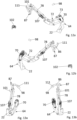
10a und b Seitenansichten eines Verdeckgestänges des Cabrioletverdecks in der Verdeckstellung von außen und von innen; -
11a und b den10a und b entsprechende Seitenansichten des Verdeckgestänges, jedoch in einer ersten Zwischenstellung beim Verstellen in die Ablagestellung; -
12a und b den10a und b entsprechende Seitenansichten des Verdeckgestänges, jedoch in einer zweiten Zwischenstellung beim Verstellen in die Ablagestellung; -
13a und b wiederum den10a und b entsprechende Seitenansichten des Verdeckgestänges vor dem Absenken in die Ablagestellung; -
14 eine perspektivische Heckansicht des Verdeckgestänges in der Verdeckstellung; -
15 eine Draufsicht auf das Verdeckgestänge in der Verdeckstellung; -
16 eine teiltransparente Darstellung des Verdeckgestänges in dessen Verdeckstellung; -
17 eine16 entsprechende Darstellung des Verdeckgestänges, jedoch in einer ersten Zwischenstellung beim Verstellen in die Ablagestellung; -
18 wiederum eine16 entsprechende Ansicht des Verdeckgestänges, jedoch in einer ungesicherten Ablagestellung; -
19 ebenfalls eine16 entsprechende Ansicht des Verdeckgestänges, jedoch in der gesicherten Ablagestellung; -
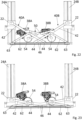
20 eine Heckansicht eines Hubmechanismus des Verdeckgestänges in der Verdeckstellung; -
21 eine20 entsprechende Ansicht des Hubmechanismus in einer ersten Zwischenstellung beim Absenken des Verdecks; -
22 wiederum eine20 entsprechende Ansicht des Hubmechanismus, jedoch in einer zweiten Zwischenstellung beim Absenken des Verdecks; und -
23 ebenfalls eine20 entsprechende Ansicht des Hubmechanismus, jedoch in der abgesenkten Ablagestellung des Verdecks.
-
1 a schematic, partial side view of a convertible vehicle with a convertible top according to the invention in its convertible top position; -
2 one1 corresponding view of the convertible top, but in an intermediate position when adjusted to a storage position; -
3 also a1 corresponding view of the convertible top, but in a further intermediate position when adjusted to the storage position; -
4 again a1 corresponding view of the convertible top, but in a further intermediate position when adjusted to the storage position; -
5 a side view of the convertible top in a storage position; -
6 an interior view of the convertible top in its convertible position; -
7 one6 corresponding interior view of the convertible top, but in an intermediate position when adjusting to the storage position; -
8 an interior view of the convertible top in the storage position, but in the unsecured state; -
9 one8 corresponding interior view of the convertible top, but in the secured state; -
10a and b side views of a convertible top rod in the convertible top position from the outside and from the inside; -
11a and b the10a and b corresponding side views of the convertible top linkage, but in a first intermediate position when adjusted to the storage position; -
12a and b the10a and b corresponding side views of the convertible top linkage, but in a second intermediate position when adjusted to the storage position; -
13a and b again the10a and b corresponding side views of the convertible top frame before lowering into the storage position; -
14 a perspective rear view of the convertible top frame in the convertible top position; -
15 a top view of the convertible top frame in the convertible top position; -
16 a partially transparent representation of the convertible top frame in its convertible top position; -
17 one16 corresponding representation of the convertible top frame, but in a first intermediate position when adjusting to the storage position; -
18 again a16 corresponding view of the convertible top frame, but in an unsecured storage position; -
19 also a16 corresponding view of the convertible top frame, but in the secured storage position; -
20 a rear view of a lifting mechanism of the convertible top linkage in the convertible top position; -
21 one20 corresponding view of the lifting mechanism in a first intermediate position when lowering the roof; -
22 again a20 corresponding view of the lifting mechanism, but in a second intermediate position when lowering the roof; and -
23 also a20 corresponding view of the lifting mechanism, but in the lowered storage position of the convertible top.
In der Zeichnung ist ein Cabriolet-Fahrzeug 10 dargestellt, das mit einem verstellbaren Verdeck 12 ausgestattet ist, welches zwischen einer in
Das Verdeck 12 ist als so genanntes RHT (Retractable Hard Top) ausgebildet und umfasst zwei starre Dachschalen 26 und 28, die Außenseiten haben, die in der Verdeckstellung in Fahrzeuglängsrichtung betrachtet flächenbündig hintereinander angeordnet sind und in der Ablagestellung in einer aufrechten Position derart in dem Verdeckablageraum 16 angeordnet sind, dass die bugseitige Dachschale 26 in Fahrzeugbugrichtung vor der heckseitigen Dachschale 28 angeordnet ist. Die in der Verdeckstellung in Richtung des Fahrzeugbugs weisenden Ränder der Dachschalen 26 und 28 weisen also nach oben. Die heckseitige Dachschale 28 übergreift hierbei die Außenseite der bugseitigen Dachschale 26 von hinten (vgl.
Um die Hauptlager 22 an den Führungsschienen 24A und 24B verstellen zu können, weist das Verdeck 12 eine als Hubmechanismus ausgebildete Antriebsanordnung 34 auf, welche eine Hebelanordnung 36 umfasst, die an die beiden Hauptlager 22 angelenkt ist und von zwei Antriebsmotoren 38A und 38B angetrieben ist (vgl.
Die Hebelanordnung 36 umfasst für die beiden Hauptlager 22 jeweils eine Hebeleinheit 40A bzw. 40B, die mittels des betreffenden Antriebsmotors 38A bzw. 38B antreibbar ist. Die Antriebsmotoren 38A und 38B sind synchron angetrieben, so dass die Hebeleinheiten 40A und 40B synchron verstellt werden können. Beispielsweise kann eine Synchronisierung durch Ineinandergreifen von Zahnrädern der beiden Hebeleinheiten 40A und 40B realisiert werden (nicht dargestellt). Denkbar ist es auch, dass die beiden Hebeleinheiten 40A und 40B durch einen gemeinsamen Antriebsmotor angetrieben sind.The
Die beiden Hebeleinheiten 40A und 40B umfassen jeweils eine Vielzahl von Lenkern, die in Fahrzeugquerrichtung bzw. Verdeckquerrichtung verschwenkbar sind. Insbesondere umfassen die Hebeleinheiten 40A und 40B jeweils einen Hauptlenker 42, der mit einem Ende an das jeweilige Hauptlager 22 angelenkt ist und mit seinem anderen Ende schwenkbar mit einem Gleiter 44 verbunden ist, der in einer betreffenden karosseriefest angeordneten und sich in Verdeckquerrichtung erstreckenden Führungsbahn 46 verschiebbar geführt ist. An die Hauptlenker 42 ist jeweils in einem Gelenkpunkt 48 eine Antriebslenkeranordnung 50 angelenkt, welche einen Antriebshebel 52 umfasst, der drehfest mit einem Zahnrad 54 verbunden ist, das von einem Antriebsritzel 56 des betreffenden Antriebsmotors 38A bzw. 38B antreibbar ist. Die Antriebshebel 52 sind jeweils an dem von dem betreffenden Zahnrad 54 abgewandten Ende über einen Gelenkpunkt 58 mit einem Lenker 60 der Antriebslenkeranordnung 50 verbunden, der in dem Gelenkpunkt 48 an den betreffenden Hauptlenker 42 angelenkt ist.The two
In einem weiteren Gelenkpunkt 61 ist an die Hauptlenker 42 jeweils ein Stützlenker 62 angelenkt, welcher wiederum an einen betreffenden Lagerbock 63 angelenkt ist, der karosseriefest bzw. ortsfest gegenüber den Führungsschienen 24A und 24B angeordnet ist. In der in
Wenn ausgehend von der in
Alternativ ist es auch denkbar, dass die Antriebslenkeranordnungen 50 jeweils an dem betreffenden Stützlenker 62 angelenkt sind. Ferner ist es auch denkbar, dass die Antriebslenkeranordnungen 50 nicht nur zwei, sondern auch drei oder mehr Lenker umfassen.Alternatively, it is also conceivable that the
Die beidseits der vertikalen Verdecklängsmittelebene angeordneten Lenkeranordnungen 20 des Verdeckgestänges 18 sind zumindest weitgehend spiegelsymmetrisch zueinander ausgebildet, weshalb nachfolgend im Wesentlichen nur auf die bezogen auf die Vorwärtsfahrtrichtung des Cabriolet-Fahrzeugs 10 links angeordnete Lenkeranordnung 20 Bezug genommen wird. Die bezogen auf die Vorwärtsfahrtrichtung des Cabriolet-Fahrzeugs 10 rechts angeordnete Lenkeranordnung ist in analoger Weise ausgebildet.The linkage assemblies 20 of the convertible top linkage 18 arranged on both sides of the vertical longitudinal center plane of the convertible top are at least largely mirror-symmetrical to one another, which is why reference is made below essentially only to the linkage assembly 20 arranged on the left with respect to the forward direction of travel of the
Ausgehend von den höhenverstellbaren Hauptlagern 22 umfassen die Lenkeranordnungen 20 jeweils eine Viergelenkanordnung 64, die eine erste Mehrgelenkanordnung bildet und die zwei Hauptlenker 65 und 66 umfasst, die schwenkbar an dem betreffenden Hauptlager 22 gelagert sind. Zudem umfasst die Viergelenkanordnung 64 einen als Antriebslenker ausgebildeten Koppellenker 67, welcher einerseits in einem Gelenkpunkt 68 an den Hauptlenker 66 angelenkt ist und andererseits in einem Drehpunkt 69 mit einem Antriebsritzel eines als Elektromotor ausgebildeten Antriebsmotors 70 verbunden ist, der an dem einen Trägerlenker darstellenden Hauptlenker 65 starr befestigt ist. Der Antriebsmotor 70 ist als Bestandteil der Viergelenkanordnung anzusehen. An dem Hauptlenker 65 ist die heckseitige Dachschale 28 befestigt.Starting from the height-adjustable
Die Viergelenkanordnung 64 ist mit einer eine zweite Mehrgelenkanordnung darstellenden Siebengelenkanordnung 72 gekoppelt, und zwar über einen Koppellenker 73, der einerseits in dem Gelenkpunkt 68 an die Viergelenkanordnung 64 angebunden ist und andererseits in einem Gelenkpunkt 74 mit einem Basislenker 75 der Siebengelenkanordnung 72 verbunden ist. Zur Ausbildung der Siebengelenkanordnung 72 ist der Basislenker 75 an einem Ende in einem Gelenkpunkt 76 an den Hauptlenker 65 der Viergelenkanordnung 64 angelenkt und an einem zweiten Ende in einem Gelenkpunkt 77 an einen doppelschaligen Trägerlenker 78 angelenkt, welcher in der Verdeckstellung des Verdecks 12 bugseitig angeordnet ist und an dem die vordere Dachschale 26 gelagert ist. Der Basislenker 75 ist leicht gewinkelt und weist an seinem Knickpunkt einen Gelenkpunkt 79 auf, in welchem ein Koppellenker 59 angelenkt ist, der in einem Gelenkpunkt 80 an einen weiteren Basislenker 81 der Siebengelenkanordnung 72 angelenkt ist, der in einem Gelenkpunkt 82 an den Hauptlenker 65 der Viergelenkanordnung 64 angelenkt ist. Der Basislenker 81 weist an seinem dem Hauptlenker 65 abgewandten Ende einen weiteren Gelenkpunkt 83 auf, über den er mit einem Zwischenlenker 84 verbunden ist, der in einem Gelenkpunkt 85 mit dem Trägerlenker 78 verbunden ist. Die beiden Basislenker 75 und 81, der Hauptlenker 65, der Koppellenker 59, der Zwischenlenker 84 und der Trägerlenker 78 bilden so über die beschriebenen Gelenkpunkte 76, 77, 79, 80, 82, 83 und 85 die Siebengelenkanordnung 72 aus.The four-
Mittels der Viergelenkanordnung 64 und der Siebengelenkanordnung 72 ist es möglich, durch Betätigung des Antriebsmotors 70 ausgehend von der in
Die beiden Lenkeranordnungen 20 sind des Weiteren jeweils mit einem Anschlaglenker 86 versehen, der Bestandteil einer Anschlaglenkeranordnung 87 ist. Die Anschlaglenkeranordnung 87 bildet mit dem Trägerlenker 78 eine Viergelenkanordnung und umfasst neben dem Anschlaglenker 86, der in einem Gelenkpunkt 88 an dem Trägerlenker 78 schwenkbar gelagert ist, einen in einem Gelenkpunkt 89 an dem Trägerlenker 78 gelagerten Lenker 90, welcher an seinem dem Gelenkpunkt 89 abgewandten Ende über einen Gelenkpunkt 91 mit einer Koppel 92 verbunden ist, die in einem Gelenkpunkt 93 an den Anschlaglenker 86 angelenkt ist. Der Anschlaglenker 86 hat stirnseitig eine gabelartige Anschlagfläche 97, welche die Wirkfläche des Anschlaglenkers 86 darstellt.The two link assemblies 20 are further each provided with a
Zur Betätigung ist der Lenker 90 der Anschlaglenkeranordnung 87 in einem Gelenkpunkt 94 mit einer Antriebsstange 95 verbunden, die mit ihrem der Anschlaglenkeranordnung 87 abgewandten Ende in einem Gelenkpunkt 96 mit dem Zwischenlenker 84 der Siebengelenkanordnung 72 verbunden ist. Über die Antriebsstange 95 kann der Anschlaglenker 86 aus seiner in
Zur Sicherung des Verdecks 12 in der Verdeckstellung ist an den beidseits angeordneten Lenkeranordnungen 20 jeweils eine Verschlusseinrichtung 100 vorgesehen, die einen vorderen Riegelhaken 101 umfasst, dessen Schwenkachse mit der Schwenkachse des Anschlaglenkers 86 zusammenfällt, das heißt, der also ebenfalls um die durch den Gelenkpunkt 88 definierte Schwenkachse schwenkbar ist und in seiner in
Um in der Ablagestellung die beiden Dachschalen 26 und 28 aneinander zu sichern, weisen die beidseits angeordneten Lenkeranordnungen 20 des Weiteren einen Anschlagriegel 111 auf, der in einem Gelenkpunkt 112 an der Koppel 92 der Anschlaglenkeranordnung 87 schwenkbar gelagert ist und über einen Gelenkpunkt 113 mit einem Koppellenker 114 verbunden ist, der in einem Gelenkpunkt 115 an den Riegelhaken 101 angelenkt ist. Durch Betätigung des Frontverschlussantriebs 107 ist es also möglich, über die Riegelstange 104, den Riegelhaken 101 und den Koppellenker 114 den Anschlagriegel 111 zwischen einer Freigabestellung (vgl.
BezugszeichenlisteList of reference symbols
- 1010
- Cabriolet-Fahrzeugconvertible vehicle
- 1212
- Verdeckconvertible top
- 1414
- FahrzeuginnenraumVehicle interior
- 1616
- VerdeckablageraumConvertible top storage space
- 1818
- VerdeckgestängeConvertible top frame
- 2020
- LenkeranordnungHandlebar arrangement
- 2222
- HauptlagerMain bearing
- 24A, B24A, B
- Führungsschieneguide rail
- 2626
- Dachschaleroof shell
- 2828
- Dachschaleroof shell
- 3030
- vorderer Windlauffront cowl
- 3232
- Windschutzscheibewindshield
- 3434
- AntriebsanordnungDrive arrangement
- 3636
- HebelanordnungLever arrangement
- 38A, B38A, B
- Antriebsmotordrive motor
- 40A, B40A, B
- HebeleinheitLever unit
- 4242
- HauptlenkerMain handlebar
- 4444
- Gleiterglider
- 4646
- Führungsbahnguideway
- 4848
- Gelenkpunktarticulation point
- 5050
- AntriebslenkeranordnungDrive link arrangement
- 5252
- Antriebshebeldrive lever
- 5454
- Zahnradgear
- 5656
- Antriebsritzeldrive pinion
- 5858
- Gelenkpunktarticulation point
- 5959
- Koppellenkercoupling link
- 6060
- Lenkerhandlebar
- 6161
- Gelenkpunktarticulation point
- 6262
- StützlenkerSupport arm
- 6363
- Lagerbockbearing block
- 6464
- ViergelenkanordnungFour-bar arrangement
- 6565
- HauptlenkerMain handlebar
- 6666
- HauptlenkerMain handlebar
- 6767
- Koppellenkercoupling link
- 6868
- Gelenkpunktarticulation point
- 6969
- DrehpunktPivot point
- 7070
- Antriebsmotordrive motor
- 7272
- SiebengelenkanordnungSeven-joint arrangement
- 7373
- Koppellenkercoupling link
- 7474
- Gelenkpunktarticulation point
- 7575
- BasislenkerBase handlebar
- 7676
- Gelenkpunktarticulation point
- 7777
- Gelenkpunktarticulation point
- 7878
- TrägerlenkerCarrier handlebar
- 7979
- Gelenkpunktarticulation point
- 8080
- Gelenkpunktarticulation point
- 8181
- BasislenkerBase handlebar
- 8282
- Gelenkpunktarticulation point
- 8383
- Gelenkpunktarticulation point
- 8484
- Zwischenlenkerintermediate link
- 8585
- Gelenkpunktarticulation point
- 8686
- Anschlaglenkerstop handlebar
- 8787
- AnschlaglenkeranordnungStop link arrangement
- 8888
- Gelenkpunktarticulation point
- 8989
- Gelenkpunktarticulation point
- 9090
- Lenkerhandlebar
- 9191
- Gelenkpunktarticulation point
- 9292
- Koppelpaddock
- 9393
- Gelenkpunktarticulation point
- 9494
- Gelenkpunktarticulation point
- 9595
- Antriebsstangedrive rod
- 9696
- Gelenkpunktarticulation point
- 9797
- AnschlagflächeStop surface
- 9898
- GegenanschlagelementCounter stop element
- 100100
- Verschlusseinrichtunglocking device
- 101101
- RiegelhakenLatch hook
- 102102
- Riegelelementlocking element
- 103103
- Gelenkpunktarticulation point
- 104104
- Riegelstangelocking bar
- 105105
- Gelenkpunktarticulation point
- 106106
- Antriebshebeldrive lever
- 107107
- FrontverschlussantriebFront shutter drive
- 108108
- Verschlussstangelocking bar
- 109109
- Gelenkpunktarticulation point
- 110110
- Verschlusshakenlocking hook
- 111111
- Anschlagriegelstop bolt
- 112112
- Gelenkpunktarticulation point
- 113113
- Gelenkpunktarticulation point
- 114114
- Koppellenkercoupling link
- 115115
- Gelenkpunktarticulation point
ZITATE ENTHALTEN IN DER BESCHREIBUNGQUOTES CONTAINED IN THE DESCRIPTION
Diese Liste der vom Anmelder aufgeführten Dokumente wurde automatisiert erzeugt und ist ausschließlich zur besseren Information des Lesers aufgenommen. Die Liste ist nicht Bestandteil der deutschen Patent- bzw. Gebrauchsmusteranmeldung. Das DPMA übernimmt keinerlei Haftung für etwaige Fehler oder Auslassungen.This list of documents submitted by the applicant was generated automatically and is included solely for the convenience of the reader. This list is not part of the German patent or utility model application. The DPMA assumes no liability for any errors or omissions.
Zitierte PatentliteraturCited patent literature
-
DE 102 94 214 B4 [0002]
DE 102 94 214 B4 [0002]
Claims (7)
Priority Applications (1)
| Application Number | Priority Date | Filing Date | Title |
|---|---|---|---|
| US18/971,473 US20250206110A1 (en) | 2023-12-22 | 2024-12-06 | Convertible top having coupled multi-bar arrangements |
Applications Claiming Priority (2)
| Application Number | Priority Date | Filing Date | Title |
|---|---|---|---|
| DE102023136565.7 | 2023-12-22 | ||
| DE102023136565 | 2023-12-22 |
Publications (1)
| Publication Number | Publication Date |
|---|---|
| DE102024103222A1 true DE102024103222A1 (en) | 2025-06-26 |
Family
ID=95938592
Family Applications (1)
| Application Number | Title | Priority Date | Filing Date |
|---|---|---|---|
| DE102024103222.7A Pending DE102024103222A1 (en) | 2023-12-22 | 2024-02-06 | Convertible top with coupled multi-joint arrangements |
Country Status (2)
| Country | Link |
|---|---|
| US (1) | US20250206110A1 (en) |
| DE (1) | DE102024103222A1 (en) |
-
2024
- 2024-02-06 DE DE102024103222.7A patent/DE102024103222A1/en active Pending
- 2024-12-06 US US18/971,473 patent/US20250206110A1/en active Pending
Also Published As
| Publication number | Publication date |
|---|---|
| US20250206110A1 (en) | 2025-06-26 |
Similar Documents
| Publication | Publication Date | Title |
|---|---|---|
| EP1112879B1 (en) | Convertible vehicle roof | |
| DE10019366C2 (en) | Roof construction for a motor vehicle with a removable roof | |
| EP1364823B1 (en) | Convertible vehicle with tiltable roof storable under a panel element | |
| DE60122558T2 (en) | RETRACTABLE VEHICLE ROOF WITH SWIVEL ELEMENTS | |
| EP1331122B1 (en) | Retractable hardtop vehicle roof | |
| DE10326981B4 (en) | Vehicle convertible from a pickup to a convertible | |
| DE10143823A1 (en) | Motor vehicle roof with opening and roof lid with holder elements sliding in non-parallel guide rails | |
| EP1904327A2 (en) | Adjusting mechanism of a soft top compartment cover of a convertible | |
| DE102017102598B4 (en) | Convertible top with panel bows | |
| DE102005043511A1 (en) | Cabriolet vehicle with retractable in a top compartment vehicle roof | |
| EP1656275B1 (en) | Cabriolet | |
| DE102024103222A1 (en) | Convertible top with coupled multi-joint arrangements | |
| DE102020121341B4 (en) | Convertible top compartment cover arrangement with handlebar arrangement and locking arrangement | |
| EP1780065B1 (en) | Hardtop vehicle roof with externally arranged roof kinematic | |
| EP1940640B1 (en) | Locking mechanism for a folding top compartment cover of a convertible | |
| DE102007047457B4 (en) | Adjustable roof part of an openable vehicle roof | |
| EP1554144A2 (en) | Motor vehicle | |
| DE102024103228A1 (en) | Convertible top with roof frame | |
| DE102004055404A1 (en) | Vehicle roof has lateral bars essentially parallel to central bridge on both sides, pivotable about axis in direction of travel into rest position, cover movable in guide rails to expose respective roof openings on both sides of bridge | |
| DE102024103221A1 (en) | Convertible top with roof skin arrangement and roof frame | |
| DE10258330B4 (en) | Retractable vehicle roof | |
| DE10065248B4 (en) | Swiveling and sliding rear window | |
| DE102004046678B4 (en) | Movable vehicle roof has first roof part that can be pivoted about vertical joint axis between front position and rear position closer to rear of vehicle | |
| DE102017012224B3 (en) | Roof structure for a motor vehicle | |
| DE19714106A1 (en) | Convertible roof for vehicle |
Legal Events
| Date | Code | Title | Description |
|---|---|---|---|
| R012 | Request for examination validly filed | ||
| R079 | Amendment of ipc main class |
Free format text: PREVIOUS MAIN CLASS: B60J0007047000 Ipc: B60J0007140000 |