DE102023206574A1 - Capacitor device, capacitor apparatus, motor vehicle and method for producing a capacitor device - Google Patents
Capacitor device, capacitor apparatus, motor vehicle and method for producing a capacitor device Download PDFInfo
- Publication number
- DE102023206574A1 DE102023206574A1 DE102023206574.6A DE102023206574A DE102023206574A1 DE 102023206574 A1 DE102023206574 A1 DE 102023206574A1 DE 102023206574 A DE102023206574 A DE 102023206574A DE 102023206574 A1 DE102023206574 A1 DE 102023206574A1
- Authority
- DE
- Germany
- Prior art keywords
- capacitor
- capacitor device
- intermediate circuit
- busbar
- housing
- Prior art date
- Legal status (The legal status is an assumption and is not a legal conclusion. Google has not performed a legal analysis and makes no representation as to the accuracy of the status listed.)
- Pending
Links
Images





Classifications
-
- H—ELECTRICITY
- H01—ELECTRIC ELEMENTS
- H01G—CAPACITORS; CAPACITORS, RECTIFIERS, DETECTORS, SWITCHING DEVICES, LIGHT-SENSITIVE OR TEMPERATURE-SENSITIVE DEVICES OF THE ELECTROLYTIC TYPE
- H01G2/00—Details of capacitors not covered by a single one of groups H01G4/00-H01G11/00
- H01G2/02—Mountings
-
- H—ELECTRICITY
- H01—ELECTRIC ELEMENTS
- H01G—CAPACITORS; CAPACITORS, RECTIFIERS, DETECTORS, SWITCHING DEVICES, LIGHT-SENSITIVE OR TEMPERATURE-SENSITIVE DEVICES OF THE ELECTROLYTIC TYPE
- H01G4/00—Fixed capacitors; Processes of their manufacture
- H01G4/002—Details
- H01G4/224—Housing; Encapsulation
-
- H—ELECTRICITY
- H01—ELECTRIC ELEMENTS
- H01G—CAPACITORS; CAPACITORS, RECTIFIERS, DETECTORS, SWITCHING DEVICES, LIGHT-SENSITIVE OR TEMPERATURE-SENSITIVE DEVICES OF THE ELECTROLYTIC TYPE
- H01G4/00—Fixed capacitors; Processes of their manufacture
- H01G4/002—Details
- H01G4/228—Terminals
- H01G4/236—Terminals leading through the housing, i.e. lead-through
-
- H—ELECTRICITY
- H01—ELECTRIC ELEMENTS
- H01G—CAPACITORS; CAPACITORS, RECTIFIERS, DETECTORS, SWITCHING DEVICES, LIGHT-SENSITIVE OR TEMPERATURE-SENSITIVE DEVICES OF THE ELECTROLYTIC TYPE
- H01G4/00—Fixed capacitors; Processes of their manufacture
- H01G4/38—Multiple capacitors, i.e. structural combinations of fixed capacitors
-
- H—ELECTRICITY
- H01—ELECTRIC ELEMENTS
- H01G—CAPACITORS; CAPACITORS, RECTIFIERS, DETECTORS, SWITCHING DEVICES, LIGHT-SENSITIVE OR TEMPERATURE-SENSITIVE DEVICES OF THE ELECTROLYTIC TYPE
- H01G4/00—Fixed capacitors; Processes of their manufacture
- H01G4/40—Structural combinations of fixed capacitors with other electric elements, the structure mainly consisting of a capacitor, e.g. RC combinations
Landscapes
- Engineering & Computer Science (AREA)
- Power Engineering (AREA)
- Microelectronics & Electronic Packaging (AREA)
- Manufacturing & Machinery (AREA)
- Inverter Devices (AREA)
Abstract
Eine Kondensatoreinrichtung (100) für eine Kondensatorvorrichtung für einen Wechselrichter eines Kraftfahrzeugs weist zumindest einen Kondensator (105), ein Gehäuse (115), eine erste Stromschiene (110) und eine zweite Stromschiene (120) auf. Das Gehäuse (115) ist ausgebildet, um den zumindest einen Kondensator (105) aufzunehmen. Die erste Stromschiene (110) und die zweite Stromschiene (120) sind zum elektrischen Kontaktieren der Kondensatoreinrichtung (100) ausgebildet. Dabei ist der Kondensator (105) zwischen der ersten Stromschiene (110) und der zweiten Stromschiene (120) elektrisch kontaktiert oder kontaktierbar.
Description
Die vorliegende Erfindung bezieht sich auf eine Kondensatoreinrichtung, eine Kondensatorvorrichtung, ein Kraftfahrzeug und auf ein Verfahren zum Herstellen einer Kondensatoreinrichtung.The present invention relates to a capacitor device, a capacitor apparatus, a motor vehicle and a method for producing a capacitor device.
Es sind Kondensatorvorrichtungen bekannten, bei denen die Kondensatoreinrichtung und ein Zwischenkreiskondensator in einem gemeinsamen Gehäuse angeordnet sein können. Eine Anbindung der Kondensatoreinrichtung an Stromschienen kann im Inneren des Gehäuses erfolgen.Capacitor devices are known in which the capacitor device and an intermediate circuit capacitor can be arranged in a common housing. The capacitor device can be connected to busbars inside the housing.
Vor diesem Hintergrund schafft die vorliegende Erfindung eine verbesserte Kondensatoreinrichtung, eine verbesserte Kondensatorvorrichtung, ein verbessertes Kraftfahrzeug und ein verbessertes Verfahren zum Herstellen einer Kondensatoreinrichtung gemäß den Hauptansprüchen. Vorteilhafte Ausgestaltungen ergeben sich aus den Unteransprüchen und der nachfolgenden Beschreibung.Against this background, the present invention provides an improved capacitor device, an improved capacitor apparatus, an improved motor vehicle and an improved method for producing a capacitor device according to the main claims. Advantageous embodiments emerge from the subclaims and the following description.
Die mit dem vorgestellten Ansatz erreichbaren Vorteile bestehen insbesondere darin, dass eine Kondensatoreinrichtung geschaffen wird, die zuverlässig, schnell und einfach mit einem benachbarten Zwischenkreiskondensator gekoppelt werden kann.The advantages that can be achieved with the approach presented are in particular that a capacitor device is created that can be reliably, quickly and easily coupled to an adjacent intermediate circuit capacitor.
Eine Kondensatoreinrichtung für eine Kondensatorvorrichtung für einen Wechselrichter eines Kraftfahrzeugs weist zumindest einen Kondensator, ein Gehäuse, eine erste Stromschiene und eine zweite Stromschiene auf. Das Gehäuse ist ausgebildet, um den zumindest einen Kondensators aufzunehmen. Die erste Stromschiene und die zweite Stromschiene sind zum elektrischen Kontaktieren der Kondensatoreinrichtung ausgebildet. Dabei ist der Kondensator zwischen der ersten Stromschiene und der zweiten Stromschiene elektrisch kontaktiert oder kontaktierbar.A capacitor device for a capacitor apparatus for an inverter of a motor vehicle has at least one capacitor, a housing, a first busbar and a second busbar. The housing is designed to accommodate the at least one capacitor. The first busbar and the second busbar are designed to electrically contact the capacitor device. The capacitor is or can be electrically contacted between the first busbar and the second busbar.
Bei dem Kondensator kann es sich um einen elektrischen Kondensator handeln, der beispielsweise in einem Zwischenkreis eines Wechselrichters angeordnet werden kann. Der Wechselrichter kann ein elektrisches Gerät sein, das Gleichspannung in Wechselspannung umwandelt. Das Kraftfahrzeug kann beispielsweise ein Kraftfahrzeug mit einem elektrischen Antrieb sein. Die zweite Stromschiene kann zumindest teilweise aus dem Gehäuse ragen. Ferner kann die erste Stromschiene und/oder die zweite Stromschiene eine Kontaktierung für eine Leiterplatte ausformen, wodurch eine direkte Kontaktierungsmöglichkeit an die Leiterplatte ermöglicht werden kann.The capacitor can be an electrical capacitor that can be arranged, for example, in an intermediate circuit of an inverter. The inverter can be an electrical device that converts direct current into alternating current. The motor vehicle can be, for example, a motor vehicle with an electric drive. The second busbar can protrude at least partially from the housing. Furthermore, the first busbar and/or the second busbar can form a contact for a circuit board, which can enable a direct contact to the circuit board.
Die Kondensatoreinrichtung kann einen weiteren Kondensator aufweisen, der in dem Gehäuse angeordnet oder anordenbar ist. Zusätzlich kann die Kondensatoreinrichtung eine dritte Stromschiene zum elektrischen Kontaktieren der Kondensatoreinrichtung aufweisen. Dabei kann der weitere Kondensator zwischen der ersten Stromschiene und der dritten Stromschiene elektrisch kontaktiert oder kontaktierbar sein. Die zweite Stromschiene und die dritte Stromschiene können elektrisch voneinander isoliert oder isolierbar sein. Die dritte Stromschiene kann zumindest teilweise aus dem Gehäuse ragen. Ferner kann die dritte Stromschiene eine Kontaktierung für eine Leiterplatte ausformen, wodurch eine direkte Kontaktierungsmöglichkeit an die Leiterplatte ermöglicht werden kann.The capacitor device can have a further capacitor that is arranged or can be arranged in the housing. In addition, the capacitor device can have a third busbar for electrically contacting the capacitor device. The further capacitor can be electrically contacted or contactable between the first busbar and the third busbar. The second busbar and the third busbar can be electrically insulated from one another or can be insulated. The third busbar can protrude at least partially from the housing. Furthermore, the third busbar can form a contact for a circuit board, which can enable a direct contact to the circuit board.
Das Gehäuse kann einen Schraubdom ausformen, der mit der ersten Stromschiene über ein Verbindungselement verbunden oder verbindbar sein kann. Der Schraubdom kann als ein Masseanschluss ausgebildet sein. Bei dem Verbindungselement kann es sich um eine Schraube handeln, die kostengünstig und schnell hergestellt werden kann. Die erste Stromschiene kann zuverlässig innerhalb oder an dem Gehäuse und/oder dem Kondensator und/oder dem weiteren Kondensator angeordnet werden.The housing can form a screw dome that can be connected or connectable to the first busbar via a connecting element. The screw dome can be designed as a ground connection. The connecting element can be a screw that can be manufactured inexpensively and quickly. The first busbar can be reliably arranged within or on the housing and/or the capacitor and/or the further capacitor.
Der Kondensator kann als ein Y-Kondensator verschaltet oder verschaltbar sein. Der weitere Kondensator kann ebenfalls als ein Y-Kondensator verschaltet oder verschaltbar sein. Vorteilhafterweise können die Kondensatoren kostengünstig und in großer Stückzahl hergestellt werden. Die Y-Kondensatoren können hochfrequente Störsignale gegen Masse ableiten. Beispielsweise werden jeweils ein Y-Kondensatoren zwischen DC+ und Masse und zwischen DC- und Masse angeschlossen.The capacitor can be connected or connectable as a Y capacitor. The other capacitor can also be connected or connectable as a Y capacitor. Advantageously, the capacitors can be manufactured inexpensively and in large quantities. The Y capacitors can divert high-frequency interference signals to ground. For example, one Y capacitor is connected between DC+ and ground and one between DC- and ground.
Die Kondensatoreinrichtung kann zumindest ein Koppelelement aufweisen, das an dem Gehäuse angeordnet sein kann. Das zumindest eine Koppelelement kann ausgeformt sein, um die Kondensatoreinrichtung mit einem Gegenkoppelelement eines benachbarten Zwischenkreiskondensators zu koppeln. Zusätzlich oder alternativ kann die Kondensatoreinrichtung zumindest ein Gegenkoppelelement aufweisen, das an dem Gehäuse angeordnet sein kann. Das zumindest eine Gegenkoppelelement kann ausgeformt sein, um die Kondensatoreinrichtung mit einem Koppelelement des benachbarten Zwischenkreiskondensators zu koppeln. Das Koppelelement kann einen Pin, einen Vorsprung oder einen Überstand, und zusätzlich oder alternativ eine Aufnahmeöffnung oder Durchgangsöffnung ausformen. Vorteilhafterweise kann dadurch eine einfache Handhabung ermöglicht werden. Das Koppelelement und zusätzlich oder alternativ das Gegenkoppelelement können zumindest teilweise von dem Gehäuse hervorragen. Vorteilhafterweise kann dadurch eine besonders stabile Kopplung ermöglicht werden. Wenn das Koppelelement zum Koppeln der Kondensatoreinrichtung mit einem Trägerelement verwendet wird, kann beispielsweise eine Bewegung der Kondensatoreinrichtung gegenüber dem Koppelelement in zumindest einer Bewegungsrichtung blockiert werden. Die Kondensatoreinrichtung kann mehrere Koppelelemente aufweisen. Beispielsweise kann ein Koppelelement zum Koppeln der Kondensatoreinrichtung mit einem benachbarten Zwischenkreiskondensator verwendet werden und ein weiteres Koppelelement kann zum Koppeln der Kondensatoreinrichtung mit einem Trägerelement oder mit einem weiteren Zwischenkreiskondensator verwendet werden. Es können auch mehrere, beispielsweise zwei Koppelelemente zum Koppeln der Kondensatoreinrichtung mit dem benachbarten Zwischenkreiskondensator verwendet werden. Mehrere Koppelelemente einer Kondensatoreinrichtung können identisch oder zumindest teilweise unterschiedlich ausgeformt sein. Eine Form des Gegenkoppelelements kann einer Form des Koppelements angepasst sein. Entsprechend zu dem Koppelement kann die Kondensatoreinrichtung eine Mehrzahl identischer oder zumindest teilweise unterschiedlich ausgeformter Gegenkoppelelemente aufweisen. Dabei kann ein weiteres Gegenkoppelelement der Kondensatoreinrichtung ausgeformt sein, um die Kondensatoreinrichtung mit einem Koppelement eines weiteren Zwischenkreiskondensators zu koppeln. Das Gegenkoppelement und das weitere Gegenkoppelement können diagonal zueinander an dem Gehäuse der Kondensatoreinrichtung angeordnet sein. Das Koppelement und ein weiteres Koppelement können beispielsweise ebenfalls diagonal zueinander an dem Gehäuse der Kondensatoreinrichtung angeordnet sein.The capacitor device can have at least one coupling element that can be arranged on the housing. The at least one coupling element can be shaped to couple the capacitor device to a counter-coupling element of an adjacent intermediate circuit capacitor. Additionally or alternatively, the capacitor device can have at least one counter-coupling element that can be arranged on the housing. The at least one counter-coupling element can be shaped to couple the capacitor device to a coupling element of the adjacent intermediate circuit capacitor. The coupling element can form a pin, a projection or a protrusion, and additionally or alternatively a receiving opening or through-opening. This can advantageously enable easy handling. The coupling element and additionally or alternatively the counter-coupling element can protrude at least partially from the housing. This can advantageously enable a particularly stable coupling. If the coupling element for coupling the If a capacitor device with a carrier element is used, for example, a movement of the capacitor device relative to the coupling element can be blocked in at least one direction of movement. The capacitor device can have a plurality of coupling elements. For example, one coupling element can be used to couple the capacitor device to an adjacent intermediate circuit capacitor and a further coupling element can be used to couple the capacitor device to a carrier element or to a further intermediate circuit capacitor. Several, for example two, coupling elements can also be used to couple the capacitor device to the adjacent intermediate circuit capacitor. Several coupling elements of a capacitor device can be identical or at least partially differently shaped. A shape of the counter-coupling element can be adapted to a shape of the coupling element. Corresponding to the coupling element, the capacitor device can have a plurality of identical or at least partially differently shaped counter-coupling elements. A further counter-coupling element of the capacitor device can be shaped in order to couple the capacitor device to a coupling element of a further intermediate circuit capacitor. The counter-coupling element and the further counter-coupling element can be arranged diagonally to one another on the housing of the capacitor device. The coupling element and a further coupling element can, for example, also be arranged diagonally to one another on the housing of the capacitor device.
Das Koppelelement der Kondensatoreinrichtung kann an einem Deckel des Gehäuses angeordnet sein und das Gegenkoppelelement der Kondensatoreinrichtung kann an einem dem Deckel gegenüberliegenden Boden des Gehäuses angeordnet sein. Benachbart zu dem Gegenkoppelement kann die Kondensatoreinrichtung ein zweites Gegenkoppelelement aufweisen. Dadurch können Zwischenkreiskondensatoren beispielsweise durch einfaches Aneinanderschieben mit der Kondensatoreinrichtung gekoppelt werden. Zusätzlich oder alternativ kann das Koppelelement ausgeformt sein, um die Kondensatoreinrichtung formschlüssig oder kraftschlüssig mit dem benachbarten Zwischenkreiskondensator zu koppeln. Vorteilhafterweise kann dadurch eine platzsparende und schnelle Montierung der Kondensatoreinrichtung ermöglicht werden. Das Koppelelement kann dazu beispielsweise als ein Haltebügel, eine Schwalbenschwanzverbindung, eine Schraubverbindung oder ein Rahmen ausgeformt sein. Vorteilhafterweise können somit universell einsetzbare Befestigungsmöglichkeiten genutzt werden. Ein weiteres Gegenkoppelement kann diagonal zu dem Gegenkoppelement und dem zweiten Gegenkoppelelement an dem Deckel des Gehäuses angeordnet sein.The coupling element of the capacitor device can be arranged on a cover of the housing and the counter-coupling element of the capacitor device can be arranged on a base of the housing opposite the cover. The capacitor device can have a second counter-coupling element adjacent to the counter-coupling element. This allows intermediate circuit capacitors to be coupled to the capacitor device, for example, by simply pushing them together. Additionally or alternatively, the coupling element can be shaped to couple the capacitor device to the adjacent intermediate circuit capacitor in a form-fitting or force-fitting manner. This advantageously enables space-saving and quick assembly of the capacitor device. The coupling element can be shaped as a retaining bracket, a dovetail connection, a screw connection or a frame, for example. This advantageously allows universally applicable fastening options to be used. A further counter-coupling element can be arranged diagonally to the counter-coupling element and the second counter-coupling element on the cover of the housing.
Eine Kondensatorvorrichtung weist eine Ausführungsform einer hierin genannten Kondensatoreinrichtung und einen benachbarten Zwischenkreiskondensator auf. Die Kondensatoreinrichtung ist mit dem benachbarten Zwischenkreiskondensators gekoppelt oder koppelbar. Vorteilhafterweise kann die Kondensatorvorrichtung ohne separate Fixierungsbauteile realisiert werden, wodurch Kosten und Zeit eingespart werden können. Der hier vorgestellte Ansatz kann daher auch als ein Mechanik-Konzept für eine modulare Y-Kondensatorbaugruppe verstanden werden. In anderen Worten ausgedrückt kann die Y-Kondensatorbaugruppe als modulare Ausführung mit elektromagnetischer verträglichkeits-, kurz EMV, optimierter Anbindung in Modularen Zwischenkreiskondensator integrierbar sein.A capacitor device has an embodiment of a capacitor device mentioned herein and an adjacent intermediate circuit capacitor. The capacitor device is coupled or can be coupled to the adjacent intermediate circuit capacitor. Advantageously, the capacitor device can be implemented without separate fixing components, which can save costs and time. The approach presented here can therefore also be understood as a mechanical concept for a modular Y-capacitor assembly. In other words, the Y-capacitor assembly can be integrated into the modular intermediate circuit capacitor as a modular design with an electromagnetic compatibility (EMC) optimized connection.
Der Zwischenkreiskondensator kann als ein X-Kondensator verschaltet oder verschaltbar sein. Vorteilhafterweise kann der Kondensator kostengünstig und in großer Stückzahl hergestellt werden. Ein X-Kondensator kann ausgebildet sein, um Störsignale auf Netzzuleitungen von Geräten abzublocken und zu bedämpfen. Der X-Kondensator kann ein elektrischer Kondensator sein, der zwischen Phase und Neutralleiter oder zwischen zwei Phasen geschaltet werden kann.The intermediate circuit capacitor can be connected or connectable as an X capacitor. Advantageously, the capacitor can be manufactured inexpensively and in large quantities. An X capacitor can be designed to block and dampen interference signals on the power supply lines of devices. The X capacitor can be an electrical capacitor that can be connected between the phase and neutral conductor or between two phases.
Die Kondensatorvorrichtung kann eine Mehrzahl von Zwischenkreiskondensatoren aufweisen. Dabei kann die Kondensatoreinrichtung zwischen den Zwischenkreiskondensatoren und zusätzlich oder alternativ benachbart zu mehreren Zwischenkreiskondensatoren gekoppelt oder koppelbar sein. Die Zwischenkreiskondensatoren können beispielsweise in beliebiger Reihenfolge in einer Reihe angeordnet werden. Dabei kann die Kondensatoreinrichtung in beliebiger Anordnung mit einem der Zwischenkreiskondensatoren oder mehreren Zwischenkreiskondensatoren gekoppelt sein.The capacitor device can have a plurality of intermediate circuit capacitors. The capacitor device can be coupled or can be coupled between the intermediate circuit capacitors and additionally or alternatively adjacent to several intermediate circuit capacitors. The intermediate circuit capacitors can, for example, be arranged in a row in any order. The capacitor device can be coupled in any arrangement to one of the intermediate circuit capacitors or to several intermediate circuit capacitors.
Die Kondensatorvorrichtung kann eine weitere Kondensatoreinrichtung aufweisen. Der zumindest eine Zwischenkreiskondensator kann zwischen der Kondensatoreinrichtung und der weiteren Kondensatoreinrichtung gekoppelt oder koppelbar sein. Es können mehrere Zwischenkreiskondensatoren zwischen oder benachbart zu den Kondensatoreinrichtungen gekoppelt sein.The capacitor device can have a further capacitor device. The at least one intermediate circuit capacitor can be coupled or can be coupled between the capacitor device and the further capacitor device. Several intermediate circuit capacitors can be coupled between or adjacent to the capacitor devices.
Die Kondensatorvorrichtung kann vorteilhafterweise im Zusammenhang mit einem Stromrichter verwendet werden.The capacitor device can advantageously be used in conjunction with a power converter.
Daneben betrifft die Erfindung einen elektrischen Achsantrieb für ein Kraftfahrzeug mit wenigstens einer elektrischen Maschine, einer Getriebeeinrichtung und einer Ausführungsform eines hierin beschriebenen Stromrichters.In addition, the invention relates to an electric axle drive for a motor vehicle with at least one electric machine, a transmission device and an embodiment of a power converter described herein.
Der Stromrichter kann als ein Wechselrichter oder Inverter ausgeführt sein. Unter Verwendung des Stromrichters kann ein zum Betreiben der elektrischen Maschine erforderlicher elektrischer Wechselstrom bereitgestellt werden. Unter Verwendung der Getriebeeinrichtung kann ein von der elektrischen Maschine bereitgestelltes Drehmoment in ein Antriebsmoment zum Antreiben zumindest eines Rads des Kraftfahrzeugs umgewandelt werden. Die Getriebeeinrichtung kann ein Getriebe zum Reduzieren der Drehzahl der elektrischen Maschine sowie optional ein Differenzial aufweisen.The power converter can be designed as a power inverter. Using the power converter, an alternating electrical current required to operate the electrical machine can be provided. Using the transmission device, a torque provided by the electrical machine can be converted into a drive torque for driving at least one wheel of the motor vehicle. The transmission device can have a transmission for reducing the speed of the electrical machine and optionally a differential.
Daneben betrifft die Erfindung ein Kraftfahrzeug mit einer Ausführungsform eines hierin genannten Stromrichters und zusätzlich oder alternativ mit einer Ausführungsform eines hierin genannten elektrischen Achsantriebs.In addition, the invention relates to a motor vehicle with an embodiment of a power converter mentioned herein and additionally or alternatively with an embodiment of an electric axle drive mentioned herein.
Ein Verfahren zum Herstellen einer Ausführungsform einer hierin genannten Kondensatoreinrichtung umfasst einen Schritt des Bereitstellens des zumindest einen Kondensators, des Gehäuses, der ersten Stromschiene und der zweiten Stromschiene. Zusätzlich umfasst das Verfahren einen Schritt des Anordnens des zumindest einen Kondensators in dem Gehäuse. Das Verfahren umfasst außerdem einen Schritt des Anbringens der ersten Stromschiene und der zweiten Stromschiene an dem zumindest einen Kondensator, um die Kondensatoreinrichtung herzustellen. Auch durch eine solche Ausführungsform können die Vorteile des hier beschriebenen Ansatzes sehr effizient realisiert werden.A method for producing an embodiment of a capacitor device mentioned herein comprises a step of providing the at least one capacitor, the housing, the first busbar and the second busbar. In addition, the method comprises a step of arranging the at least one capacitor in the housing. The method also comprises a step of attaching the first busbar and the second busbar to the at least one capacitor in order to produce the capacitor device. The advantages of the approach described here can also be realized very efficiently by such an embodiment.
Von Vorteil ist auch ein Computerprogrammprodukt mit Programmcode, der auf einem maschinenlesbaren Träger wie einem Halbleiterspeicher, einem Festplattenspeicher oder einem optischen Speicher gespeichert sein kann und zur Durchführung des Verfahrens nach einer der vorstehend beschriebenen Ausführungsformen verwendet wird, wenn das Programm auf einem Computer oder einer Vorrichtung ausgeführt wird.Also advantageous is a computer program product with program code which can be stored on a machine-readable medium such as a semiconductor memory, a hard disk memory or an optical memory and is used to carry out the method according to one of the embodiments described above when the program is executed on a computer or device.
Die Erfindung wird anhand der beigefügten Zeichnungen beispielhaft näher erläutert. Es zeigen:
-
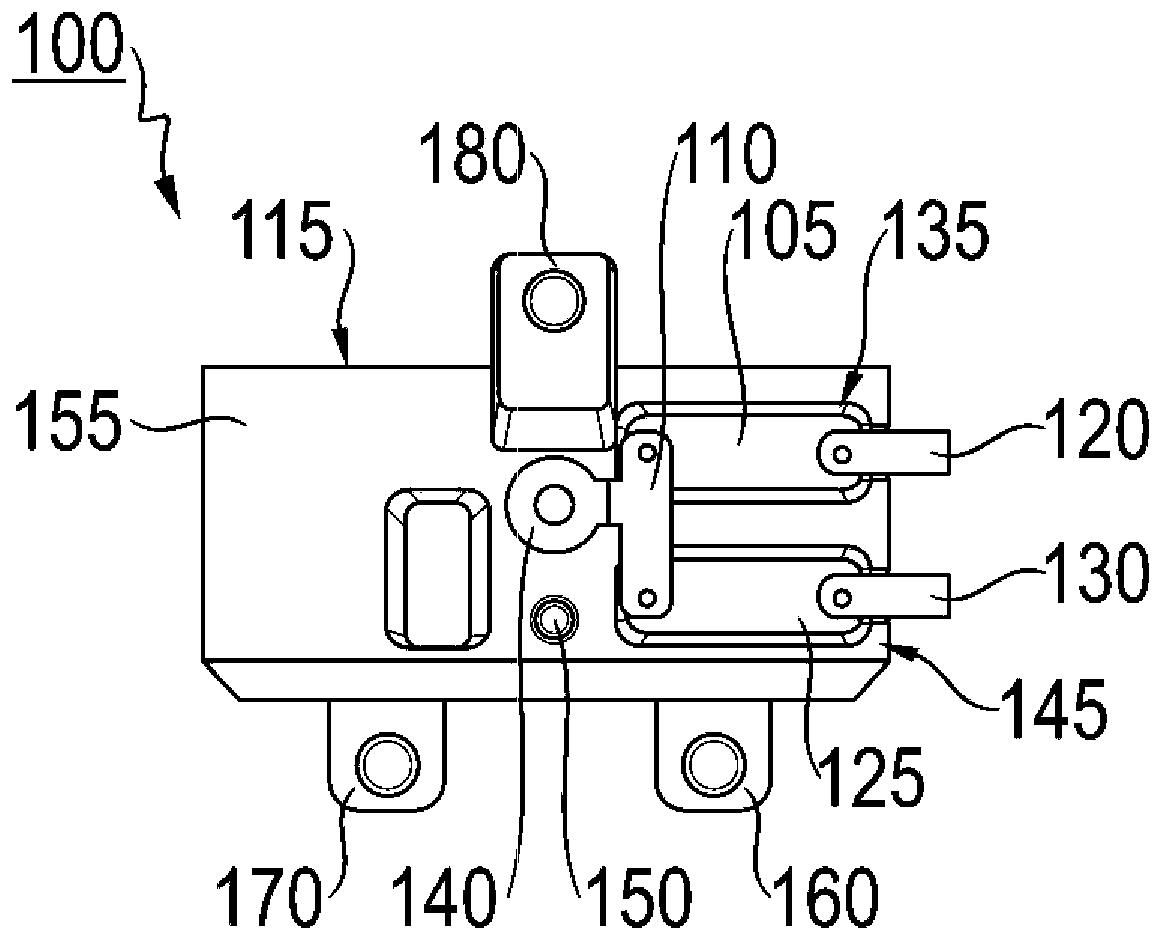
1 eine Darstellung eines Ausführungsbeispiels einer Kondensatoreinrichtung; -
2 eine Darstellung eines Ausführungsbeispiels einer Kondensatoreinrichtung; -
3 eine Darstellung eines Ausführungsbeispiels einer Kondensatoreinrichtung; -
4 eine Darstellung eines Ausführungsbeispiels einer Kondensatoreinrichtung; -
5 eine Darstellung eines Ausführungsbeispiels einer Kondensatorvorrichtung; -
6 eine Darstellung eines Ausführungsbeispiels einer Kondensatorvorrichtung; -
7 eine schematische Darstellung eines Ausführungsbeispiels einer Kondensatorvorrichtung; -
8 eine schematische Darstellung eines Ausführungsbeispiels einer Kondensatorvorrichtung; -
9 eine schematische Darstellung eines Ausführungsbeispiels einer Kondensatorvorrichtung; -
10 eine schematische Darstellung eines Ausführungsbeispiels einer Kondensatorvorrichtung; -
11 eine schematische Darstellung eines Ausführungsbeispiels einer Kondensatorvorrichtung; -
12 eine schematische Darstellung eines Ausführungsbeispiels einer Kondensatorvorrichtung; -
13 eine Draufsichtdarstellung eines Ausführungsbeispiels einer Kondensatoreinrichtung; -
14 eine Darstellung eines Ausführungsbeispiels einer Kondensatoreinrichtung; -
15 eine Explosionsdarstellung eines Ausführungsbeispiels einer Kondensatoreinrichtung; -
16 eine Darstellung eines Ausführungsbeispiels einer Kondensatoreinrichtung; -
17 eine schematische Darstellung eines Ausführungsbeispiels eines Kraftfahrzeugs; und -
18 ein Ablaufdiagramm eines Ausführungsbeispiels eines Verfahrens zum Herstellen einer Kondensatoreinrichtung.
-
1 a representation of an embodiment of a capacitor device; -
2 a representation of an embodiment of a capacitor device; -
3 a representation of an embodiment of a capacitor device; -
4 a representation of an embodiment of a capacitor device; -
5 a representation of an embodiment of a capacitor device; -
6 a representation of an embodiment of a capacitor device; -
7 a schematic representation of an embodiment of a capacitor device; -
8 a schematic representation of an embodiment of a capacitor device; -
9 a schematic representation of an embodiment of a capacitor device; -
10 a schematic representation of an embodiment of a capacitor device; -
11 a schematic representation of an embodiment of a capacitor device; -
12 a schematic representation of an embodiment of a capacitor device; -
13 a plan view of an embodiment of a capacitor device; -
14 a representation of an embodiment of a capacitor device; -
15 an exploded view of an embodiment of a capacitor device; -
16 a representation of an embodiment of a capacitor device; -
17 a schematic representation of an embodiment of a motor vehicle; and -
18 a flow chart of an embodiment of a method for producing a capacitor device.
In der nachfolgenden Beschreibung bevorzugter Ausführungsbeispiele der vorliegenden Erfindung werden für die in den verschiedenen Figuren dargestellten und ähnlich wirkenden Elemente gleiche oder ähnliche Bezugszeichen verwendet, wobei auf eine wiederholte Beschreibung dieser Elemente verzichtet wird.In the following description of preferred embodiments of the present invention, the same or similar reference numerals are used for the elements shown in the various figures and having a similar effect, whereby a repeated description of these elements is omitted.
Die Kondensatoreinrichtung 100 weist zumindest einen Kondensator 105, ein Gehäuse 115, eine erste Stromschiene 110 und eine zweite Stromschiene 120 auf. Gemäß einem Ausführungsbeispiel weist die Kondensatoreinrichtung 100 zusätzlich einen weiteren Kondensator 125 und eine dritte Stromschiene 130 auf.The
Das Gehäuse 115 weist lediglich beispielhaft eine rechteckige Form auf, wobei die Kondensatoren 105, 125 entlang einer Längserstreckung des Gehäuses 115 innerhalb des Gehäuses 115 angeordnet sind. Genauer gesagt formt das Gehäuse 115 beispielsweise zwei Aufnahmebereiche 135, 145 aus, wobei der Kondensator 105 innerhalb des Aufnahmebereichs 135 angeordnet ist und der weitere Kondensator 125 in dem weiteren Aufnahmebereich 145 angeordnet ist. Dabei sind die Aufnahmebereiche 135, 145 parallel zueinander entlang der Längserstreckung des Gehäuses 115 ausgeformt. Die Kondensatoren 105, 125 sind lediglich beispielhaft identisch ausgeformt und weisen eine rechteckige Form auf. Die Aufnahmebereiche 135, 145 sind ebenfalls rechteckig ausgeformt, um die Kondensatoren 105, 125 formschlüssig aufzunehmen. Auf diese Weise sind die Kondensatoren 105, 125 zuverlässig in dem Gehäuse 115 angeordnet. Die Kondensatoren 105, 125 können auch als Y-Kondensatoren bezeichnet werden.The
Die Stromschienen 110, 120, 130 sind ausgebildet, um die Kondensatoreinrichtung 100 elektrisch zu kontaktieren. Dazu ist der Kondensator 105 zwischen der erste Stromschiene 110 und der zweiten Stromschiene 120 elektrisch kontaktiert. Der weitere Kondensator 125 ist beispielsweise zwischen der ersten Stromschiene 110 und der dritten Stromschiene 130 elektrisch kontaktiert. Die Stromschienen 110, 120, 130 sind beispielsweise als Kontaktzungen ausgeformt. Dabei ist die erste Stromschiene 110 derart ausgeformt, das sie beide Kondensatoren 105, 125 kontaktiert. Genauer gesagt ist die erste Stromschiene 110 rechteckförmig ausgeformt, wobei die erste Stromschiene 110 eine Durchgangsöffnung 140 ausformt, die sich von einer Seitenwand der ersten Stromschiene 110 wegerstreckt. Die Durchgangsöffnung 140 ist beispielsweise ausgebildet, um ein Verbindungselement aufzunehmen, wie es beispielsweise in
Gemäß einem Ausführungsbeispiel weist die Kondensatoreinrichtung 100 ein Koppelelement 150 auf, das an dem Gehäuse 115 angeordnet ist. Das Koppelelement 150 ist beispielsweise ausgeformt, um die Kondensatoreinrichtung 100 mit einem Gegenkoppelelement eines benachbarten Zwischenkreiskondensators zu koppeln, wie es beispielsweise in der
Zusätzlich weist die Kondensatoreinrichtung 100 ein Gegenkoppelelement 160 auf, das ebenfalls an dem Gehäuse 115 angeordnet ist. Das Gegenkoppelelement 160 ist beispielsweise ausgeformt, um die Kondensatoreinrichtung 100 mit einem Koppelelement des benachbarten Zwischenkreiskondensators zu koppeln. Das Gegenkoppelelement 160 ist beispielsweise an einem Boden des Gehäuses 115 angeordnet. Gemäß einem Ausführungsbeispiel sind das Koppelelement 150 und das Gegenkoppelelement 160 an derselben Seite des Gehäuses 115 angeordnet. Dabei ist das Gegenkoppelelement 160 als ein Steg oder Haltebügel ausgeformt, der auf dem Boden des Gehäuses 115 aufsitzt und einen über einen Rand des Gehäuses 115 hinausragenden Überstand aufweist. Gemäß einem Ausführungsbeispiel weist das Gegenkoppelelement 160 im Bereich des Überstands eine Durchgangsöffnung auf, die einen Durchmesser aufweist, der zur Aufnahme eines Pins des Koppelements des benachbarten Zwischenkreiskondensators geeignet ist. Gemäß einem Ausführungsbeispiel entspricht eine Dicke des Stegs einer Länge des Pins.In addition, the
Das Koppelelement 150 und/oder das Gegenkoppelelement 160 sind ausgeformt, um die Kondensatoreinrichtung formschlüssig oder kraftschlüssig mit dem benachbarten Zwischenkreiskondensator zu koppeln.The
Gemäß einem Ausführungsbeispiel weist die Kondensatoreinrichtung 100 ein weiteres Gegenkoppelelement 170 auf, das benachbart zu dem Gegenkoppelelement 160 an dem Gehäuse 115, genauer gesagt an dem Boden des Gehäuses 115 angeordnet ist. Die Gegenkoppelelemente 160, 170 sind lediglich beispielhaft identisch ausgeformt. Das weitere Gegenkoppelelement 170 ist ausgeformt, um die Kondensatoreinrichtung 100 mit einem weiteren Koppelelement des benachbarten Zwischenkreiskondensators zu koppeln.According to one embodiment, the
Die Kondensatoreinrichtung 100 ist zudem ausgebildet, um mit einem zweiten Zwischenkreiskondensator zu koppeln, wie es beispielsweise in
In anderen Worten ausgedrückt werden die Kondensatoren 105, 125 eingesetzt, um hochfrequente Störsignale gegen Masse abzuleiten. Im Falle eines Umrichters werden diese im Betrieb durch das Schalten der Leistungshalbleiter hervorgerufen. Aus diesem Grund ist die Wirkung der Kondensatoren 105, 125 am größten, wenn diese möglichst nahe an den DC-Anschlüssen der Leistungshalbleiter platziert werden. Der hier vorgestellte Ansatz ermöglicht eine einfache Integration der Kondensatoren 105, 125 in eine Kondensatorvorrichtung, wie sie beispielsweise in
Das Gehäuse 115 ist schemenhaft dargestellt, wodurch unter anderem die Kondensatoren 105, 125 sichtbar sind, wobei das Gehäuse 115 beispielsweise ein Kunststoffmaterial aufweist und auch als Kunststoffhalter bezeichnet werden kann.The
Das Gehäuse 115 formt beispielsweise einen Schraubdom 400 aus. Genauer gesagt ist der Schraubdom 400 mittig an dem Boden 455 des Gehäuses 115 ausgeformt und ausgebildet, um mit der ersten Stromschiene 110 über ein Verbindungselement, das in
Das Gehäuse 115 ist gemäß dem hier gezeigten Ausführungsbeispiel in zwei Bereiche 410, 412 unterteilt. In dem ersten Bereich 410 sind die Kondensatoren 105, 125 mit den Stromschienen 110, 120, 130 angeordnet, in dem zweiten Bereich 412 ist der Schraubdom 400 ausgeformt.According to the embodiment shown here, the
Die Kondensatoreinrichtung 100 weist gemäß einem Ausführungsbeispiel ein weiteren Koppelelement 450 auf, das gegenüberliegend zu dem Gegenkoppelelement 160 an dem Boden 455 des Gehäuses 115 angeordnet ist und ausgebildet ist, um die Kondensatoreinrichtung 100 mit einem weiteren Gegenkoppelelement des weiteren benachbarten Zwischenkreiskondensators zu koppeln.According to one embodiment, the
Das Koppelelement 150 und das weitere Koppelelement 450 sind diagonal zueinander angeordnet und identisch ausgeformt, lediglich beispielhaft als Pins, die auch als Fixierungs-Pins bezeichnet werden können. Die Gegenkoppelelemente 160, 180 sind ebenfalls diagonal zueinander angeordnet und beispielhaft identisch ausgeformt, lediglich beispielhaft als Haltebügel zur Fixierung.The
Die Kondensatorvorrichtung 500 weist eine Kondensatoreinrichtung 100 und einen benachbarten Zwischenkreiskondensator 510 auf. Die Kondensatoreinrichtung 100 ähnelt oder entspricht dabei der Kondensatoreinrichtung aus einer der vorstehend beschriebenen Figuren. Gemäß einem Ausführungsbeispiel weist die Kondensatorvorrichtung 500 eine Mehrzahl von Zwischenkreiskondensatoren, hier lediglich beispielhaft vier Zwischenkreiskondensatoren 510, 520, 530, 540 auf. Gemäß einem Ausführungsbeispiel kann die Kondensatorvorrichtung 500 eine beliebige Anzahl an Zwischenkreiskondensatoren und Kondensatoreinrichtungen aufweisen.The
Der benachbarte Zwischenkreiskondensator 510 weist ein Gehäuse 515, eine erste Stromschiene 511 und eine zweite Stromschiene 512 auf. Zusätzlich weist der benachbarte Zwischenkreiskondensator 510 ein Gegenkoppelelement 518 auf, das an dem Gehäuse 515 angeordnet ist und in das Koppelelement 150 der Kondensatoreinrichtung 100 eingreift.The adjacent
Die Zwischenkreiskondensatoren 510, 520, 530, 540 sind lediglich beispielhaft identisch ausgeformt, sodass jeder Zwischenkreiskondensator 510, 520, 530, 540 ein Gehäuse 515, 525, 535, 545, sowie eine erste Stromschiene 511, 521, 531, 541 und eine zweite Stromschiene 512, 522, 532, 542 aufweist.The
Die Kondensatoreinrichtung 100 ist lediglich beispielhaft zwischen dem benachbarten Zwischenkreiskondensator 510 und dem zweiten Zwischenkreiskondensator 520 angeordnet. Der zweite Zwischenkreiskondensator 520 weist dazu beispielsweise ein Koppelelement 526 auf, das an dem Gehäuse 525 angeordnet ist und wobei das dritte Gegenkoppelelement 180 der Kondensatoreinrichtung 100 in das Koppelelement 526 des zweiten Zwischenkreiskondensators 520 eingreift. Auf diese Weise ist eine formschlüssige und kraftschlüssige Verbindung der Kondensatoreinrichtung 100 mit den Zwischenkreiskondensatoren 510, 520 möglich.The
Der zweite Zwischenkreiskondensator 520 weist zusätzlich ein Gegenkoppelelement 528 auf, das an dem Gehäuse 525 angeordnet ist und in ein Koppelelement 536 des dritten Zwischenkreiskondensators 530 eingreift. Der dritte Zwischenkreiskondensator 530 wiederrum weist ein Gegenkoppelelement 538 auf, das an dem Gehäuse 535 angeordnet ist und beispielsweise ausgebildet ist, um in ein Koppelelement eines weiteren Zwischenkreiskondensators einzugreifen, der hier nicht gezeigt ist. Alternativ ist es möglich, ein Befestigungselement, beispielsweise eine Schraube oder ein Bolzen, durch eine Durchgangsöffnung des Gegenkoppelelements 538 zu führen, um die Kondensatorvorrichtung 500 beispielsweise an einer Fahrzeugkomponente anzuordnen.The second
Der vierte Zwischenkreiskondensator 540 ist lediglich beispielhaft an dem benachbarten Zwischenkreiskondensator 510 angeordnet. Dazu greift ein Gegenkoppelelement 548 des vierten Zwischenkreiskondensators 540 in ein Koppelelement 516 des benachbarten Zwischenkreiskondensators 510. Der vierte Zwischenkreiskondensator 540 weist zusätzlich ein Koppelelement 546 auf, das an dem Gehäuse 545 des vierten Zwischenkreiskondensators 540 angeordnet ist und beispielsweise ausgebildet ist, um ein Gegenkoppelelement eines weiteren Zwischenkreiskondensators zu koppeln, der hier nicht gezeigt ist. Zusätzlich weist der vierte Zwischenkreiskondensator 540 weitere Gegenkoppelelemente 558, 568 auf, die an einer Unterseite des Gehäuses 545 angeordnet sind. Die weiteren Gegenkoppelelemente 558, 568 sind beispielsweise ausgebildet, um in Koppelelemente des weiteren Zwischenkreiskondensators einzugreifen, der hier nicht gezeigt ist. Alternativ sind die weiteren Gegenkoppelemente 558, 568 mittels Befestigungselementen, beispielsweise Schrauben oder Bolzen, an einem Trägerelement befestigbar.The fourth
In anderen Worten ausgedrückt zeigt
Dabei ist das Koppelelement der Kondensatoreinrichtung 100 mit dem Gegenkoppelelement 518 des benachbarten Zwischenkreiskondensators 510 gekoppelt. Zusätzlich ist das weitere Gegenkoppelement 170 der Kondensatoreinrichtung 100 mit einem Koppelelement des benachbarten Zwischenkreiskondensators 510 gekoppelt. Das dritte Gegenkoppelelement 180 der Kondensatoreinrichtung 100 ist mit dem Koppelelement des zweiten Zwischenkreiskondensators 520 gekoppelt. Ferner ist ein weiteres Koppelelement der Kondensatoreinrichtung 100 mit einem weiteren Gegenkoppelement 628 des zweiten Zwischenkreiskondensators 520 gekoppelt.The coupling element of the
Der dritte Zwischenkreiskondensator 530 ist mittels eines weiteren Gegenkoppelelements 638 mit einem Koppelelement des zweiten Zwischenkreiskondensators 520 gekoppelt. Der dritte Zwischenkreiskondensator 530 weist zusätzlich ein weiteres Koppelelement 636 auf, das beispielsweise ausgebildet ist, um mit einem weiteren Gegenkoppelement eines weiteren Zwischenkreiskondensators zu koppeln, der hier nicht gezeigt ist.The third
Der vierte Zwischenkreiskondensator 540 ist mittels eines weiteren Koppelements mit dem weiteren Gegenkoppelelement 568 des benachbarten Zwischenkreiskondensators 510 gekoppelt.The fourth
In anderen Worten ausgedrückt zeigt
Die Kondensatoreinrichtung 100 lässt sich je nach Bauraum und Anzahl der Zwischenkreiskondensatoren 510, 520, 530, 540, die auch als Wickelelemente bezeichnet werden können, auch an allen anderen möglichen Positionen einfügen. Somit ist die Anbindung der Kondensatoreinrichtung 100 sehr flexibel.Depending on the installation space and the number of
Gemäß dem hier gezeigten Ausführungsbeispiel ist die Kondensatoreinrichtung 100 zwischen dem benachbarten Zwischenkreiskondensator 510 und dem vierten Zwischenkreiskondensator 540 angeordnet.According to the embodiment shown here, the
Gemäß dem hier gezeigten Ausführungsbeispiel ist die Kondensatoreinrichtung 100 zwischen dem dritten Zwischenkreiskondensator 530 und dem zweiten Zwischenkreiskondensator 520 angeordnet.According to the embodiment shown here, the
Gemäß dem hier gezeigten Ausführungsbeispiel ist die Kondensatoreinrichtung 100 benachbart zu dem dritten Zwischenkreiskondensator 530 angeordnet.According to the embodiment shown here, the
Die Kondensatorvorrichtung 500 weist eine ungerade Anzahl von Zwischenkreiskondensatoren 510, 520, 530 auf, hier lediglich beispielhaft drei Zwischenkreiskondensatoren 510, 520, 530. Zudem weist die Kondensatorvorrichtung 500 zusätzlich zu der Kondensatoreinrichtung 100 eine weitere Kondensatoreinrichtung 1100 auf.The
Dabei ist die Kondensatoreinrichtung 100 lediglich beispielhaft benachbart zu dem zweiten Zwischenkreiskondensator 520 angeordnet und die weitere Kondensatoreinrichtung 1100 benachbart zu dem dritten Zwischenkreiskondensator 530 angeordnet. Der benachbarte Zwischenkreiskondensator 510 ist demnach lediglich beispielhaft zwischen dem zweiten Zwischenkreiskondensator 520 und dem dritten Zwischenkreiskondensator 530 angeordnet.The
Die Kondensatoreinrichtungen 100, 1100 weisen lediglich beispielhaft je nur einen Kondensator oder eine geringe Kapazität auf und sind daher beispielsweise schmaler ausgeformt als die Zwischenkreiskondensatoren 510, 520, 530.The
In anderen Worten ausgedrückt zeigt
Gemäß einem Ausführungsbeispiel ist der benachbarte Zwischenkreiskondensator 510 zwischen den Kondensatoreinrichtungen 100, 1100 angeordnet. In anderen Worten ausgedrückt ist die Kondensatoreinrichtung 100 zwischen dem benachbarten Zwischenkreiskondensator 510 und dem zweiten Zwischenkreiskondensator 520 angeordnet. Die weitere Kondensatoreinrichtung 1100 ist zwischen dem benachbarten Zwischenkreiskondensator 510 und dem dritten Zwischenkreiskondensator 530 angeordnet.According to one embodiment, the adjacent
Die Kondensatoreinrichtung 100 ist lediglich beispielhaft zwischen dem benachbarten Zwischenkreiskondensator 510 und dem zweiten Zwischenkreiskondensator 520 angeordnet.The
Dabei ist die zweite Stromschiene 120 lediglich beispielhaft mit einer weiteren Stromschiene 1300, beispielsweise von einer Leiterplatte, elektrisch kontaktiert. Die dritte Stromschiene 130 ist mit einer zusätzlichen Stromschiene 1310 elektrisch kontaktiert. Der Bereich 1305 der Kontaktierung ist beispielsweise mittels gestrichelter Linien dargestellt.The
In anderen Worten ausgedrückt zeigt
Das Gehäuse 115 formt beispielsweise einen Schraubdom 400 aus. Die erste Stromschiene 110 liegt beispielsweise an einer Oberseite des Schraubdoms 400 an, sodass die erste Stromschiene 110 über ein Verbindungselement 1400, beispielsweise eine Schraube, mit dem Schraubdom 400 verbunden ist. Somit ist der Schraubdom als ein Masseanschluss ausgebildet.The
Gemäß einem Ausführungsbeispiel erstreckt sich der Schraubdom 400 von dem Boden 455 des Gehäuses 115 in Richtung des Deckels 155 des Gehäuses 115. Eine Durchgangsöffnung 1410 in dem Gehäuse 115 ist ausgebildet, um das Verbindungselement 1400 aufzunehmen, sodass das Verbindungselement 1400 die erste Stromschiene 110 mit dem Schraubdom 400 verbinden kann.According to one embodiment, the
In anderen Worten ausgedrückt zeigt
Die Anordnung der Kondensatoren 105, 125 in dem Gehäuse 115 bzw. in den Aufnahmebereichen 135, 145 sind beispielhaft mittels je einem Pfeil dargestellt. Gemäß einem Ausführungsbeispiel weist jeder Kondensator 105, 125 je zwei Pins 1505, 1515, 1525, 1535 auf, auf die die Stromschienen gesteckt werden, wie es beispielhaft in
In anderen Worten ausgedrückt zeigt
In anderen Worten ausgedrückt zeigt
Elektrische Energie zum Betreiben der elektrischen Maschine 1725 wird von einer Energieversorgungseinrichtung, hier dem elektrischen Energiespeicher 1710 bereitgestellt. Der elektrische Energiespeicher 1710 ist ausgebildet, um Gleichstrom bereitzustellen, der unter Verwendung eines Stromrichters 1720 des elektrischen Achsantriebs 1715 in einen Wechselstrom, beispielsweise einen dreiphasigen Wechselstrom, gewandelt und der elektrischen Maschine 1725 bereitgestellt wird. Eine von der elektrischen Maschine 1725 angetriebene Welle ist direkt oder unter Verwendung der Getriebeeinrichtung 1730 mit zumindest einem Rad 1705 des Kraftfahrzeugs 1700 gekoppelt. Somit kann das Kraftfahrzeug 1700 unter Verwendung der elektrischen Maschine 1725 fortbewegt werden. Gemäß einem Ausführungsbeispiel umfasst der elektrische Achsantrieb 1715 ein Gehäuse, in dem der Stromrichter 1720, die elektrische Maschine 1725 und die Getriebeeinrichtung 1730 angeordnet sind.Electrical energy for operating the
Gemäß einem Ausführungsbeispiel umfasst der Stromrichter 1720 zumindest eine Kondensatorvorrichtung 500, wie sie anhand der vorangegangenen Figuren beschrieben ist. Beispielsweise ist die Kondensatorvorrichtung 500 in einem Zwischenkreis des Stromrichters 1720 angeordnet.According to one embodiment, the
Das Verfahren 1800 umfasst einen Schritt 1805 des Bereitstellens des zumindest einen Kondensators, des Gehäuses, der ersten Stromschiene und der zweiten Stromschiene. Zusätzlich umfasst das Verfahren 1800 einen Schritt 1810 des Anordnens des zumindest einen Kondensators in dem Gehäuse und einen Schritt 1815 des Anbringens der ersten Stromschiene und der zweiten Stromschiene an dem zumindest einen Kondensator, um die Kondensatoreinrichtung herzustellen.The
Die beschriebenen und in den Figuren gezeigten Ausführungsbeispiele sind nur beispielhaft gewählt. Unterschiedliche Ausführungsbeispiele können vollständig oder in Bezug auf einzelne Merkmale miteinander kombiniert werden. Auch kann ein Ausführungsbeispiel durch Merkmale eines weiteren Ausführungsbeispiels ergänzt werden.The embodiments described and shown in the figures are selected only as examples. Different embodiments can be combined with each other completely or with regard to individual features. An embodiment can also be supplemented by features of another embodiment.
Ferner können erfindungsgemäße Verfahrensschritte wiederholt sowie in einer anderen als in der beschriebenen Reihenfolge ausgeführt werden.Furthermore, method steps according to the invention can be repeated and carried out in a different order than that described.
Umfasst ein Ausführungsbeispiel eine „und/oder“ Verknüpfung zwischen einem ersten Merkmal und einem zweiten Merkmal, so kann dies so gelesen werden, dass das Ausführungsbeispiel gemäß einer Ausführungsform sowohl das erste Merkmal als auch das zweite Merkmal und gemäß einer weiteren Ausführungsform entweder nur das erste Merkmal oder nur das zweite Merkmal aufweist.If an embodiment includes an “and/or” connection between a first feature and a second feature, this can be read as meaning that the embodiment according to one embodiment has both the first feature and the second feature and according to a further embodiment has either only the first feature or only the second feature.
Bezugszeichenreference sign
- 100100
- Kondensatoreinrichtungcondenser device
- 105105
- Kondensatorcapacitor
- 110110
- erste Stromschienefirst power rail
- 115115
- GehäuseHousing
- 120120
- zweite Stromschienesecond power rail
- 125125
- weiterer Kondensatoradditional capacitor
- 130130
- dritte Stromschienethird power rail
- 135135
- Aufnahmebereichrecording area
- 140140
- Durchgangsöffnungpassage opening
- 145145
- weiterer Aufnahmebereichadditional recording area
- 150150
- Koppelelementcoupling element
- 155155
- DeckelLid
- 160160
- Gegenkoppelelementcounter-coupling element
- 170170
- weiteres Gegenkoppelementadditional negative feedback element
- 180180
- drittes Gegenkoppelelementthird negative feedback element
- 400400
- Schraubdomscrew dome
- 410410
- erster Bereichfirst area
- 412412
- zweiter Bereichsecond area
- 450450
- weiteres Koppelelementadditional coupling element
- 455455
- BodenFloor
- 500500
- Kondensatorvorrichtungcapacitor device
- 510510
- benachbarter Zwischenkreiskondensatoradjacent intermediate circuit capacitor
- 511511
- erste Stromschiene des benachbarten Zwischenkreiskondensatorsfirst busbar of the adjacent intermediate circuit capacitor
- 512512
- zweite Stromschiene des benachbarten Zwischenkreiskondensatorssecond busbar of the adjacent intermediate circuit capacitor
- 515515
- Gehäuse des benachbarten Zwischenkreiskondensatorshousing of the adjacent intermediate circuit capacitor
- 516516
- Koppelelement des benachbarten Zwischenkreiskondensatorscoupling element of the adjacent intermediate circuit capacitor
- 518518
- Gegenkoppelelement des benachbarten Zwischenkreiskondensatorsnegative feedback element of the adjacent intermediate circuit capacitor
- 520520
- zweiter Zwischenkreiskondensatorsecond intermediate circuit capacitor
- 521521
- erste Stromschiene des zweiten Zwischenkreiskondensatorsfirst busbar of the second intermediate circuit capacitor
- 522522
- zweite Stromschiene des zweiten Zwischenkreiskondensatorssecond busbar of the second intermediate circuit capacitor
- 525525
- Gehäuse des zweiten Zwischenkreiskondensatorshousing of the second intermediate circuit capacitor
- 526526
- Koppelelement des zweiten Zwischenkreiskondensatorscoupling element of the second intermediate circuit capacitor
- 528528
- Gegenkoppelelement des zweiten Zwischenkreiskondensatorsnegative feedback element of the second intermediate circuit capacitor
- 530530
- dritter Zwischenkreiskondensatorthird intermediate circuit capacitor
- 531531
- erste Stromschiene des dritten Zwischenkreiskondensatorsfirst busbar of the third intermediate circuit capacitor
- 532532
- zweite Stromschiene des dritten Zwischenkreiskondensatorssecond busbar of the third intermediate circuit capacitor
- 535535
- Gehäuse des dritten Zwischenkreiskondensatorshousing of the third intermediate circuit capacitor
- 536536
- Koppelelement des dritten Zwischenkreiskondensatorscoupling element of the third intermediate circuit capacitor
- 538538
- Gegenkoppelelement des dritten Zwischenkreiskondensatorsnegative feedback element of the third intermediate circuit capacitor
- 540540
- vierter Zwischenkreiskondensatorfourth intermediate circuit capacitor
- 541541
- erste Stromschiene des vierten Zwischenkreiskondensatorsfirst busbar of the fourth intermediate circuit capacitor
- 542542
- zweite Stromschiene des vierten Zwischenkreiskondensatorssecond busbar of the fourth intermediate circuit capacitor
- 545545
- Gehäuse des vierten Zwischenkreiskondensatorshousing of the fourth intermediate circuit capacitor
- 546546
- Koppelelement des vierten Zwischenkreiskondensatorscoupling element of the fourth intermediate circuit capacitor
- 548548
- Gegenkoppelelement des vierten Zwischenkreiskondensatorsnegative feedback element of the fourth intermediate circuit capacitor
- 558558
- weiteres zweites Gegenkoppelelement des vierten Zwischenkreiskondensa- torsfurther second negative feedback element of the fourth intermediate circuit capacitor
- 568568
- weiteres Gegenkoppelelement des vierten Zwischenkreiskondensatorsadditional negative feedback element of the fourth intermediate circuit capacitor
- 618618
- weiteres Gegenkoppelelement des benachbarten Zwischenkreiskondensa-torsadditional negative feedback element of the adjacent intermediate circuit capacitor
- 628628
- weiteres Gegenkoppelelement des zweiten Zwischenkreiskondensatorsadditional negative feedback element of the second intermediate circuit capacitor
- 636636
- weiteres Koppelelement des dritten Zwischenkreiskondensatorsadditional coupling element of the third intermediate circuit capacitor
- 638638
- weiteres Gegenkoppelelement des dritten Zwischenkreiskondensatorsadditional negative feedback element of the third intermediate circuit capacitor
- 11001100
- weitere Kondensatoreinrichtungadditional capacitor device
- 13001300
- weitere Stromschieneadditional power rail
- 13051305
- Bereich der Kontaktierungarea of contact
- 13101310
- zusätzliche Stromschieneadditional power rail
- 14001400
- Verbindungselementconnecting element
- 14101410
- Durchgangsöffnung in dem Gehäusethrough hole in the housing
- 15051505
- Pin des Kondensatorspin of the capacitor
- 15151515
- weiterer Pin des Kondensatorsanother pin of the capacitor
- 15251525
- Pin des weiteren Kondensatorspin of the other capacitor
- 15351535
- weiterer Pin des weiteren Kondensatorsanother pin of the other capacitor
- 17001700
- Kraftfahrzeugmotor vehicle
- 17051705
- Radwheel
- 17101710
- elektrischer Energiespeicherelectrical energy storage
- 17151715
- elektrischer Achsantriebelectric axle drive
- 17201720
- Stromrichterpower converter
- 17251725
- elektrische Maschineelectric machine
- 17301730
- Getriebeeinrichtungtransmission device
- 18001800
- Verfahren zum Herstellen einer KondensatoreinrichtungMethod for producing a capacitor device
- 18051805
- Schritt des Bereitstellensstep of deployment
- 18101810
- Schritt des Anordnensstep of arranging
- 18151815
- Schritt des Anbringensstep of installation
Claims (15)
Priority Applications (1)
| Application Number | Priority Date | Filing Date | Title |
|---|---|---|---|
| DE102023206574.6A DE102023206574A1 (en) | 2023-07-11 | 2023-07-11 | Capacitor device, capacitor apparatus, motor vehicle and method for producing a capacitor device |
Applications Claiming Priority (1)
| Application Number | Priority Date | Filing Date | Title |
|---|---|---|---|
| DE102023206574.6A DE102023206574A1 (en) | 2023-07-11 | 2023-07-11 | Capacitor device, capacitor apparatus, motor vehicle and method for producing a capacitor device |
Publications (1)
| Publication Number | Publication Date |
|---|---|
| DE102023206574A1 true DE102023206574A1 (en) | 2025-01-16 |
Family
ID=93930786
Family Applications (1)
| Application Number | Title | Priority Date | Filing Date |
|---|---|---|---|
| DE102023206574.6A Pending DE102023206574A1 (en) | 2023-07-11 | 2023-07-11 | Capacitor device, capacitor apparatus, motor vehicle and method for producing a capacitor device |
Country Status (1)
| Country | Link |
|---|---|
| DE (1) | DE102023206574A1 (en) |
Citations (3)
| Publication number | Priority date | Publication date | Assignee | Title |
|---|---|---|---|---|
| DE102013203614A1 (en) * | 2013-03-04 | 2014-08-07 | Siemens Aktiengesellschaft | Capacitor unit for use in intermediate circuit of frequency converter of e.g. electric vehicle, has screening and power capacitor arranged in housing, where terminals of screening capacitors are grounded over conducting part of housing |
| DE102020105826A1 (en) * | 2019-03-15 | 2020-09-17 | Tdk Corporation | ELECTRONIC DEVICE |
| DE102022201333A1 (en) * | 2022-02-09 | 2023-08-10 | Zf Friedrichshafen Ag | Intermediate circuit capacitor with optimized heat dissipation, power converter with such an intermediate circuit capacitor |
-
2023
- 2023-07-11 DE DE102023206574.6A patent/DE102023206574A1/en active Pending
Patent Citations (3)
| Publication number | Priority date | Publication date | Assignee | Title |
|---|---|---|---|---|
| DE102013203614A1 (en) * | 2013-03-04 | 2014-08-07 | Siemens Aktiengesellschaft | Capacitor unit for use in intermediate circuit of frequency converter of e.g. electric vehicle, has screening and power capacitor arranged in housing, where terminals of screening capacitors are grounded over conducting part of housing |
| DE102020105826A1 (en) * | 2019-03-15 | 2020-09-17 | Tdk Corporation | ELECTRONIC DEVICE |
| DE102022201333A1 (en) * | 2022-02-09 | 2023-08-10 | Zf Friedrichshafen Ag | Intermediate circuit capacitor with optimized heat dissipation, power converter with such an intermediate circuit capacitor |
Similar Documents
| Publication | Publication Date | Title |
|---|---|---|
| DE102016103338B4 (en) | Structure for maintaining the orientation of a support with respect to a case | |
| WO2018091021A1 (en) | Busbar comprising a metal-sheet stack and method for producing a busbar | |
| DE202017007694U1 (en) | Voltage converter for supplying power to an electrical machine for motor vehicles | |
| DE102022201614A1 (en) | Interface device for a vehicle electric powertrain, electric powertrain for a vehicle, vehicle and method of manufacturing an interface device | |
| EP4373228A1 (en) | Inverter and drive train of a motor vehicle | |
| DE102020107131B4 (en) | Power electronics unit and motor vehicle | |
| DE102022132448A1 (en) | EMC filter device in space-saving design; control electronics and electrical machine | |
| DE102023206574A1 (en) | Capacitor device, capacitor apparatus, motor vehicle and method for producing a capacitor device | |
| DE102017127895A1 (en) | Inverter for electric motor | |
| DE102022207432B4 (en) | Inverter for converting a first voltage into a second voltage and method for producing an inverter | |
| DE102022207437A1 (en) | DC link capacitor for a motor vehicle, capacitor device, motor vehicle and method for producing a DC link capacitor | |
| DE102020118425A1 (en) | Arrangement with a first and a second power semiconductor module and with a DC voltage busbar | |
| DE9218583U1 (en) | Self-assembling bus | |
| EP0291765B1 (en) | Carbon brush holder arrangement | |
| EP4246783A1 (en) | Electric motor | |
| DE102021208789A1 (en) | Intermediate circuit capacitor for an electric drive of an electric vehicle or a hybrid vehicle, inverter with such an intermediate circuit capacitor | |
| DE102024127006B3 (en) | Power semiconductor module with a first and a second DC load connection | |
| WO2020151966A1 (en) | Electronic module and drive | |
| DE102021102020A1 (en) | Low inductance capacitor module; as well as inverter electronics and power electronics unit | |
| DE102023203771B3 (en) | Inverter for a separately excited synchronous machine and method for producing an inverter | |
| DE102023126438B3 (en) | Method for producing a circuit arrangement for an electrical machine, power semiconductor module for a circuit arrangement and corresponding circuit arrangement | |
| DE102020111528A1 (en) | Power electronic arrangement with a multi-phase power semiconductor module | |
| EP4500669B1 (en) | Electric motor | |
| DE102023126067B4 (en) | Three-level power semiconductor module and arrangement thereof | |
| DE102024207208A1 (en) | Fastening element for connecting a component to a housing, in particular a housing of an electronic module, system consisting of at least one printed circuit board and fastening element, as well as electronic module |
Legal Events
| Date | Code | Title | Description |
|---|---|---|---|
| R012 | Request for examination validly filed | ||
| R016 | Response to examination communication |