DE102023204829A1 - operating device for a motor vehicle, motor vehicle - Google Patents
operating device for a motor vehicle, motor vehicle Download PDFInfo
- Publication number
- DE102023204829A1 DE102023204829A1 DE102023204829.9A DE102023204829A DE102023204829A1 DE 102023204829 A1 DE102023204829 A1 DE 102023204829A1 DE 102023204829 A DE102023204829 A DE 102023204829A DE 102023204829 A1 DE102023204829 A1 DE 102023204829A1
- Authority
- DE
- Germany
- Prior art keywords
- housing part
- actuating device
- actuating
- gear members
- gear
- Prior art date
- Legal status (The legal status is an assumption and is not a legal conclusion. Google has not performed a legal analysis and makes no representation as to the accuracy of the status listed.)
- Pending
Links
Images

Classifications
-
- B—PERFORMING OPERATIONS; TRANSPORTING
- B60—VEHICLES IN GENERAL
- B60T—VEHICLE BRAKE CONTROL SYSTEMS OR PARTS THEREOF; BRAKE CONTROL SYSTEMS OR PARTS THEREOF, IN GENERAL; ARRANGEMENT OF BRAKING ELEMENTS ON VEHICLES IN GENERAL; PORTABLE DEVICES FOR PREVENTING UNWANTED MOVEMENT OF VEHICLES; VEHICLE MODIFICATIONS TO FACILITATE COOLING OF BRAKES
- B60T7/00—Brake-action initiating means
- B60T7/02—Brake-action initiating means for personal initiation
- B60T7/04—Brake-action initiating means for personal initiation foot actuated
- B60T7/042—Brake-action initiating means for personal initiation foot actuated by electrical means, e.g. using travel or force sensors
-
- B—PERFORMING OPERATIONS; TRANSPORTING
- B60—VEHICLES IN GENERAL
- B60T—VEHICLE BRAKE CONTROL SYSTEMS OR PARTS THEREOF; BRAKE CONTROL SYSTEMS OR PARTS THEREOF, IN GENERAL; ARRANGEMENT OF BRAKING ELEMENTS ON VEHICLES IN GENERAL; PORTABLE DEVICES FOR PREVENTING UNWANTED MOVEMENT OF VEHICLES; VEHICLE MODIFICATIONS TO FACILITATE COOLING OF BRAKES
- B60T13/00—Transmitting braking action from initiating means to ultimate brake actuator with power assistance or drive; Brake systems incorporating such transmitting means, e.g. air-pressure brake systems
- B60T13/74—Transmitting braking action from initiating means to ultimate brake actuator with power assistance or drive; Brake systems incorporating such transmitting means, e.g. air-pressure brake systems with electrical assistance or drive
-
- B—PERFORMING OPERATIONS; TRANSPORTING
- B60—VEHICLES IN GENERAL
- B60T—VEHICLE BRAKE CONTROL SYSTEMS OR PARTS THEREOF; BRAKE CONTROL SYSTEMS OR PARTS THEREOF, IN GENERAL; ARRANGEMENT OF BRAKING ELEMENTS ON VEHICLES IN GENERAL; PORTABLE DEVICES FOR PREVENTING UNWANTED MOVEMENT OF VEHICLES; VEHICLE MODIFICATIONS TO FACILITATE COOLING OF BRAKES
- B60T7/00—Brake-action initiating means
- B60T7/02—Brake-action initiating means for personal initiation
- B60T7/04—Brake-action initiating means for personal initiation foot actuated
- B60T7/06—Disposition of pedal
-
- B—PERFORMING OPERATIONS; TRANSPORTING
- B60—VEHICLES IN GENERAL
- B60T—VEHICLE BRAKE CONTROL SYSTEMS OR PARTS THEREOF; BRAKE CONTROL SYSTEMS OR PARTS THEREOF, IN GENERAL; ARRANGEMENT OF BRAKING ELEMENTS ON VEHICLES IN GENERAL; PORTABLE DEVICES FOR PREVENTING UNWANTED MOVEMENT OF VEHICLES; VEHICLE MODIFICATIONS TO FACILITATE COOLING OF BRAKES
- B60T7/00—Brake-action initiating means
- B60T7/02—Brake-action initiating means for personal initiation
- B60T7/08—Brake-action initiating means for personal initiation hand actuated
- B60T7/085—Brake-action initiating means for personal initiation hand actuated by electrical means, e.g. travel, force sensors
-
- B—PERFORMING OPERATIONS; TRANSPORTING
- B60—VEHICLES IN GENERAL
- B60T—VEHICLE BRAKE CONTROL SYSTEMS OR PARTS THEREOF; BRAKE CONTROL SYSTEMS OR PARTS THEREOF, IN GENERAL; ARRANGEMENT OF BRAKING ELEMENTS ON VEHICLES IN GENERAL; PORTABLE DEVICES FOR PREVENTING UNWANTED MOVEMENT OF VEHICLES; VEHICLE MODIFICATIONS TO FACILITATE COOLING OF BRAKES
- B60T8/00—Arrangements for adjusting wheel-braking force to meet varying vehicular or ground-surface conditions, e.g. limiting or varying distribution of braking force
- B60T8/32—Arrangements for adjusting wheel-braking force to meet varying vehicular or ground-surface conditions, e.g. limiting or varying distribution of braking force responsive to a speed condition, e.g. acceleration or deceleration
- B60T8/321—Arrangements for adjusting wheel-braking force to meet varying vehicular or ground-surface conditions, e.g. limiting or varying distribution of braking force responsive to a speed condition, e.g. acceleration or deceleration deceleration
- B60T8/3255—Systems in which the braking action is dependent on brake pedal data
-
- B—PERFORMING OPERATIONS; TRANSPORTING
- B60—VEHICLES IN GENERAL
- B60T—VEHICLE BRAKE CONTROL SYSTEMS OR PARTS THEREOF; BRAKE CONTROL SYSTEMS OR PARTS THEREOF, IN GENERAL; ARRANGEMENT OF BRAKING ELEMENTS ON VEHICLES IN GENERAL; PORTABLE DEVICES FOR PREVENTING UNWANTED MOVEMENT OF VEHICLES; VEHICLE MODIFICATIONS TO FACILITATE COOLING OF BRAKES
- B60T8/00—Arrangements for adjusting wheel-braking force to meet varying vehicular or ground-surface conditions, e.g. limiting or varying distribution of braking force
- B60T8/32—Arrangements for adjusting wheel-braking force to meet varying vehicular or ground-surface conditions, e.g. limiting or varying distribution of braking force responsive to a speed condition, e.g. acceleration or deceleration
- B60T8/34—Arrangements for adjusting wheel-braking force to meet varying vehicular or ground-surface conditions, e.g. limiting or varying distribution of braking force responsive to a speed condition, e.g. acceleration or deceleration having a fluid pressure regulator responsive to a speed condition
- B60T8/40—Arrangements for adjusting wheel-braking force to meet varying vehicular or ground-surface conditions, e.g. limiting or varying distribution of braking force responsive to a speed condition, e.g. acceleration or deceleration having a fluid pressure regulator responsive to a speed condition comprising an additional fluid circuit including fluid pressurising means for modifying the pressure of the braking fluid, e.g. including wheel driven pumps for detecting a speed condition, or pumps which are controlled by means independent of the braking system
- B60T8/4072—Systems in which a driver input signal is used as a control signal for the additional fluid circuit which is normally used for braking
- B60T8/4081—Systems with stroke simulating devices for driver input
-
- B—PERFORMING OPERATIONS; TRANSPORTING
- B60—VEHICLES IN GENERAL
- B60T—VEHICLE BRAKE CONTROL SYSTEMS OR PARTS THEREOF; BRAKE CONTROL SYSTEMS OR PARTS THEREOF, IN GENERAL; ARRANGEMENT OF BRAKING ELEMENTS ON VEHICLES IN GENERAL; PORTABLE DEVICES FOR PREVENTING UNWANTED MOVEMENT OF VEHICLES; VEHICLE MODIFICATIONS TO FACILITATE COOLING OF BRAKES
- B60T8/00—Arrangements for adjusting wheel-braking force to meet varying vehicular or ground-surface conditions, e.g. limiting or varying distribution of braking force
- B60T8/32—Arrangements for adjusting wheel-braking force to meet varying vehicular or ground-surface conditions, e.g. limiting or varying distribution of braking force responsive to a speed condition, e.g. acceleration or deceleration
- B60T8/34—Arrangements for adjusting wheel-braking force to meet varying vehicular or ground-surface conditions, e.g. limiting or varying distribution of braking force responsive to a speed condition, e.g. acceleration or deceleration having a fluid pressure regulator responsive to a speed condition
- B60T8/40—Arrangements for adjusting wheel-braking force to meet varying vehicular or ground-surface conditions, e.g. limiting or varying distribution of braking force responsive to a speed condition, e.g. acceleration or deceleration having a fluid pressure regulator responsive to a speed condition comprising an additional fluid circuit including fluid pressurising means for modifying the pressure of the braking fluid, e.g. including wheel driven pumps for detecting a speed condition, or pumps which are controlled by means independent of the braking system
- B60T8/4072—Systems in which a driver input signal is used as a control signal for the additional fluid circuit which is normally used for braking
- B60T8/4081—Systems with stroke simulating devices for driver input
- B60T8/4086—Systems with stroke simulating devices for driver input the stroke simulating device being connected to, or integrated in the driver input device
-
- F—MECHANICAL ENGINEERING; LIGHTING; HEATING; WEAPONS; BLASTING
- F16—ENGINEERING ELEMENTS AND UNITS; GENERAL MEASURES FOR PRODUCING AND MAINTAINING EFFECTIVE FUNCTIONING OF MACHINES OR INSTALLATIONS; THERMAL INSULATION IN GENERAL
- F16D—COUPLINGS FOR TRANSMITTING ROTATION; CLUTCHES; BRAKES
- F16D65/00—Parts or details
- F16D65/78—Features relating to cooling
- F16D65/84—Features relating to cooling for disc brakes
- F16D65/847—Features relating to cooling for disc brakes with open cooling system, e.g. cooled by air
-
- G—PHYSICS
- G05—CONTROLLING; REGULATING
- G05G—CONTROL DEVICES OR SYSTEMS INSOFAR AS CHARACTERISED BY MECHANICAL FEATURES ONLY
- G05G1/00—Controlling members, e.g. knobs or handles; Assemblies or arrangements thereof; Indicating position of controlling members
- G05G1/02—Controlling members for hand actuation by linear movement, e.g. push buttons
-
- G—PHYSICS
- G05—CONTROLLING; REGULATING
- G05G—CONTROL DEVICES OR SYSTEMS INSOFAR AS CHARACTERISED BY MECHANICAL FEATURES ONLY
- G05G1/00—Controlling members, e.g. knobs or handles; Assemblies or arrangements thereof; Indicating position of controlling members
- G05G1/04—Controlling members for hand actuation by pivoting movement, e.g. levers
-
- G—PHYSICS
- G05—CONTROLLING; REGULATING
- G05G—CONTROL DEVICES OR SYSTEMS INSOFAR AS CHARACTERISED BY MECHANICAL FEATURES ONLY
- G05G1/00—Controlling members, e.g. knobs or handles; Assemblies or arrangements thereof; Indicating position of controlling members
- G05G1/30—Controlling members actuated by foot
- G05G1/38—Controlling members actuated by foot comprising means to continuously detect pedal position
-
- G—PHYSICS
- G05—CONTROLLING; REGULATING
- G05G—CONTROL DEVICES OR SYSTEMS INSOFAR AS CHARACTERISED BY MECHANICAL FEATURES ONLY
- G05G1/00—Controlling members, e.g. knobs or handles; Assemblies or arrangements thereof; Indicating position of controlling members
- G05G1/30—Controlling members actuated by foot
- G05G1/42—Controlling members actuated by foot non-pivoting, e.g. sliding
-
- G—PHYSICS
- G05—CONTROLLING; REGULATING
- G05G—CONTROL DEVICES OR SYSTEMS INSOFAR AS CHARACTERISED BY MECHANICAL FEATURES ONLY
- G05G1/00—Controlling members, e.g. knobs or handles; Assemblies or arrangements thereof; Indicating position of controlling members
- G05G1/30—Controlling members actuated by foot
- G05G1/44—Controlling members actuated by foot pivoting
-
- G—PHYSICS
- G05—CONTROLLING; REGULATING
- G05G—CONTROL DEVICES OR SYSTEMS INSOFAR AS CHARACTERISED BY MECHANICAL FEATURES ONLY
- G05G5/00—Means for preventing, limiting or returning the movements of parts of a control mechanism, e.g. locking controlling member
- G05G5/03—Means for enhancing the operator's awareness of arrival of the controlling member at a command or datum position; Providing feel, e.g. means for creating a counterforce
-
- B—PERFORMING OPERATIONS; TRANSPORTING
- B60—VEHICLES IN GENERAL
- B60T—VEHICLE BRAKE CONTROL SYSTEMS OR PARTS THEREOF; BRAKE CONTROL SYSTEMS OR PARTS THEREOF, IN GENERAL; ARRANGEMENT OF BRAKING ELEMENTS ON VEHICLES IN GENERAL; PORTABLE DEVICES FOR PREVENTING UNWANTED MOVEMENT OF VEHICLES; VEHICLE MODIFICATIONS TO FACILITATE COOLING OF BRAKES
- B60T2220/00—Monitoring, detecting driver behaviour; Signalling thereof; Counteracting thereof
- B60T2220/04—Pedal travel sensor, stroke sensor; Sensing brake request
-
- B—PERFORMING OPERATIONS; TRANSPORTING
- B60—VEHICLES IN GENERAL
- B60T—VEHICLE BRAKE CONTROL SYSTEMS OR PARTS THEREOF; BRAKE CONTROL SYSTEMS OR PARTS THEREOF, IN GENERAL; ARRANGEMENT OF BRAKING ELEMENTS ON VEHICLES IN GENERAL; PORTABLE DEVICES FOR PREVENTING UNWANTED MOVEMENT OF VEHICLES; VEHICLE MODIFICATIONS TO FACILITATE COOLING OF BRAKES
- B60T2270/00—Further aspects of brake control systems not otherwise provided for
- B60T2270/82—Brake-by-Wire, EHB
Landscapes
- Engineering & Computer Science (AREA)
- Physics & Mathematics (AREA)
- Mechanical Engineering (AREA)
- Transportation (AREA)
- General Physics & Mathematics (AREA)
- Automation & Control Theory (AREA)
- Fluid Mechanics (AREA)
- General Engineering & Computer Science (AREA)
- Gear Transmission (AREA)
- Mechanical Control Devices (AREA)
Abstract
Die Erfindung betrifft eine Betätigungsvorrichtung (1) für ein Kraftfahrzeug, insbesondere zum Vorgeben eines Brems- und/oder Beschleunigungswunsches, mit einem ersten und einem zweiten Gehäuseteil (2,3), wobei das erste Gehäuseteil (2) auf einer von dem zweiten Gehäuseteil (3) abgewandten Oberseite (4) eine Betätigungsfläche (6) aufweist oder wobei auf der Oberseite (4) eine Abdeckung (5) mit der Betätigungsfläche (6) angeordnet ist, und wobei das erste Gehäuseteil (2) durch ein Parallelogrammgetriebe (7) an dem zweiten Gehäuseteil (3) verschiebbar gelagert ist.

Description
Die Erfindung betrifft eine Betätigungsvorrichtung für ein Kraftfahrzeug, insbesondere zum Vorgeben eines Brems- und/oder Beschleunigungswunsches.The invention relates to an actuating device for a motor vehicle, in particular for specifying a braking and/or acceleration request.
Außerdem betrifft die Erfindung ein Kraftfahrzeug mit zumindest einer derartigen Betätigungsvorrichtung.Furthermore, the invention relates to a motor vehicle with at least one such actuating device.
Stand der TechnikState of the art
Aus dem Stand der Technik ist es bekannt, eine Betätigung einer von einem Fahrer betätigbaren Betätigungsvorrichtung für ein Kraftfahrzeug durch einen der Betätigungsvorrichtung zugeordneten Sensor zu erfassen. Betätigt der Fahrer die Betätigungsvorrichtung, so wird in Abhängigkeit davon insbesondere ein Brems- oder Beschleunigungswunsch des Fahrers erkannt. Beispielsweise sind Bremsanlagen mit elektromechanischen Bremskraftverstärkern bekannt, die zusammen mit einem Fahrzeugassistenzsystem, insbesondere einem elektronischen Stabilitätsprogramm (ESP), ein redundantes „Brake-by-Wire“-System bilden, bei dem keine mechanische Verbindung von der Betätigungsvorrichtung zu der Bremsanlage vorliegt. Ein Bremswunsch wird beispielsweise in Abhängigkeit von einer Betätigung der Betätigungsvorrichtung an einen elektromechanischen Aktuator weitergeleitet, der dazu ausgebildet ist, einen Druckaufbau in der Bremsanlage auszuführen. Analog sind Betätigungsvorrichtungen für Antriebseinheiten, insbesondere mit Verbrennungskraftmaschinen und/oder elektrischen Maschinen, von Kraftfahrzeugen bekannt, die Teil eines „Drive-by-Wire“-Systems ohne mechanische Verbindung zu der Antriebseinheit sind. Ein Beschleunigungswunsch wird beispielsweise in Abhängigkeit von einer Betätigung der Betätigungsvorrichtung erkannt und an die Antriebseinheit weitergeleitet. Aufgrund der fehlenden mechanischen Kopplung der Betätigungsvorrichtungen zu Bremsanlage und/oder Antriebseinheit ist es möglich, derartige Betätigungsvorrichtungen wegfrei oder mit zumindest nur geringem Hub von wenigen Millimetern auszubilden. Zum Erfassen der Betätigung ist der Einsatz verschiedener Messmethoden bekannt. Beispielsweise offenbaren die Offenlegungsschriften
Offenbarung der Erfindungdisclosure of the invention
Die erfindungsgemäße Betätigungsvorrichtung mit den Merkmalen des Anspruchs 1 weist ein erstes und ein zweites Gehäuseteil auf, wobei das erste Gehäuseteil auf einer von dem zweiten Gehäuseteil abgewandten Oberseite eine Betätigungsfläche aufweist oder wobei auf der Oberseite eine Abdeckung mit der Betätigungsfläche angeordnet ist, und wobei das erste Gehäuseteil durch ein Parallelogrammgetriebe an dem zweiten Gehäuseteil verschiebbar gelagert ist. Dadurch ist eine besonders vorteilhafte Lagerung einer wie eingangs beschriebenen Betätigungsvorrichtung mit geringem Hub gewährleistet. Besonders bevorzugt ist in dem zweiten Gehäuseteil zumindest eine elektrische Komponente einer Sensoranordnung zum Erfassen einer Betätigung der Betätigungsvorrichtung, insbesondere zum Erfassen einer auf die Betätigungsfläche ausgeübten Betätigungskraft und/oder eines Betätigungswegs, angeordnet. Vorzugsweise ist das Parallelogrammgetriebe in Quererstreckung und/oder Längserstreckung zumindest annähernd mittig an dem ersten und/oder zweiten Gehäuseteil angeordnet. Insbesondere weist das Parallelogrammgetriebe den gleichen Abstand zu jeweils zwei einander gegenüberliegenden Außenkanten des ersten und/oder zweiten Gehäuseteils auf. Besonders bevorzugt ist zumindest einer der Gehäuseteile in Quererstreckung und/oder Längserstreckung zumindest annähernd spiegelsymmetrisch ausgebildet. Die Betätigungsvorrichtung weist dadurch eine besonders vorteilhaft einfache Geometrie auf. Das zweite Gehäuseteil ist insbesondere dazu ausgebildet, in einem Bodenbereich des Kraftfahrzeugs, vor einem Fahrersitz, befestigt zu werden. Vorzugsweise erlaubt das Parallelogrammgetriebe einen Hub von weniger als 10 mm, insbesondere weniger als 5 mm, des ersten Gehäuseteils relativ zu dem zweiten Gehäuseteil.The actuating device according to the invention with the features of claim 1 has a first and a second housing part, wherein the first housing part has an actuating surface on an upper side facing away from the second housing part or wherein a cover with the actuating surface is arranged on the upper side, and wherein the first housing part is slidably mounted on the second housing part by a parallelogram gear. This ensures a particularly advantageous mounting of an actuating device with a small stroke as described at the beginning. Particularly preferably, at least one electrical component of a sensor arrangement for detecting an actuation of the actuating device, in particular for detecting an actuating force exerted on the actuating surface and/or an actuating path, is arranged in the second housing part. The parallelogram gear is preferably arranged at least approximately centrally on the first and/or second housing part in the transverse extension and/or longitudinal extension. In particular, the parallelogram gear has the same distance to two opposing outer edges of the first and/or second housing part. Particularly preferably, at least one of the housing parts is designed to be at least approximately mirror-symmetrical in the transverse and/or longitudinal extent. The actuating device therefore has a particularly advantageously simple geometry. The second housing part is designed in particular to be fastened in a floor area of the motor vehicle, in front of a driver's seat. The parallelogram gear preferably allows a stroke of less than 10 mm, in particular less than 5 mm, of the first housing part relative to the second housing part.
Gemäß einer bevorzugten Weiterbildung der Erfindung ist vorgesehen, dass das Parallelogrammgetriebe zumindest zwei gleich lange, voneinander beabstandete und stets zueinander parallel ausgerichtete Getriebeglieder aufweist, die einendig an dem ersten Gehäuseteil und anderendig an dem zweiten Gehäuseteil verschwenkbar gelagert sind, sodass das erste Gehäuseteil bei einer Verlagerung der Getriebeglieder parallel zu einer Bodenebene des zweiten Gehäuseteils ausgerichtet bleibt. Durch die entsprechend ausgebildeten und angeordneten Getriebeglieder ist vorteilhaft sichergestellt, dass das erste Gehäuseteil exakt an dem zweiten Gehäuseteil verschiebbar geführt ist. Insbesondere weisen die Getriebeglieder jeweils einendig eine Lagerstelle auf, die beispielsweise ein Wälzlagerelement oder Gleitlagerelement umfasst, sodass die Getriebeglieder vorteilhaft verschleißarm gelagert sind.According to a preferred development of the invention, the parallelogram gear has at least two gear members of equal length, spaced apart from one another and always aligned parallel to one another, which are pivotably mounted at one end on the first housing part and at the other end on the second housing part, so that the first housing part remains aligned parallel to a floor plane of the second housing part when the gear members are displaced. The appropriately designed and arranged gear members advantageously ensure that the first housing part is guided exactly on the second housing part so that it can be displaced. In particular, the gear members each have a bearing point at one end, which comprises, for example, a roller bearing element or plain bearing element, so that the gear members are advantageously mounted in a low-wear manner.
Besonders bevorzugt ist vorgesehen, dass das Parallelogrammgetriebe für jedes der Getriebeglieder jeweils eine erste, dem ersten Gehäuseteil zugeordnete, Schwenkachse und eine zweite, dem zweiten Gehäuseteil zugeordnete, Schwenkachse aufweist, wobei die Schwenkachsen jeweils zumindest annähernd parallel zu einer Kante der Betätigungsfläche und/oder zumindest eines der Gehäuseteile verlaufen und/oder quer zu einer Längserstreckung der Betätigungsfläche und/oder zumindest eines der Gehäuseteile ausgerichtet sind. Durch eine derartige Zuordnung und Ausrichtung der Schwenkachsen ist vorteilhaft sichergestellt, dass die Betätigungsvorrichtung besonders intuitiv betätigbar ist. Vorzugsweise sind die Schwenkachsen bei bestimmungsgemäßem Gebrauch quer zu einer Längsrichtung der Betätigungsfläche angeordnet.It is particularly preferred that the parallelogram transmission has a first pivot axis associated with the first housing part and a second pivot axis associated with the second housing part for each of the transmission elements, wherein the pivot axes are each at least approximately parallel to an edge of the actuating surface and/or at least one of the housing parts and/or are aligned transversely to a longitudinal extension of the actuating surface and/or at least one of the housing parts. Such an assignment and alignment of the pivot axes advantageously ensures that the actuating device can be operated particularly intuitively. Preferably, the pivot axes are arranged transversely to a longitudinal direction of the actuating surface when used as intended.
Gemäß einer bevorzugten Weiterbildung der Erfindung ist vorgesehen, dass zwei derartige Parallelogrammgetriebe jeweils an einer gegenüberliegenden Längsseite der Betätigungsvorrichtung angeordnet sind, wobei jeweils zwei der Getriebeglieder um eine gemeinsame erste und zweite der Schwenkachsen drehbar sind. Durch das Vorsehen zwei derartiger Parallelogrammgetriebe ist vorteilhaft sichergestellt, dass eine Stabilität des Parallelogrammgetriebes weiter verbessert ist. Insbesondere funktioniert es auch dann zuverlässig, wenn die Betätigungseinrichtung außermittig betätigt wird.According to a preferred development of the invention, two such parallelogram gears are each arranged on an opposite longitudinal side of the actuating device, with two of the gear members being rotatable about a common first and second of the pivot axes. By providing two such parallelogram gears, it is advantageously ensured that the stability of the parallelogram gear is further improved. In particular, it also functions reliably when the actuating device is actuated off-center.
Besonders bevorzugt ist vorgesehen, dass jedes der Getriebeglieder jeweils einendig an einer anderen Ecke des ersten und des zweiten Gehäuseteiles gelenkig gelagert ist. Durch eine entsprechende Lagerung an den Ecken ergibt sich der Vorteil, dass eine Verlagerbarkeit des ersten Gehäuseteils unabhängig von einer Betätigungsposition jederzeit gewährleistet ist.It is particularly preferred that each of the gear members is articulated at one end to a different corner of the first and second housing parts. Appropriate mounting at the corners provides the advantage that the first housing part can be moved at any time, regardless of the operating position.
Gemäß einer bevorzugten Weiterbildung der Erfindung ist vorgesehen, dass das Parallelogrammgetriebe eine zwischen den beiden Gehäuseteilen angeordnete und mit dem ersten Gehäuseteil verbundene Lagerplatte aufweist. Durch eine derartige Lagerplatte ist vorteilhaft sichergestellt, dass eine Betätigung mittels des Parallelogrammgetriebes flächig übertragen wird.According to a preferred development of the invention, it is provided that the parallelogram gear has a bearing plate arranged between the two housing parts and connected to the first housing part. Such a bearing plate advantageously ensures that an actuation by means of the parallelogram gear is transmitted over a large area.
Besonders bevorzugt ist vorgesehen, dass die Getriebeglieder jeweils durch einen elastisch verformbaren ersten Abschnitt einstückig mit der Lagerplatte, insbesondere um eine der ersten Schwenkachsen, verschwenkbar verbunden sind, und dass die Getriebeglieder jeweils an oder beabstandet von einem von der Lagerplatte abgewandten Ende einen elastisch verformbaren zweiten Abschnitt aufweisen und mit dem zweiten Gehäuseteil, insbesondere um eine der zweiten Schwenkachsen, verschwenkbar verbunden sind. Dadurch ergibt sich der Vorteil, dass das Parallelogrammgetriebe besonders einfach zu fertigen und zu montieren ist, weil es letztlich nur ein Bauteil aus Lagerplatte mit Getriebegliedern aufweist. Das Bauteil ist insbesondere aus Federstahl gefertigt.It is particularly preferred that the gear members are each integrally connected to the bearing plate by an elastically deformable first section, in particular pivotable about one of the first pivot axes, and that the gear members each have an elastically deformable second section at or spaced from an end facing away from the bearing plate and are pivotably connected to the second housing part, in particular pivotable about one of the second pivot axes. This results in the advantage that the parallelogram gear is particularly easy to manufacture and assemble because it ultimately has only one component made of a bearing plate with gear members. The component is made in particular from spring steel.
Gemäß einer bevorzugten Weiterbildung der Erfindung ist vorgesehen, dass die Lagerplatte und/oder zumindest eines der Getriebeglieder außerhalb der elastisch verformbaren Abschnitte Materialverdickungen aufweist. Durch derartige Materialverdickungen ist vorteilhaft sichergestellt, dass die elastische Verformung und damit die Verschwenkung nur an den Schwenkachsen stattfindet. Insbesondere ist so verhindert, dass die Lagerplatte und/oder die Getriebeglieder sich ungewollt verformen oder verbiegen.According to a preferred development of the invention, it is provided that the bearing plate and/or at least one of the gear members has material thickenings outside the elastically deformable sections. Such material thickenings advantageously ensure that the elastic deformation and thus the pivoting only takes place on the pivot axes. In particular, this prevents the bearing plate and/or the gear members from deforming or bending unintentionally.
Besonders bevorzugt ist vorgesehen, dass die Lagerplatte mit dem ersten Gehäuseteil und/oder zumindest eines der Getriebeglieder mit dem zweiten Gehäuseteil kraftschlüssig, formschlüssig und/oder stoffschlüssig verbunden, insbesondere verschraubt, ist. Durch die formschlüssige, kraftschlüssige und/oder stoffschlüssige Verbindung im Unterschied zu einer einteiligen Ausbildung ist eine besonders vorteilhafte Möglichkeit zum flexiblen Herstellen der Lagerplatte und/oder der Getriebeglieder, insbesondere ihrer Geometrie, geschaffen. Alternativ ist die Lagerplatte mit dem ersten Gehäuseteil und/oder zumindest eines der Getriebeglieder mit dem zweiten Gehäuseteil einteilig ausgebildet. Durch die einteilige Ausbildung ergibt sich der Vorteil, dass das jeweilige Bauteil ohne einen zusätzlichen Schritt beim Zusammenfügen der Betätigungsvorrichtung hergestellt ist.It is particularly preferred that the bearing plate is connected to the first housing part and/or at least one of the gear members is connected to the second housing part in a force-fitting, positive-locking and/or material-locking manner, in particular screwed. The positive-locking, force-fitting and/or material-locking connection, in contrast to a one-piece design, creates a particularly advantageous possibility for the flexible manufacture of the bearing plate and/or the gear members, in particular their geometry. Alternatively, the bearing plate is formed in one piece with the first housing part and/or at least one of the gear members is formed in one piece with the second housing part. The one-piece design has the advantage that the respective component is manufactured without an additional step when assembling the actuating device.
Gemäß einer bevorzugten Weiterbildung der Erfindung ist vorgesehen, dass zwischen den Gehäuseteilen zumindest ein Federelement, insbesondere Schraubenfeder, als Rückstellfeder angeordnet ist. Durch das Federelement ist vorteilhaft sichergestellt, dass das erste Gehäuseteil in einem unbetätigten Zustand in eine vorgegebene Ausgangslage zurückkehrt. Insbesondere sind zumindest zwei Federelemente diametral gegenüberliegend, beispielsweise jeweils einer anderen Ecke zumindest eines der Gehäuseteile zugeordnet, angeordnet. Durch zumindest zwei diametral gegenüberliegende Federelemente ist eine besonders vorteilhaft gleichmäßige Rückstellung erreicht. Vorzugsweise ist eine Vielzahl von Federelementen, insbesondere vier Federelemente gleichmäßig verteilt angeordnet, wobei jeweils zwei der Federelemente einander diametral gegenüberliegend angeordnet sind, und/oder wobei die Federelemente gleichmäßig verteilt angeordnet sind, insbesondere jeweils einer anderen Ecke zumindest eines der Gehäuseteile zugeordnet sind.According to a preferred development of the invention, at least one spring element, in particular a helical spring, is arranged as a return spring between the housing parts. The spring element advantageously ensures that the first housing part returns to a predetermined starting position in an unactuated state. In particular, at least two spring elements are arranged diametrically opposite one another, for example each assigned to a different corner of at least one of the housing parts. A particularly advantageous uniform return is achieved by at least two diametrically opposed spring elements. Preferably, a plurality of spring elements, in particular four spring elements, are arranged evenly distributed, with two of the spring elements being arranged diametrically opposite one another, and/or with the spring elements being arranged evenly distributed, in particular each assigned to a different corner of at least one of the housing parts.
Besonders bevorzugt ist vorgesehen, dass in einem Bodenbereich des zweiten Gehäuseteils zumindest eine elektrische Komponente einer Sensoranordnung zum Erfassen einer auf die Betätigungsfläche ausgeübten Betätigungskraft und/oder eines Betätigungswegs angeordnet ist. Durch eine derartige Sensoranordnung ist eine besonders vorteilhafte Möglichkeit zum Erfassen eines Beschleunigungs- und/oder Bremswunsches geschaffen.It is particularly preferred that at least one electrical component of a sensor arrangement for detecting an actuating force exerted on the actuating surface and/or an actuating path is arranged in a bottom region of the second housing part. Such a sensor arrangement provides a particularly advantageous possibility for detecting an acceleration and/or braking request.
Gemäß einer bevorzugten Weiterbildung der Erfindung ist vorgesehen, dass in einem Bodenbereich des zweiten Gehäuseteils zumindest eine Beleuchtungseinrichtung, insbesondere Leuchtdiode, angeordnet ist. Durch die Beleuchtungseinrichtung ist eine besonders vorteilhafte Möglichkeit zur optischen Rückmeldung über eine Betätigung der Betätigungsvorrichtung an einen Benutzer geschaffen. Vorzugsweise ist die Beleuchtungseinrichtung dazu ausgebildet, gemeinsam mit einer Ambientebeleuchtung des Kraftfahrzeugs angesteuert zu werden. Beispielsweise wird die Beleuchtungseinrichtung beim Einsteigen und/oder Aussteigen des Fahrers angeschaltet, und/oder beim Fahren abgeschaltet. Alternativ wird eine Leuchtintensität oder Leuchtfarbe der Beleuchtungseinrichtung in Abhängigkeit von einer auf die Betätigungsfläche ausgeübten Betätigungskraft und/oder eines Betätigungswegs festgelegt. Insbesondere sind Brems- und Beschleunigungswunsch unterschiedliche Leuchtfarben zugeordnet.According to a preferred development of the invention, at least one lighting device, in particular a light-emitting diode, is arranged in a base area of the second housing part. The lighting device creates a particularly advantageous possibility for optical feedback to a user about an actuation of the actuating device. The lighting device is preferably designed to be controlled together with the ambient lighting of the motor vehicle. For example, the lighting device is switched on when the driver gets in and/or gets out, and/or switched off when driving. Alternatively, a light intensity or light color of the lighting device is determined depending on an actuation force exerted on the actuation surface and/or an actuation path. In particular, different light colors are assigned to braking and acceleration requests.
Besonders bevorzugt ist vorgesehen, dass die Komponente und die Beleuchtungseinrichtung auf einer gemeinsamen Leiterplatte angeordnet sind. Durch die Anordnung auf einer gemeinsamen Leiterplatte ergibt sich der Vorteil, dass die elektrische Kontaktierung ohne zusätzliche elektrische Leitungen sichergestellt ist. Die Leiterplatte mit der Komponente und der Beleuchtungseinrichtung ist vorteilhaft als vorgefertigte Einheit in das zweite Gehäuseteil einsetzbar.It is particularly preferred that the component and the lighting device are arranged on a common circuit board. The arrangement on a common circuit board has the advantage that electrical contact is ensured without additional electrical lines. The circuit board with the component and the lighting device can advantageously be inserted into the second housing part as a prefabricated unit.
Gemäß einer bevorzugten Weiterbildung der Erfindung ist vorgesehen, dass in den Gehäuseteilen ein Lichtleitelement für die Beleuchtungseinrichtung angeordnet ist, das sich von der Beleuchtungseinrichtung zu einer Öffnung in der Betätigungsfläche erstreckt. Durch das Lichtleitelement ist vorteilhaft sichergestellt, dass ein von der Beleuchtungseinrichtung ausgehender Leuchtstrahl auf der Betätigungsfläche sicher erkennbar ist.According to a preferred development of the invention, a light-guiding element for the lighting device is arranged in the housing parts, which extends from the lighting device to an opening in the actuating surface. The light-guiding element advantageously ensures that a light beam emanating from the lighting device can be reliably recognized on the actuating surface.
Das erfindungsgemäße Kraftfahrzeug mit den Merkmalen des Anspruchs 15 zeichnet sich durch zumindest eine erfindungsgemäße Betätigungsvorrichtung aus. Auch daraus ergeben sich die bereits genannten Vorteile.The motor vehicle according to the invention with the features of
Weitere bevorzugte Merkmale und Merkmalskombinationen ergeben sich aus dem zuvor Beschriebenen sowie aus den Ansprüchen. Im Folgenden wird die Erfindung anhand der Zeichnungen näher erläutert. Dazu zeigen
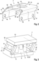
-
1 eine vorteilhafte Betätigungsvorrichtung, -
2 ein erstes Ausführungsbeispiel eines Parallelogrammgetriebes der Betätigungsvorrichtung, und -
3 ein zweites Ausführungsbeispiel des Parallelogrammgetriebes.
-
1 an advantageous actuating device, -
2 a first embodiment of a parallelogram transmission of the actuating device, and -
3 a second embodiment of the parallelogram transmission.
Die Betätigungsvorrichtung 1 weist ein erstes Gehäuseteil 2 und ein zweites Gehäuseteil 3 auf. Um das Innenleben der Betätigungseinrichtung 1 darstellen zu können, ist das zweite Gehäuseteil 3 angeschnitten dargestellt. Das erste Gehäuseteil 2 weist vorliegend auf einer von dem zweiten Gehäuseteil 3 abgewandten Oberseite 4 eine Abdeckung 5 mit einer Betätigungsfläche 6 auf. Alternativ weist das erste Gehäuseteil 2 die Betätigungsfläche 6 direkt auf der Oberseite 4 auf, insbesondere ist es einstückig mit dieser ausgebildet. Vorliegend sind sowohl die beiden Gehäuseteile 2, 3 als auch die Abdeckung 5 in Quererstreckung zumindest annähernd spiegelsymmetrisch ausgebildet.The actuating device 1 has a
Das erste Gehäuseteil 2 ist durch ein Parallelogrammgetriebe 7 an dem zweiten Gehäuseteil 3 verschiebbar gelagert. Für das Parallelogrammgetriebe 7 sind das in der
Beiden Ausführungsbeispiel ist gemeinsam, dass das Parallelogrammgetriebe 7 jeweils zumindest zwei gleich lange, voneinander beabstandete und stets zueinander parallel ausgerichtete Getriebeglieder 8 aufweist, die einendig an dem ersten Gehäuseteil 2 und anderendig an dem zweiten Gehäuseteil 3 verschwenkbar gelagert sind, sodass das erste Gehäuseteil 2 bei einer Verlagerung der Getriebeglieder 8 parallel zu einer Bodenebene 9 des zweiten Gehäuseteils 3 ausgerichtet bleibt.What both embodiments have in common is that the
Das Parallelogrammgetriebe 7 weist außerdem jeweils für jedes der Getriebeglieder 8 jeweils eine erste, dem ersten Gehäuseteil 2 zugeordnete, Schwenkachse 10 und eine zweite, dem zweiten Gehäuseteil 3 zugeordnete, Schwenkachse 11 auf. Die Schwenkachsen 10,11 verlaufen jeweils parallel zueinander, zu einer Kante 12 der Betätigungsfläche 6 sowie zu entsprechenden Außenkanten der Gehäuseteile 2, 3. Anders ausgedrückt sind die Schwenkachsen 10,11 jeweils quer zu einer Längserstreckung der Betätigungsfläche 6 sowie der Gehäuseteile 2, 3 ausgerichtet.The
Das Parallelogrammgetriebe 7 weist eine zwischen den beiden Gehäuseteilen 2, 3 angeordnete und mit dem ersten Gehäuseteil 2 verbundene Lagerplatte 13 auf. Die Lagerplatte 13 ist mit dem ersten Gehäuseteil 2 und/oder zumindest eines der Getriebeglieder 8 mit dem zweiten Gehäuseteil 3 kraftschlüssig, formschlüssig und/oder stoffschlüssig verbunden. Beispielsweise sind die Getriebeglieder 8, wie in der
In dem in den
Dabei weisen die Leiterplatte 13 sowie die Getriebeglieder 8 jeweils zwischen beziehungsweise außerhalb der elastisch verformbaren Abschnitte 15, 16 Materialverdickungen 19 auf, um sicherzustellen, dass die Verformung ausschließlich im Bereich der Abschnitte 15, 16 stattfindet.The
In dem in der
Vorliegend ist jedes der Getriebeglieder 8 dabei jeweils einendig an einer anderen Ecke des ersten und des zweiten Gehäuseteiles 2, 3 oder des zweiten Gehäuseteiles 3 und der Lagerplatte 13 gelenkig gelagert oder zumindest jeweils einer anderen Ecke zugeordnet.In the present case, each of the
In dem Bodenbereich 9 des zweiten Gehäuseteils 3 ist vorzugsweise zumindest eine elektrische Komponente 20 einer Sensoranordnung 21 zum Erfassen einer auf die Betätigungsfläche ausgeübten Betätigungskraft und/oder eines Betätigungswegs angeordnet. In der
Weiter ist in den Gehäuseteilen 2, 3 noch ein Lichtleitelement 24 für die Beleuchtungseinrichtung 19 angeordnet, das sich von der Beleuchtungseinrichtung 22 durch die Gehäuseteile 2, 3 hindurch zu einer Öffnung 25 in der Lagerplatte 13 und zu einer Öffnung 26 in der Betätigungsfläche 6 erstreckt. Die Beleuchtungseinrichtung 22 ist als Leuchtdiode insbesondere monochrom ausgebildet oder weist eine RGB-Ansteuerung auf.Furthermore, a light-guiding
Außerdem ist zwischen den Gehäuseteilen 2, 3 zumindest ein Federelement 27, beispielsweise als Schraubenfeder ausgebildet, als Rückstellfeder angeordnet. Insbesondere sind mehrere derartige Federelemente 27 zwischen den Gehäuseteilen 2, 3 angeordnet. In der
ZITATE ENTHALTEN IN DER BESCHREIBUNGQUOTES INCLUDED IN THE DESCRIPTION
Diese Liste der vom Anmelder aufgeführten Dokumente wurde automatisiert erzeugt und ist ausschließlich zur besseren Information des Lesers aufgenommen. Die Liste ist nicht Bestandteil der deutschen Patent- bzw. Gebrauchsmusteranmeldung. Das DPMA übernimmt keinerlei Haftung für etwaige Fehler oder Auslassungen.This list of documents listed by the applicant was generated automatically and is included solely for the better information of the reader. The list is not part of the German patent or utility model application. The DPMA accepts no liability for any errors or omissions.
Zitierte PatentliteraturCited patent literature
-
DE 10 2017 119 392 A1 [0003]
DE 10 2017 119 392 A1 [0003] - DE 102 39 913 A1 [0003]DE 102 39 913 A1 [0003]
- DE 103 12 547 A1 [0003]DE 103 12 547 A1 [0003]
Claims (15)
Priority Applications (2)
| Application Number | Priority Date | Filing Date | Title |
|---|---|---|---|
| DE102023204829.9A DE102023204829A1 (en) | 2023-05-24 | 2023-05-24 | operating device for a motor vehicle, motor vehicle |
| CN202410629516.6A CN119018117A (en) | 2023-05-24 | 2024-05-21 | Control device for motor vehicle, motor vehicle |
Applications Claiming Priority (1)
| Application Number | Priority Date | Filing Date | Title |
|---|---|---|---|
| DE102023204829.9A DE102023204829A1 (en) | 2023-05-24 | 2023-05-24 | operating device for a motor vehicle, motor vehicle |
Publications (1)
| Publication Number | Publication Date |
|---|---|
| DE102023204829A1 true DE102023204829A1 (en) | 2024-11-28 |
Family
ID=93381716
Family Applications (1)
| Application Number | Title | Priority Date | Filing Date |
|---|---|---|---|
| DE102023204829.9A Pending DE102023204829A1 (en) | 2023-05-24 | 2023-05-24 | operating device for a motor vehicle, motor vehicle |
Country Status (2)
| Country | Link |
|---|---|
| CN (1) | CN119018117A (en) |
| DE (1) | DE102023204829A1 (en) |
Citations (8)
| Publication number | Priority date | Publication date | Assignee | Title |
|---|---|---|---|---|
| DE3427416A1 (en) * | 1984-07-25 | 1986-02-06 | Messerschmitt-Bölkow-Blohm GmbH, 8012 Ottobrunn | Actuating device with an operating means to be actuated by means of angular movements of the foot |
| DE19811268A1 (en) * | 1998-03-11 | 1999-09-16 | Helke Lob | Foot-operated operating device for controlling automobile acceleration or braking |
| DE10239913A1 (en) | 2002-08-30 | 2004-03-18 | Audi Ag | Actuating means for influencing a system for braking, coupling or driving a motor vehicle |
| DE10312547A1 (en) | 2003-03-21 | 2004-10-14 | Audi Ag | Device for accelerating or decelerating a motor vehicle |
| US7017442B2 (en) * | 2000-06-16 | 2006-03-28 | Edscha Ag | Parking brake |
| JP2007257391A (en) * | 2006-03-24 | 2007-10-04 | Denso Corp | Pedal device |
| EP3020897A1 (en) * | 2014-11-12 | 2016-05-18 | Illinois Tool Works Inc. | Push button device with push actuation with improved kinematics for application in a vehicle |
| DE102017119392A1 (en) | 2016-08-30 | 2018-03-01 | GM Global Technology Operations LLC | BRAKE-BY-WIRE SYSTEM |
-
2023
- 2023-05-24 DE DE102023204829.9A patent/DE102023204829A1/en active Pending
-
2024
- 2024-05-21 CN CN202410629516.6A patent/CN119018117A/en active Pending
Patent Citations (8)
| Publication number | Priority date | Publication date | Assignee | Title |
|---|---|---|---|---|
| DE3427416A1 (en) * | 1984-07-25 | 1986-02-06 | Messerschmitt-Bölkow-Blohm GmbH, 8012 Ottobrunn | Actuating device with an operating means to be actuated by means of angular movements of the foot |
| DE19811268A1 (en) * | 1998-03-11 | 1999-09-16 | Helke Lob | Foot-operated operating device for controlling automobile acceleration or braking |
| US7017442B2 (en) * | 2000-06-16 | 2006-03-28 | Edscha Ag | Parking brake |
| DE10239913A1 (en) | 2002-08-30 | 2004-03-18 | Audi Ag | Actuating means for influencing a system for braking, coupling or driving a motor vehicle |
| DE10312547A1 (en) | 2003-03-21 | 2004-10-14 | Audi Ag | Device for accelerating or decelerating a motor vehicle |
| JP2007257391A (en) * | 2006-03-24 | 2007-10-04 | Denso Corp | Pedal device |
| EP3020897A1 (en) * | 2014-11-12 | 2016-05-18 | Illinois Tool Works Inc. | Push button device with push actuation with improved kinematics for application in a vehicle |
| DE102017119392A1 (en) | 2016-08-30 | 2018-03-01 | GM Global Technology Operations LLC | BRAKE-BY-WIRE SYSTEM |
Also Published As
| Publication number | Publication date |
|---|---|
| CN119018117A (en) | 2024-11-26 |
Similar Documents
| Publication | Publication Date | Title |
|---|---|---|
| DE102022212470A1 (en) | Actuating device for a motor vehicle, motor vehicle | |
| DE102014225996A1 (en) | System for pedal force simulation, in particular for a clutch actuation system | |
| WO2009129887A1 (en) | Main brake cylinder arrangement with actuation detection for a motor vehicle brake system and motor vehicle brake system | |
| DE102011052226A1 (en) | Clutch pedal switch for a vehicle | |
| DE69001775T2 (en) | REMOTE CONTROL LEVER MODULE. | |
| DE102022212427A1 (en) | Actuating device for a motor vehicle, motor vehicle | |
| DE102014220358A1 (en) | Device for determining a position and / or an adjustment path of a linearly adjustable piston of a brake system of a vehicle and production method for such a device | |
| EP2609477B1 (en) | Pedal value sensor arrangement | |
| DE102013206522B4 (en) | Combination switching device for a clutch pedal of a vehicle | |
| DE102020115613A1 (en) | ACCELERATOR PEDAL FOR VEHICLE | |
| DE112023002159T5 (en) | Pedal device | |
| DE102022212429A1 (en) | Actuating device for a motor vehicle, motor vehicle | |
| DE102023204829A1 (en) | operating device for a motor vehicle, motor vehicle | |
| DE102022107979A1 (en) | Switch control arrangement | |
| EP1273989A1 (en) | Pedal assembly to control the speed of a vehicle | |
| DE102010029199A1 (en) | Accelerator pedal for motor vehicles | |
| DE102018129049A1 (en) | Input device for a motor vehicle with a movable input area for recognizing an input and a dashboard with such an input device | |
| DE10008345B4 (en) | Accelerator opening degree sensor | |
| DE102024203304A1 (en) | Pedal arrangement for a vehicle | |
| DE102023209124A1 (en) | Pedal arrangement for a vehicle | |
| DE102022115051A1 (en) | Translationally operable capacitive control unit with defined switching points | |
| DE102015000480A1 (en) | Operating device for a motor vehicle with different operating areas and motor vehicle | |
| DE102024201375B3 (en) | Actuating device, motor vehicle | |
| WO2002032738A1 (en) | Control device for the braking system of a motor vehicle | |
| DE102022103976A1 (en) | Braking system for motor vehicles |
Legal Events
| Date | Code | Title | Description |
|---|---|---|---|
| R163 | Identified publications notified |