DE102023136551A1 - Optical arrangement and method for operating an optical arrangement - Google Patents
Optical arrangement and method for operating an optical arrangement Download PDFInfo
- Publication number
- DE102023136551A1 DE102023136551A1 DE102023136551.7A DE102023136551A DE102023136551A1 DE 102023136551 A1 DE102023136551 A1 DE 102023136551A1 DE 102023136551 A DE102023136551 A DE 102023136551A DE 102023136551 A1 DE102023136551 A1 DE 102023136551A1
- Authority
- DE
- Germany
- Prior art keywords
- excitation element
- arrangement
- contact areas
- flexible film
- disk
- Prior art date
- Legal status (The legal status is an assumption and is not a legal conclusion. Google has not performed a legal analysis and makes no representation as to the accuracy of the status listed.)
- Pending
Links
Images




Classifications
-
- G—PHYSICS
- G02—OPTICS
- G02B—OPTICAL ELEMENTS, SYSTEMS OR APPARATUS
- G02B27/00—Optical systems or apparatus not provided for by any of the groups G02B1/00 - G02B26/00, G02B30/00
- G02B27/0006—Optical systems or apparatus not provided for by any of the groups G02B1/00 - G02B26/00, G02B30/00 with means to keep optical surfaces clean, e.g. by preventing or removing dirt, stains, contamination, condensation
-
- B—PERFORMING OPERATIONS; TRANSPORTING
- B08—CLEANING
- B08B—CLEANING IN GENERAL; PREVENTION OF FOULING IN GENERAL
- B08B7/00—Cleaning by methods not provided for in a single other subclass or a single group in this subclass
- B08B7/02—Cleaning by methods not provided for in a single other subclass or a single group in this subclass by distortion, beating, or vibration of the surface to be cleaned
- B08B7/026—Using sound waves
- B08B7/028—Using ultrasounds
Landscapes
- Physics & Mathematics (AREA)
- General Physics & Mathematics (AREA)
- Optics & Photonics (AREA)
- Optical Head (AREA)
Abstract
Die optische Anordnung (1) umfasst eine strahlungsdurchlässige Scheibe (2) und ein piezoelektrischen Anregungselement (3). Das Anregungselement (3) ist an einer ersten Hauptseite (21) der Scheibe (2) angeordnet. Die strahlungsdurchlässige Scheibe (2) weist einen Zentralbereich (4) und einen den Zentralbereich umlaufenden Randbereich (5) auf. Das Anregungselement (3) ist dazu eingerichtet ist, in dem Zentralbereich (4) der strahlungsdurchlässige Scheibe (2) mindestens eine rotationssymmetrische Biegemode anzuregen. Das Anregungselement (3) ist ferner dazu eingerichtet, in dem Randbereich (5) der strahlungsdurchlässige Scheibe (2) mindestens eine nicht-rotationssymmetrische Biegemode anzuregen, die eine laufende Welle in dem Randbereich (5) erzeugt.

Description
Die Erfindung betrifft eine optische Anordnung sowie ein Verfahren zum Betrieb einer solchen optischen Anordnung.The invention relates to an optical arrangement and a method for operating such an optical arrangement.
Bei Kameraanwendungen, insbesondere bei Anwendungen im Außenbereich, besteht typischerweise der Wunsch, dass diese auch bei Regen oder nach Verschmutzungen einwandfreie Bilder liefern. Dies ist insbesondere der Fall, wenn die Kamera im Automotive-Bereich eingesetzt wird. Handelt es sich beispielsweise bei der Kamera um einen Teil eines Sensors oder eines Lidar-Systems für ein Automobil, so besteht Bedarf für eine auch unter Schlechtwetterverhältnissen gut funktionierende Kamera, um die Fahrzeugautonomie zu erhöhen oder zu gewährleisten. Im Außenbereich kann es sich bei der Kamera beispielsweise um eine Überwachungskamera handeln. Es besteht daher grundsätzlich Bedarf, die Kamera reinigen zu können, um so Regen oder Schmutz von einer Abdeckung oder einer Linse der Kamera zu entfernen.In camera applications, especially outdoor applications, there is typically a desire for them to deliver flawless images even in rain or after they have become dirty. This is particularly the case when the camera is used in the automotive sector. If, for example, the camera is part of a sensor or a lidar system for an automobile, there is a need for a camera that functions well even in bad weather conditions in order to increase or ensure vehicle autonomy. In outdoor applications, the camera could be a surveillance camera, for example. There is therefore a fundamental need to be able to clean the camera in order to remove rain or dirt from a cover or lens of the camera.
Herkömmliche Reinigungssysteme beruhen auf einem Reinigungseffekt von Wasserdüsen und/oder mechanischen Wischsystemen. Alternativ kann mit Ultraschall die Kamera gereinigt werden. Ein solches Verfahren ist auch als „Ultra Sonic Lens Cleaning“ bekannt. Typischerweise wird dabei eine Abdeckung der Kamera in Schwingung versetzt, um so das darauf befindliche Wasser zu zerstäuben oder einen dünnen Dampffilm zwischen der Oberfläche der Abdeckung und dem Wasser zu erzeugen, sodass das Wasser leicht abgetragen werden kann. Typischerweise wird dabei die Abdeckung lediglich in einem Zentralbereich in Schwingung gebracht, während in einem Randbereich die Abdeckung quasi in Ruhe bleibt. Mit anderen Worten, eine angeregte Biegemode in der Abdeckung weist Knotenpunkte an den Rändern der Abdeckung beziehungsweise im Randbereich auf. Da typischerweise ein Randbereich somit frei von Schwingungen oder Vibrationen, führt dies zu Beeinträchtigungen einer Aufnahmequalität der Kamera und beispielsweise im Anwendungsfall von autonomem Fahren kann die Fahrzeugautonomie unzureichend sein.Conventional cleaning systems rely on the cleaning effect of water jets and/or mechanical wiping systems. Alternatively, the camera can be cleaned with ultrasound. This process is also known as "ultrasonic lens cleaning." Typically, a camera cover is set into vibration to atomize the water on it or to create a thin vapor film between the surface of the cover and the water, allowing the water to be easily removed. Typically, the cover is only set into vibration in a central region, while the cover remains virtually at rest in an edge region. In other words, an excited bending mode in the cover has nodes at the edges of the cover or in the edge region. Since an edge region is typically free of oscillations or vibrations, this leads to impairments in the camera's recording quality and, for example, in autonomous driving applications, the vehicle's autonomy may be insufficient.
Die Druckschrift
Eine zu lösende Aufgabe ist es, eine verbesserte optische Anordnung bereitzustellen, die als Abdeckung für eine Kamera oder eine Kameralinse fungieren kann und eine verbesserte Reinigung im Randbereich ermöglicht. Eine weitere zu lösende Aufgabe ist es, ein Verfahren zum Betrieb einer solchen optischen Anordnung anzugeben.One problem to be solved is to provide an improved optical arrangement that can function as a cover for a camera or camera lens and enables improved cleaning in the edge region. Another problem to be solved is to provide a method for operating such an optical arrangement.
Diese Aufgaben werden durch einen Gegenstand mit den Merkmalen des unabhängigen Patentanspruchs 1 sowie durch ein Verfahren mit den Merkmalen des Patentanspruchs 19 gelöst. Vorteilhafte Weiterbildungen und Ausgestaltungen sind Gegenstand der jeweils abhängigen Patentansprüche.These objects are achieved by a subject matter having the features of
Es wird eine optische Anordnung vorgeschlagen, die eine strahlungsdurchlässige Scheibe und ein piezoelektrisches Anregungselement aufweist. Das Anregungselement ist an einer ersten Hauptseite der Scheibe angeordnet. Die strahlungsdurchlässige Scheibe weist einen Zentralbereich und einen den Zentralbereich umlaufenden Randbereich auf. Das Anregungselement ist dazu eingerichtet, in den Zentralbereich der strahlungsdurchlässigen Scheibe mindestens eine rotationssymmetrische Biegemode anzuregen. Das Anregungselement ist ferner dazu eingerichtet, in dem Randbereich der strahlungsdurchlässigen Scheibe mindestens eine nicht-rotationssymmetrische Biegemode anzuregen, die eine umlaufende Welle in dem Randbereich erzeugt.An optical arrangement is proposed comprising a radiation-transmissive disk and a piezoelectric excitation element. The excitation element is arranged on a first main side of the disk. The radiation-transmissive disk has a central region and an edge region surrounding the central region. The excitation element is configured to excite at least one rotationally symmetric bending mode in the central region of the radiation-transmissive disk. The excitation element is further configured to excite at least one non-rotationally symmetric bending mode in the edge region of the radiation-transmissive disk, which generates a rotating wave in the edge region.
Die strahlungsdurchlässige Scheibe ist zum Beispiel eine Abdeckung für eine Kamera oder eine Kameralinse. Das heißt, die Scheibe ist insbesondere vor der Kamera oder der Kameralinse angeordnet und schützt diese vor äußeren Einflüssen wie Regen oder Schmutz. Bei der optischen Anordnung handelt es sich insbesondere um ein Linsenreinigungssystem für eine Kameralinse oder dergleichen.The radiation-permeable pane is, for example, a cover for a camera or camera lens. This means that the pane is positioned in front of the camera or camera lens and protects it from external influences such as rain or dirt. The optical arrangement is, in particular, a lens cleaning system for a camera lens or the like.
„Strahlungsdurchlässig“ meint hier und im Folgenden, dass die Scheibe für eintreffende elektromagnetische Strahlung, wie zum Beispiel sichtbarem Licht, durchlässig ist. Insbesondere werden zumindest 70 % oder zumindest 80 % oder zumindest 90 % oder bevorzugt zumindest 95 % der einfallenden Strahlung durch die Scheibe transmittiert. Insbesondere ist die Scheibe strahlungsdurchlässig in einem Wellenlängenbereich, in dem eine beispielsweise nachgeordnete Kamera sensitiv ist. Ist die Kamera beispielsweise eine Kamera für einen Infrarotsensor, so ist die Scheibe bevorzugt strahlungsdurchlässig für elektromagnetische Strahlung im infraroten Wellenlängenbereich. Die Scheibe umfasst beispielsweise ein Glas, ein Polymer und/oder ein Verbundglas. Das Glas umfasst zum Beispiel ein Silikatgals, Borosilikatglas, wie etwa K9-Glas (Borsilicat) und/oder ein Aluminiumsilicatglas. Bevorzugt ist das Glas für die Scheibe kratzfest und weist Anti-Reflexions-Eigenschaften auf.“Radiation-permeable” here and below means that the pane is permeable to incoming electromagnetic radiation, such as visible light. In particular, at least 70%, or at least 80%, or at least 90%, or preferably at least 95% of the incoming radiation is transmitted through the pane. In particular, the pane is radiation-permeable in a wavelength range in which, for example, a downstream camera is sensitive. If, for example, the camera is a camera for an infrared sensor, the pane is preferably radiation-permeable to electromagnetic radiation in the infrared wavelength range. The pane comprises, for example, a glass, a polymer, and/or a laminated glass. The glass comprises, for example, a silicate glass, borosilicate glass, such as K9 glass (borosilicate), and/or an aluminum silicate glass. The glass for the pane is preferably scratch-resistant and has anti-reflection properties.
Das Anregungselement ist insbesondere ein piezoelektrisches Anregungselement und bevorzugt mit einer Keramik wie einer Piezokeramik gebildet. Das heißt, durch Anlegung einer elektrischen Spannung kann das Anregungselement sich räumlich verformen, insbesondere ausdehnen oder zusammenziehen. Damit kann über das Anlegen einer elektrischen Spannung eine mechanische Bewegung in dem Anregungselement angeregt werden, die auf die Scheibe übertragbar ist.The excitation element is in particular a piezoelectric excitation element and is preferably formed from a ceramic such as a piezoceramic. This means that by applying an electrical voltage, the excitation element can spatially deform, in particular expand or collapse. This allows a mechanical movement to be excited in the excitation element by applying an electrical voltage, which can then be transferred to the disc.
Wird im Betrieb der optischen Anordnung eine entsprechende Spannung angeregt, so lässt sich eine Schwingung, insbesondere eine Biegeschwingung, in der Scheibe mittels des Anregungselements anregen. Die Biegeschwingung weist bevorzugt mehrere Moden auf.If a corresponding voltage is excited during operation of the optical arrangement, a vibration, in particular a bending vibration, can be excited in the disk by means of the excitation element. The bending vibration preferably has multiple modes.
Im Betrieb wird mittels des Anregungselements die Scheibe derart angeregt, dass in dem Zentralbereich der Scheibe mindestens eine rotationssymmetrische Biegemode erzeugt wird. Eine zugehörige Verformung der Scheibe im Zentralbereich, die auf die rotationssymmetrische Biegemode zurückgeht, ist insbesondere rotationssymmetrisch. Beispielsweise ist die Verformung im Zentrum der Scheibe am größten und fällt dann gleichmäßig in Richtung der Ränder ab. Insbesondere ist eine Deformation, die auf die rotationssymmetrische Biegemode zurückgeht, derart, dass sie im Randbereich nicht vorhanden oder im Wesentlichen nicht vorhanden ist. Das heißt, mittels der rotationssymmetrischen Biegemode wird im Randbereich keine Bewegung oder im Wesentlichen keine Bewegung der Scheibe angeregt. Würde also im Betrieb lediglich die mindestens eine rotationssymmetrische Biegemode angeregt werden, so wäre der Randbereich der Scheibe im Wesentlichen in Ruhe. Damit lässt sich nachteilig keine Reinigungswirkung im Randbereich erzielen, da für diese eine Schwingung oder Vibration der Scheibe notwendig ist.During operation, the disk is excited by the excitation element in such a way that at least one rotationally symmetric bending mode is generated in the central region of the disk. A corresponding deformation of the disk in the central region, which is due to the rotationally symmetric bending mode, is in particular rotationally symmetric. For example, the deformation is greatest in the center of the disk and then decreases evenly towards the edges. In particular, a deformation due to the rotationally symmetric bending mode is such that it is not present or essentially not present in the edge region. This means that no movement or essentially no movement of the disk is excited in the edge region by the rotationally symmetric bending mode. If, therefore, only the at least one rotationally symmetric bending mode were excited during operation, the edge region of the disk would be essentially at rest. The disadvantage of this is that no cleaning effect can be achieved in the edge region, since this requires oscillation or vibration of the disk.
Daher ist vorteilhafterweise das Anregungselement ferner dazu eingerichtet, mindestens eine nicht-rotationssymmetrische Biegemoden im Randbereich zu erzeugen. Diese nicht-rotationssymmetrischen Biegemoden versetzen die Scheibe im Randbereich in Schwingung beziehungsweise Vibration, in dem eine Verformung der Scheibe im Randbereich angeregt wird. Dabei können mehrere Biegemoden, bevorzugt genau drei Biegemoden, überlagert werden, sodass eine laufende Welle im Randbereich erzeugt wird.Therefore, the excitation element is advantageously further configured to generate at least one non-rotationally symmetric bending mode in the edge region. These non-rotationally symmetric bending modes cause the disk to oscillate or vibrate in the edge region by inducing a deformation of the disk in the edge region. Several bending modes, preferably exactly three bending modes, can be superimposed, thereby generating a traveling wave in the edge region.
Unter einer „laufenden Welle“ wird hier und im Folgenden eine Welle verstanden, die im Unterschied zu einer stehenden Welle keine festen Knotenpunkte aufweist. Bei der laufenden Welle im Randbereich wandern die Knotenpunkte entlang einer Kontur der Scheibe. Somit wird während des Betriebs der optischen Anordnung der optischen Anordnung jeder Bereich oder im Wesentlichen jeder Bereich der Scheibe im Randbereich verformt und in Schwingung versetzt, sodass eine effektive Reinigung im Randbereich möglich ist. Die laufende Welle ergibt sich insbesondere durch eine Kombination von mehreren Biegemoden, bevorzugt genau drei Biegemoden.A "traveling wave" is understood here and below to mean a wave that, unlike a standing wave, does not have fixed nodes. In the case of a traveling wave in the edge region, the nodes move along a contour of the disk. Thus, during operation of the optical arrangement, every area, or essentially every area, of the disk in the edge region is deformed and set into vibration, enabling effective cleaning in the edge region. The traveling wave results in particular from a combination of several bending modes, preferably exactly three bending modes.
Der Randbereich umschließt den Randbereich bevorzugt vollständig in lateralen Richtungen. Laterale Richtungen verlaufen dabei parallel zu einer Haupterstreckungsebene der Scheibe. Der Randbereich unterscheidet sich von dem Zentralbereich insbesondere darin, dass im Randbereich keine oder wesentlich keine Deformation mittels der rotationssymmetrischen Biegemode anregbar ist. Beispielsweise ist im Randbereich eine maximale Amplitude der durch die rotationssymmetrische Biegemode angeregte Biegeschwingung auf einen Wert von 1/e-faches ihres Maximalwerts abfällt.The edge region preferably completely encloses the edge region in lateral directions. Lateral directions run parallel to a main plane of extension of the disk. The edge region differs from the central region in particular in that no or essentially no deformation can be excited in the edge region by the rotationally symmetric bending mode. For example, in the edge region, the maximum amplitude of the bending vibration excited by the rotationally symmetric bending mode drops to a value of 1/e times its maximum value.
Im Betrieb können die rotationssymmetrische Biegemode und die nicht-rotationssymmetrischen Biegemoden bevorzugt überlagert werden. Durch eine solche Überlagerung ergibt sich vorteilhafterweise eine komplexe Bewegung der Scheibe und eine entsprechende Deformation und Biegeschwingung. Durch diese periodische Bewegung beziehungsweise Vibration kann die Scheibe im Wesentlichen in allen Bereichen in Bewegung beziehungsweise Schwingung versetzt werden, sodass eine effektive Reinigung der Scheibe sowohl im Randbereich als auch im Zentralbereich möglich ist.During operation, the rotationally symmetric bending mode and the non-rotationally symmetric bending modes can be preferentially superimposed. Such superposition advantageously results in a complex movement of the disk and a corresponding deformation and bending vibration. This periodic movement or vibration can set the disk in motion or vibration essentially in all areas, enabling effective cleaning of the disk both in the edge area and in the central area.
Die strahlungsdurchlässige Scheibe ist bevorzugt kreisförmig. Das Anregungselement ist bevorzugt ringförmig, das heißt als Ring ausgebildet. Ein Außendurchmesser des ringförmigen Anregungselements kann im Wesentlichen einem Durchmesser der kreisförmigen Scheibe entsprechen. Beispielsweise weist die kreisförmige Scheibe einen Durchmesser von 15 mm bis 25 mm, zum Beispiel 21 mm auf. Der Durchmesser wird insbesondere in einer Richtung parallel zur ersten Hauptseite gemessen. Eine Dicke der Scheibe beträgt beispielsweise zwischen 1 und 2 mm, zum Beispiel 1,5 mm.The radiation-permeable disk is preferably circular. The excitation element is preferably annular, i.e., formed as a ring. An outer diameter of the annular excitation element can substantially correspond to a diameter of the circular disk. For example, the circular disk has a diameter of 15 mm to 25 mm, for example, 21 mm. The diameter is measured in particular in a direction parallel to the first main side. A thickness of the disk is, for example, between 1 and 2 mm, for example, 1.5 mm.
Ein Außendurchmesser des Anregungselements beträgt beispielsweise zwischen 15 mm und 25 mm, zum Beispiel 21 mm, und ein Innendurchmesser beträgt zum Beispiel zwischen 13 mm und 18 mm, zum Beispiel 15 mm. Eine Dicke des Anregungselements kann mit einer Dicke der Scheibe übereinstimmen. Die Dicke des Anregungselements beträgt beispielsweise zwischen 1 mm und 2 mm, zum Beispiel 1,5 mm. The outer diameter of the excitation element is, for example, between 15 mm and 25 mm, for example, 21 mm, and the inner diameter is, for example, between 13 mm and 18 mm, for example, 15 mm. The thickness of the excitation element can correspond to the thickness of the disk. The thickness of the excitation element is, for example, between 1 mm and 2 mm, for example, 1.5 mm.
Insbesondere bedeckt in Sicht auf die erste Hauptseite der Scheibe das Anregungselement den Randbereich der Scheibe zumindest teilweise. Es ist möglich, dass der Randbereich vollständig von dem Anregungselement in Sicht auf die erste Hauptseite überdeckt wird.In particular, the excitation element at least partially covers the edge region of the disk when viewed from the first main side. It is possible that the edge region is completely covered by the excitation element when viewed from the first main side.
In einer bevorzugten Ausführungsform umfasst das Anregungselement an einer der ersten Hauptseite der Scheibe zugewandten Vorderseite eine Mehrzahl von vorderseitigen Kontaktbereichen. Die vorderseitigen Kontaktbereiche sind insbesondere unabhängig voneinander elektrisch kontaktierbar und/oder betreibbar. Die vorderseitigen Kontaktbereiche können mit einer dünnen Metallschicht auf der Vorderseite des Anregungselements ausgebildet sein. Die vorderseitigen Kontaktbereiche können zum Beispiel mittels Sputterns erzeugt werden. Zum Beispiel umfassen die vorderseitigen Kontaktbereiche ein Metall oder eine Metalllegierung wie etwa Kupfer oder Aluminium oder Gold.In a preferred embodiment, the excitation element comprises a plurality of front-side contact regions on a front side facing the first main side of the wafer. The front-side contact regions are, in particular, electrically contactable and/or operable independently of one another. The front-side contact regions can be formed with a thin metal layer on the front side of the excitation element. The front-side contact regions can be produced, for example, by sputtering. For example, the front-side contact regions comprise a metal or a metal alloy such as copper, aluminum, or gold.
Im bestimmungsgemäßen Betrieb ist an die vorderseitigen Kontaktbereiche eine Spannung anlegbar, mittels derer das Anregungselement verformt werden kann und eine Bewegung beziehungsweise Verformung in der Scheibe anregen kann. Dabei können unterschiedliche Spannungen an unterschiedliche vorderseitige Kontaktbereiche angelegt werden.During normal operation, a voltage can be applied to the front contact areas, which can deform the excitation element and stimulate a movement or deformation in the disc. Different voltages can be applied to different front contact areas.
Beispielsweise können die vorderseitigen Kontaktelemente vorderseitige Kontaktelemente erster Art, zweiter Art und dritter Art umfassen. Zum Beispiel wird an die vorderseitigen Kontaktelemente erster Art im Betrieb eine erste Spannung angelegt, an die vorderseitigen Kontaktelemente zweiter Art eine zweite Spannung angelegt und an die Kontaktelemente dritter Art eine dritte Spannung angelegt. Bei der ersten, zweiten und dritten Spannung handelt es sich beispielsweise um harmonische Wechselspannungen mit fester Amplitude und Frequenz. Durch das Anlegen dreier verschiedener Spannungen können insbesondere mehrere nicht-rotationssymmetrische Biegemodenkann im Randbereich angeregt werden. Damit kann vorzugsweise die laufende Welle im Randbereich erzeugt werden. Dabei wird insbesondere durch jede der drei Spannungen eine nicht-rotationssymmetrische Biegemode in der Scheibe angeregt. Eine Überlagerung dieser drei Biegemoden ergibt vorteilhafterweise die laufende Welle im Randbereich.For example, the front-side contact elements can comprise front-side contact elements of the first type, second type, and third type. For example, during operation, a first voltage is applied to the front-side contact elements of the first type, a second voltage is applied to the front-side contact elements of the second type, and a third voltage is applied to the contact elements of the third type. The first, second, and third voltages are, for example, harmonic alternating voltages with a fixed amplitude and frequency. By applying three different voltages, in particular, several non-rotationally symmetric bending modes can be excited in the edge region. This can preferably generate the traveling wave in the edge region. In particular, each of the three voltages excites a non-rotationally symmetric bending mode in the disk. A superposition of these three bending modes advantageously results in the traveling wave in the edge region.
Die erste Spannung, die zweite Spannung und die dritte Spannung weisen jeweils vorzugsweise eine Amplitude und eine Frequenz auf. Eine erste Amplitude der ersten, zweiten und dritten Spannung beträgt ist insbesondere identisch und beträgt beispielsweise 10 V. Eine erste Frequenz der ersten, zweiten und dritten Spannung ist insbesondere identisch und beträgt beispielsweise zirka 17 kHz.The first voltage, the second voltage, and the third voltage each preferably have an amplitude and a frequency. A first amplitude of the first, second, and third voltages is in particular identical and is, for example, 10 V. A first frequency of the first, second, and third voltages is in particular identical and is, for example, approximately 17 kHz.
Die erste, zweite und dritte Spannung unterscheiden sich insbesondere lediglich durch einen Phasenversatz. Ein Phasenversatz der zweiten Spannung zur ersten Spannung beträgt zum Beispiel 120°. Ein Phasenversatz der dritten Spannung zur ersten Spannung beträgt beispielsweise 240°. Der Phasenversatz kann auch anders gewählt werden, womit beispielsweise die Richtung der laufenden Welle vorgebbar ist.In particular, the first, second, and third voltages differ only by a phase shift. A phase shift of the second voltage relative to the first voltage is, for example, 120°. A phase shift of the third voltage relative to the first voltage is, for example, 240°. The phase shift can also be selected differently, allowing, for example, the direction of the traveling wave to be specified.
Mit der oben genannten ersten Amplitude und ersten Frequenz lassen sich im Randbereich zwei Wellenzüge anregen. Das heißt, eine erzeugte Welle im Randbereich weist zwei Maxima und zwei Minima auf, die im Randbereich entlang der Kontur der Scheibe wandern.With the above-mentioned first amplitude and first frequency, two wave trains can be excited in the edge region. This means that a generated wave in the edge region has two maxima and two minima that migrate along the contour of the disk in the edge region.
Wird hingegen als zweite Amplitude 10 V und als zweite Frequenz circa 39 kHz gewählt, so ergeben sich in diesem Beispiel drei Wellenzüge für die umlaufende Welle. In diesem Fall weist die laufende Welle im Randbereich somit drei Maxima und drei Minima auf. Die genannten Werte für die erste/zweite Amplitude und die erste/zweite Frequenz sind dabei als rein beispielhaft zu betrachten. In der Anwendung sind diese Werte insbesondere zu justieren, um eine Dämpfung der resultierenden Biegeschwingung beispielsweise an eine Belastung, sprich insbesondere eine Wassermenge auf der Linse, anzupassen. Dabei kann sich auch die Resonanzfrequenz der induzierten Schwingung verschieben.If, however, 10 V is selected as the second amplitude and approximately 39 kHz as the second frequency, three wave trains result for the orbiting wave in this example. In this case, the traveling wave therefore has three maxima and three minima in the edge region. The values given for the first/second amplitude and the first/second frequency are to be regarded purely as examples. In practice, these values must be adjusted in particular to adapt the damping of the resulting bending vibration to a load, for example, in particular the amount of water on the lens. This can also shift the resonance frequency of the induced vibration.
Durch Anlegen einer vierten Spannung an alle vorderseitigen Kontaktbereiche lässt sich die rotationssymmetrische Biegemode anregen. Bei der vierten Spannung handelt es sich beispielsweise um harmonische Wechselspannungen mit fester Amplitude und Frequenz. Die Amplitude beträgt zum Beispiel 10 V und die Frequenz beträgt zum Beispiel circa 35 kHz. Die Spannung ist für alle vorderseitigen Kontaktbereiche bevorzugt identisch, weist also keinen Phasenversatz zwischen den vorderseitigen Kontaktbereichen erster, zweiter oder dritter Art auf.By applying a fourth voltage to all front contact areas, the rotationally symmetric bending mode can be excited. The fourth voltage, for example, is a harmonic alternating voltage with a fixed amplitude and frequency. The amplitude is, for example, 10 V and the frequency is approximately 35 kHz. The voltage is preferably identical for all front contact areas, thus exhibiting no phase shift between the front contact areas of the first, second, or third type.
Im bestimmungsgemäßen Betrieb können diese Spannungen für den Kontaktbereich erster Art, zweiter Art und dritter Art überlagert werden. Damit ergibt sich für den vorderseitigen Kontaktbereich erster Art insbesondere eine angelegte Spannung, die eine Kombination der ersten und vierten Spannung ist. Für den vorderseitigen Kontaktbereich zweiter Art ergibt sich eine Spannung, die eine Kombination aus der zweiten Spannung und der vierten Spannung ist, und für den vorderseitigen Kontaktbereich dritter Art ergibt sich eine Spannung, die eine Kombination aus der dritten und der vierten Spannung ist. Dabei kann es notwendig sein, die Amplituden und Frequenzen der ersten, zweiten, dritten Spannung anzupassen, insbesondere um eine ausreichend homogene Beschleunigung der Scheibe im Betrieb zu erreichen. Beispielsweise wird die erste Amplitude auf 50 V und die zweite Amplitude auf 100 V angepasst. Die erste Frequenz kann auf circa 40 kHz und die zweite Frequenz kann auf circa 17 kHz angepasst werden.During normal operation, these voltages for the first type, second type, and third type contact area can be superimposed. This results in an applied voltage for the front contact area of the first type, in particular, which is a combination of the first and fourth voltages. For the front contact area of the second type, this results in a voltage that is a combination of the second voltage and the fourth voltage, and for the front contact area of the third type, this results in a voltage that is a combination of the third and fourth voltages. It may be necessary to adjust the amplitudes and frequencies of the first, second, and third voltages, in particular to achieve sufficiently homogeneous acceleration of the disc during operation. For example, the first amplitude is adjusted to 50 V and the second amplitude to 100 V. The first frequency can be adjusted to approximately 40 kHz and the second frequency to approximately 17 kHz.
Die genannten Werte für die Amplitude der vierten Spannung und der erste/zweite Amplitude und die Frequenz der vierten Spannung und die erste/zweite Frequenz sind dabei als rein beispielhaft zu betrachten. In der Anwendung sind diese Werte insbesondere zu justieren, um eine Dämpfung der resultierenden Biegeschwingung beispielsweise an eine Belastung, sprich insbesondere eine Wassermenge auf der Linse, anzupassen. Dabei kann sich auch die Resonanzfrequenz der induzierten Schwingung verschieben.The stated values for the amplitude of the fourth voltage and the first/second amplitude and frequency of the fourth voltage and the first/second frequency are purely exemplary. In practice, these values must be adjusted in particular to adapt the damping of the resulting bending vibration to a load, such as the amount of water on the lens. This may also shift the resonance frequency of the induced vibration.
In einer bevorzugten Weiterbildung weist das Anregungselement an einer von der ersten Hauptseite der Scheibe abgewandten Rückseite eine Mehrzahl von rückseitigen Kontaktbereichen auf. Die rückseitigen Kontaktbereiche sind bevorzugt unabhängig voneinander elektrisch ansteuerbar und/oder betreibbar. Über die rückseitigen Kontaktbereiche können Deformationen beziehungsweise Schwingungen in der Scheibe durch Anlegen einer Spannung induziert werden. Die rückseitigen Kontaktbereiche umfassen beispielsweise ein Metall oder eine Metalllegierung. Insbesondere umfassen die rückseitigen Kontaktbereiche die gleichen Materialien wie die vorderseitigen Kontaktbereiche und sind mit den gleichen Methoden aufgebracht.In a preferred development, the excitation element has a plurality of rear contact areas on a rear side facing away from the first main side of the pane. The rear contact areas can preferably be electrically controlled and/or operated independently of one another. Deformations or vibrations in the pane can be induced via the rear contact areas by applying a voltage. The rear contact areas comprise, for example, a metal or a metal alloy. In particular, the rear contact areas comprise the same materials as the front contact areas and are applied using the same methods.
Die rückseitigen Kontaktbereiche können zusätzlich zu den vorderseitigen Kontaktbereichen vorhanden sein. Es ist allerdings auch möglich, dass das Anregungselement lediglich rückseitige Kontaktbereiche aufweist.The rear contact areas can be present in addition to the front contact areas. However, it is also possible for the excitation element to have only rear contact areas.
Sind beispielsweise lediglich Kontaktbereiche auf der Rückseite vorhanden, sprich in dem Fall, dass das Anregungselement an der Vorderseite frei von Kontaktbereichen ist und lediglich rückseitige Kontaktbereiche aufweist, so können die rückseitigen Kontaktbereiche bevorzugt in ähnlicher oder gleicher Weise kontaktiert werden wie die vorderseitigen Kontaktbereiche im oben erläuterten Beispiel.If, for example, only contact areas are present on the rear side, i.e. in the case that the excitation element is free of contact areas on the front side and only has rear contact areas, the rear contact areas can preferably be contacted in a similar or identical manner to the front contact areas in the example explained above.
Sind hingegen vorderseitige und rückseitige Kontaktbereiche vorhanden, so kann vorteilhafterweise für eine modifizierte erste Spannung, eine modifizierte zweite Spannung und modifizierte dritte Spannung an die vorderseitigen und rückseitigen Kontaktelemente angelegt werden. Die Amplitude der modifizierten Spannungen kann insbesondere um einen Faktor von
Zum Beispiel umfassen die rückseitigen Kontaktbereiche ebenfalls rückseitige Kontaktbereiche erster Art, zweiter Art und dritter Art, wobei an die rückseitigen Kontakte erster Art die erste oder die modifizierte erste Spannung, an die rückseitigen Kontaktbereiche zweiter Art die zweite oder die modifizierte zweite Spannung und an die rückseitigen Kontaktbereiche dritter Art die dritte oder die modifizierte dritte Spannung anlegbar ist.For example, the rear contact areas also comprise rear contact areas of the first type, the second type, and the third type, wherein the first or the modified first voltage can be applied to the rear contacts of the first type, the second or the modified second voltage can be applied to the rear contact areas of the second type, and the third or the modified third voltage can be applied to the rear contact areas of the third type.
Ein Phasenversatz der ersten Spannung, zweiten Spannung und dritten Spannung beziehungsweise der modifizierten ersten Spannung, der modifizierten zweiten Spannung und der modifizierten dritten Spannung kann wie oben beschrieben gewählt werden.A phase offset of the first voltage, second voltage and third voltage or the modified first voltage, the modified second voltage and the modified third voltage can be selected as described above.
Vorzugsweise sind die vorderseitigen Kontaktbereiche unabhängig von den rückseitigen Kontaktbereichen elektrisch kontaktierbar und/oder betreibbar.Preferably, the front contact areas can be electrically contacted and/or operated independently of the rear contact areas.
Beispielsweise sind in einer Projektion in eine gemeinsame Ebene parallel zur Vorderseite die vorderseitigen Kontaktbereiche versetzt zu den rückseitigen Kontaktbereichen angeordnet. Alternativ ist es möglich, dass die vorderseitigen Kontaktbereiche und die rückseitigen Kontaktbereiche in dieser Projektion deckungsgleich oder im Wesentlichen deckungsgleich zueinander sind. Die gemeinsame Ebene kann die Vorderseite oder die Rückseite beinhalten.For example, in a projection onto a common plane parallel to the front side, the front contact areas are offset from the rear contact areas. Alternatively, it is possible for the front contact areas and the rear contact areas to be congruent or essentially congruent with each other in this projection. The common plane can include the front side or the rear side.
Sind die vorderseitigen und rückseitigen Kontaktbereiche versetzt zueinander angeordnet, so überlappt in der Projektion in die gemeinsame Ebene beispielsweise jeder vorderseitige Kontaktbereich mit mindestens zwei rückseitigen Kontaktbereichen. Es hat sich überraschenderweise herausgestellt, dass damit die Anzahl der Kontaktbereiche verringert werden kann, ohne die Anregung von mehreren nicht-rotationssymmetrischen Biegemoden zu beeinflussen.If the front and rear contact areas are offset from each other, each front contact area overlaps with at least two rear contact areas when projected into the common plane. Surprisingly, it has been found that this allows the number of contact areas to be reduced without affecting the excitation of multiple non-rotationally symmetric bending modes.
Zum Beispiel weist zur Anregung von zwei Wellenzügen das Anregungselement jeweils zwei vorderseitige Kontaktbereiche erster Art, zweiter Art und dritter Art auf. Zusätzlich kann das Anregungselement jeweils zwei rückseitige Kontaktbereiche erster Art, zweiter Art und dritter Art aufweisen. Bei einer versetzten Anordnung weist das Anregungselement vorteilhafterweise zum Beispiel lediglich jeweils einen vorderseitigen Kontaktbereich erster Art, zweiter Art und dritter Art auf sowie jeweils einen rückseitigen Kontaktbereich erster Art, zweiter Art und dritter Art auf. In diesem Fall weist die anregbare stehende Welle im Randbereich zwei Wellenzüge auf.For example, to excite two wave trains, the excitation element has two front-side contact areas of the first type, two second type, and three type. Additionally, the excitation element can have two rear-side contact areas of the first type, two second type, and three type. In a staggered arrangement, the excitation element advantageously has, for example, only one front-side contact area of the first type, two second type, and three type, and one rear-side contact area of the first type, two second type, and three type. In this case, the excitable standing wave has two wave trains in the edge region.
Sollen im bestimmungsgemäßen Betrieb drei Wellenzüge angeregt werden, so weist in versetzter Anordnung das Anregungselement beispielsweise jeweils zwei Kontaktbereiche erster und dritter Art auf und einen Kontaktbereich zweiter Art. Im Vergleich dazu weist bei nicht versetzter Anordnung das Anregungselement jeweils zwei vorderseitige Kontaktbereiche erster Art, zweiter Art und dritter Art auf.If three wave trains are to be excited during normal operation, the excitation element in a staggered arrangement has, for example, two contact areas of the first and third type and one contact area of the second type. In comparison, in a non-staggered arrangement the excitation element has two front-side First-, second- and third-type contact areas.
In dem Fall, dass das Anregungselement lediglich vorderseitige Kontaktbereiche oder rückseitige Kontaktbereiche aufweist, weist das Anregungselement an einer Seite, die den Kontaktbereichen gegenüberliegt, bevorzugt einen Massekontakt auf. Der Massekontakt kann durch die ganze entsprechende Vorderseite oder Rückseite gebildet sein. Weist zum Beispiel das Anregungselement lediglich vorderseitige Kontaktbereiche auf, so ist der Massekontakt an der Rückseite ausgebildet und kann durch die Rückseite gebildet sein. Weist hingegen das Anregungselement zum Beispiel lediglich rückseitige Kontaktbereiche auf, so ist der Massekontakt bevorzugt an der Vorderseite ausgebildet.If the excitation element has only front-side contact areas or rear-side contact areas, the excitation element preferably has a ground contact on a side opposite the contact areas. The ground contact can be formed by the entire corresponding front or rear side. If, for example, the excitation element has only front-side contact areas, the ground contact is formed on the rear side and can be formed by the rear side. If, on the other hand, the excitation element has only rear-side contact areas, for example, the ground contact is preferably formed on the front side.
Ein Abstand zwischen zwei benachbarten vorderseitigen Kontaktbereichen und/oder zwei benachbarten rückseitigen Kontaktbereichen beträgt beispielsweise zwischen einschließlich 0,2 mm und 1 mm.A distance between two adjacent front contact areas and/or two adjacent rear contact areas is, for example, between 0.2 mm and 1 mm inclusive.
Alternativ oder zusätzlich beträgt ein Abstand zwischen zwei vorderseitigen Kontaktbereichen und/oder zwei benachbarten rückseitigen Kontaktbereichen zwischen einem Drittel und einer Hälfte einer Dicke des Anregungselements. Das Anregungselement weist zum Beispiel eine Dicke zwischen einschließlich 0,2 mm und 1,7 mm auf, bevorzugt zwischen einschließlich 0,2 mm und 0,7 mm. Die Dicke des Anregungselements beträgt zum Beispiel 0,5 mm oder etwa 0,5 mm. Durch einen derartigen Abstand der Kontaktbereiche kann ein Unterschreiten einer Koerzitivfeldstärke verhindert werden. Damit kann ein Risiko einer lokalen Überhitzung des Anregungselements im Betrieb signifikant verringert werden.Alternatively or additionally, a distance between two front-side contact areas and/or two adjacent rear-side contact areas is between one-third and one-half of the thickness of the excitation element. The excitation element has, for example, a thickness between 0.2 mm and 1.7 mm, preferably between 0.2 mm and 0.7 mm. The thickness of the excitation element is, for example, 0.5 mm or approximately 0.5 mm. Such a distance between the contact areas can prevent a coercive field strength from falling below the specified value. This can significantly reduce the risk of local overheating of the excitation element during operation.
In einer weiteren bevorzugten Ausführungsform weist das Anregungselement mindestens einen vorderseitigen Kontaktbereich und mindestens einen rückseitigen Kontaktbereich auf. An einer Seitenfläche des Anregungselements weist das Anregungselement bevorzugt mindestens eine Metallisierung auf, die den mindestens einen vorderseitigen Kontaktbereich und den mindestens einen rückseitigen Kontaktbereich elektrisch leitfähig miteinander verbindet. Die Metallisierung bildet somit eine Umkontaktierung des Anregungselements. Die Seitenfläche verbindet die Vorderseite des Anregungselements mit der Rückseite des Anregungselements.In a further preferred embodiment, the excitation element has at least one front-side contact region and at least one rear-side contact region. On a side surface of the excitation element, the excitation element preferably has at least one metallization that electrically conductively connects the at least one front-side contact region and the at least one rear-side contact region. The metallization thus forms a contact connection of the excitation element. The side surface connects the front side of the excitation element to the rear side of the excitation element.
Der vorderseitige Kontaktbereich kann beispielsweise ein vorderseitiger Kontaktbereich vierter Art sein, der mit dem Massenkontakt elektrisch leitfähig verbunden ist. Damit kann der Massenkontakt von der Vorderseite elektrisch leitfähig kontaktiert werden. Alternativ ist es möglich, dass der vorderseitige Kontaktbereich elektrisch leitfähig mit einem rückseitigen Kontaktbereich erster Art, zweiter Art oder dritter Art verbunden ist.The front contact area can, for example, be a front contact area of the fourth type that is electrically conductively connected to the ground contact. This allows the ground contact to be electrically conductively contacted from the front. Alternatively, it is possible for the front contact area to be electrically conductively connected to a rear contact area of the first, second, or third type.
Es ist ebenso möglich, dass mehrere Kontaktbereiche, die je elektrisch leitfähig mit einer seitenflächigen Metallisierung verbunden sind, an der Vorderseite angeordnet sind. Zum Beispiel weist die Vorderseite vorderseitige Kontaktbereiche vierter Art, fünfter Art und sechster Art auf, wobei die vorderseitigen Kontaktbereiche vierter Art über eine erste seitenflächige Metallisierung elektrisch leitfähig mit rückseitigen Kontaktbereichen erster Art verbunden sind. In analoger Weise können die vorderseitigen Kontaktbereiche fünfter Art über eine seitenflächige zweite Metallisierung elektrisch leitfähig mit den rückseitigen Kontaktbereichen zweiter Art und die vorderseitigen Kontaktbereiche sechster Art über eine seitenflächige dritte Metallisierung elektrisch leitfähig mit den rückseitigen Kontakten dritter Art verbunden sein. Das heißt, in diesem Fall können die vorderseitigen und rückseitigen Kontaktbereiche erster, zweiter und dritter Art ausschließlich aus Richtung der Vorderseite elektrisch kontaktiert und betrieben werden. Damit lässt sich eine elektrische Ansteuerung des Anregungselements erleichtern.It is also possible for a plurality of contact regions, each of which is electrically conductively connected to a lateral metallization, to be arranged on the front side. For example, the front side has front contact regions of the fourth type, fifth type, and sixth type, wherein the front contact regions of the fourth type are electrically conductively connected to rear contact regions of the first type via a first lateral metallization. Analogously, the front contact regions of the fifth type can be electrically conductively connected to the rear contact regions of the second type via a lateral second metallization, and the front contact regions of the sixth type can be electrically conductively connected to the rear contacts of the third type via a lateral third metallization. This means that in this case, the front and rear contact regions of the first, second, and third type can be electrically contacted and operated exclusively from the direction of the front side. This facilitates electrical control of the excitation element.
Die mindestens eine Metallisierung kann an einer äußeren Seitenfläche als auch einer inneren Seitenfläche des Anregungselements angeordnet sein, beispielsweise im Fall, dass das Anregungselement ringförmig ist.The at least one metallization can be arranged on an outer side surface as well as an inner side surface of the excitation element, for example in the case that the excitation element is annular.
In analoger Weise kann das Anregungselement ausschließlich seitens der Rückseite elektrisch kontaktiert werden. In dem Fall verbindet die seitenflächige Metallisierung die vorderseitigen Kontaktbereiche erster Art, zweiter Art, dritter Art mit rückseitigen Kontaktbereichen vierter Art, fünfter Art und sechster Art in entsprechend analoger Weise.Analogously, the excitation element can be electrically contacted exclusively from the rear side. In this case, the lateral metallization connects the front-side contact areas of the first, second, and third types with the rear contact areas of the fourth, fifth, and sixth types in a correspondingly analogous manner.
In einer weiteren bevorzugten Ausführungsform umfasst die optische Anordnung eine flexible Folie zwischen der strahlungsdurchlässigen Scheibe und dem Anregungselement. Die flexible Folie weist bevorzugt unabhängig voneinander ansteuerbare elektrische Leitungsbereiche auf, die elektrisch leitfähig mit dem Anregungselement verbunden sind. Die flexible Folie ist zum Beispiel mit Polyimid gebildet. Die Leitungsbereiche umfassen zum Beispiel ein Metall oder eine Metalllegierung wie etwa Kupfer.In a further preferred embodiment, the optical arrangement comprises a flexible film between the radiation-transmissive disk and the excitation element. The flexible film preferably has independently controllable electrical conduction regions that are electrically conductively connected to the excitation element. The flexible film is formed, for example, from polyimide. The conduction regions comprise, for example, a metal or a metal alloy such as copper.
Insbesondere ist durch die flexible Folie eine mechanische Verbindung zwischen einem Gehäuse der optischen Anordnung und der Scheibe und/oder dem Anregungselement gebildet. Die Scheibe ist insbesondere gemeinsam mit dem Anregungselement in einer Öffnung eines Gehäuses angeordnet. Das Gehäuse lässt sich beispielsweise an der Kamera oder der Kameralinse anordnen, die von der optischen Anordnung abgedeckt werden soll. Das Gehäuse weist dazu beispielsweise ein Gewinde an einer der Scheibe abgewandten Seite auf.In particular, the flexible film forms a mechanical connection between a housing of the optical arrangement and the disk and/or the excitation element. The disk is arranged, in particular, together with the excitation element in an opening of a housing. The housing can be arranged, for example, on the camera or the camera lens, which is connected to the optical arrangement. ical arrangement. For this purpose, the housing has, for example, a thread on one side facing away from the disc.
Eine mechanische Verbindung zwischen der Scheibe und dem Anregungselement sowie dem Gehäuse ist bevorzugt mittels der flexiblen Folie gebildet. Zum Beispiel ist durch die flexible Folie die einzige mechanische Verbindung zwischen der Scheibe/Anregungselement und dem Gehäuse gebildet. Die flexible Folie kann zum Beispiel zwischen zwei Elementen, beispielsweise einem Gewinde und einer Abdeckung des Gehäuses, eingeklemmt oder verklebt sein. Die flexible Folie trägt insbesondere die Scheibe und das Anregungselement. Damit sind die Scheibe und das Anregungselement flexibel in dem Gehäuse angeordnet. Eine Dämpfung der schwingenden Scheibe aufgrund einer Aufhängung ist damit reduziert. Das heißt, die Scheibe weist eine verhältnismäßig hohe Bewegungsfreiheit auf. Gleichzeitig kann über die Leitungsbereiche der flexiblen Folie das Anregungselement elektrisch angesteuert und betrieben werden.A mechanical connection between the disk and the excitation element as well as the housing is preferably formed by the flexible film. For example, the flexible film forms the only mechanical connection between the disk/excitation element and the housing. The flexible film can, for example, be clamped or glued between two elements, such as a thread and a cover of the housing. The flexible film supports in particular the disk and the excitation element. The disk and the excitation element are thus flexibly arranged in the housing. Damping of the oscillating disk due to suspension is thus reduced. This means that the disk has a relatively high degree of freedom of movement. At the same time, the excitation element can be electrically controlled and operated via the conductive areas of the flexible film.
Die flexible Folie ist zum Beispiel ringförmig ausgebildet. Ein Außendurchmesser ist bevorzugt größer als ein Außendurchmesser des Anregungselements und ein Durchmesser der Scheibe. Vorteilhafterweise kann damit die flexible Folie mit dem Gehäuse verbunden werden. Der Außendurchmesser der Folie beträgt zum Beispiel 23 mm in dem Fall, dass der Durchmesser der Scheibe 21 mm beträgt.The flexible foil is, for example, ring-shaped. Its outer diameter is preferably larger than the outer diameter of the excitation element and the diameter of the disk. This advantageously allows the flexible foil to be connected to the housing. The outer diameter of the foil is, for example, 23 mm if the diameter of the disk is 21 mm.
Weist das Anregungselement vorderseitige und/oder rückseitige Kontaktbereiche auf, so sind zumindest manche dieser Kontaktbereiche vorzugsweise elektrisch leitfähig mit den Leitungsbereichen der flexiblen Folie verbunden. Eine elektrische Verbindung kann auch teilweise mittels seitenflächigen Metallisierungen des Anregungselements erreicht werden. Bevorzugt lassen sich die vorderseitigen und rückseitigen Kontaktbereiche aus Richtung der Vorder- oder Rückseite mittels der flexiblen Folie und deren Leitungsbereiche elektrisch kontaktieren. Zwischen den Leitungsbereichen der flexiblen Folie und den vorderseitigen beziehungsweise rückseitigen Kontaktbereichen besteht bevorzugt eine eineindeutige Zuordnung. Das heißt insbesondere, dass jedem vorderseitigen beziehungsweise rückseitigen Kontaktbereich genau ein Leitungsbereich der flexiblen Folie zugeordnet ist und umgekehrt.If the excitation element has front and/or rear contact areas, at least some of these contact areas are preferably electrically conductively connected to the conduction areas of the flexible film. An electrical connection can also be achieved partially by means of lateral metallizations of the excitation element. The front and rear contact areas can preferably be electrically contacted from the direction of the front or rear by means of the flexible film and its conduction areas. There is preferably a one-to-one assignment between the conduction areas of the flexible film and the front or rear contact areas. This means, in particular, that exactly one conduction area of the flexible film is assigned to each front or rear contact area, and vice versa.
In einer bevorzugten Weiterbildung weist die optische Anordnung eine weitere flexible Folie an einer von der Scheibe abgewandten Seite des Anregungselements auf. Bevorzugt weist damit die Anordnung zwei flexible Folien auf, zwischen denen das Anregungselement angeordnet ist. Die weitere flexible Folie weist bevorzugt unabhängig voneinander ansteuerbare elektrische Leitungsbereiche auf, die elektrisch leitfähig mit dem Anregungselement verbunden sind. Die weitere flexible Folie ist bevorzugt mit den gleichen Materialien gebildet wie die flexible Folie und weist eine ähnliche oder gleiche geometrische Form und Abmessungen auf.In a preferred development, the optical arrangement has a further flexible film on a side of the excitation element facing away from the pane. The arrangement thus preferably has two flexible films, between which the excitation element is arranged. The further flexible film preferably has independently controllable electrical conduction regions that are electrically conductively connected to the excitation element. The further flexible film is preferably formed from the same materials as the flexible film and has a similar or identical geometric shape and dimensions.
Über die weitere flexible Folie kann eine weitere mechanische Verbindung zwischen dem Gehäuse und dem Anregungselement beziehungsweise dem Anregungselement und der Scheibe gebildet sein. Damit lässt sich insbesondere eine mechanische Stabilität der Scheibe in dem Gehäuse erhöhen und gleichzeitig eine verhältnismäßig hohe Bewegungsfreiheit der Scheibe gewährleisten.The additional flexible film can form a further mechanical connection between the housing and the excitation element, or between the excitation element and the disk. This can, in particular, increase the mechanical stability of the disk in the housing while simultaneously ensuring a relatively high degree of freedom of movement for the disk.
Vorzugsweise ist die weitere Folie vorgesehen, wenn das Anregungselement vorderseitige und rückseitige Kontaktbereiche aufweist. In diesem Fall ist insbesondere die flexible Folie zur elektrischen Kontaktierung der vorderseitigen Kontaktbereiche eingerichtet und die weitere flexible Folie zur elektrischen Kontaktierung der rückseitigen Kontaktbereiche. Zwischen den Leitungsbereichen der flexiblen Folie und den vorderseitigen Kontaktbereichen besteht bevorzugt eine eineindeutige Zuordnung. Das heißt insbesondere, dass jedem vorderseitigen Kontaktbereich genau ein Leitungsbereich der flexiblen Folie zugeordnet ist und umgekehrt. In analoger Weise kann zwischen den rückseitigen Kontaktbereichen und den weiteren Leitungsbereichen der weiteren flexiblen Folie ebenfalls eine eineindeutige Zuordnung bestehen.The additional film is preferably provided if the excitation element has front and rear contact areas. In this case, in particular, the flexible film is configured for electrically contacting the front contact areas, and the additional flexible film is configured for electrically contacting the rear contact areas. There is preferably a one-to-one assignment between the conducting areas of the flexible film and the front contact areas. This means, in particular, that exactly one conducting area of the flexible film is assigned to each front contact area, and vice versa. Analogously, there can also be a one-to-one assignment between the rear contact areas and the additional conducting areas of the additional flexible film.
Weist die Seitenfläche des Anregungselements eine Metallisierung auf, so ist bevorzugt mindestens einer der Leitungsbereiche der flexiblen Folie oder der weiteren flexiblen Folie elektrisch leitfähig mit der seitenflächigen Metallisierung verbunden.If the side surface of the excitation element has a metallization, preferably at least one of the conduction regions of the flexible film or the further flexible film is electrically conductively connected to the side surface metallization.
Bevorzugt weist die flexible Folie und/oder die weitere flexible Folie einen Steg auf. Der Steg erstreckt sich in einer Richtung quer zu einer Haupterstreckungsrichtung der flexiblen Folie. Der Steg weist bevorzugt Anschlussbereiche auf, über die die Leitungsbereiche der flexiblen Folie und/oder die weiteren Leitungsbereiche der weiteren flexiblen Folie extern kontaktierbar sind. Das heißt, über die Anschlussbereiche des Stegs können die Leitungsbereiche der flexiblen Folie elektrisch angesteuert werden und folglich die vorderseitigen und/oder rückseitigen Kontaktbereiche des Anregungselements. Damit ist der Steg zum externen Bestromen beziehungsweise Ansteuern des Anregungselements ausgebildet.The flexible film and/or the further flexible film preferably has a web. The web extends in a direction transverse to a main extension direction of the flexible film. The web preferably has connection regions via which the conducting regions of the flexible film and/or the further conducting regions of the further flexible film can be externally contacted. This means that the conducting regions of the flexible film and consequently the front and/or rear contact regions of the excitation element can be electrically controlled via the connection regions of the web. The web is thus designed for externally energizing or controlling the excitation element.
In einer weiteren bevorzugten Ausführungsform weist die Anordnung ein Gehäuse und ein Abdeckelement auf. Das Gehäuse weist eine Öffnung auf, in der die strahlungsdurchlässige Scheibe angeordnet ist. An einer zweiten Hauptseite der Scheibe, die der ersten Hauptseite gegenüberliegt, ist ein Abdeckelement angeordnet. Das Abdeckelement ist insbesondere derart angeordnet, dass durch das Abdeckelement zusammen mit der Scheibe die Öffnung hermetisch abgedichtet ist. Das heißt insbesondere, das Abdeckelement greift von der Scheibe auf das Gehäuse über. Ein möglicher Spalt zwischen der Scheibe und dem Gehäuse wird damit von dem Abdeckelement in Sicht auf die zweite Hauptseite überdeckt.In a further preferred embodiment, the arrangement comprises a housing and a cover element. The housing has an opening opening in which the radiation-permeable pane is arranged. A cover element is arranged on a second main side of the pane, which is opposite the first main side. The cover element is arranged in particular such that the opening is hermetically sealed by the cover element together with the pane. This means in particular that the cover element extends from the pane to the housing. Any possible gap between the pane and the housing is thus covered by the cover element as seen from the second main side.
Das Abdeckelement ist zum Beispiel eine Folie und vorzugsweise mit einem Kunststoff wie Polyimid gebildet. Ein Durchmesser des Abdeckelements ist bevorzugt größer als ein Durchmesser der Scheibe. Zum Beispiel beträgt der Durchmesser der Scheibe 21 mm und der Durchmesser des Abdeckelements 30 mm. Ein Spalt zwischen der Scheibe und dem Gehäuse kann 2 mm betragen. Das Abdeckelement kann ringförmig sein, wobei in Sicht auf die zweite Hauptseite in einer Öffnung des Abdeckelements erkennbar ist. Das Abdeckelement ist bevorzugt an die Scheibe und das Gehäuse mittels Kleben befestigt.The cover element is, for example, a film and preferably formed from a plastic such as polyimide. A diameter of the cover element is preferably larger than a diameter of the disc. For example, the diameter of the disc is 21 mm and the diameter of the cover element is 30 mm. A gap between the disc and the housing can be 2 mm. The cover element can be annular, wherein, when viewed from the second main side, an opening in the cover element can be seen. The cover element is preferably attached to the disc and the housing by means of adhesive.
Durch das Abdeckelement lässt sich vorteilhafterweise verhindern, dass Feuchtigkeit, Schmutz oder andere Verunreinigungen in das Innere des Gehäuses eindringen. Ferner kann durch das Abdeckelement eine mechanische Stabilität der Scheibe in dem Gehäuse erhöht werden. Durch Ausbilden des Abdeckelements als Folie kann gleichzeitig eine relativ hohe Bewegungsfreiheit der Scheibe in dem Gehäuse erreicht werden.The cover element advantageously prevents moisture, dirt, or other contaminants from penetrating the interior of the housing. Furthermore, the cover element can increase the mechanical stability of the pane within the housing. By forming the cover element as a film, a relatively high degree of freedom of movement of the pane within the housing can be achieved.
Es wird des Weiteren ein Verfahren zum Betrieb einer optischen Anordnung angegeben. Mit dem Verfahren lässt sich insbesondere eine hier beschriebene optische Anordnung betreiben. Das heißt, sämtliche für die optische Anordnung offenbarten Merkmale sind auch für das Verfahren offenbart und umgekehrt.Furthermore, a method for operating an optical arrangement is specified. The method can be used, in particular, to operate an optical arrangement described here. This means that all features disclosed for the optical arrangement are also disclosed for the method, and vice versa.
Das Verfahren zum Betrieb der optischen Anordnung umfasst das Anregen zumindest einer rotationssymmetrischen Biegemode in dem Zentralbereich der Scheibe mittels dem Anregungselement, sodass die Scheibe zumindest zu einer ersten Biegeschwingung angeregt wird, wobei die erste Biegeschwingung eine stehende Welle ist, und die erste Biegeschwingung im Randbereich der Scheibe Knotenpunkte aufweist. Das heißt insbesondere, die erste Biegeschwingung weist Maxima und Minima in der Mitte beziehungsweise im Zentrum der Scheibe auf. Eine Deformation der Scheibe nimmt in Richtung des Randbereichs der Scheibe ab und fällt am Rand der Scheibe auf Null oder im Wesentlichen auf Null ab. Das heißt, mittels der ersten Biegeschwingung wird die Scheibe lediglich im Zentralbereich deformiert und schwingt. Eine Deformation beziehungsweise Schwingung im Randbereich wird durch die rotationssymmetrische Biegemode beziehungsweise die erste Biegeschwingung nicht angeregt oder erreicht. Die erste Biegeschwingung umfasst insbesondere einen Wellenzug.The method for operating the optical arrangement comprises exciting at least one rotationally symmetric bending mode in the central region of the disk by means of the excitation element, such that the disk is excited to at least a first bending oscillation, wherein the first bending oscillation is a standing wave, and the first bending oscillation has nodes in the edge region of the disk. This means, in particular, that the first bending oscillation has maxima and minima in the middle or in the center of the disk. Deformation of the disk decreases towards the edge region of the disk and drops to zero or essentially zero at the edge of the disk. This means that by means of the first bending oscillation, the disk is deformed and oscillates only in the central region. A deformation or oscillation in the edge region is not excited or achieved by the rotationally symmetric bending mode or the first bending oscillation. The first bending oscillation comprises, in particular, a wave train.
Das Verfahren zum Betrieb der optischen Anordnung umfasst ferner das Anregen zumindest einer nicht-rotationssymmetrischen Biegemode zumindest in dem Randbereich der Scheibe mittels dem Anregungselement, sodass die Scheibe zumindest in dem Randbereich zu einer zweiten Biegeschwingung angeregt wird, wobei die zweite Biegeschwingung eine laufende Welle ist und die zweite Biegeschwingung wandernde Knotenpunkte in dem Randbereich aufweist.The method for operating the optical arrangement further comprises exciting at least one non-rotationally symmetric bending mode at least in the edge region of the disk by means of the excitation element, so that the disk is excited to a second bending oscillation at least in the edge region, wherein the second bending oscillation is a traveling wave and the second bending oscillation has traveling nodes in the edge region.
Beispielsweise werden mit dem Anregungselement mindestens drei oder genau drei Biegemoden in dem Randbereich angeregt. Lokale Maxima und lokale Minima der aus der Überlagerung der Biegemoden entstehenden zweiten Biegeschwingung sind vorzugsweise im Randbereich vorhanden und wandern im Randbereich entlang einer Kontur der Scheibe. Das heißt, im Mittel ist kein Bereich des Randbereichs in Ruhe, da durch die laufende Welle im Betrieb die Scheibe im Randbereich in jedem Bereich deformiert wird.For example, the excitation element excites at least three or exactly three bending modes in the edge region. Local maxima and local minima of the second bending oscillation resulting from the superposition of the bending modes are preferably present in the edge region and migrate along a contour of the disk. This means that, on average, no area of the edge region is at rest, since the disk is deformed in every area in the edge region by the traveling wave during operation.
Die laufende Welle weist insbesondere mindestens zwei Wellenzüge auf. Beispielsweise kann die laufende Welle zwei oder drei Wellenzüge aufweisen, je nach Ansteuerung des Anregungselement.In particular, the traveling wave has at least two wave trains. For example, the traveling wave can have two or three wave trains, depending on the control of the excitation element.
Weiter umfasst das Verfahren das Überlagern der rotationssymmetrischen Biegemoden und der nicht-rotationssymmetrischen Biegemoden zu einer Gesamtbiegeschwingung der Scheibe. Somit setzt sich die Gesamtbiegeschwingung der Scheibe aus der ersten Biegeschwingung und der zweiten Biegeschwingung in nichttrivialer Weise zusammen.The method further comprises superimposing the rotationally symmetric bending modes and the non-rotationally symmetric bending modes to form a total bending oscillation of the disk. Thus, the total bending oscillation of the disk is composed of the first bending oscillation and the second bending oscillation in a nontrivial manner.
Eine Überlagerung der rotationssymmetrischen Biegemoden und nicht-rotationssymmetrischen Biegemoden bewirkt insbesondere, dass im Betrieb der optischen Anordnung die Scheibe im Mittel in keinem Bereich in Ruhe ist. Das heißt insbesondere, während dem Betrieb wird die Scheibe in jedem Bereich oder Punkt an der zweiten Hauptseite deformiert und bewegt. Damit kann vorteilhafterweise ein Reinigungseffekt der Scheibe in allen Bereichen und Punkten der Scheibe erreicht werden.A superposition of the rotationally symmetric bending modes and non-rotationally symmetric bending modes ensures, in particular, that during operation of the optical arrangement, the disk is, on average, not at rest in any region. This means, in particular, that during operation, the disk is deformed and moved in every region or point on the second main side. This advantageously allows a cleaning effect of the disk to be achieved in all regions and points of the disk.
Weitere Vorteile und vorteilhafte Ausgestaltungen und Weiterbildungen der optischen Anordnung und des Verfahrens zum Betrieb der optischen Anordnung ergeben sich aus den im Folgenden im Zusammenhang mit schematischen Zeichnungen dargestellten Ausführungsbeispielen. Gleiche, gleichartige und gleich wirkende Elemente sind in den Figuren mit den gleichen Bezugszeichen versehen. Die Figuren und die Größenverhältnisse der in den Figuren dargestellten Elemente untereinander sind nicht grundsätzlich als maßstäblich zu betrachten. Vielmehr können einzelne Elemente zur besseren Darstellbarkeit und/oder für ein besseres Verständnis übertrieben groß dargestellt sein.
-
1 eine hier beschriebene optische Anordnung gemäß eines ersten Ausführungsbeispiels in verschiedenen Ansichten,bis 4 -
5 eine perspektivische Ansicht einer flexiblen Folie für eine hier beschriebene optische Anordnung, -
6 eine perspektivische Schnittansicht einer hier beschriebenen optischen Anordnung gemäß eines zweiten Ausführungsbeispiels, -
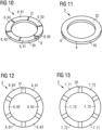
7 bis 17 verschiedene Ausführungsbeispiele für Kontaktbereiche eines Anregungselements für eine hier beschriebene optische Anordnung, -
18A bis 21D verschiedene exemplarische Biegeschwingungen, die im Betrieb einer Scheibe einer hier beschriebenen optischen Anordnung anregbar sind.
-
1 to 4 an optical arrangement described here according to a first embodiment in various views, -
5 a perspective view of a flexible film for an optical arrangement described here, -
6 a perspective sectional view of an optical arrangement described here according to a second embodiment, -
7 to 17 various embodiments of contact areas of an excitation element for an optical arrangement described here, -
18A to 21D various exemplary bending vibrations that can be excited during operation of a disk of an optical arrangement described here.
Die optische Anordnung 1 umfasst eine strahlungsdurchlässige Scheibe 2 und ein Anregungselement 3 an einer ersten Hauptseite 21 der Scheibe 2. Die optische Anordnung 1 ist insbesondere eine Abdeckung für eine Kamera oder eine Kameralinse. Vorzugsweise ist die Scheibe 2 strahlungsdurchlässig für Strahlung, die mit der Kamera erfasst werden soll. Die optische Anordnung 1 ist insbesondere Teil eines Linsenreinigungssystems für die Kameralinse.The
Das Anregungselement 3 ist ein piezokeramisches Anregungselement und mit einer Piezokeramik gebildet. Durch Anlegen einer Spannung an das Anregungselement 3 lässt sich dieses Ausdehnen oder Zusammenziehen. Damit ist mittels des Anregungselements 3 eine Deformation der Scheibe 2 induzierbar.The
Die Scheibe 2 ist kreisförmig ausgebildet und das Anregungselement 3 ist ringförmig ausgebildet. Ein Außendurchmesser 31 des Anregungselements 3 entspricht im Wesentlichen einem Durchmesser 23 der Scheibe 2. Der Außendurchmesser 31 beträgt zum Beispiel 21 mm und der Durchmesser 23 der Scheibe 2 beträgt beispielsweise ebenfalls 21 mm. Eine Dicke 24 der Scheibe 2 beträgt zum Beispiel 1,5 mm und eine Dicke 34 des Anregungselements 3 beträgt beispielsweise ebenfalls 1,5 mm. Die Dicken 24, 34 werden senkrecht zur ersten Hauptseite 21 gemessen.The
Die Scheibe 2 weist einen Zentralbereich 4 und einen umlaufenden Randbereich 5 auf. Der Randbereich 5 umschließt den Zentralbereich 4 in lateralen Richtungen bevorzugt vollständig. Laterale Richtungen sind dabei Folgenden Richtungen parallel zur ersten Hauptseite 21.The
Das Anregungselement 3 ist dazu eingerichtet, in dem Zentralbereich 4 eine rotationssymmetrische Biegemode anzuregen. Durch die rotationssymmetrische Biegemode wird die Scheibe 2 im Zentralbereich verformt, sodass im Zentralbereich 4 eine erste Biegeschwingung der Scheibe 2 angeregt wird. Die erste Biegeschwingung ist rotationssymmetrisch. Das heißt, im Betrieb der optischen Anordnung 1 weist die erste Biegeschwingung im Zentralbereich 4, bevorzugt in der Mitte der Scheibe 2, abwechselnd lokale Maxima und lokale Minima auf, die in Richtung des Randbereichs 4 abfallen. Im Randbereich 4 zeigt die erste Biegeschwingung im Wesentlichen keine Amplitude. Das heißt, mittels Anregung der rotationssymmetrischen Biegemode lässt sich keine Deformation beziehungsweise Bewegung der Scheibe 2 im Randbereich 5 erreichen.The
Darüber hinaus ist das Anregungselement 3 dazu eingerichtet, im Randbereich 5 nicht-rotationssymmetrische Biegemoden anzuregen. Insbesondere werden im bestimmungsgemäßen Betrieb im Randbereich 5 drei nicht-rotationssymmetrische Biegemoden angeregt. Eine Überlagerung der drei nicht-rotationssymmetrischen Biegemoden ergibt eine laufende Welle im Randbereich 5. Eine zweite Biegeschwingung, die durch die laufende Welle gebildet ist, weist lokale Maxima und lokale Minima im Randbereich auf, die sich während dem Betrieb der optischen Anordnung 1 im Randbereich 5 entlang einer Kontur der Scheibe 2 bewegen. Die lokalen Maxima und lokalen Minima der zweiten Biegeschwingungen fallen in Richtung des Zentralbereichs 4 linear ab.Furthermore, the
Im bestimmungsgemäßen Betrieb werden ferner die erste und zweite Biegeschwingung überlagert, sodass sich eine komplexe Gesamtbiegeschwingung ergibt. Mit der Überlagerung der ersten und zweiten Biegeschwingung kann erreicht werden, dass die gesamte Scheibe 2 sowohl im Zentralbereich 4 als auch im Randbereich 5 in Schwingung versetzt wird.During normal operation, the first and second bending vibrations are superimposed, resulting in a complex overall bending vibration. By superimposing the first and second bending vibrations, it can be achieved that the
Beispielsweise wird die optische Anordnung 1 als Abdeckung oder Schutz für eine Kamera oder Kameralinse verwendet. Dabei besteht grundsätzlich der Wunsch, die Kamera beziehungsweise Kameralinse vor Schmutz oder Wasser zu schützen und gegebenenfalls Schmutz und Wasser von der Kamera und Kameralinse zu entfernen, sprich die Scheibe 2 der optischen Anordnung 1 zu reinigen. Diese Reinigung wird durch Ultraschallreinigung erreicht. Dabei wird die Scheibe 2 mittels des Anregungselements 3 in Schwingung versetzt, sodass Verschmutzung oder Wasser von der Scheibe 2 entfernt werden. Die hier beschriebene optische Anordnung 1 kann zum Beispiel als Abdeckungen für optische Sensoren, beispielsweise im Automobilbereich, oder für Überwachungskameras, insbesondere im Außenbereich, dienen.For example, the
Die optische Anordnung 1 weist ferner eine flexible Folie 10 auf. Die flexible Folie 10 weist Leitungsbereiche auf, die mit dem Anregungselement 3 elektrisch leitfähig verbunden sind. Die flexible Folie 10 ist zwischen der Scheibe 2 und dem Anregungselement 3 angeordnet. Die flexible Folie 10 weist einen Steg 12 auf, der Anschlussstellen umfasst. Die Anschlussstellen sind zur elektrischen Kontaktierung ausgebildet. Die Anschlussstellen sind elektrisch leitfähig mit den Leitungsbereichen der flexiblen Folie 10 verbunden. Über den Steg kann also das Anregungselement 3 elektrisch kontaktiert werden.The
Der Verbund aus der Scheibe 2, dem Anregungselement 3 und der flexiblen Folie 10 ist in einem Gehäuse 100 angeordnet. The composite of the
Insbesondere ist dieser Verbund in einer Öffnung 103 des Gehäuses 100 angeordnet. Eine mechanische Verbindung zwischen dem Gehäuse 100 und der Scheibe 2 und dem Anregungselement 3 ist insbesondere ausschließlich durch die flexible Folie 10 und einem als Folie ausgebildeten Abdeckelement 13 gebildet.In particular, this composite is arranged in an
Das Gehäuse 100 weist zum Beispiel einen als Gewinde 101 ausgebildeten ersten Teil und einen als Abdeckung 102 ausgebildeten zweiten Teil auf. Zwischen dem Gewinde 101 und der Abdeckung 102 kann die flexible Folie 10 eingeklemmt oder verklebt sein. Beispielsweise wird die Abdeckung 102 auf das Gewinde 101 geschraubt oder geklebt.The
Das Abdeckelement 13 ist an einer zweiten Hauptseite 22 der Scheibe 2 angeordnet, die der ersten Hauptseite 21 gegenüberliegt. Das Abdeckelement 13 ist als Folie ausgebildet und mit Polyimid gebildet. Das Abdeckelement 13 verschließt zusammen mit der Scheibe 2 die Öffnung 103 des Gehäuses 100 hermetisch. Dazu greift das Abdeckelement 13 von der Scheibe 2 auf das Gehäuse 100 über. Ein Spalt zwischen dem Gehäuse 100 und der Scheibe 2 wird damit hermetisch verschlossen.The
Das Abdeckelement 13 ist ringförmig ausgebildet und weist einen Außendurchmesser von 30 mm auf. In Blick auf die zweite Hauptseite 22 ist in einer Öffnung des Abdeckelements 13 die Scheibe 2, insbesondere der Zentralbereich 5 der Scheibe 2 zu erkennen.The
Dadurch, dass eine mechanische Verbindung zwischen der Scheibe 2 und dem Gehäuse 100 lediglich durch die Folien 10, 13 ausgebildet ist, weist die Scheibe 2 eine verhältnismäßig hohe Bewegungsfreiheit auf. Das heißt, eine Dämpfung der Gesamtbiegeschwingung der Scheibe 2 ist verhältnismäßig gering.Because the mechanical connection between the
Die flexible Folie 10 weist einen Steg 12 auf, der sich quer, insbesondere senkrecht, zu einer Haupterstreckungsrichtung der flexiblen Folie 10 erstreckt. Der Steg 12 weist die Anschlussbereiche auf, mit denen die Leitungsbereiche und letztlich das Anregungselement 3 elektrisch kontaktierbar sind. Durch die Anordnung des Stegs senkrecht zur Haupterstreckungsebene der flexiblen Folie 10 sind diese Anschlussstellen vorteilhafterweise besonders einfach extern zugänglich, wie auch in
Die weitere flexible Folie 11 ist insbesondere an einer von der ersten Hauptseite 21 abgewandten Rückseite 32 des Anregungselements 3 angeordnet. Die weitere flexible Folie 11 weist wie die flexible Folie 10 Leitungsbereiche und einen Steg auf. Insbesondere stimmt die weitere flexible Folie 11 mit der flexiblen Folie 10 in nahezu allen Merkmalen überein, mit Ausnahme der Anordnung an dem Anregungselement 3.The further
Mittels der flexiblen Folie 10 lässt sich insbesondere die Vorderseite 31 des Anregungselements 3 elektrisch leitfähig kontaktieren und mittels der weiteren flexiblen Folie 11 lässt sich beispielsweise die Rückseite 32 des Anregungselements 3 elektrisch leitfähig kontaktieren. Mittels der weiteren flexiblen Folie 11 ist insbesondere ebenfalls eine mechanische Verbindung zu dem Gehäuse 100 gebildet.By means of the
Das Anregungselement 3 weist in dem Ausführungsbeispiel der
An die Kontaktbereiche erster Art 61 wird im bestimmungsgemäßen Betrieb eine erste Spannung, an die Kontaktbereiche zweiter Art 62 eine zweite Spannung und an die Kontaktbereiche dritter Art 63 eine dritte Spannung angelegt. Durch die angelegten Spannungen kann das Anregungselement 3, welches eine Piezokeramik umfasst, verformt werden. Diese Verformung wird auf die Scheibe 2 übertragen. Bei geeigneter Ansteuerung des Anregungselements 3 kann damit die Scheibe in Schwingung versetzt werden. Das heißt, mittels der ersten, zweiten und dritten Spannung lassen sich in der Scheibe 2 drei nicht-rotationssymmetrische Biegemoden im Randbereich 5 anregen. Eine Überlagerung dieser Biegemoden ergibt die zweite Biegeschwingung.During normal operation, a first voltage is applied to the first-type contact areas 61, a second voltage to the second-type contact areas 62, and a third voltage to the third-type contact areas 63. The applied voltages can deform the
Im Ausführungsbeispiel der
Die erste, zweite und dritte Spannung weisen jeweils dieselbe Amplitude und Frequenz auf. Insbesondere handelt es sich bei der ersten, zweiten und dritten Spannung jeweils um eine harmonische Wechselspannung. Die Amplitude beträgt beispielsweise 10 V und die Frequenz beträgt beispielsweise 16,78 kHz. Die zweite Spannung ist um 120° phasenversetzt zur ersten Spannung. Die dritte Spannung ist um 240° phasenversetzt zur ersten Spannung.The first, second, and third voltages each have the same amplitude and frequency. Specifically, the first, second, and third voltages are each a harmonic alternating voltage. The amplitude is, for example, 10 V and the frequency is, for example, 16.78 kHz. The second voltage is 120° out of phase with the first voltage. The third voltage is 240° out of phase with the first voltage.
Ferner wird im Betrieb an die Kontaktbereiche 6 eine vierte Spannung angelegt, die gemeinsam an alle Kontaktbereiche 6 angelegt wird. Die vierte Spannung ist vorzugsweise ebenfalls eine harmonische Wechselspannung und weist eine Frequenz von 10 V und eine Frequenz von 34,5 kHz auf. Mittels der vierten Spannung lässt sich die rotationssymmetrische Biegemode und folglich die erste Biegeschwingung im Zentralbereich 4 der Scheibe 2 anregen. Durch gleichzeitiges Anlegen beziehungsweise geeignetes Überlagern der der ersten, zweiten, dritten und vierten Spannung kann somit die Gesamtbiegeschwingung erzeugt werden.Furthermore, during operation, a fourth voltage is applied to the
An die Kontaktbereiche erster Art 61 lässt sich in analoger Weise, wie in Zusammenhang mit der
Abweichend zu den
Über die Metallisierung 9 kann der Massekontakt 8 von der Rückseite 32 auf die Vorderseite 31 gezogen werden. Das heißt, die Metallisierung 9 bildet eine Umkontaktierung für den Massekontakt 8. Damit ist der Massekontakt 8 wie die vorderseitigen Kontaktelemente 6 über die Vorderseite 31 elektrisch kontaktierbar. Damit kann das Anregungselement 3, wie beispielsweise in
Es ist ebenso möglich, dass der Massekontakt 8 an der Vorderseite 31 angeordnet ist und die Rückseite 32 rückseitige Kontaktbereiche 7 aufweist, wobei der Massekontakt 8 der Vorderseite 31 über die Metallisierung 9 auf die Rückseite 32 gezogen ist. In diesem Fall kann eine elektrische Kontaktierung des Anregungselements 3 ausschließlich über die Rückseite 32 erfolgen.It is also possible for the
Ebenso ist es möglich, dass das Anregungselement 3 vorderseitige Kontaktbereiche 6 und rückseitige Kontaktbereiche 7 aufweist. Über Metallisierungen 9 an der Seitenfläche 35 können die vorderseitigen Kontaktelemente 6 auf die Rückseite 32 umkontaktiert werden oder die rückseitigen Kontaktelemente 7 auf die Vorderseite 31 umkontaktiert werden. In diesem Fall ist es möglich, dass eine elektrische Kontaktierung der vorderseitigen und rückseitigen Kontaktbereiche 6, 7 ausschließlich aus Richtung der Vorderseite 31 oder der Rückseite 32 erfolgen kann.It is also possible for the
In einer Projektion auf eine gemeinsame Ebene parallel zur Vorderseite 31, sprich beispielsweise einer Ebene, in der die Vorderseite 31 liegt, überlappen die vorderseitigen Kontaktbereiche 6 mit den rückseitigen Kontaktbereichen 7. Eine entsprechende Überlappung ist insbesondere vollständig. Das heißt, in der Projektion auf die gemeinsame Ebene überdecken die vorderseitigen Kontaktbereiche 6 die rückseitigen Kontaktbereiche 7 vollständig und umgekehrt. Dabei überlappt jeder vorderseitige Kontaktbereich erster Art 61 mit einem rückseitigen Kontaktbereich zweiter Art 62. Jeder vorderseitige Kontaktbereich zweiter Art 62 überlappt mit einem rückseitigen Kontaktbereich dritter Art 73. Jeder vorderseitige Kontaktbereich dritter Art 63 überlappt mit einem rückseitigen Kontaktbereich erster Art 71.In a projection onto a common plane parallel to the
Eine elektrische Kontaktierung der Kontaktbereiche 6, 7 erfolgt insbesondere masselos. Damit ist gemeint, dass das Anregungselement 3 keinen Massekontakt 8 aufweist. Insbesondere lässt sich an die Kontaktbereiche 6, 7 eine modifizierte erste Spannung, eine modifizierte zweite Spannung, eine modifizierte dritte Spannung und die vierte Spannung wie oben erläutert anlegen. Die modifizierte erste Spannung entspricht der ersten Spannung bis auf in der Amplitude. Die modifizierte erste Spannung weist eine Amplitude auf, die um einen Faktor
Wie bei der Anordnung der Kontaktbereiche 6, 7 gemäß der
Die vorderseitigen Kontaktbereiche 6 und die rückseitigen Kontaktbereiche 7 sind in einer Projektion in eine gemeinsame Ebene beispielsweise der Vorderseite 31 versetzt zueinander angeordnet. Damit ist insbesondere gemeint, dass in der Projektion jeder vorderseitige Kontaktbereich 6 mit mindestens zwei rückseitigen Kontaktbereichen 7 überlappt und umgekehrt. Im Vergleich zu den
Bei den Ausführungsbeispielen der
Durch diese Anordnung der vorderseitigen und rückseitigen Kontaktbereiche 6, 7 wird eine vorgegebene Polungsrichtung 60 erfüllt, dargestellt durch die Pfeile 60 in den
Die Polungsrichtung 60 ist durch die Abfolge der Kontaktbereiche erster Art, zweiter Art und dritter Art vorgegeben. Durch die Polungsrichtung 60 ist insbesondere sichergestellt, dass im Betrieb ein Phasenversatz der ersten Spannung zur zweiten und dritten Spannung derart erfüllt ist, dass eine Überlagerung der drei Biegemoden eine stehende Welle erzeugt. Dies wird in den
Bei der ersten Biegeschwingung verformt sich die Scheibe 2 im Zentralbereich 5. Das heißt, eine Deformation 80 der Scheibe 2 ist im Zentralbereich maximal. Im Ausführungsbeispiel der
Wie aus den
Damit lässt sich durch eine Kombination der ersten und zweite Biegeschwingung, also einer Überlagerung der rotationssymmetrischen Biegemoden und nicht-rotationssymmetrischen Biegemoden eine Gesamtbiegeschwingung anregen, durch die die Scheibe 2 im Wesentlichen in allen Bereichen im Betrieb der optischen Anordnung 1 in Schwingung versetzt wird. Damit kann die optische Anordnung 1 mittels Ultraschallreinigung von Schmutz, Wasserrückständen oder Regen mittels der Gesamtbiegeschwingung gereinigt werden. Eine Reinigungswirkung ist dabei vorteilhafterweise nicht auf den Zentralbereich beschränkt, sondern kann in allen Bereichen der Scheibe 2 erzielt werden.Thus, by combining the first and second bending modes, i.e., by superimposing the rotationally symmetric bending modes and non-rotationally symmetric bending modes, a total bending mode can be excited, causing the
BezugszeichenReference symbol
- 11
- optische Anordnungoptical arrangement
- 22
- strahlungsdurchlässige Scheiberadiation-permeable pane
- 33
- piezoelektrisches Anregungselementpiezoelectric excitation element
- 44
- ZentralbereichCentral area
- 55
- Randbereichperipheral area
- 66
- vorderseitige Kontaktbereichefront contact areas
- 77
- rückseitige Kontaktbereicherear contact areas
- 88
- MassekontaktGround contact
- 99
- MetallisierungMetallization
- 1010
- flexible Folieflexible film
- 1111
- weitere flexible Folieadditional flexible film
- 1212
- Stegweb
- 1313
- AbdeckfolieCover film
- 2121
- erste Hauptseitefirst main page
- 2222
- zweite Hauptseitesecond main page
- 2323
- Durchmesserdiameter
- 2424
- Dickethickness
- 3131
- Vorderseitefront
- 3232
- Rückseiteback
- 3333
- Außendurchmesser des AnregungselementsOuter diameter of the excitation element
- 3434
- Dickethickness
- 3535
- Seitenflächeside surface
- 6060
- PolungsrichtungPolarity direction
- 6161
- vorderseitiger Kontakt erster Artfront contact of the first kind
- 6262
- vorderseitiger Kontakt zweiter Artfront contact of the second kind
- 6363
- vorderseitiger Kontakt dritter Artfront contact of the third kind
- 7171
- rückseitiger Kontakt erster Artrear contact of the first kind
- 7272
- rückseitiger Kontakt zweiter Artrear contact of the second kind
- 7373
- rückseitiger Kontakt dritter Artrear contact of the third kind
- 8080
- Deformationdeformation
- 100100
- GehäuseHousing
- 101101
- Gewindethread
- 102102
- Abdeckungcover
ZITATE ENTHALTEN IN DER BESCHREIBUNGQUOTES CONTAINED IN THE DESCRIPTION
Diese Liste der vom Anmelder aufgeführten Dokumente wurde automatisiert erzeugt und ist ausschließlich zur besseren Information des Lesers aufgenommen. Die Liste ist nicht Bestandteil der deutschen Patent- bzw. Gebrauchsmusteranmeldung. Das DPMA übernimmt keinerlei Haftung für etwaige Fehler oder Auslassungen.This list of documents submitted by the applicant was generated automatically and is included solely for the convenience of the reader. This list is not part of the German patent or utility model application. The DPMA assumes no liability for any errors or omissions.
Zitierte PatentliteraturCited patent literature
- US 10,682,675 B2 [0004]US 10,682,675 B2 [0004]
Claims (20)
Priority Applications (2)
| Application Number | Priority Date | Filing Date | Title |
|---|---|---|---|
| DE102023136551.7A DE102023136551A1 (en) | 2023-12-22 | 2023-12-22 | Optical arrangement and method for operating an optical arrangement |
| PCT/EP2024/084091 WO2025131624A1 (en) | 2023-12-22 | 2024-11-29 | Optical arrangement and method for operating an optical arrangement |
Applications Claiming Priority (1)
| Application Number | Priority Date | Filing Date | Title |
|---|---|---|---|
| DE102023136551.7A DE102023136551A1 (en) | 2023-12-22 | 2023-12-22 | Optical arrangement and method for operating an optical arrangement |
Publications (1)
| Publication Number | Publication Date |
|---|---|
| DE102023136551A1 true DE102023136551A1 (en) | 2025-06-26 |
Family
ID=93799587
Family Applications (1)
| Application Number | Title | Priority Date | Filing Date |
|---|---|---|---|
| DE102023136551.7A Pending DE102023136551A1 (en) | 2023-12-22 | 2023-12-22 | Optical arrangement and method for operating an optical arrangement |
Country Status (2)
| Country | Link |
|---|---|
| DE (1) | DE102023136551A1 (en) |
| WO (1) | WO2025131624A1 (en) |
Citations (19)
| Publication number | Priority date | Publication date | Assignee | Title |
|---|---|---|---|---|
| JPH11260781A (en) * | 1998-03-10 | 1999-09-24 | Dainippon Screen Mfg Co Ltd | Substrate treating equipment |
| JP2001359287A (en) * | 2000-06-12 | 2001-12-26 | Minolta Co Ltd | Surface acoustic wave optical element |
| US20040047625A1 (en) * | 2002-05-17 | 2004-03-11 | Junichi Ito | Electronic imaging apparatus with anti-dust function |
| JP2007193126A (en) * | 2006-01-19 | 2007-08-02 | Olympus Imaging Corp | Imaging apparatus and camera |
| EP1821519A1 (en) * | 2006-02-17 | 2007-08-22 | Canon Kabushiki Kaisha | Image capturing apparatus and control method therefor |
| JP2008228366A (en) * | 2007-03-08 | 2008-09-25 | Canon Inc | Vibration actuator and optical apparatus including the vibration actuator |
| US20080247059A1 (en) * | 2007-04-03 | 2008-10-09 | Shuxiang Dong | Miniature Piezoelectric Motor and Method of Driving Elements Using Same |
| US20100220394A1 (en) * | 2008-10-10 | 2010-09-02 | Olympus Imaging Corp. | Imaging apparatus |
| US20100315712A1 (en) * | 2009-06-15 | 2010-12-16 | Olympus Imaging Corp. | Vibrating device and image equipment having the same |
| US8599302B2 (en) * | 2010-09-03 | 2013-12-03 | Olympus Imaging Corp. | Vibrating device and image equipment having the same |
| US20140218588A1 (en) * | 2011-10-20 | 2014-08-07 | Cannon Kabushiki Kaisha | Dust removing device and imaging device |
| JP2017085276A (en) * | 2015-10-26 | 2017-05-18 | オリンパス株式会社 | Droplet elimination device, image device having droplet elimination device, droplet elimination device control method, and droplet elimination device control program |
| JP2017170303A (en) * | 2016-03-22 | 2017-09-28 | オリンパス株式会社 | Droplet removal device, imaging device having droplet removal device, control method of droplet removal device, and control program of droplet removal device |
| US20170361360A1 (en) * | 2016-06-20 | 2017-12-21 | Texas Instruments Incorporated | Ultrasonic lens cleaning with travelling wave excitation |
| US20180188526A1 (en) * | 2016-12-30 | 2018-07-05 | Texas Instruments Incorporated | Ultrasound Lens Structure Cleaner Architecture and Method Using Standing and Traveling Waves |
| US20180284268A1 (en) * | 2017-03-29 | 2018-10-04 | Luminar Technologies, Inc. | Ultrasonic vibrations on a window in a lidar system |
| EP3623059A1 (en) * | 2017-05-12 | 2020-03-18 | Murata Manufacturing Co., Ltd. | Vibration device |
| CN112887522A (en) * | 2019-11-29 | 2021-06-01 | 华为机器有限公司 | Piezoelectric actuating device, camera module and electronic equipment |
| WO2024056273A1 (en) * | 2022-09-14 | 2024-03-21 | Tdk Electronics Ag | Transducer component |
Family Cites Families (6)
| Publication number | Priority date | Publication date | Assignee | Title |
|---|---|---|---|---|
| US8218059B2 (en) * | 2008-10-10 | 2012-07-10 | Olympus Imaging Corp | Digital camera |
| DE112016004551T5 (en) * | 2015-12-24 | 2018-07-12 | Murata Manufacturing Co., Ltd. | SWINGING DEVICE, METHOD FOR CONTROLLING THE SAME AND CAMERA |
| US10682675B2 (en) | 2016-11-01 | 2020-06-16 | Texas Instruments Incorporated | Ultrasonic lens cleaning system with impedance monitoring to detect faults or degradation |
| WO2020230419A1 (en) * | 2019-05-16 | 2020-11-19 | 株式会社村田製作所 | Optical device and optical unit comprising optical device |
| WO2022091752A1 (en) * | 2020-10-28 | 2022-05-05 | 株式会社村田製作所 | Vibration device and imaging device |
| JP7088259B2 (en) * | 2020-10-30 | 2022-06-21 | 株式会社村田製作所 | Cleaning device, imaging unit equipped with cleaning device, and cleaning method |
-
2023
- 2023-12-22 DE DE102023136551.7A patent/DE102023136551A1/en active Pending
-
2024
- 2024-11-29 WO PCT/EP2024/084091 patent/WO2025131624A1/en active Pending
Patent Citations (19)
| Publication number | Priority date | Publication date | Assignee | Title |
|---|---|---|---|---|
| JPH11260781A (en) * | 1998-03-10 | 1999-09-24 | Dainippon Screen Mfg Co Ltd | Substrate treating equipment |
| JP2001359287A (en) * | 2000-06-12 | 2001-12-26 | Minolta Co Ltd | Surface acoustic wave optical element |
| US20040047625A1 (en) * | 2002-05-17 | 2004-03-11 | Junichi Ito | Electronic imaging apparatus with anti-dust function |
| JP2007193126A (en) * | 2006-01-19 | 2007-08-02 | Olympus Imaging Corp | Imaging apparatus and camera |
| EP1821519A1 (en) * | 2006-02-17 | 2007-08-22 | Canon Kabushiki Kaisha | Image capturing apparatus and control method therefor |
| JP2008228366A (en) * | 2007-03-08 | 2008-09-25 | Canon Inc | Vibration actuator and optical apparatus including the vibration actuator |
| US20080247059A1 (en) * | 2007-04-03 | 2008-10-09 | Shuxiang Dong | Miniature Piezoelectric Motor and Method of Driving Elements Using Same |
| US20100220394A1 (en) * | 2008-10-10 | 2010-09-02 | Olympus Imaging Corp. | Imaging apparatus |
| US20100315712A1 (en) * | 2009-06-15 | 2010-12-16 | Olympus Imaging Corp. | Vibrating device and image equipment having the same |
| US8599302B2 (en) * | 2010-09-03 | 2013-12-03 | Olympus Imaging Corp. | Vibrating device and image equipment having the same |
| US20140218588A1 (en) * | 2011-10-20 | 2014-08-07 | Cannon Kabushiki Kaisha | Dust removing device and imaging device |
| JP2017085276A (en) * | 2015-10-26 | 2017-05-18 | オリンパス株式会社 | Droplet elimination device, image device having droplet elimination device, droplet elimination device control method, and droplet elimination device control program |
| JP2017170303A (en) * | 2016-03-22 | 2017-09-28 | オリンパス株式会社 | Droplet removal device, imaging device having droplet removal device, control method of droplet removal device, and control program of droplet removal device |
| US20170361360A1 (en) * | 2016-06-20 | 2017-12-21 | Texas Instruments Incorporated | Ultrasonic lens cleaning with travelling wave excitation |
| US20180188526A1 (en) * | 2016-12-30 | 2018-07-05 | Texas Instruments Incorporated | Ultrasound Lens Structure Cleaner Architecture and Method Using Standing and Traveling Waves |
| US20180284268A1 (en) * | 2017-03-29 | 2018-10-04 | Luminar Technologies, Inc. | Ultrasonic vibrations on a window in a lidar system |
| EP3623059A1 (en) * | 2017-05-12 | 2020-03-18 | Murata Manufacturing Co., Ltd. | Vibration device |
| CN112887522A (en) * | 2019-11-29 | 2021-06-01 | 华为机器有限公司 | Piezoelectric actuating device, camera module and electronic equipment |
| WO2024056273A1 (en) * | 2022-09-14 | 2024-03-21 | Tdk Electronics Ag | Transducer component |
Also Published As
| Publication number | Publication date |
|---|---|
| WO2025131624A1 (en) | 2025-06-26 |
Similar Documents
| Publication | Publication Date | Title |
|---|---|---|
| EP2297798B1 (en) | Method for tuning a resonant frequency of a piezoelectric component | |
| DE69422867T2 (en) | Design of a broadband phased group converter with frequency controlled two-dimensional capability and process for its production | |
| DE69407592T2 (en) | HIGH PRESSURE LOW IMPEDANCE ELECTROSTATIC CONVERTER | |
| EP4220278B1 (en) | Optical monitoring device | |
| DE102005031128A1 (en) | Angular velocity detector | |
| DE112017006066T5 (en) | VIBRATING, CAMERA WATER DROP REMOVAL DEVICE AND CAMERA | |
| DE4217559A1 (en) | Ultrasonic cleaning appts. for exposed surface of imaging system - projects liq. film on to convex portion of window for atomisation by LV excited piezoelectric resonance | |
| DE102012207160A1 (en) | Sensor arrangement comprising a planar vehicle component and an ultrasonic sensor | |
| WO2011073414A2 (en) | Oscillatory system for an ultrasonic transducer and method for producing the oscillatory system | |
| EP3799966A2 (en) | Acoustic transducer and method for generating/receiving an acoustic wave | |
| EP4291338B1 (en) | Device and method for producing a device | |
| DE102018101367B4 (en) | SELF-CLEANING LENS SYSTEM | |
| DE102023136551A1 (en) | Optical arrangement and method for operating an optical arrangement | |
| DE4021926C2 (en) | Vehicle mirror | |
| DE102017209823A1 (en) | ultrasonic sensor | |
| DE69408230T2 (en) | Ultrasonic device for detecting foreign bodies on the outer surface of a pane, pane and pane equipped with such a device, intended for fitting with an ultrasonic detection device | |
| DE102019132086A1 (en) | ULTRASONIC TRANSDUCER, METHOD FOR THE PRODUCTION THEREOF, AND ULTRASONIC IMAGING DEVICE | |
| DE2518550A1 (en) | PICTURE RECORDING EAR WITH PYROELECTRIC PHOTOCATODE | |
| DE102005018867B4 (en) | Piezoelectric micro-power converter | |
| DE2510977A1 (en) | RECEPTION AND RADIATION DEVICE OF ELECTROMAGNETIC WAVES | |
| EP4554890A1 (en) | Method for producing a layer structure for a mems device, and mems device comprising such a layer structure | |
| DE112019006369T5 (en) | Piezoelectric converter | |
| DE102005061343B4 (en) | Ultrasonic transducer with self-supporting matching layer and method of manufacture | |
| DE102005037724B4 (en) | Piezoelectric ultrasonic transducer and its use for determining the instantaneous height of an air spring | |
| DE102009028356A1 (en) | Micromechanical component, light deflection device and production method for a micromechanical component and a light deflection device |
Legal Events
| Date | Code | Title | Description |
|---|---|---|---|
| R012 | Request for examination validly filed | ||
| R016 | Response to examination communication |