DE102023136070A1 - Forming machine with multiple workstations - Google Patents
Forming machine with multiple workstations Download PDFInfo
- Publication number
- DE102023136070A1 DE102023136070A1 DE102023136070.1A DE102023136070A DE102023136070A1 DE 102023136070 A1 DE102023136070 A1 DE 102023136070A1 DE 102023136070 A DE102023136070 A DE 102023136070A DE 102023136070 A1 DE102023136070 A1 DE 102023136070A1
- Authority
- DE
- Germany
- Prior art keywords
- transport
- unit
- tool
- work
- forming machine
- Prior art date
- Legal status (The legal status is an assumption and is not a legal conclusion. Google has not performed a legal analysis and makes no representation as to the accuracy of the status listed.)
- Pending
Links
Images


Classifications
-
- B—PERFORMING OPERATIONS; TRANSPORTING
- B21—MECHANICAL METAL-WORKING WITHOUT ESSENTIALLY REMOVING MATERIAL; PUNCHING METAL
- B21F—WORKING OR PROCESSING OF METAL WIRE
- B21F23/00—Feeding wire in wire-working machines or apparatus
- B21F23/005—Feeding discrete lengths of wire or rod
-
- B—PERFORMING OPERATIONS; TRANSPORTING
- B21—MECHANICAL METAL-WORKING WITHOUT ESSENTIALLY REMOVING MATERIAL; PUNCHING METAL
- B21D—WORKING OR PROCESSING OF SHEET METAL OR METAL TUBES, RODS OR PROFILES WITHOUT ESSENTIALLY REMOVING MATERIAL; PUNCHING METAL
- B21D11/00—Bending not restricted to forms of material mentioned in only one of groups B21D5/00, B21D7/00, B21D9/00; Bending not provided for in groups B21D5/00 - B21D9/00; Twisting
- B21D11/10—Bending specially adapted to produce specific articles, e.g. leaf springs
-
- B—PERFORMING OPERATIONS; TRANSPORTING
- B21—MECHANICAL METAL-WORKING WITHOUT ESSENTIALLY REMOVING MATERIAL; PUNCHING METAL
- B21D—WORKING OR PROCESSING OF SHEET METAL OR METAL TUBES, RODS OR PROFILES WITHOUT ESSENTIALLY REMOVING MATERIAL; PUNCHING METAL
- B21D43/00—Feeding, positioning or storing devices combined with, or arranged in, or specially adapted for use in connection with, apparatus for working or processing sheet metal, metal tubes or metal profiles; Associations therewith of cutting devices
- B21D43/006—Feeding elongated articles, such as tubes, bars, or profiles
-
- B—PERFORMING OPERATIONS; TRANSPORTING
- B21—MECHANICAL METAL-WORKING WITHOUT ESSENTIALLY REMOVING MATERIAL; PUNCHING METAL
- B21D—WORKING OR PROCESSING OF SHEET METAL OR METAL TUBES, RODS OR PROFILES WITHOUT ESSENTIALLY REMOVING MATERIAL; PUNCHING METAL
- B21D43/00—Feeding, positioning or storing devices combined with, or arranged in, or specially adapted for use in connection with, apparatus for working or processing sheet metal, metal tubes or metal profiles; Associations therewith of cutting devices
- B21D43/02—Advancing work in relation to the stroke of the die or tool
- B21D43/04—Advancing work in relation to the stroke of the die or tool by means in mechanical engagement with the work
- B21D43/10—Advancing work in relation to the stroke of the die or tool by means in mechanical engagement with the work by grippers
- B21D43/105—Manipulators, i.e. mechanical arms carrying a gripper element having several degrees of freedom
-
- B—PERFORMING OPERATIONS; TRANSPORTING
- B21—MECHANICAL METAL-WORKING WITHOUT ESSENTIALLY REMOVING MATERIAL; PUNCHING METAL
- B21D—WORKING OR PROCESSING OF SHEET METAL OR METAL TUBES, RODS OR PROFILES WITHOUT ESSENTIALLY REMOVING MATERIAL; PUNCHING METAL
- B21D7/00—Bending rods, profiles, or tubes
- B21D7/12—Bending rods, profiles, or tubes with program control
-
- B—PERFORMING OPERATIONS; TRANSPORTING
- B21—MECHANICAL METAL-WORKING WITHOUT ESSENTIALLY REMOVING MATERIAL; PUNCHING METAL
- B21F—WORKING OR PROCESSING OF METAL WIRE
- B21F1/00—Bending wire other than coiling; Straightening wire
- B21F1/006—Bending wire other than coiling; Straightening wire in 3D with means to rotate the tools about the wire axis
-
- B—PERFORMING OPERATIONS; TRANSPORTING
- B21—MECHANICAL METAL-WORKING WITHOUT ESSENTIALLY REMOVING MATERIAL; PUNCHING METAL
- B21K—MAKING FORGED OR PRESSED METAL PRODUCTS, e.g. HORSE-SHOES, RIVETS, BOLTS OR WHEELS
- B21K27/00—Handling devices, e.g. for feeding, aligning, discharging, Cutting-off means; Arrangement thereof
- B21K27/02—Feeding devices for rods, wire, or strips
- B21K27/04—Feeding devices for rods, wire, or strips allowing successive working steps
-
- B—PERFORMING OPERATIONS; TRANSPORTING
- B21—MECHANICAL METAL-WORKING WITHOUT ESSENTIALLY REMOVING MATERIAL; PUNCHING METAL
- B21D—WORKING OR PROCESSING OF SHEET METAL OR METAL TUBES, RODS OR PROFILES WITHOUT ESSENTIALLY REMOVING MATERIAL; PUNCHING METAL
- B21D43/00—Feeding, positioning or storing devices combined with, or arranged in, or specially adapted for use in connection with, apparatus for working or processing sheet metal, metal tubes or metal profiles; Associations therewith of cutting devices
- B21D43/02—Advancing work in relation to the stroke of the die or tool
- B21D43/04—Advancing work in relation to the stroke of the die or tool by means in mechanical engagement with the work
- B21D43/05—Advancing work in relation to the stroke of the die or tool by means in mechanical engagement with the work specially adapted for multi-stage presses
-
- B—PERFORMING OPERATIONS; TRANSPORTING
- B21—MECHANICAL METAL-WORKING WITHOUT ESSENTIALLY REMOVING MATERIAL; PUNCHING METAL
- B21D—WORKING OR PROCESSING OF SHEET METAL OR METAL TUBES, RODS OR PROFILES WITHOUT ESSENTIALLY REMOVING MATERIAL; PUNCHING METAL
- B21D7/00—Bending rods, profiles, or tubes
- B21D7/06—Bending rods, profiles, or tubes in press brakes or between rams and anvils or abutments; Pliers with forming dies
Landscapes
- Engineering & Computer Science (AREA)
- Mechanical Engineering (AREA)
- Bending Of Plates, Rods, And Pipes (AREA)
- Multi-Process Working Machines And Systems (AREA)
Abstract
Eine numerisch gesteuerte Umformmaschine (100) zur Herstellung komplex gestalteter Formteile aus geraden Werkstücken (WS) umfasst mehrere Arbeitsstationen, die eine Ladestation (400) und wenigstens zwei dieser nachgeschaltete Bearbeitungsstationen (410, 420) umfassen, sowie ein Maschinengestell zum Montieren von werkzeugtragenden Arbeitseinheiten zur Bildung von Arbeitsstationen. Ein Transportsystem (500) zum Transportieren aufeinanderfolgender Werkstücke (WS) von der Ladestation (400) zu nachgeschalteten Arbeitsstationen unter der Steuerung durch die Steuereinheit weist mehrere Transporteinheiten (520) auf, die jeweils eine Greifeinheit (560) zum Greifen eines Werkstücks aufweisen und unter Steuerung durch die Steuereinheit (190) im Pendelbetrieb zwischen zwei jeweils einer Arbeitsstation zugeordneten Endpositionen (522-1, 522-2) eines Pendelhubs hin und her bewegbar sind. Die Umformmaschine umfasst Komponenten eines Koordinatenabgleichsystems zum Abgleichen von Koordinaten zwischen einem einer Transporteinheit zugeordneten Transport-Koordinatensystem (TKS) und einem einer jeweiligen Arbeitsstation zugeordneten Werkzeug-Koordinatensystem (WKS) zur Ermittlung von Koordinatentransformationsdaten. Die Steuereinheit ist dazu konfiguriert, eine Transporteinheit unter Verwendung der Koordinatentransformationsdaten derart zu steuern, dass eine Greifeinheit (560) der Transporteinheit positionsgenau auf eine im Werkzeug-Koordinatensystem vorgebbare Zielposition steuerbar ist.

Description
ANWENDUNGSGEBIET UND STAND DER TECHNIKFIELD OF APPLICATION AND STATE OF THE ART
Die Erfindung bezieht sich auf eine Umformmaschine zur Herstellung komplex gestalteter Formteile aus geraden Werkstücken aus Draht oder Rohr unter Steuerung einer computernumerischen Steuereinheit gemäß dem Oberbegriff von Anspruch 1 sowie auf ein Verfahren zum Einrichten einer solchen Umformmaschine.The invention relates to a forming machine for producing complex shaped parts from straight workpieces made of wire or tube under the control of a computer numerical control unit according to the preamble of
Eine computernumerisch gesteuerte Umformmaschine der hier betrachteten Art weist mehrere Arbeitsstationen auf. Zu den Arbeitsstationen gehört eine Ladestation, über die die Umformmaschine mit den zu verarbeitenden, üblicherweise geraden Werkstücken beladen werden kann, sowie eine der Ladestation nachgeschaltete erste Bearbeitungsstation und wenigstens eine dieser ersten Bearbeitungsstation nachgeschaltete zweite Bearbeitungsstation. Eine Bearbeitungsstation ist eine Arbeitsstation, in der das Werkstück bearbeitet und dadurch in seinen Eigenschaften, insbesondere hinsichtlich seiner Form bzw. Gestalt, verändert wird. Wenigstens zwei der Bearbeitungsstationen sind als Umformstationen ausgelegt, an denen das Werkstück z.B. durch Biegen oder Pressen umgeformt wird. Mit der Umformmaschine werden unter der Steuerung durch die Steuereinheit mehrere Umformoperationen realisiert, zusätzlich können auch andere Bearbeitungen vorgesehen sein, z.B. eine spanende Bearbeitung.A computer-numerically controlled forming machine of the type considered here has several workstations. The workstations include a loading station, via which the forming machine can be loaded with the workpieces to be processed, usually straight ones, as well as a first processing station downstream of the loading station and at least one second processing station downstream of this first processing station. A processing station is a workstation in which the workpiece is processed and its properties, particularly with regard to its shape or form, are thereby changed. At least two of the processing stations are designed as forming stations, where the workpiece is formed, for example, by bending or pressing. The forming machine performs several forming operations under the control of the control unit; additional processing operations, such as machining, can also be provided.
Die zu verarbeitenden Werkstücke durchlaufen die Arbeitsstationen sukzessive. Hierzu weist die Umformmaschine ein Transportsystem zum Transportieren aufeinanderfolgender Werkstücke von der Ladestation zu nachgeschalteten Arbeitsstationen auf. Das Transportsystem arbeitet unter der Steuerung durch die Steuereinheit. Solche Mehrstationen-Umformmaschinen werden in der Regel eingesetzt, wenn es darum geht, große Stückzahlen gegebenenfalls komplex gestalteter Formteile in kurzer Zeit herzustellen.The workpieces to be processed pass through the workstations successively. For this purpose, the forming machine is equipped with a transport system for transporting successive workpieces from the loading station to downstream workstations. The transport system operates under the control of the control unit. Such multi-station forming machines are typically used when large quantities of possibly complex molded parts need to be produced in a short time.
Ein Formteil im Sinne dieser Anmeldung ist ein in der Regel überwiegend oder ausschließlich aus Metall bestehendes Zwischenprodukt oder Endprodukt, das ausgehend von einem Rohling hergestellt wird, wobei während des Herstellungsprozesses die ursprüngliche Gestalt bzw. Form des Rohlings durch Bearbeitung gezielt verändert wird. Die Bearbeitung umfasst dabei Umformoperationen, die die Gestalt im Wesentlichen ohne Materialabtrag verändern, wie z.B. Biegen oder Pressen oder Prägen. Zusätzlich können andere Bearbeitungen vorgesehen sein, insbesondere materialabtragende Bearbeitungen wie z.B. Stanzen, Lochen, Gewindeschneiden, Fräsen, Fasen und/oder Planen.A molded part, as defined in this application, is an intermediate or final product, usually consisting predominantly or exclusively of metal, manufactured from a blank, whereby the original shape or form of the blank is deliberately altered by machining during the manufacturing process. Machining includes forming operations that change the shape essentially without removing material, such as bending, pressing, or embossing. Other machining operations may also be provided, in particular material-removing operations such as punching, perforating, thread cutting, milling, chamfering, and/or facing.
Das Dokument
Die Firma Schmale Maschinenbau GmbH bietet unter der Bezeichnung „X2000NC“ eine rein servoelektrisch betriebene Drahtbiegemaschine an, die aufgrund eines modularen Aufbaus mit einer Arbeitswand und daran montierbaren Arbeitseinheiten eine variable Bestückung mit unterschiedlichsten Aggregaten erlaubt, um auch komplexe Umformprozesse zu realisieren (https://www.schmale-gmbh.de/maschinen/x2000nc.html). Mit Biegeschiebern, Stanz-, Stauch- und Prägepressen können viele geforderte Umformprozesse realisiert werden. Für den Werkstücktransport von Arbeitsstation zu Arbeitsstation ist ein Lineartransfer vorgesehen, der die verschiedenen Umformstationen gleichzeitig bedient und dadurch wesentlich schneller sein soll als gewöhnliche CNC-Drahtbiegemaschinen.Schmale Maschinenbau GmbH offers a purely servo-electric wire bending machine called the "X2000NC." Thanks to its modular design with a work wall and mountable work units, it can be flexibly equipped with a wide variety of units to implement even complex forming processes (https://www.schmale-gmbh.de/maschinen/x2000nc.html). With bending slides, punching, upsetting, and embossing presses, many required forming processes can be implemented. A linear transfer system is provided for transporting workpieces from workstation to workstation. This system serves the various forming stations simultaneously, making it significantly faster than conventional CNC wire bending machines.
Es wird weiterhin Bedarf an Umformmaschinen gesehen, die einerseits mit hoher Stückleistung arbeiten können und andererseits dem Nutzer große Flexibilität hinsichtlich der damit realisierbaren mehrstufigen Prozesse bieten.There is still a need for forming machines that can operate with high unit output on the one hand and, on the other hand, offer the user great flexibility with regard to the multi-stage processes that can be implemented with them.
AUFGABE UND LÖSUNGTASK AND SOLUTION
Vor diesem Hintergrund liegt der Erfindung die Aufgabe zugrunde, eine Umformmaschine der in der Einleitung erwähnten Art bereitzustellen, die in der Lage ist, komplex gestaltete Formteile hoher Qualität in hoher Stückleistung zu fertigen und andererseits dem Nutzer hohe Flexibilität hinsichtlich der Realisierung unterschiedlicher mehrstufiger Umformprozesse bei günstigen Kosten bietet.Against this background, the object of the invention is to provide a forming machine of the type mentioned in the introduction, which is capable of producing complex shaped parts of high quality at a high unit output and, on the other hand, offers the user high flexibility with regard to the realization of different multi-stage forming processes at low costs.
Zur Lösung dieser Aufgabe stellt die Erfindung eine Umformmaschine mit den Merkmalen von Anspruch 1. Weiterhin wird ein Verfahren zum Einrichten einer solchen Umformmaschine mit den Merkmalen von Anspruch 9 bereitgestellt. Vorteilhafte Weiterbildungen sind in den abhängigen Ansprüchen angegeben. Der Wortlaut sämtlicher Ansprüche wird durch Bezugnahme zum Inhalt der Beschreibung gemacht.To achieve this object, the invention provides a forming machine having the features of
Gemäß einer Formulierung der Erfindung wird eine Umformmaschine zur Herstellung komplex gestalteter Formteile aus geraden Werkstücken bereitgestellt. Die Werkstücke können aus Draht oder Rohr bestehen. Der Herstellungsprozess verläuft unter der Steuerung einer computernummerischen Steuereinheit der Umformmaschine. Die Umformmaschine hat mehrere Arbeitsstationen. Dazu gehört eine Ladestation, eine der Ladestation in Werkstückflussrichtung nachgeschaltete erste Bearbeitungsstation und wenigstens eine der ersten Bearbeitungsstation nachgeschaltete zweite Bearbeitungsstation. Bearbeitungsstationen sind Arbeitsstationen, an denen eine Bearbeitung des Werkstücks stattfinden kann. Die Bearbeitung kann z.B. eine oder mehrere Umformoperationen umfassen. Eine Umformung kann z.B. durch Biegen oder Pressen erreicht werden. Damit kann das ursprünglich gerade Werkstück mithilfe mehrerer, nacheinander durchführbarer Bearbeitungsschritte umgeformt oder auf andere Weise in seiner Gestalt oder anderen Eigenschaften verändert werden.According to one formulation of the invention, a forming machine is provided for producing complexly shaped molded parts from straight workpieces. The workpieces can consist of wire or tube. The manufacturing process is controlled by a computer numerical control unit of the forming machine. The forming machine has several workstations. These include a loading station, a first processing station downstream of the loading station in the direction of workpiece flow, and at least one second processing station downstream of the first processing station. Processing stations are workstations at which the workpiece can be processed. The processing can, for example, comprise one or more forming operations. Forming can be achieved, for example, by bending or pressing. This allows the originally straight workpiece to be formed or otherwise altered in its shape or other properties using several sequential processing steps.
Die Umformmaschine weist ein Maschinengestell auf, das Montagestrukturen zum Montieren von werkzeugtragenden Arbeitseinheiten aufweist, die zur Bildung von Arbeitsstationen am Maschinengestell montiert werden können. Die betriebsfertig eingerichtete Umformmaschine hat weiterhin ein Transportsystem zum Transportieren aufeinanderfolgender Werkstücke von der Ladestation zu den nachgeschalteten Arbeitsstationen unter der Steuerung durch die Steuereinheit. Das Transportsystem umfasst mehrere Transporteinheiten. Eine Transporteinheit weist eine Greifereinheit zum Greifen eines Werkstücks auf und kann unter Steuerung durch die Steuereinheit im Pendelbetrieb zwischen einer ersten Endposition und einer zweiten Endposition eines Pendelhubs hin und her bewegt werden. Dabei ist die erste Endposition einer der Arbeitsstationen zugeordnet und die zweite Endposition einer dieser nachgeschalteten anderen Arbeitsstation.The forming machine has a machine frame with mounting structures for assembling tool-carrying work units that can be mounted on the machine frame to form workstations. The fully operational forming machine also has a transport system for transporting successive workpieces from the loading station to the downstream workstations under the control of the control unit. The transport system comprises several transport units. A transport unit has a gripper unit for gripping a workpiece and can be moved back and forth between a first end position and a second end position of a pendulum stroke under the control of the control unit. The first end position is assigned to one of the workstations, and the second end position to another workstation downstream of this.
Gemäß der beanspruchten Erfindung umfasst die Umformmaschine Komponenten eines Koordinatenabgleichsystems zum Abgleichen von Koordinaten zwischen einem einer Transporteinheit zugeordneten Transport-Koordinatensystem und einem einer jeweiligen Arbeitsstation zugeordneten Werkzeug-Koordinatensystem zur Ermittlung von Koordinatentransformationsdaten. Die Steuereinheit ist dazu konfiguriert, Bewegungen einer Transporteinheit unter Verwendung der Koordinatentransformationsdaten derart zu steuern, dass die Greifeinheit der Transporteinheit positionsgenau auf eine im Werkzeug-Koordinatensystem vorgebbare Zielposition gesteuert werden kann.According to the claimed invention, the forming machine comprises components of a coordinate alignment system for aligning coordinates between a transport coordinate system assigned to a transport unit and a tool coordinate system assigned to a respective workstation to determine coordinate transformation data. The control unit is configured to control movements of a transport unit using the coordinate transformation data such that the gripping unit of the transport unit can be precisely controlled to a target position predefined in the tool coordinate system.
Bei der Zielposition kann es sich beispielsweise um eine Einlegeposition beziehungsweise Ablegeposition handeln, an die die das Werkstück haltende Greifeinheit bewegt werden muss, damit die Werkzeuge der zugehörigen Arbeitsstationen das Werkstück bearbeiten beziehungsweise weiterbearbeiten können. Eine Zielposition kann auch einer Abholposition entsprechen. Darunter wird diejenige Position verstanden, in die die Greifeinheit bewegt werden muss, um das an der Arbeitsstation bearbeitete Werkstück nach Ende der mindestens einen Bearbeitungsoperation zu greifen und dadurch aufzunehmen, so dass es an eine nachfolgende Arbeitsstation transportiert werden kann. Die Abholposition kann der Einlegeposition entsprechen, also die gleichen Koordinaten haben. Häufig ist es jedoch so, dass sich die Koordinaten von Einlegeposition und Abholposition unterscheiden, so dass das Werkstück beim Antransport zur Arbeitseinheit an einer anderen Stelle gehalten wird als für den Abtransport.The target position can, for example, be an insertion position or deposit position to which the gripping unit holding the workpiece must be moved so that the tools of the associated workstations can process or further process the workpiece. A target position can also correspond to a pick-up position. This is understood to be the position to which the gripping unit must be moved in order to grip the workpiece machined at the workstation after the end of at least one machining operation and thus pick it up so that it can be transported to a subsequent workstation. The pick-up position can correspond to the insertion position, i.e. have the same coordinates. Often, however, the coordinates of the insertion position and the pick-up position are different, so that the workpiece is held in a different place during transport to the work unit than for transport away.
Mit einer derart ausgestatteten Umformmaschine kann die Umformmaschine während des Einrichtens der Umformmaschine für den späteren produktiven Betrieb deutlich schneller als bisher mit hoher Präzision eingerichtet werden. Dabei ist es nicht unbedingt notwendig, die Einrichtarbeiten von erfahrenem, geschultem Personal durchführen zu lassen, da das Koordinatenabgleichsystem die Einrichtarbeiten unterstützt.With a forming machine equipped in this way, the forming machine can be set up for subsequent productive operation much faster than before, with high precision. It is not necessary to have the setup work performed by experienced, trained personnel, as the coordinate alignment system supports the setup work.
Gemäß einem anderen Aspekt betrifft die Erfindung ein Verfahren zum Einrichten einer Umformmaschine der oben genannten Art. Dabei wird ein Maschinengestell bereitgestellt, das Montagestrukturen zum Montieren von werkzeugtragenden Arbeitseinheiten zur Bildung von Arbeitsstationen aufweist. Vorzugsweise sind die Montagestrukturen flexibel nutzbar, so dass verfügbare Montagepositionen nicht in allen Richtungen durch Anschläge oder dergleichen festgelegt sind. Durch Montieren von Arbeitseinheiten an Montagepositionen am Maschinengestell werden mehrerer Arbeitsstationen gebildet, die eine Ladestation, eine der Ladestation nachgeschaltete erste Bearbeitungsstation und wenigstens eine der ersten Bearbeitungsstation nachgeschaltete zweite Bearbeitungsstation umfassen. Weiterhin werden Komponenten eines Transportsystems der bereits erwähnten Art mit entsprechenden Transporteinheiten montiert. Zum Einrichten der Umformmaschine vor einem produktiven Betrieb wird eine Einrichtoperation durchgeführt. Diese umfasst eine Koordinatenabgleich-Operation, bei der Koordinaten zwischen einem einer Transporteinheit zugeordneten Transport-Koordinatensystem und einem einer jeweiligen Arbeitsstation zugeordneten Werkzeug-Koordinatensystem abgeglichen und aus dem Abgleich Koordinatentransformationsdaten ermittelt und derart verarbeitet und gespeichert werden. Im Produktionsbetrieb wird dann eine Steuerung von Bewegungen einer Transporteinheit unter Verwendung der Koordinatentransformationsdaten derart durchgeführt, dass eine Greifeinheit einer Transporteinheit positionsgenau auf eine im Werkzeug-Koordinatensystem vorgebbare Zielposition steuerbar ist.According to another aspect, the invention relates to a method for setting up a forming machine of the type mentioned above. A machine frame is provided which has mounting structures for mounting tool-carrying work units to form work stations. The mounting structures are preferably flexible in use, so that available mounting positions are not fixed in all directions by stops or the like. By mounting work units at mounting positions on the machine frame, several work stations are formed, which comprise a loading station, a first processing station downstream of the loading station, and at least one second processing station downstream of the first processing station. Furthermore, components of a transport system of the type already mentioned are mounted with corresponding transport units. To set up the forming machine before productive operation, a setup operation is carried out. This includes a coordinate comparison operation in which coordinates between a transport coordinate system assigned to a transport unit and a tool coordinate system assigned to a respective work station are compared, and coordinate transformation data is determined from the comparison and thus processed and stored. In production operation, a Control of movements of a transport unit using the coordinate transformation data in such a way that a gripping unit of a transport unit can be controlled with precise positioning to a target position that can be specified in the tool coordinate system.
Die Position der jeweiligen Greifeinheit im Transportkoordinatensystem ist dabei bekannt. Diese kann beim Anbauen der Greifereinheit an die sie tragende Komponente z.B. durch die Geometrie der Montagestrukturen vorgegeben sein und eventuell im Rahmen des Einrichtens durch Nachmessen bestimmt und beim Koordinatenabgleich berücksichtigt werden.The position of each gripper unit in the transport coordinate system is known. This position can be predetermined, for example, by the geometry of the assembly structures when attaching the gripper unit to the supporting component. It can also be determined by remeasuring during setup and taken into account during coordinate alignment.
Als Zielposition kann z.B. diejenige Position vorgegeben werden, die die Greifeinheit beim Antransport eines Werkstücks erreichen soll und/oder diejenige Position, auf die die Greifeinheit positioniert werden soll, um das Werkstück nach Abschluss der an einer Arbeitsstation vorzunehmenden Operation zu greifen und danach weiter zu transportieren.The target position can be, for example, the position that the gripping unit is to reach when transporting a workpiece and/or the position at which the gripping unit is to be positioned in order to grip the workpiece after completion of the operation to be carried out at a workstation and then transport it further.
Besonders große Vorteile bietet die beanspruchte Erfindung in solchen Fällen, in denen am Maschinengestell flexibel nutzbare Montagestrukturen vorgesehen sind, die es prinzipiell ermöglichen, die Arbeitseinheiten der verschiedenen Arbeitsstationen relativ zum Maschinengestell und auch relativ zueinander in gewissen Grenzen frei zu wählen.The claimed invention offers particularly great advantages in cases in which flexibly usable mounting structures are provided on the machine frame, which in principle make it possible to freely select the working units of the various workstations relative to the machine frame and also relative to each other within certain limits.
Beispielsweise kann es so sein, dass die Umformmaschine ein Maschinengestell mit einer Montagewand umfasst, die an einer Vorderseite flexibel nutzbare Montagestrukturen mit einer Vielzahl von Montagenuten und/oder Montagebohrungen zum Montieren von Arbeitseinheiten zur Bildung der Arbeitsstationen aufweist. Die Montagewand kann modular aufgebaut sein, beispielsweise um die Montagewand durch Anbauen einer oder mehrerer Montagewand-Module bei Bedarf zu erweitern.For example, the forming machine may comprise a machine frame with a mounting wall that has flexibly usable mounting structures on a front side with a plurality of mounting grooves and/or mounting holes for mounting work units to form the workstations. The mounting wall may be modular in design, for example, to allow the mounting wall to be expanded as needed by adding one or more mounting wall modules.
Die Montagestrukturen können eine Vielzahl von mit Abstand übereinander angeordnete und parallel zur Transportrichtung orientierte Montagenuten aufweisen, die derart gestaltet sind, dass Arbeitseinheiten und/oder andere Komponenten an beliebigen Position entlang der Montagenuten montierbar sind.The mounting structures may comprise a plurality of mounting grooves arranged at a distance one above the other and oriented parallel to the transport direction, which are designed such that working units and/or other components can be mounted at any position along the mounting grooves.
Flexibel nutzbare Montagestrukturen sind vorteilhaft unter anderem in Bezug auf optimale Raumnutzung, bringt aber das Problem mit sich, dass sich eine montierte Arbeitseinheit nach der Montage nicht automatisch an einer der Steuereinheit bekannten Position befindet. Manche Varianten haben am Maschinengestell keinen definierten Nullpunkt, auf den sich Steuerbefehle später beziehen können. Dadurch könnte es zu Fehlpositionierungen beim Anliefern oder Abholen von Werkstücken kommen.Flexible assembly structures are advantageous, among other things, in terms of optimal space utilization, but they pose the problem that an assembled work unit is not automatically located in a position known to the control unit after assembly. Some variants do not have a defined zero point on the machine frame to which control commands can subsequently refer. This could lead to incorrect positioning when delivering or picking up workpieces.
Mithilfe des Koordinatenabgleichsystems ist es nun möglich, mit relativ geringem zeitlichem Aufwand die Umformmaschine so einzurichten, dass die Transporteinheit beziehungsweise deren Greifer in jeder Prozessphase genau ihre jeweilige Zielposition anfahren können. Dies erhöht die Betriebssicherheit der Umformmaschine im Betrieb und trägt auch dazu bei, Werkstücke mit hoher Formgenauigkeit zu produzieren.With the help of the coordinate alignment system, it is now possible to set up the forming machine with relatively little time and effort so that the transport unit or its grippers can move precisely to their respective target positions in every process phase. This increases the operational reliability of the forming machine and also contributes to the production of workpieces with high dimensional accuracy.
Gemäß einer Weiterbildung ist das Koordinatenabgleichsystem für einen automatischen Abgleich zwischen dem Transport-Koordinatensystem und dem Werkzeug-Koordinatensystem konfiguriert. Dies bedeutet unter anderem, dass nach der Montage der Arbeitseinheiten am Maschinengestell und gegebenenfalls nach dem Anbringen von nur temporär nutzbaren Komponenten des Koordinatenabgleichsystems wesentliche Schritte der Koordinatenabgleichs-Operation selbsttätig beziehungsweise ohne Bedienereingriff erfolgen können. Ein solcher (voll)automatischer Koordinatenabgleich bietet im Vergleich zu einem rein manuellen oder halbautomatisch durchgeführten Koordinatenabgleich eine erhebliche Zeitersparnis, ohne dass Einbußen bei der erzielten Präzision der Einrichtung zu befürchten sind. Beim halbautomatischen Einrichten kann so vorgegangen werden, dass eine Transporteinheit „manuell“ zu einem Referenzpunkt an einer Arbeitsstation bewegt wird und bei Annäherung an diesen Punkt langsamer wird und diesen Punkt dann z.B. einmal links und einmal rechts überfährt. Auf diese Weise findet ein Einlernen (Teaching) statt. Die eingelernten Punkte können dann in der Steuerung der Maschine genutzt werden. Die Übermittlung der Koordinatentransformationsdaten und der Erhalt der Informationen zur Zielposition erfolgt dann in der Regel automatisch.According to a further development, the coordinate aligning system is configured for automatic aligning between the transport coordinate system and the tool coordinate system. This means, among other things, that after the work units have been mounted on the machine frame and, if necessary, after attaching components of the coordinate aligning system that are only temporarily usable, key steps of the coordinate aligning operation can be performed automatically or without operator intervention. Such (fully) automatic coordinate aligning offers considerable time savings compared to purely manual or semi-automatic coordinate aligning, without any loss of setup precision. Semi-automatic setup can be performed by moving a transport unit "manually" to a reference point at a workstation. Upon approaching this point, the unit slows down and then, for example, passes over this point once to the left and once to the right. This is how teaching takes place. The taught points can then be used in the machine control system. The transmission of the coordinate transformation data and the receipt of information on the target position then usually takes place automatically.
Es ist möglich, zur Bildung einer Arbeitsstation eine oder mehrere Arbeitseinheiten der Arbeitsstation direkt an zugehörigen Montagepositionen des Maschinengestells zu montieren. Im Einrichtbetrieb müssten dann die am Maschinengestell montierten Arbeitseinheiten relativ zum Maschinengestell und gegebenenfalls relativ zueinander genauer eingestellt werden. Dadurch kann es relativ lange dauern, bis die Umformmaschine für einen neuen Prozess aufgebaut und eingerichtet ist.To create a workstation, it is possible to mount one or more work units of the workstation directly at corresponding mounting positions on the machine frame. During setup, the work units mounted on the machine frame would then have to be adjusted more precisely relative to the machine frame and, if necessary, relative to each other. This can make it take a relatively long time until the forming machine is assembled and set up for a new process.
Gemäß einer Weiterbildung ist dagegen vorgesehen, dass wenigstens eine der Arbeitsstationen ein an dem Maschinengestell montiertes oder montierbares Werkzeugmodul aufweist, das einen am Maschinengestell montierten oder montierbaren Grundträger umfasst, der zwei oder mehr, insbesondere alle Arbeitseinheiten der Arbeitsstation trägt. Dabei können alle ggf. werkzeugtragenden Arbeitseinheiten mit Bezug auf einen gemeinsamen Referenzpunkt in einem trägerfesten beziehungsweise modulfesten Werkzeug-Koordinatensystem eingerichtet werden. Diese Ausgestaltung kann bei einer einzigen Arbeitsstation, bei mehreren der Arbeitsstationen oder auch bei allen Arbeitsstationen vorgesehen sein.According to a further development, however, it is provided that at least one of the workstations has a tool module mounted or mountable on the machine frame, which comprises a base support mounted or mountable on the machine frame, which has two or more, in particular This system supports all work units of the workstation. All work units, possibly carrying tools, can be aligned with reference to a common reference point in a tool coordinate system fixed to the support or module. This configuration can be used for a single workstation, for several workstations, or even for all workstations.
Während des Aufbaus der Umformmaschine und der Arbeiten zum Einrichten kann dann so vorgegangen werden, dass zunächst ein Werkzeugmodul oder mehrere Werkzeugmodule abseits des Maschinengestells vormontiert werden. Dabei umfasst ein Werkzeugmodul einen am Maschinengestell montierbaren Grundträger, der dann mit einer Arbeitseinheit oder mehreren Arbeitseinheiten bestückt wird und diese dann trägt. Alle werkzeugtragenden Arbeitseinheiten eines Werkzeugmoduls werden dann mit Bezug auf einen Referenzpunkt im trägerfesten beziehungsweise modulfesten Werkzeug-Koordinatensystem eingerichtet. Das vorab vormontierte Werkzeugmodul wird danach an geeigneter Position am Maschinengestell montiert. Da innerhalb des Werkzeugmoduls schon alle Arbeitseinheiten (eine oder mehrere) mit Bezug auf einen gemeinsamen Referenzpunkt eingerichtet sind, ist beim Einrichten der Umformmaschine dann nur noch dafür zu sorgen, dass die Position des Werkzeugmoduls festgestellt und diese Position repräsentierende Daten beim Koordinatenabgleich der Steuereinheit zur Verfügung gestellt werden. Für den Koordinatenabgleich wird lediglich noch die Position des Referenzpunkts benötigt.During the assembly and setup of the forming machine, one or more tool modules can be pre-assembled away from the machine frame. A tool module comprises a base support that can be mounted on the machine frame, which is then equipped with and supports one or more work units. All tool-carrying work units of a tool module are then aligned with reference to a reference point in the support-fixed or module-fixed tool coordinate system. The pre-assembled tool module is then mounted in a suitable position on the machine frame. Since all work units (one or more) within the tool module are already aligned with reference to a common reference point, all that remains to be done when setting up the forming machine is to ensure that the position of the tool module is determined and that data representing this position is made available to the control unit during coordinate alignment. Only the position of the reference point is required for coordinate alignment.
Ausgehend von dem Referenzpunkt können gewisse interessierende Punkte an einer Arbeitseinheit oder am Werkzeugmodul bemaßt werden. Der Referenzpunkt kann im Prinzip an beliebiger Stelle eines Werkzeugs oder einer Arbeitseinheit oder des Grundträgers liegen. Die Lage kann nach Zweckmäßigkeitsgesichtspunkten gewählt werden. Bei den hier genannten gewissen Punkten kann es sich zum Beispiel um die Ablegeposition und Aufnahmeposition der Greifeinheit der Transporteinheit handeln.Starting from the reference point, certain points of interest on a work unit or tool module can be dimensioned. The reference point can, in principle, be located anywhere on a tool, work unit, or base support. The location can be chosen based on practical considerations. The specific points mentioned here could, for example, be the deposit position and pick-up position of the gripping unit of the transport unit.
Es ist möglich, den Bezug zwischen dem Werkzeug-Koordinatensystem und dem Transport-Koordinatensystem dadurch herzustellen, dass unmittelbar die Lage des Referenzpunktes im Transport-Koordinatensystem ermittelt wird. Bei dem Referenzpunkt handelt es sich jedoch häufig um einen virtuellen Punkt, dessen Lage nicht unbedingt sichtbar oder markiert sein muss. Für die praktische Durchführung des Koordinatenabgleichs ist bei bevorzugten Ausführungsformen vorgesehen, dass eine Arbeitseinheit oder ein Werkzeugmodul eine optisch, mechanisch oder auf andere Weise antastbare Hilfsstruktur aufweist, die einen Hilfsnullpunkt definiert, der gegenüber dem Referenzpunkt einen über Versatzdaten beschreibbaren Versatz beziehungsweise Offset aufweist, und dass das Koordinatenabgleichsystem eine Einrichtung zum Speichern der Versatzdaten oder daraus abgeleiteter Daten aufweist.It is possible to establish the relationship between the tool coordinate system and the transport coordinate system by directly determining the position of the reference point in the transport coordinate system. However, the reference point is often a virtual point, the position of which does not necessarily have to be visible or marked. For the practical implementation of the coordinate adjustment, preferred embodiments provide for a work unit or a tool module to have an optically, mechanically, or otherwise tangible auxiliary structure that defines an auxiliary zero point that has an offset relative to the reference point that can be described using offset data, and for the coordinate adjustment system to have a device for storing the offset data or data derived therefrom.
Die Hilfsstruktur kann beispielsweise eine optisch sichtbare Markierung (z.B. Glasmaßstab) aufweisen, die an einer Arbeitseinheit oder einem Werkzeug oder einem Werkzeugmodul an gut sichtbarer Stelle angebracht ist und beim Einrichtbetrieb berührungslos (z.B. optisch) oder taktil angetastet werden kann. Gegebenenfalls können auch ausgewählte Kanten des Grundträgers oder eine über einen Messtaster antastbare definierte Bohrung im Grundträger oder andere antastbare Konturen am Werkzeugmodul als Hilfsstruktur genutzt werden.The auxiliary structure can, for example, comprise a visually visible marking (e.g., a glass scale) attached to a work unit, tool, or tool module in a clearly visible location and can be contacted during setup using a non-contact (e.g., optical) or tactile method. If necessary, selected edges of the base support or a defined bore in the base support that can be contacted using a measuring probe or other contactable contours on the tool module can also be used as an auxiliary structure.
Der Offset beziehungsweise der Versatz kann zum Beispiel beim Einrichten der Komponenten des Werkzeugmoduls bestimmt werden, die Versatzdaten werden später im Rahmen des Koordinatenabgleichs benötigt. Der Hilfsnullpunkt und der Referenzpunkt können zusammenfallen (so dass der Versatz dann gleich null ist), in der Regel liegen Referenzpunkt und Hilfsnullpunkt mit Abstand zueinander.The offset can be determined, for example, when setting up the tool module components; the offset data will be needed later for coordinate alignment. The auxiliary zero point and the reference point can coincide (so that the offset is then zero); typically, the reference point and auxiliary zero point are spaced apart.
Gemäß einer Weiterbildung umfasst das Koordinatenabgleichsystem wenigstens eine an einem Transportmodul lagerichtig montierte oder montierbare und im montierten Zustand mit der Transporteinheit verfahrbare Antasteinrichtung zum Antasten der Hilfsstruktur, die an einer Arbeitseinheit oder einem Teil des Werkzeugmoduls angebracht oder ausgebildet sein kann. Über die Antastung ist dann eine Verknüpfung der Koordinatensysteme (von Transporteinheit und Werkzeugseite) möglich. Es kann sein, dass die Antasteinrichtung nur im Einrichtbetrieb genutzt und vor Beginn des produktiven Betriebs wieder abgebaut wird. Die Antasteinrichtung kann aber auch dauerhaft an der Transporteinheit montiert sein und ggf. auch während des produktiven Betriebs genutzt werden.According to a further development, the coordinate alignment system comprises at least one probing device for probing the auxiliary structure, which is mounted or can be mounted in the correct position on a transport module and, in the mounted state, is movable with the transport unit. This probing device can be attached or formed on a work unit or a part of the tool module. The probing then makes it possible to link the coordinate systems (of the transport unit and the tool side). The probing device can be used only during setup mode and removed again before the start of productive operation. However, the probing device can also be permanently mounted on the transport unit and, if necessary, also used during productive operation.
Eine Antasteinrichtung kann taktil arbeiten und dazu z,B. wenigstens eine Messpitze und zugehörige Sensorik aufweisen. Es gibt auch berührungslos arbeitende Antasteinrichtung, die z.B. nach einem optischen Funktionsprinzip arbeiten. Dabei kann z.B. eine Messkamera und/oder ein Lasersystem, z.B. mit einem Laserpointer, zum Einsatz kommen.A probing device can operate tactilely and, for example, have at least one measuring tip and associated sensors. There are also non-contact probing devices that operate according to an optical principle, for example. This can involve a measuring camera and/or a laser system, e.g., with a laser pointer.
Für die Speicherung von Versatzdaten für den späteren Gebrauch beim Koordinatenabgleich gibt es mehrere Möglichkeiten. Bei manchen Ausführungsformen ist vorgesehen, dass das Werkzeugmodul oder eine Arbeitseinheit einen vorzugsweise automatisiert auslesbaren Datenträger aufweist, der die Versatzdaten oder Zugriffsdaten zum Zugreifen auf die Versatzdaten aufweist. Die Versatzdaten können beispielsweise in einem für die Steuereinheit der Umformmaschine zugreifbaren Datenspeicher gespeichert sein. In diesem Fall kann es ausreichen, am Werkzeugmodul oder einer Arbeitseinheit eine entsprechende Identifikation des Werkzeugmoduls oder der Arbeitseinheit vorzuhalten, um damit einen Zugriff auf die zugehörigen gespeicherten Versatzdaten zu ermöglichen.There are several options for storing offset data for later use in coordinate alignment. In some embodiments, the tool module or a work unit preferably stores a An automatically readable data carrier containing the offset data or access data for accessing the offset data. The offset data can be stored, for example, in a data storage device accessible to the control unit of the forming machine. In this case, it may be sufficient to provide a corresponding identification of the tool module or work unit on the tool module or work unit in order to enable access to the associated stored offset data.
Wenn eine Transporteinheit zumindest während eines Einrichtbetriebs eine mit der Transporteinheit verfahrbare Ausleseeinrichtung zum Auslesen von in dem Datenträger enthaltenen Daten aufweist, kann die Ausleseoperation gegebenenfalls zeitgleich mit der Antastoperation ablaufen, ohne dass ein Bediener eingreifen muss.If a transport unit has a read-out device that can be moved with the transport unit at least during a setup operation for reading out data contained in the data carrier, the read-out operation can possibly take place simultaneously with the probing operation without the need for an operator to intervene.
Die beanspruchte Erfindung kann bei unterschiedlich aufgebauten Umformmaschinen nutzbringend angewendet werden. Bei einer besonders bevorzugten Ausführungsform sind die einzelnen Transporteinheiten unter Steuerung durch die Steuereinheit mit individuellem Bewegungsprofil bewegbar, so dass sie unabhängig voneinander ihre Transportaufgaben in individuellem Rhythmus, gegebenenfalls in unterschiedlichen Hin- und Her-Bewegungen über unterschiedliche Längen eines Pendelhubs, erledigen können. In diesem Fall ist es günstig, für jede Transporteinheit eine eigene Abgleichprozedur durchzuführen. Dann kann an jeder Arbeitsstation ein hochpräziser Antransport und Abtransport von Werkstücken sichergestellt werden.The claimed invention can be advantageously applied to differently constructed forming machines. In a particularly preferred embodiment, the individual transport units are movable under the control of the control unit with individual movement profiles, so that they can independently perform their transport tasks at individual rhythms, possibly in different back-and-forth movements over different lengths of a pendulum stroke. In this case, it is advantageous to perform a separate calibration procedure for each transport unit. This ensures highly precise transport and removal of workpieces at each workstation.
Es ist jedoch auch möglich, die Erfindung bei Umformmaschinen zu nutzen, bei denen mehrere Transporteinheiten untereinander fest gekoppelt sind und nach dem gleichen Bewegungsprofil parallel zu einer Transportrichtung hin und her bewegt werden. Ein Beispiel dafür sind Umformmaschinen, bei denen die einzelnen Transporteinheiten des Transportsystems an festen Positionen mit Abstand zueinander auf einem gemeinsamen balkenförmigen Träger installiert sind. Dann könnte für eine der Transporteinheiten ein exakter Koordinatenabgleich durchgeführt werden, bei den anderen Arbeitsstationen wären dann gegebenenfalls individuell weitere Einrichtarbeiten notwendig, um die Werkstücke möglichst positionsgenau zu positionieren oder abzuholen. Es wäre möglich, die Transporteinheiten zwar an festen Positionen auf einem gemeinsamen Träger zu montieren, jedoch die Greifeinheiten in gewissem Umfang relativ zur Montageposition am Träger so einstellbar zu gestalten, dass die parallel zur Transportrichtung vorliegenden Abstände zwischen den Greifeinheiten individuell korrigiert werden können, um zu den Abständen zwischen den Arbeitsstationen zu passen.However, it is also possible to use the invention in forming machines in which several transport units are firmly coupled to one another and moved back and forth parallel to a transport direction according to the same movement profile. One example of this is forming machines in which the individual transport units of the transport system are installed at fixed positions and a distance from one another on a common beam-shaped support. In this case, an exact coordinate adjustment could be carried out for one of the transport units, while at the other workstations, additional individual setup work would then be necessary in order to position or pick up the workpieces with the greatest possible precision. It would be possible to mount the transport units at fixed positions on a common support, but to design the gripping units to be adjustable to a certain extent relative to the mounting position on the support so that the distances between the gripping units parallel to the transport direction can be individually corrected to match the distances between the workstations.
KURZBESCHREIBUNG DER ZEICHNUNGENBRIEF DESCRIPTION OF THE DRAWINGS
Weitere Vorteile und Aspekte der Erfindung ergeben sich aus den Ansprüchen und aus der Beschreibung von Ausführungsbeispielen der Erfindung, die nachfolgend anhand der Figuren erläutert sind.
-
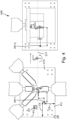
1 zeigt eine schematische schrägperspektivische Ansicht einer Umformanlage zum Herstellen komplex gestalteter Formteile aus Draht oder Rohr gemäß einem Ausführungsbeispiel; -
2 zeigt ein Detailder Umformmaschine aus 1 ; -
3 zeigt ein anderes Detailder Umformmaschine aus 1 ; und -
4 zeigt ein Detail einer Umformmaschine gemäß einem anderen Ausführungsbeispiel mit einer Biegestation und einer Pressenstation.
-
1 shows a schematic oblique perspective view of a forming system for producing complex shaped parts from wire or tube according to an embodiment; -
2 shows a detail of the forming machine from1 ; -
3 shows another detail of the forming machine from1 ; and -
4 shows a detail of a forming machine according to another embodiment with a bending station and a press station.
DETAILLIERTE BESCHREIBUNG DER AUSFÜHRUNGSBEISPIELEDETAILED DESCRIPTION OF THE EMBODIMENTS
Die
Das metallische Ausgangsmaterial W (Draht oder Rohr) liegt in Form eines nicht dargestellten aufgewickelten Materialvorrats (coil) vor. Die Umformanlage umfasst eine Konfektioniermaschine 200 zur Herstellung von gerade gerichteten Werkstücken WS vorgebbarer Länge aus dem zunächst noch gekrümmten Ausgangsmaterial sowie eine der Konfektioniermaschine 200 nachgeschaltete Umformmaschine 300 zum Herstellen komplex gebogener und/oder auf andere Weise in ihrer Gestalt gezielt veränderte Umformteile aus den geraden Werkstücken.The metallic starting material W (wire or tube) is in the form of a coiled material supply (not shown). The forming system comprises a finishing
Die Konfektioniermaschine weist eine Einzugseinrichtung 270 zum Einziehen von Werkstückmaterial von dem aufgewickelten Materialvorrat, eine Richteinrichtung 275 zum Richten des Werkstückmaterials W sowie eine nachgeschaltete Schnitteinrichtung 280 zum Abtrennen von gerichteten Werkstückabschnitten WS vom zugeführten Werkstückmaterial auf.The assembly machine comprises a
Unmittelbar bei der Schnitteinrichtung 280 findet die Übergabe der abgetrennten geraden Werkstücke zur nachgeschalteten Umformmaschine 300 statt. Dort befindet sich die Ladestation 400 der Umformmaschine.Directly at the
Die Umformmaschine 300 hat ein verwindungssteifes Maschinengestell 310, das eine vertikale Montagewand 312 umfasst, deren vertikale Vorderseite 313 parallel zur x-z-Ebene des Maschinenkoordinatensystems MKS liegt. Die horizontale y-Richtung verläuft senkrecht zur Vorderseite 313. An der Vorderseite sind flexibel nutzbare Montagestrukturen mit einer Vielzahl von mit Abstand übereinander angeordneten, horizontalen Montagenuten 314 mit T-Profil ausgebildet. Diese erlauben es, an jeder beliebigen Position in der x-Richtung Komponenten der Umformmaschine anzubringen, insbesondere die Komponenten von werkzeugtragenden Bearbeitungseinheiten, die die Arbeitsstationen der Mehrstationen-Umformmaschine bilden sollen. Zusätzlich zu den horizontalen Montagenuten können Montagebohrungen und andere Strukturen zur Befestigung von Komponenten vorliegen. Die horizontale x-Richtung wird hier auch als Längsrichtung bezeichnet, die horizontale y-Richtung als Querrichtung und die z-Richtung als Höhenrichtung.The forming
Die Umformmaschine 300 hat in der dargestellten Ausbaustufe vier Arbeitsstationen, nämlich die Ladestation 400, die bei der Schnitteinrichtung 280 liegt, sowie drei in horizontaler Reihe aufeinanderfolgende Umformstationen, nämlich eine erste Umformstation 410, eine zweite Umformstation 420 und eine dritte Umformstation 430.In the illustrated configuration, the forming
Die erste Umformstation 410 ist als Biegestation zum Biegen des Werkstücks ausgebildet. Sie weist dazu vier Arbeitseinheiten 412-1, 412-2, 412-3, 412-4 auf, die jeweils einen mittels eines Servomotors linear verfahrbaren Schieber umfassen. Die vertikal übereinander angeordneten und vertikal verfahrbaren Schieber 412-1 und 412-2 tragen jeweils an ihren Vorderseiten je ein Klemmwerkzeug zum Einklemmen bzw. Einspannen des Werkstücks WS in einer gewünschten räumlichen Lage. Das Werkzeug des unteren Schiebers 412-2 dient als Gegenelement zu den Biegeschiebern und gibt Teile der resultierenden Form vor. Die beiden schräg von oben zustellbaren Arbeitseinheiten 412-3, 412-4 tragen an ihren Vorderseiten Biegewerkzeuge, die in einem Arbeitshub am eingespannten Werkstück angreifen und dadurch Biegungen am Werkstück erzeugen.The first forming
Die zweite Umformstation 420 ist mit drei oberhalb der Transportstrecke angeordneten, parallel zueinander ausgerichteten Arbeitseinheiten 425-1, 425-2, 425-3 mit linear verfahrbaren Biegeschiebern ausgestattet, die es erlauben, die dort ankommenden, bereits gebogenen Werkstücke mittels Biegeschiebern zu biegen. Das Werkzeug des unteren Schiebers 412-4 dient als Gegenelement zu den Biegeschiebern und gibt Teile der resultierenden Form vor.The second forming
An der dritten Umformstation 430 sind drei in Winkeln zueinander angeordnete Biegeschieber angebracht. Zusätzlich ist noch ein von unten zustellbares Gegenwerkzeuge angebracht, das als Gegenelement zu den Biegeschiebern dient und Teile der resultierenden Form vorgibt.At the third forming
Die Arbeitseinheiten (z.B. Biegeschieber) der einzelnen Arbeitsstationen können variabel verfahren werden. Beispielsweise können sie gekoppelt oder voneinander getrennt verfahren und dabei kraftgesteuert, positionsgesteuert oder weggesteuert betrieben werden.The work units (e.g., bending slides) of the individual workstations can be moved variably. For example, they can be moved coupled or separately and operated force-controlled, position-controlled, or displacement-controlled.
Die Arbeitseinheiten einer Arbeitsstation sind nicht direkt bzw. unmittelbar an der Montagewand 312 montiert, sondern mittelbar unter Zwischenschaltung eines gemeinsamen Grundträgers. Das wird beispielhaft anhand der ersten Arbeitsstation 410 erläutert.The work units of a workstation are not mounted directly or immediately on the mounting
Alle Arbeitseinheiten 412-1 bis 412-4 der ersten Arbeitsstation 410 sind an der Vorderseite eines gemeinsamen plattenförmigen Grundträgers 415 montiert, der hier auch als Werkzeugträgerplatte 415 bezeichnet wird. An der gegenüberliegenden Rückseite des Grundträgers 415 sind die zu den Montagestrukturen der Montagewand 312 passenden Befestigungselemente angebracht.All work units 412-1 to 412-4 of the
Der Grundträger 415 und die davon getragenen Arbeitseinheiten 412-1 bis 412-4 werden vor der Befestigung an der Montagewand komplett vormontiert und eingerichtet und bilden dann ein erstes Werkzeugmodul 450-1, das als Ganzes an der Montagewand montiert wird. Der Grundträger 415 definiert ein trägerfestes Werkzeug-Koordinatensystem WKS. Alle werkzeugtragenden Arbeitseinheiten des Werkzeugmoduls sind mit Bezug auf einen gemeinsamen Referenzpunkt RP-1 im trägerfesten bzw. modulfesten Werkzeug-Koordinatensystem eingerichtet (vgl.
Zum Transfer bzw. Transport der Werkstücke zwischen den Arbeitsstationen weist die Umformmaschine ein Transportsystem 500 auf. Dieses ist modular aufgebaut und umfasst im dargestellten Beispielsfall vier Transportmodule 550-1, 550-2, 550-3 und 550-4. Jedes der Transportmodule ist eine gesondert vormontierte Baugruppe, die z.B. über eine Tragekonsole an der Vorderseite der Montagewand oder unabhängig von der Montagewand 310 montiert werden kann.For transferring or transporting the workpieces between the workstations, the forming machine has a
Alle Transportmodule sind nominell identisch oder weitgehend identisch aufgebaut und sorgen gemeinsam für einen sukzessiven Transfer aufeinanderfolgender Werkstücke von der Ladestation 400 zu allen drei nachfolgenden Bearbeitungsstationen und danach zu einem Abtransport. Diese Haupt-Transportrichtung verläuft in x-Richtung.All transport modules are nominally identical or largely identical in design and together ensure the successive transfer of consecutive workpieces from loading
Das erste Transportmodul 550-1 ist für den Transport von abgeschnittenen geraden Werkstücken zwischen Ladestation 400 bzw. Schnitteinrichtung 280 und erster Arbeitsstation bzw. Umformstation 410 vorgesehen. Das zweite Transportmodul 550-2 sorgt für den Transport zwischen erster Umformstation 410 und zweiter Umformstation 420 u.s.w..The first transport module 550-1 is intended for transporting cut straight workpieces between the
Am Beispiel des zweiten Transportmoduls 550-2 wird dessen Aufbau näher erläutert (vgl.
Jede Tragestruktur trägt eine einzige Transporteinheit 520, die mittels eines Schlittens 521 auf zwei an der Oberseite der Tragestruktur angebrachten Führungsschienen in x-Richtung verschiebbar geführt ist. Zum Bewegen der Transporteinheit 520 in x-Richtung (Haupt-Transportrichtung) ist ein Modul-eigenes Antriebssystem vorgesehen, das einen Transportantrieb 530 umfasst, der im Beispielsfall als Servomotor mit vertikaler Drehachse ausgebildet ist und an einem Ende der Tragestruktur montiert ist. Der Servomotor treibt einen horizontal umlaufenden Zahnriemen 524 an, der in den axialen Endbereichen der Tragestruktur über Umlenkrollen geführt ist. Der Schlitten ist am Zahnriemen befestigt und kann mithilfe des Transportantriebs 530 zwischen einem dem Transportantrieb 530 nächsten ersten Ende 521-1 und einem am weitesten davon entfernten zweiten Ende 521-2 im Pendelbetrieb hin- und her bewegt werden. Die Strecke zwischen den Enden 521-1 und 521-2 wird hier als Modul-Transportstreckte bezeichnet und entspricht dem maximalen Hub der Pendelbewegung in x-Richtung. Mithilfe dieses Antriebskonzepts können auch Pendelbewegungen mit kürzerem Pendelhub in x-Richtung realisiert werden.Each support structure carries a
Eine Pendelbewegung muss nicht über die gesamte Modul-Transportstrecke verlaufen. Der Pendelhub der tatsächlich genutzten Pendelbewegung verläuft zwischen einer ersten Endposition der Pendelbewegung und der gegenüberliegenden zweiten Endposition der Pendelbewegung.A pendulum movement does not have to cover the entire module transport path. The pendulum stroke of the actually used pendulum movement runs between a first end position of the pendulum movement and the opposite second end position of the pendulum movement.
Auf dem mithilfe des Transport-Antriebs 530 horizontal in x-Richtung verfahrbaren Schlitten 521 ist ein Grundträger 540 befestigt, der einen senkrecht zur Modul-Transportstrecke horizontal in y-Richtung verfahrbaren Greifarm 545 mit Rechteckprofil trägt. Dieser trägt an seinem der Vorderwand zugewandten Ende eine beispielsweise pneumatisch betätigbare mechanische Greifeinheit 560 zum Greifen eines Werkstücks. Die in y-Richtung laufende Horizontalbewegung (Querhub) des Greifarms wird mithilfe eines Antriebs 542 erzeugt, der am Grundträger der Transporteinheit 520 angebracht ist und mit diesem in x-Richtung verfahren kann. Eine Transporteinheit kann z.B. mithilfe einer geeignet dimensionierten einbaufertigen Linearachse in Form eines Omegamoduls aufgebaut werden.A
Bei manchen Varianten ist die Greifeinheit fest am horizontal verfahrbaren Greifarm montiert. Bei anderen Varianten ist die Greifeinheit mithilfe einer zwischen Greifeinheit und Greiferarm eingebauten Drehgruppe um 180° um eine in y-Richtung orientierte Greifeinheits-Drehachse drehbar. Der zusätzliche Aufbau bzw. die zusätzliche Länge dieser Einheit in y-Richtung kann durch den variablen Hub in y-Richtung kompensiert werden. Vorzugsweise sind die Greifarme gesteuert höhenverstellbar. Für die Funktionen Drehen und Heben/Senken kann jeweils z.B. ein pneumatischer oder servoelektrischer Antrieb vorgesehen sein. Die Bewegungen können über die Steuereinrichtung frei programmiert werden.In some variants, the gripping unit is permanently mounted on the horizontally movable gripper arm. In other variants, the gripping unit can be rotated 180° around a gripping unit rotation axis oriented in the y-direction using a rotating assembly installed between the gripping unit and the gripper arm. The additional structure or length of this unit in the y-direction can be compensated for by the variable stroke in the y-direction. The gripper arms are preferably height-adjustable. A pneumatic or servo-electric drive, for example, can be provided for the rotation and lifting/lowering functions. The movements can be freely programmed via the control unit.
Die Transportmodule sind in der horizontalen x-y-Ebene in zwei Reihen hintereinander angeordnet. Durch die zweireihige Anordnung mit Versatz in Haupt-Transportrichtung ergibt sich, dass die Transportstrecken unmittelbar aufeinanderfolgender Transportmodule im Bereich einer Arbeitsstation innerhalb eines Überlappungsbereichs überlappen. Die Länge des Überlappungsbereichs kann dabei bis zu fast der Hälfte der Länge der Modul-Transportstrecke betragen, so dass es vor jeder Arbeitsstation einen relativ breiten Bereich gibt, der sowohl von der Transporteinheit eines vorgeschalteten Transportmoduls als auch von der Transporteinheit des nachgeschalteten Transportmoduls angefahren werden kann.The transport modules are arranged in two rows, one behind the other, in the horizontal x-y plane. Due to the two-row arrangement with an offset in the main transport direction, the transport routes of immediately consecutive transport modules overlap within an overlap zone in the area of a workstation. The length of the overlap zone can be up to almost half the length of the module transport route, so that there is a relatively wide area in front of each workstation that can be accessed by both the transport unit of an upstream transport module and the transport unit of the downstream transport module.
Das modular aufgebaute Transportsystem 500 ist hinsichtlich der Manipulationsmöglichkeiten hochgradig flexibel. Der Hub in x-Richtung (Haupt-Transportrichtung bzw. Richtung der x-Pendelbewegung) ist an jeder Arbeitsstation unabhängig von den anderen Arbeitsstationen steuerbar. Gleiches gilt für den Hub in y-Richtung, die auch als Querrichtung bezeichnet wird und die Bewegung der Greifeinheiten zu den Arbeitsstationen hin und von diesen weg realisiert. Durch die gegenseitige Überlappung der Pendelhübe benachbarter Transporteinheiten ist in x-Richtung an jeder Arbeitsstation ein Überhub möglich. Es besteht auch die Möglichkeit, eine Arbeitsstation von zwei unterschiedlichen Seiten (in x-Richtung) zu bedienen.The
Bei jedem Transportmodul kann deren Greifeinheit 560 aufgrund der separaten Antriebe für den x-Hub und den y-Hub unabhängig von den Greifeinheiten der anderen Transportmodule flexibel in x-Richtung und y-Richtung verfahren werden. Damit ergibt sich u.a. eine hohe Flexibilität für die Teilung zwischen den Arbeitsstationen. Als „Teilung“ wird hier der in x-Richtung gemessene Abstand zwischen benachbarten Arbeitsstationen bzw. deren Werkstückhalteeinrichtungen bezeichnet.Thanks to the separate drives for the x-stroke and y-stroke, each transport module's
Das Konzept ist nicht nur hinsichtlich unterschiedlicher Abstände zwischen Arbeitsstationen hoch flexibel. Die Montagewand kann auch ein oder mehrere Module ergänzt werden. Dann können bei Bedarf weitere Transportmodule angebracht werden.The concept is not only highly flexible in terms of varying distances between workstations, but the assembly wall can also be expanded with one or more modules. Additional transport modules can then be attached as needed.
Die Umformmaschine ist bezüglich der x-Position der einzelnen Arbeitsstationen hochflexibel, so dass sie optimal auf die Abfolge und Art von Prozessschritten eines Umformprozesses abgestellt werden kann. Allerdings würde normalerweise relativ viel Zeit benötigt, um die Umformmaschine nach Montage der Werkzeugmodule so genau einzurichten, dass die Werkstücke mithilfe der Transporteinheit 520 exakt an die richtige Ablegeposition beziehungsweise Einlegeposition der von der Transporteinheit bedienten Arbeitsstation abgelegt und dann auch an der richtigen Stelle wieder gegriffen werden, um weitertransportiert zu werden. Erfolgt dies nicht präzise genug, so kann es zu Störungen im Betriebsablauf und/oder zu nicht mehr akzeptablen Fehlern in der Formteilgeometrie führen.The forming machine is highly flexible with regard to the x-position of the individual workstations, allowing it to be optimally adapted to the sequence and type of process steps of a forming process. However, it would normally require a relatively long time to set up the forming machine after assembly of the tool modules so precisely that the workpieces are placed precisely in the correct depositing or insertion position of the workstation served by the transport unit using the
Um hier Abhilfe zu schaffen, wird ein Koordinatenabgleichsystem zum Abgleichen von Koordinaten zwischen dem der Transporteinheit 520 zugeordneten Transport-Koordinatensystem TKS und dem einer jeweiligen Arbeitsstation oder einem Werkzeugmodul zugeordneten Werkzeug-Koordinatensystem WKS bereitgestellt. Mithilfe des Koordinatenabgleichsystems können Koordinatentransformationsdaten ermittelt werden, die von der Steuereinheit 190 im produktiven Betrieb dazu genutzt werden können, jede der Transporteinheiten 520 bzw. deren Greifeinheiten exakt so zu steuern, dass eine Greifeinheit der Transporteinheiten positionsgenau auf eine im Werkzeug-Koordinatensystem vorgebbare Zielposition gesteuert werden kann, also beispielsweise diejenige Position, die die Greifeinheit beim Antransport eines Werkstücks erreichen soll (Ablageposition) und/oder diejenige Position, zu der die Greifeinheit fahren muss, um das Werkstück nach Abschluss der an einer Arbeitsstation vorzunehmenden Operation zu greifen und danach weiter zu transportieren. Dies wird anhand der
Das Koordinatenabgleichsystem umfasst Komponenten, die den einzelnen Arbeitseinheiten zugeordnet sind, sowie Komponenten, die dem Transportsystem bzw. den einzelnen Transporteinheiten mit deren Greifeinheiten zugeordnet sind.The coordinate alignment system includes components that are assigned to the individual work units, as well as components that are assigned to the transport system or the individual transport units with their gripping units.
Die Arbeitseinheiten sind nach Befestigung auf der Werkzeugträgerplatte in Bezug zu dieser Werkzeugträgerplatte und in Bezug relativ zueinander bezüglich eines Referenzpunkts RP-1 eingerichtet worden, so dass das Werkzeugmodul in sich komplett eingerichtet war, bevor es an der Montagewand 310 befestigt wurde. Der Referenzpunkt RP-1 hat bezüglich des Werkzeug-Koordinatensystems WKS bekannte Koordinaten, wobei hier in der Regel nur die Koordinaten in x-Richtung (Haupttransportrichtung) und in z-Richtung (Vertikalrichtung) interessieren.After being mounted on the tool carrier plate, the work units were aligned relative to this tool carrier plate and relative to each other with respect to a reference point RP-1, so that the tool module was completely aligned before being mounted on the mounting
Die vorgeschaltete Schnitteinrichtung 280 hat einen entsprechenden Referenzpunkt RP-0 in Bezug auf das Werkzeug-Koordinatensystem. Mit Bezugszeichen 560 ist die Greifeinheit der Transporteinheit des ersten Transportmoduls 550-1 bezeichnet, das für den Transport des vom Drahtvorrat abgeschnittenen Werkstücks WS von der Ladestation 400 beziehungsweise der Schnitteinrichtung zur ersten Arbeitsstation zuständig ist. Um diesen Transport zielgenau zu bewerkstelligen, muss die Greifeinheit an einer exakt vorgebbaren Stelle im vorderen Werkstückbereich angreifen, bevor das gerade Werkstück WS vom zugeführten Draht abgetrennt wird. Dann wird das Werkstück mithilfe der linear verfahrbaren Transporteinheit 520 parallel zur Drahtzuführrichtung bzw. zur Maschinenmittellinie 317 und zur x-Richtung in Richtung der ersten Arbeitsstation 410 transportiert und dabei geringfügig nach oben abgehoben, so dass es im Bereich der ersten Arbeitsstation 410 bezüglich Höhenrichtung und Haupttransportrichtung genau so positioniert werden kann, dass die auf den Referenzpunkt RP-1 eingerichteten Arbeitseinheiten die Biegungen genau an den vorgesehenen Abschnitten des noch geraden Werkstücks einbringen können. Dazu wird das Werkstück WS in seine Bearbeitungsposition im Eingriffsbereich der Arbeitseinheiten der ersten Arbeitsstation nach vorn transportiert. Dann werden die vertikalen Schieber der Arbeitseinheiten 412-1, 412-2 in Richtung Werkstück zugestellt, bis das Werkstück dazwischen eingeklemmt ist. Dann wird der Greifer 560 der ersten Transporteinheit geöffnet und in y-Richtung zurückgefahren. Danach findet die Umformoperation beziehungsweise Biegeoperation durch Zustellen der schräg gestellten Arbeitseinheiten statt.The
Danach soll das umgeformte Werkstück mithilfe der zweiten Transporteinheit in Richtung der nachfolgenden zweiten Arbeitsstation 420 transportiert werden. Dazu ist gemäß dem Prozess vorgesehen, dass die Greifeinheit 560-2 der zweiten Transporteinheit das gebogene Werkstück an einer genau vorgegebenen Stelle (Abholposition) greift, durch einen Y-Hub aus dem Arbeitsbereich der Arbeitseinheiten bewegt und danach in z-Richtung zur nachfolgenden Arbeitsstation weitertransportiert.The formed workpiece is then to be transported by means of the second transport unit toward the subsequent
Um diese Arbeitsoperation des Transportsystems lagegenau durchführen zu können, muss die Steuereinheit 190 wissen, zu welchen Positionen in dem Transport-Koordinatensystem die Transporteinheiten beziehungsweise deren Greifeinheiten verfahren werden müssen, um die angestrebte Zielposition im Werkzeug-Koordinatensystem zu erreichen.In order to be able to carry out this work operation of the transport system with precise positioning, the
Hierzu wird in einer Einrichtoperation mithilfe der Komponenten des Koordinatenabgleichsystems eine Koordinatenabgleich-Operation durchgeführt. Hierzu wird im Beispielsfall auf den horizontal verfahrbaren Arm der ersten Transporteinheit 520-1 eine taktil arbeitende Antasteinrichtung 610 montiert, die eine Tastspitze aufweist, deren Position im Transport-Koordinatensystem bekannt ist. Mithilfe dieser Tastspitze wird zunächst die vertikale Vorderkante KV und danach die horizontal ausgerichtete Unterkante KU der Werkzeugträgerplatte 415 angetastet. Es kann auch mit umgekehrter Reihenfolge angetastet werden. Durch die Antastoperation sind die x-Koordinate der Vorderkante und die z-Koordinate der Unterkante im Transport-Koordinatensystem bekannt.For this purpose, a coordinate alignment operation is performed in a setup operation using the components of the coordinate alignment system. In the example case, a tactile probing
Die für die Antastung vorgesehenen Kanten der Werkzeugträgerplatte dienen als antastbare Hilfsstruktur am Werkzeugmodul. Sie definieren einen Hilfsnullpunkt HP, der hier z.B. auf der Ecke liegt, an der die angetasteten Kanten einander treffen. Die relative Lage der Kanten zum Referenzpunkt RP kann durch den Versatz VX in x-Richtung in Bezug auf die Vorderkante KV sowie den Versatz VZ zur antastbaren Unterkante angegeben werden.The edges of the tool carrier plate intended for probing serve as a probable auxiliary structure on the tool module. They define an auxiliary zero point HP, which in this case, for example, is located at the corner where the probing edges meet. The relative position of the edges to the reference point RP can be specified by the offset VX in the x-direction with respect to the leading edge KV and the offset VZ with respect to the probable lower edge.
Statt die Kanten einer Werkzeugträgerplatte einzeln anzufahren, wäre es auch möglich, dass der taktile Messtaster eine definierte Bohrung in oder an der Werkzeugträgerplatte anfährt. Hier dient dann die Bohrung als Hilfsstruktur.Instead of approaching the edges of a tool carrier plate individually, it would also be possible for the tactile measuring probe to approach a defined hole in or on the tool carrier plate. The hole then serves as an auxiliary structure.
Mithilfe dieser Versatzdaten ist es nun möglich, das Werkzeug-Koordinatensystem WKS und das Transport-Koordinatensystem TKS miteinander abzugleichen. Beispielsweise ergibt sich die x-Position des Referenzpunkts RP aus der Summe der Koordinaten der Vorderkante KV im Transport-Koordinatensystem und dem Versatz VX zwischen der Vorderkante und dem Referenzpunkt.Using this offset data, it is now possible to align the tool coordinate system (WKS) and the transport coordinate system (TKS). For example, the x-position of the reference point (RP) results from the sum of the coordinates of the leading edge (KV) in the transport coordinate system and the offset (VX) between the leading edge and the reference point.
Um es der Steuereinheit zu ermöglichen, die Bewegungen der Transporteinheit unter Verwendung der Versatzdaten so zu steuern, dass im Werkzeug-Koordinatensystem exakt definierbare Zielpositionen genau angefahren werden können, benötigt die Steuereinheit neben denjenigen Angaben, die sich durch Antasten von Hilfsstrukturen am Werkzeugmodul ergeben, auch die Versatzdaten.In order to enable the control unit to control the movements of the transport unit using the offset data in such a way that precisely definable target positions in the tool coordinate system can be approached precisely, the control unit requires the offset data in addition to the information obtained by probing auxiliary structures on the tool module.
Bei einer Ausführungsform sind die Versatzdaten codiert in einem optisch auslesbaren Datenträger DT am Werkzeugmodul enthalten. Beispielsweise kann dort ein QR-Code aufgeklebt oder auf andere Weise angeordnet sein. An der Transporteinheit 520-1 oder 520-2 kann ein QR-Scanner oder eine Kamera montiert sein, die Bilddaten an die Steuereinheit 190 liefert. Diese kann Decodiersoftware enthalten, um die im QR-Code codierten Versatzdaten zu ermitteln und in einem Speicher abzulegen. Die Versatzdaten können auch in Klartext angegeben und durch eine Kamera an der Transporteinheit erfasst und mittels Bildverarbeitung (Texterkennung) in speicherbare Versatzdaten gewandelt werden. Alternativ könnte auch ein RFID-Chip als Datenträger genutzt werden, der mittels eines an der Transporteinheit montierten Lesekopfs ausgelesen werden könnte.In one embodiment, the offset data is encoded in an optically readable data carrier DT on the tool module. For example, a QR code can be affixed there or arranged in some other way. A QR scanner or camera can be mounted on the transport unit 520-1 or 520-2, which delivers image data to the
Auf diesen Speicher kann die Steuereinheit 190 bei der späteren Steuerung im produktiven Betrieb zurückgreifen. In analoger Weise können bei allen Arbeitsstationen die beiden Koordinatensysteme (Werkzeug-Koordinatensystem und Transport-Koordinatensystem) miteinander abgeglichen werden.The
Als ein weiteres Beispiel zeigt
Die Ausstattung der Umformmaschine ist nur ein Beispiel. Zusätzlich zu zwei oder mehr Umformstationen können noch andere Bearbeitungsstationen und/oder andere Arbeitsstationen vorgesehen sein. Beispielsweise kann es sein, dass am zu erzeugenden Formteil ein Abschnitt mit Gewinde, Rillen, Rändel oder Ähnlichem zu fertigen ist. Die Erzeugung eines Gewindes kann beispielsweise mit einer Flachbackenwalze geschehen, die z.B. zwischen der Schnittvorrichtung 280 und der ersten Umformbearbeitung an der ersten Umformstation 410 angeordnet sein kann. Eine Gewindeherstellung mittels eines Rollierkopfs kann am Ende der Operation, also hinter der dritten Umformeinheit 430, vorgesehen sein. Bei Bedarf kann auch eine spanende Bearbeitung am abgetrennten Werkstück vorgenommen werden, beispielsweise durch Anfasen, Planieren oder Anspitzen. Eine entsprechende spanende Bearbeitungsstation kann beispielsweise zwischen der Schnittvorrichtung 280 und der ersten Umformstation 410 angeordnet sein, damit die spanende Bearbeitung am noch geraden Werkstück durchgeführt werden kann. Mindestens eine Arbeitsstation kann bei Bedarf eine CNC-Presse aufweisen, beispielsweise um an einem Formteil aus Rundmaterial einen abgeflachten Abschnitt zu erzeugen. Es kann auch eine Messstation vorgesehen sein, z.B. um die Geometrie des gemessenen Formteils mittels einer Kamera und Bildverarbeitung optisch zu bestimmen.The equipment of the forming machine is only one example. In addition to two or more forming stations, other processing stations and/or other workstations may be provided. For example, a section with a thread, grooves, knurl, or the like may be required on the molded part to be produced. A thread can be produced, for example, using a flat-jaw roller, which can be arranged, for example, between the cutting
ZITATE ENTHALTEN IN DER BESCHREIBUNGQUOTES CONTAINED IN THE DESCRIPTION
Diese Liste der vom Anmelder aufgeführten Dokumente wurde automatisiert erzeugt und ist ausschließlich zur besseren Information des Lesers aufgenommen. Die Liste ist nicht Bestandteil der deutschen Patent- bzw. Gebrauchsmusteranmeldung. Das DPMA übernimmt keinerlei Haftung für etwaige Fehler oder Auslassungen.This list of documents submitted by the applicant was generated automatically and is included solely for the convenience of the reader. This list is not part of the German patent or utility model application. The DPMA assumes no liability for any errors or omissions.
Zitierte PatentliteraturCited patent literature
- US 2005/145003A1 [0005]US 2005/145003A1 [0005]
Claims (13)
Priority Applications (2)
| Application Number | Priority Date | Filing Date | Title |
|---|---|---|---|
| DE102023136070.1A DE102023136070A1 (en) | 2023-12-20 | 2023-12-20 | Forming machine with multiple workstations |
| PCT/EP2024/084644 WO2025131716A1 (en) | 2023-12-20 | 2024-12-04 | Forming machine comprising a plurality of workstations |
Applications Claiming Priority (1)
| Application Number | Priority Date | Filing Date | Title |
|---|---|---|---|
| DE102023136070.1A DE102023136070A1 (en) | 2023-12-20 | 2023-12-20 | Forming machine with multiple workstations |
Publications (1)
| Publication Number | Publication Date |
|---|---|
| DE102023136070A1 true DE102023136070A1 (en) | 2025-06-26 |
Family
ID=93840680
Family Applications (1)
| Application Number | Title | Priority Date | Filing Date |
|---|---|---|---|
| DE102023136070.1A Pending DE102023136070A1 (en) | 2023-12-20 | 2023-12-20 | Forming machine with multiple workstations |
Country Status (2)
| Country | Link |
|---|---|
| DE (1) | DE102023136070A1 (en) |
| WO (1) | WO2025131716A1 (en) |
Citations (4)
| Publication number | Priority date | Publication date | Assignee | Title |
|---|---|---|---|---|
| JPS59177607A (en) * | 1983-03-28 | 1984-10-08 | Fanuc Ltd | Automatic programming method |
| US20050145003A1 (en) * | 2004-01-07 | 2005-07-07 | David Burton | Bending system |
| JP2011048467A (en) * | 2009-08-25 | 2011-03-10 | Fanuc Ltd | Machining system |
| DE102015015094B4 (en) * | 2014-11-28 | 2018-11-15 | Fanuc Corporation | Cooperation system with machine tool and robot |
Family Cites Families (2)
| Publication number | Priority date | Publication date | Assignee | Title |
|---|---|---|---|---|
| DE102018221152A1 (en) * | 2018-12-06 | 2020-06-10 | Otto Bihler Handels-Beteiligungs-Gmbh | MACHINE FOR PRODUCING WIRE ELEMENTS |
| DE102022204106A1 (en) * | 2022-04-27 | 2023-11-02 | Wafios Aktiengesellschaft | Bending machine and wire processing system with bending machine |
-
2023
- 2023-12-20 DE DE102023136070.1A patent/DE102023136070A1/en active Pending
-
2024
- 2024-12-04 WO PCT/EP2024/084644 patent/WO2025131716A1/en active Pending
Patent Citations (4)
| Publication number | Priority date | Publication date | Assignee | Title |
|---|---|---|---|---|
| JPS59177607A (en) * | 1983-03-28 | 1984-10-08 | Fanuc Ltd | Automatic programming method |
| US20050145003A1 (en) * | 2004-01-07 | 2005-07-07 | David Burton | Bending system |
| JP2011048467A (en) * | 2009-08-25 | 2011-03-10 | Fanuc Ltd | Machining system |
| DE102015015094B4 (en) * | 2014-11-28 | 2018-11-15 | Fanuc Corporation | Cooperation system with machine tool and robot |
Also Published As
| Publication number | Publication date |
|---|---|
| WO2025131716A1 (en) | 2025-06-26 |
Similar Documents
| Publication | Publication Date | Title |
|---|---|---|
| EP3463708B1 (en) | Tool storage system, production plant and method for manipulating with such a tool storage system | |
| AT519014B1 (en) | Production plant with manipulation device | |
| EP2670543A1 (en) | Production device with means for tool position sensing and method for operating said device | |
| WO2009024246A1 (en) | Packer head | |
| AT509980B1 (en) | MANUFACTURING SYSTEM WITH TOOL MEMORY | |
| DE102012109245B3 (en) | Method and device for machining non-rotationally symmetrical workpieces by means of laser radiation | |
| EP4225515A1 (en) | Bending machine, and wire-processing system comprising a bending machine | |
| DE69430148T2 (en) | Table for determining the position of a workpiece made of sheet metal in a system for producing folded sheet metal articles | |
| DE69124889T2 (en) | Versatile automatic machine for processing metal strips | |
| DE2533609B2 (en) | Device for automatically soldering wires in pairs on contact positions of circuit cards and similar circuit carriers | |
| EP4295968A1 (en) | Forming machine with multiple work stations | |
| DE60219267T2 (en) | Gripping unit for the automated machining of workpieces, and apparatus and method with such a unit | |
| AT522991A1 (en) | Process for the transport and / or handling of components | |
| EP0967038B1 (en) | Device for machining by material removal of workpieces | |
| EP3031572A1 (en) | Tool exchange apparatus for use in a machining centre and machining centre for machining a workpiece | |
| EP2198991A1 (en) | Sheet mtal loading and unloading unit with a tool holder for sheet metal processing machines | |
| EP1002594A2 (en) | Method and device for forming a workpiece | |
| DE102022204106A1 (en) | Bending machine and wire processing system with bending machine | |
| AT504171B1 (en) | METHOD FOR LOADING AND UNLOADING A TOOLING MACHINE WITH TOOLS | |
| DE102023136070A1 (en) | Forming machine with multiple workstations | |
| AT519221B1 (en) | Production plant with a clamping tool and method for adjusting a total length of a bending edge of the clamping tool | |
| EP4166864B1 (en) | Method and assembly device for automated assembly of a frame for an air duct element | |
| EP3292949B1 (en) | Method for mutual positioning of storage units of a workpiece storage, workpiece storage, machine tool with a workpiece storage and control program | |
| DE102019218038B4 (en) | Honing machine with several work stations and production facility | |
| DE102020108037A1 (en) | Tooling for holding workpieces |
Legal Events
| Date | Code | Title | Description |
|---|---|---|---|
| R012 | Request for examination validly filed |