DE102023135327A1 - Device with holographic marking, master plate for producing such a device, and corresponding methods - Google Patents
Device with holographic marking, master plate for producing such a device, and corresponding methods Download PDFInfo
- Publication number
- DE102023135327A1 DE102023135327A1 DE102023135327.6A DE102023135327A DE102023135327A1 DE 102023135327 A1 DE102023135327 A1 DE 102023135327A1 DE 102023135327 A DE102023135327 A DE 102023135327A DE 102023135327 A1 DE102023135327 A1 DE 102023135327A1
- Authority
- DE
- Germany
- Prior art keywords
- holographic
- marking
- hologram
- light
- master plate
- Prior art date
- Legal status (The legal status is an assumption and is not a legal conclusion. Google has not performed a legal analysis and makes no representation as to the accuracy of the status listed.)
- Pending
Links
Images


Classifications
-
- G—PHYSICS
- G03—PHOTOGRAPHY; CINEMATOGRAPHY; ANALOGOUS TECHNIQUES USING WAVES OTHER THAN OPTICAL WAVES; ELECTROGRAPHY; HOLOGRAPHY
- G03H—HOLOGRAPHIC PROCESSES OR APPARATUS
- G03H1/00—Holographic processes or apparatus using light, infrared or ultraviolet waves for obtaining holograms or for obtaining an image from them; Details peculiar thereto
- G03H1/02—Details of features involved during the holographic process; Replication of holograms without interference recording
-
- B—PERFORMING OPERATIONS; TRANSPORTING
- B60—VEHICLES IN GENERAL
- B60K—ARRANGEMENT OR MOUNTING OF PROPULSION UNITS OR OF TRANSMISSIONS IN VEHICLES; ARRANGEMENT OR MOUNTING OF PLURAL DIVERSE PRIME-MOVERS IN VEHICLES; AUXILIARY DRIVES FOR VEHICLES; INSTRUMENTATION OR DASHBOARDS FOR VEHICLES; ARRANGEMENTS IN CONNECTION WITH COOLING, AIR INTAKE, GAS EXHAUST OR FUEL SUPPLY OF PROPULSION UNITS IN VEHICLES
- B60K35/00—Instruments specially adapted for vehicles; Arrangement of instruments in or on vehicles
- B60K35/20—Output arrangements, i.e. from vehicle to user, associated with vehicle functions or specially adapted therefor
- B60K35/21—Output arrangements, i.e. from vehicle to user, associated with vehicle functions or specially adapted therefor using visual output, e.g. blinking lights or matrix displays
- B60K35/23—Head-up displays [HUD]
-
- G—PHYSICS
- G03—PHOTOGRAPHY; CINEMATOGRAPHY; ANALOGOUS TECHNIQUES USING WAVES OTHER THAN OPTICAL WAVES; ELECTROGRAPHY; HOLOGRAPHY
- G03H—HOLOGRAPHIC PROCESSES OR APPARATUS
- G03H1/00—Holographic processes or apparatus using light, infrared or ultraviolet waves for obtaining holograms or for obtaining an image from them; Details peculiar thereto
- G03H1/04—Processes or apparatus for producing holograms
- G03H1/20—Copying holograms by holographic, i.e. optical means
- G03H1/202—Contact copy when the reconstruction beam for the master H1 also serves as reference beam for the copy H2
-
- G—PHYSICS
- G03—PHOTOGRAPHY; CINEMATOGRAPHY; ANALOGOUS TECHNIQUES USING WAVES OTHER THAN OPTICAL WAVES; ELECTROGRAPHY; HOLOGRAPHY
- G03H—HOLOGRAPHIC PROCESSES OR APPARATUS
- G03H1/00—Holographic processes or apparatus using light, infrared or ultraviolet waves for obtaining holograms or for obtaining an image from them; Details peculiar thereto
- G03H1/22—Processes or apparatus for obtaining an optical image from holograms
- G03H1/2202—Reconstruction geometries or arrangements
-
- G—PHYSICS
- G03—PHOTOGRAPHY; CINEMATOGRAPHY; ANALOGOUS TECHNIQUES USING WAVES OTHER THAN OPTICAL WAVES; ELECTROGRAPHY; HOLOGRAPHY
- G03H—HOLOGRAPHIC PROCESSES OR APPARATUS
- G03H1/00—Holographic processes or apparatus using light, infrared or ultraviolet waves for obtaining holograms or for obtaining an image from them; Details peculiar thereto
- G03H1/22—Processes or apparatus for obtaining an optical image from holograms
- G03H1/2249—Holobject properties
-
- G—PHYSICS
- G03—PHOTOGRAPHY; CINEMATOGRAPHY; ANALOGOUS TECHNIQUES USING WAVES OTHER THAN OPTICAL WAVES; ELECTROGRAPHY; HOLOGRAPHY
- G03H—HOLOGRAPHIC PROCESSES OR APPARATUS
- G03H1/00—Holographic processes or apparatus using light, infrared or ultraviolet waves for obtaining holograms or for obtaining an image from them; Details peculiar thereto
- G03H1/26—Processes or apparatus specially adapted to produce multiple sub- holograms or to obtain images from them, e.g. multicolour technique
- G03H1/30—Processes or apparatus specially adapted to produce multiple sub- holograms or to obtain images from them, e.g. multicolour technique discrete holograms only
-
- B—PERFORMING OPERATIONS; TRANSPORTING
- B60—VEHICLES IN GENERAL
- B60K—ARRANGEMENT OR MOUNTING OF PROPULSION UNITS OR OF TRANSMISSIONS IN VEHICLES; ARRANGEMENT OR MOUNTING OF PLURAL DIVERSE PRIME-MOVERS IN VEHICLES; AUXILIARY DRIVES FOR VEHICLES; INSTRUMENTATION OR DASHBOARDS FOR VEHICLES; ARRANGEMENTS IN CONNECTION WITH COOLING, AIR INTAKE, GAS EXHAUST OR FUEL SUPPLY OF PROPULSION UNITS IN VEHICLES
- B60K2360/00—Indexing scheme associated with groups B60K35/00 or B60K37/00 relating to details of instruments or dashboards
- B60K2360/20—Optical features of instruments
- B60K2360/29—Holographic features
-
- G—PHYSICS
- G03—PHOTOGRAPHY; CINEMATOGRAPHY; ANALOGOUS TECHNIQUES USING WAVES OTHER THAN OPTICAL WAVES; ELECTROGRAPHY; HOLOGRAPHY
- G03H—HOLOGRAPHIC PROCESSES OR APPARATUS
- G03H1/00—Holographic processes or apparatus using light, infrared or ultraviolet waves for obtaining holograms or for obtaining an image from them; Details peculiar thereto
- G03H1/0005—Adaptation of holography to specific applications
- G03H1/0011—Adaptation of holography to specific applications for security or authentication
-
- G—PHYSICS
- G03—PHOTOGRAPHY; CINEMATOGRAPHY; ANALOGOUS TECHNIQUES USING WAVES OTHER THAN OPTICAL WAVES; ELECTROGRAPHY; HOLOGRAPHY
- G03H—HOLOGRAPHIC PROCESSES OR APPARATUS
- G03H1/00—Holographic processes or apparatus using light, infrared or ultraviolet waves for obtaining holograms or for obtaining an image from them; Details peculiar thereto
- G03H1/02—Details of features involved during the holographic process; Replication of holograms without interference recording
- G03H1/0236—Form or shape of the hologram when not registered to the substrate, e.g. trimming the hologram to alphanumerical shape
-
- G—PHYSICS
- G03—PHOTOGRAPHY; CINEMATOGRAPHY; ANALOGOUS TECHNIQUES USING WAVES OTHER THAN OPTICAL WAVES; ELECTROGRAPHY; HOLOGRAPHY
- G03H—HOLOGRAPHIC PROCESSES OR APPARATUS
- G03H1/00—Holographic processes or apparatus using light, infrared or ultraviolet waves for obtaining holograms or for obtaining an image from them; Details peculiar thereto
- G03H1/02—Details of features involved during the holographic process; Replication of holograms without interference recording
- G03H1/024—Hologram nature or properties
- G03H1/0248—Volume holograms
-
- G—PHYSICS
- G03—PHOTOGRAPHY; CINEMATOGRAPHY; ANALOGOUS TECHNIQUES USING WAVES OTHER THAN OPTICAL WAVES; ELECTROGRAPHY; HOLOGRAPHY
- G03H—HOLOGRAPHIC PROCESSES OR APPARATUS
- G03H1/00—Holographic processes or apparatus using light, infrared or ultraviolet waves for obtaining holograms or for obtaining an image from them; Details peculiar thereto
- G03H1/0005—Adaptation of holography to specific applications
- G03H1/0011—Adaptation of holography to specific applications for security or authentication
- G03H2001/0016—Covert holograms or holobjects requiring additional knowledge to be perceived, e.g. holobject reconstructed only under IR illumination
-
- G—PHYSICS
- G03—PHOTOGRAPHY; CINEMATOGRAPHY; ANALOGOUS TECHNIQUES USING WAVES OTHER THAN OPTICAL WAVES; ELECTROGRAPHY; HOLOGRAPHY
- G03H—HOLOGRAPHIC PROCESSES OR APPARATUS
- G03H1/00—Holographic processes or apparatus using light, infrared or ultraviolet waves for obtaining holograms or for obtaining an image from them; Details peculiar thereto
- G03H1/04—Processes or apparatus for producing holograms
- G03H1/0402—Recording geometries or arrangements
- G03H2001/0439—Recording geometries or arrangements for recording Holographic Optical Element [HOE]
-
- G—PHYSICS
- G03—PHOTOGRAPHY; CINEMATOGRAPHY; ANALOGOUS TECHNIQUES USING WAVES OTHER THAN OPTICAL WAVES; ELECTROGRAPHY; HOLOGRAPHY
- G03H—HOLOGRAPHIC PROCESSES OR APPARATUS
- G03H1/00—Holographic processes or apparatus using light, infrared or ultraviolet waves for obtaining holograms or for obtaining an image from them; Details peculiar thereto
- G03H1/04—Processes or apparatus for producing holograms
- G03H1/0465—Particular recording light; Beam shape or geometry
- G03H2001/0473—Particular illumination angle between object or reference beams and hologram
-
- G—PHYSICS
- G03—PHOTOGRAPHY; CINEMATOGRAPHY; ANALOGOUS TECHNIQUES USING WAVES OTHER THAN OPTICAL WAVES; ELECTROGRAPHY; HOLOGRAPHY
- G03H—HOLOGRAPHIC PROCESSES OR APPARATUS
- G03H1/00—Holographic processes or apparatus using light, infrared or ultraviolet waves for obtaining holograms or for obtaining an image from them; Details peculiar thereto
- G03H1/22—Processes or apparatus for obtaining an optical image from holograms
- G03H1/2202—Reconstruction geometries or arrangements
- G03H2001/2244—Means for detecting or recording the holobject
-
- G—PHYSICS
- G03—PHOTOGRAPHY; CINEMATOGRAPHY; ANALOGOUS TECHNIQUES USING WAVES OTHER THAN OPTICAL WAVES; ELECTROGRAPHY; HOLOGRAPHY
- G03H—HOLOGRAPHIC PROCESSES OR APPARATUS
- G03H2210/00—Object characteristics
- G03H2210/50—Nature of the object
- G03H2210/55—Having particular size, e.g. irresolvable by the eye
-
- G—PHYSICS
- G03—PHOTOGRAPHY; CINEMATOGRAPHY; ANALOGOUS TECHNIQUES USING WAVES OTHER THAN OPTICAL WAVES; ELECTROGRAPHY; HOLOGRAPHY
- G03H—HOLOGRAPHIC PROCESSES OR APPARATUS
- G03H2222/00—Light sources or light beam properties
- G03H2222/40—Particular irradiation beam not otherwise provided for
- G03H2222/46—Reconstruction beam at reconstruction stage
-
- G—PHYSICS
- G03—PHOTOGRAPHY; CINEMATOGRAPHY; ANALOGOUS TECHNIQUES USING WAVES OTHER THAN OPTICAL WAVES; ELECTROGRAPHY; HOLOGRAPHY
- G03H—HOLOGRAPHIC PROCESSES OR APPARATUS
- G03H2223/00—Optical components
- G03H2223/12—Amplitude mask, e.g. diaphragm, Louver filter
-
- G—PHYSICS
- G03—PHOTOGRAPHY; CINEMATOGRAPHY; ANALOGOUS TECHNIQUES USING WAVES OTHER THAN OPTICAL WAVES; ELECTROGRAPHY; HOLOGRAPHY
- G03H—HOLOGRAPHIC PROCESSES OR APPARATUS
- G03H2270/00—Substrate bearing the hologram
- G03H2270/20—Shape
- G03H2270/21—Curved bearing surface
Landscapes
- Physics & Mathematics (AREA)
- General Physics & Mathematics (AREA)
- Engineering & Computer Science (AREA)
- Chemical & Material Sciences (AREA)
- Combustion & Propulsion (AREA)
- Transportation (AREA)
- Mechanical Engineering (AREA)
- Holo Graphy (AREA)
Abstract
Es werden Vorrichtungen mit einem holografischen Material und einer in dem holografischen Material bereitgestellten holografischen Markierung (13) beschrieben. Die holografische Markierung (13) ist dabei nur sensitiv auf Licht einer vorgegebenen Wellenlänge und/oder auf Licht aus einer vorgegebenen Richtung, und/oder ist eingerichtet, Licht nur in eine weitere vorgegebene Richtung zu beugen. Die Vorrichtung kann weiter ein Haupthologramm (12) enthalten. Zudem werden entsprechende Masterplatten zur Herstellung derartiger Vorrichtungen, Verfahren und Herstellungsvorrichtungen beschrieben.

Description
Die vorliegende Anmeldung betrifft Vorrichtungen mit einer holografischen Markierung, Masterplatten zur Herstellung derartiger Vorrichtungen und entsprechende Verfahren.The present application relates to devices with a holographic marking, master plates for producing such devices and corresponding methods.
Bei verschiedenen Produkten, das heißt Vorrichtungen, kommen unterschiedliche Arten von Markierungen zum Einsatz. Dies können Markierungen sein, welche bei der Herstellung des Produktes benötigt werden, beispielsweise Justagemarken. Diese werden zur Ausrichtung und zur Positionierung im Verlauf einer Herstellung der Vorrichtung verwendet. Andere Beispiele sind Markierungen zur Rückverfolgbarkeit wie Artikelnummern, Batch-/Chargen-/LOT-Nummern, Seriennummern, oder UDI (unique device identifier; einmalige Produktkennung) -CodesDifferent types of markings are used for different products, i.e., devices. These can be markings required during product manufacturing, such as alignment marks. These are used for alignment and positioning during device manufacturing. Other examples are markings for traceability, such as article numbers, batch/lot numbers, serial numbers, or UDI (unique device identifier) codes.
Andere Beispiele umfassen Markenlogos, Qualitätssiegel, oder andere codierte Inhalte wie Prozessparameter oder Preis/Produktinformationen.Other examples include brand logos, quality seals, or other coded content such as process parameters or price/product information.
In manchen Anwendungsfällen wie beispielsweise bei Markenlogos oder Qualitätssiegeln, ist es gewünscht, dass die Markierungen sichtbar sind, in anderen Fällen können auch nicht ohne weiteres sichtbare Markierungen (insbesondere im Regelfall nicht durch einen Endverbraucher sichtbare Markierungen) wünschenswert sein.In some applications, such as brand logos or quality seals, it is desirable for the markings to be visible; in other cases, markings that are not readily visible (in particular, markings that are not normally visible to an end user) may be desirable.
Herkömmliche Markierungen werden auf die Vorrichtungen gedruckt, eingeprägt, gestanzt, mit einem Laser geschrieben oder mittels einer Klebeetikette aufgebracht. Auch thermische Verfahren sind möglich.Conventional markings are printed, embossed, punched, laser-etched, or applied to the devices using an adhesive label. Thermal processes are also possible.
Für manche Zwecke werden auch holografische Markierungen verwendet. Beispiele finden sich in der
Es ist eine Aufgabe, diesbezüglich verbesserte Möglichkeiten zu schaffen.It is a task to create improved opportunities in this regard.
Es werden eine Vorrichtung nach Anspruch 1, 2, 3 oder 6, eine Masterplatte nach Anspruch 10, ein Verfahren nach Anspruch 17 oder eine Herstellungsvorrichtung nach Anspruch 19 bereitgestellt. Die Unteransprüche definieren weitere Ausführungsformen.An apparatus according to
Generell umfasst eine Vorrichtung gemäß verschiedenen Aspekten ein holografisches Material und mindestens eine in dem holografischen Material bereitgestellte holografische Markierung. Bei einem ersten Aspekt weist das holografische Material zudem ein Haupthologramm auf. Ein Haupthologramm ist dabei ein Hologramm, welches eine Funktion der Vorrichtung erfüllt; dies kann jede Funktion sein, welche von Hologrammen erfüllbar ist, beispielsweise Anzeigefunktionen in Form einer holografischen Mattscheibe, Beleuchtungsfunktionen beispielsweise in Kraftfahrzeugen, eine Funktion einer Projektionsfläche in Form eines holografischen Diffusors und dergleichen.Generally, according to various aspects, a device comprises a holographic material and at least one holographic marking provided in the holographic material. In a first aspect, the holographic material also has a main hologram. A main hologram is a hologram that fulfills a function of the device; this can be any function that can be fulfilled by holograms, for example, display functions in the form of a holographic ground glass screen, lighting functions, for example in motor vehicles, a function of a projection surface in the form of a holographic diffuser, and the like.
Die holografische Markierung ist dabei
- - nur sensitiv auf Licht einer vorgegebenen Wellenlänge und/oder
- - nur sensitiv auf Licht aus einer vorgegebenen Richtung, und/oder
- - eingerichtet, Licht nur in eine weitere vorgegebene Richtung zu beugen.
- - only sensitive to light of a given wavelength and/or
- - only sensitive to light from a given direction, and/or
- - designed to bend light only in one further specified direction.
Das Haupthologramm ist hingegen:
- - sensitiv auf Licht, das außerhalb der vorgegebenen Wellenlänge liegt (wobei es auch zusätzlich sensitiv auf Licht der vorgegebenen Wellenlänge sein kann), und/oder
- - sensitiv auf Licht, das aus einer anderen Richtung als die vorgegebene Richtung kommt (auch hier kann es zusätzlich sensitiv auf Licht sein, das aus der vorgegebenen Richtung kommt), und/oder
- - eingerichtet, Licht in eine andere als die weitere vorgegebene Richtung zu beugen (und es kann zusätzlich auch Licht in die vorgegebene Richtung beugen).
- - sensitive to light outside the specified wavelength (it may also be additionally sensitive to light of the specified wavelength), and/or
- - sensitive to light coming from a direction other than the specified direction (here too, it can additionally be sensitive to light coming from the specified direction), and/or
- - designed to bend light in a direction other than the further specified direction (and it can also bend light in the specified direction).
„Sensitiv“ bedeutet dabei, dass das jeweilige Hologramm (holografische Markierung oder Haupthologramm) nur bei Bestrahlung mit Licht mit der jeweiligen Eigenschaft (Wellenlänge und/oder Richtung) das Licht entsprechend der Funktion des jeweiligen Hologramms beugt, beispielsweise um ein Bild zu erzeugen, während ansonsten das Licht in einer Weise gebeugt oder nicht gebeugt wird, dass die Funktion nicht erfüllt wird. Somit wird die Markierung nur unter bestimmen Bedingungen sichtbar (bei Beleuchtung mit Licht der vorgegebenen Wellenlänge, aus der vorgegebenen Richtung und/oder bei Betrachtung aus der weiteren vorgegebenen Richtung), und bei anderer Beleuchtung unsichtbar, während das Haupthologramm auch unter anderen Bedingungen sichtbar ist. Somit kann die Markierung beispielsweise bei normaler Benutzung der Vorrichtung unsichtbar sein. Die vorgegebene Wellenlänge kann dabei ein Wellenlängenbereich um eine zentrale Wellenlänge sein, und die vorgegebene Richtung und/oder die weitere vorgegebene Richtung kann ein beispielsweise keulenförmiger Richtungsbereich sein."Sensitive" means that the respective hologram (holographic marking or main hologram) only diffracts the light according to the respective hologram's function when irradiated with light with the respective property (wavelength and/or direction), for example to create an image. Otherwise, the light is diffracted or not diffracted in a way that does not fulfill the function. Thus, the marking is only visible under certain conditions (when illuminated with light of the specified wavelength, from the specified direction, and/or when viewed from the further specified direction), and invisible under other lighting, while the main hologram is also visible under other conditions. Thus, the marking can be invisible, for example, during normal use of the device. The specified wavelength can be a wavelength range around a central wavelength, and the specified direction and/or the further specified direction can be a directional range, for example, a club-shaped one.
Wenn es sich um eine holografische Markierung handelt, die nur während eines Herstellungsprozesses der Vorrichtung verwendet wird, kann das holografische Material in der fertigen Vorrichtung so eingebaut sein, dass es beispielsweise nicht aus der vorgegebenen Richtung beleuchtet werden kann oder nicht aus der weiteren vorgegebenen Richtung betrachtbar ist, so dass baulich verhindert ist, dass die holografische Markierung in der fertigen Vorrichtung sichtbar ist. Dies kann durch eine entsprechende Abschattung der holografischen Markierung in der Vorrichtung erfolgen. Eine solche Abschattung verhindert, dass Licht unter der vorgegebenen Richtung zum Hologramm gelangen kann, und/oder verhindert, dass das Hologramm aus der vorgegebenen Richtung betrachtbar ist, indem die Abschattung den jeweiligen Lichtweg (Beleuchtung oder Betrachtung) versperrt. Hierzu kann das holografische Material in einer Vertiefung bereitgestellt sein, und Seitenwände der Vertiefung können dann eine entsprechende Abschattung bereitstellen.If the holographic marking is only used during a manufacturing process of the device, the holographic material can be incorporated into the finished device in such a way that, for example, it cannot be illuminated from the specified direction or cannot be viewed from the further specified direction, so that the holographic marking is structurally prevented from being visible in the finished device. This can be achieved by appropriate shading of the holographic marking in the device. Such shading prevents light from reaching the hologram from the specified direction and/or prevents the hologram from being viewed from the specified direction by blocking the respective light path (illumination or viewing). For this purpose, the holographic material can be provided in a recess, and side walls of the recess can then provide appropriate shading.
Optional bei dem obigen ersten Aspekt, aber auch bei einem zweiten Aspekt ist die holografische Markierung als Volumenhologramm bereitgestellt, wobei die holografische Markierung nur sensitiv auf einer vorgegebenen Wellenlänge ist, und/oder nur sensitiv auf Licht aus einer vorgegebenen Richtung ist, und/oder Licht nur in eine weitere vorgegebene Richtung beugt. Mit einem Volumenhologramm lassen sich derartige Eigenschaften einfach als intrinsische Eigenschaften des Volumenhologramms realisieren. Ein Volumenhologramm ist ein Hologramm, bei dem eine holografische Schicht auch in Dickenrichtung senkrecht zu einer Oberfläche zur Speicherung von holografischen Informationen genutzt wird und nicht nur eine zweidimensionale Interferenzstruktur beispielsweise auf einer Oberfläche vorliegt.Optionally, in the above first aspect, but also in a second aspect, the holographic marking is provided as a volume hologram, wherein the holographic marking is only sensitive to a predetermined wavelength, and/or is only sensitive to light from a predetermined direction, and/or diffracts light only in a further predetermined direction. With a volume hologram, such properties can be easily realized as intrinsic properties of the volume hologram. A volume hologram is a hologram in which a holographic layer is also used in the thickness direction perpendicular to a surface to store holographic information, and not just a two-dimensional interference structure, for example, on a surface.
Die holografische Markierung kann zu verschiedenen Zwecken verwendet werden. So kann die holografische Markierung ein oder mehrere Markierungselemente aus einer Gruppe umfassen, bestehend aus:
- - einer Justagemarkierung, d.h. eine Markierung, die zum Ausrichten verschiedener Komponenten oder Vorrichtungen zueinander dienen kann,
- - einer Nummerierung, beispielsweise eine fortlaufende Produktnummerierung,
- - einem QR-Code, in dem beliebige Informationen codiert sein können,
- - ein UDI-Code, d.h. ein eindeutiger alphanumerischer oder numerischer Code für ein Medizinprodukt,
- - einer Sicherheitsmarkierung, wie beispielsweise ein Warnhinweis,
- - einer Marke
- - einem Logo
- - einem Prüfkennzeichen, wie beispielsweise ein CE-Prüfkennzeichen,
- - einem Prozessparameter,d.h. Informationen über einen Parameter, der während der Herstellung eines Produkts verwendet wurde, und
- - einer Preiskennzeichnung, die einen Preis eines Produkts angibt.
- - an alignment mark, i.e. a mark that can be used to align different components or devices with each other,
- - a numbering, for example a consecutive product numbering,
- - a QR code in which any information can be encoded,
- - a UDI code, i.e. a unique alphanumeric or numeric code for a medical device,
- - a safety marking, such as a warning notice,
- - a brand
- - a logo
- - a test mark, such as a CE test mark,
- - a process parameter, i.e. information about a parameter used during the manufacture of a product, and
- - a price label that indicates a price of a product.
Die holografische Markierung kann weniger als 20% der Fläche des holografischen Materials einnehmen. Auf diese Weise bleibt beispielsweise Platz für das oben erwähnte Haupthologramm. Dabei kann die Fläche des Haupthologramms mindestens doppelt so groß, beispielsweise mindestens 4x so groß oder mindestens 10x so groß, wie die Fläche der mindestens einen Markierung sein.The holographic marking can occupy less than 20% of the surface area of the holographic material. This leaves space, for example, for the above-mentioned main hologram. The surface area of the main hologram can be at least twice as large, for example, at least 4x as large or at least 10x as large as the surface area of the at least one marking.
Zudem wird eine Masterplatte zur Herstellung einer Vorrichtung, insbesondere Vorrichtung wie oben beschrieben, bereitgestellt. Die Masterplatte umfasst einen ersten Bereich zum Schreiben einer holografischen Markierung in ein holografisches Material. Eine Masterplatte ist dabei eine Vorrichtung, welche zum Herstellen von Hologrammen benutzt wird, indem ein Hologramm mittels der Masterplatte belichtet wird, wobei die Struktur des Hologramms mittels der Masterplatte bestimmt wird. Dieser Prozess wird auch als Replikation bezeichnet. Hierzu wird ein Lichtstrahl, typischerweise ein Laserlichtstrahl, in einen Objektstrahl und einen Referenzstrahl aufgespaltet. Der Objektstrahl wird durch die Masterplatte gebeugt und dann mit dem Referenzstrahl in einem fotosensitiven Material zur Interferenz gebracht, wodurch das Hologramm in das fotosensitive Material einbelichtet wird.In addition, a master plate for producing a device, in particular a device as described above, is provided. The master plate comprises a first region for writing a holographic marking into a holographic material. A master plate is a device used to produce holograms by exposing a hologram using the master plate, wherein the structure of the hologram is determined using the master plate. This process is also referred to as replication. For this purpose, a light beam, typically a laser light beam, is split into an object beam and a reference beam. The object beam is diffracted by the master plate and then caused to interfere with the reference beam in a photosensitive material, whereby the hologram is exposed into the photosensitive material.
Der erste Bereich kann einen holografischen Diffusor aufweisen. Ein holografischer Diffusor ist ein Element, welches, wenn es mit einem Muster entsprechend der Markierung belichtet wird, ein entsprechendes Muster auf ein holografisches Material beugt und das holografische Material somit belichtet. Ein derartiger Diffusor kann einen Streuwinkelbereich zwischen 5° und 10° aufweisen, ist aber nicht hierauf beschränkt. Ein derartiger Streuwinkelbereich ermöglicht zum einen, die Markierung dann aus einem gewissen Richtungsbereich zu erkennen, und hält gleichzeitig die Unschärfe der Markierung in akzeptablen Grenzen, wenn zwischen dem Diffusor und dem holografischen Material bei der Belichtung ein Abstand von z.B. >>1mm vorliegt. Der Diffusor kann ein Transmissionsdiffusor sein, beispielsweise mit einer Beugungseffizienz von etwa 50%, oder kann ein Reflexionsdiffusor sein, beispielsweise mit einer Beugungseffizienz größer als 90%... So können variable Markierungen verwendet werden, z.B. Seriennummern. Alternativ weist der holografische Diffusor selbst eine Form entsprechend einer zu schreibenden Markierung auf. Dies erzeugt dann eine Markierung mit festgelegter Form, beispielsweise für Justagemarken, die für jede Vorrichtung gleich sein sollen. Also kann der holografische Diffusor dann in einem ersten Teil des ersten Bereich eine Form der Markierung aufweisen. So kann dieser erste Teil flächig beleuchtet werden, und die entsprechende Markierung wird geschrieben. In einem zweiten Teil des ersten Bereichs kann der holografische Diffusor flächig ausgebildet sein. Hier kann der Diffusor dann mit einem variablen Muster, beispielsweise mit einem Projektor wie unten erläutert, beleuchtet werden, um variable Markierungen zu schreiben. Der erste Teil und der zweite Teil können jeweils den gesamten Diffusor ausmachen, oder sie können miteinander kombiniert werden, sodass mit dem ersten Teil eine festgelegte Markierung beschrieben wird und über den zweiten Teil eine weitere Markierung (wie beispielsweise eine Seriennummer und dergleichen) geschrieben werden kann.The first region can comprise a holographic diffuser. A holographic diffuser is an element which, when illuminated with a pattern corresponding to the marking, diffracts a corresponding pattern onto a holographic material, thus exposing the holographic material. Such a diffuser can have a scattering angle range between 5° and 10°, but is not limited to this. Such a scattering angle range enables the marking to be recognized from a certain directional range, while simultaneously keeping the blurring of the marking within acceptable limits if there is a distance of, for example, >1 mm between the diffuser and the holographic material during exposure. The diffuser can be a transmission diffuser, for example, with a diffraction efficiency of approximately 50%, or a reflection diffuser, for example, with a diffraction efficiency greater than 90%. Thus, variable markings can be used, for example, Serial numbers. Alternatively, the holographic diffuser itself has a shape corresponding to a mark to be written. This then creates a mark with a fixed shape, for example for alignment marks that should be the same for each device. The holographic diffuser can then have a shape of the mark in a first part of the first area. This first part can then be illuminated across the surface, and the corresponding mark is written. In a second part of the first area, the holographic diffuser can be flat. Here, the diffuser can then be illuminated with a variable pattern, for example with a projector as explained below, in order to write variable marks. The first part and the second part can each make up the entire diffuser, or they can be combined so that a fixed mark is written with the first part and another mark (such as a serial number or the like) can be written over the second part.
Der holografische Diffusor kann ein Reflexionsdiffusor oder ein Transmissionsdiffusor sein. Bei einem Reflexionsdiffusor wird das holografische Material nach Reflexion an dem Diffusor beleuchtet, bei einem Transmissionsdiffusor in Transmission durch den Diffusor hindurch. In anderen Worten wird zum Belichten bei einem Reflexionsdiffusor das holografische Material zwischen einer Lichtquelle und der Masterplatte angeordnet, und bei einem Transmissionsdiffusor wird die Masterplatte zwischen der Lichtquelle und dem holografischen Material angeordnet.The holographic diffuser can be a reflective diffuser or a transmissive diffuser. With a reflective diffuser, the holographic material is illuminated after being reflected off the diffuser; with a transmissive diffuser, the holographic material is illuminated in transmission through the diffuser. In other words, for exposure, with a reflective diffuser, the holographic material is placed between a light source and the master plate, while with a transmissive diffuser, the master plate is placed between the light source and the holographic material.
Die Masterplatte kann weiter einen zweiten Hologrammbereich zum Schreiben des oben erwähnten Haupthologramms in das holografische Material beinhalten. Der erste Hologrammbereich und der zweite Hologrammbereich können dabei separat auf der Masterplatte, beispielsweise auf einer Glasscheibe, angebracht sein. Hierzu können Justagemarken verwendet werden, die eine Ausrichtung des ersten Hologrammbereichs und des zweiten Hologrammbereichs zueinander auf der Masterplatte ermöglichen.The master plate can further include a second hologram region for writing the above-mentioned main hologram into the holographic material. The first hologram region and the second hologram region can be applied separately to the master plate, for example, on a glass pane. Alignment marks can be used for this purpose, which enable alignment of the first hologram region and the second hologram region with each other on the master plate.
Mit einer derartigen Masterplatte kann eine Vorrichtung wie oben beschrieben hergestellt werden, indem das holografische Material benachbart zu der Masterplatte angeordnet wird und dann die Masterplatte zum Schreiben der Markierung in das holografische Material belichtet wird. Bei einem flächigen holografischen Diffusor wie oben für den weiteren Bereich beschrieben kann die Belichtung dabei durch ein Maskenelement erfolgen, wobei das Maskenelement eine Form und/oder angezeigten Inhalt der Markierung bestimmt. Das Maskenelement kann jede Art von Element sein, welches ein Belichtungslicht entsprechend formt, beispielsweise ein LC-Display, eine Mikrospiegelanordnung (DMD, digital micromirror device), oder auch eine feste Maske für eine bestimmte Art von Vorrichtung.Using such a master plate, a device as described above can be manufactured by arranging the holographic material adjacent to the master plate and then exposing the master plate to write the marking into the holographic material. In the case of a planar holographic diffuser as described above for the wider range, exposure can occur through a mask element, wherein the mask element determines the shape and/or displayed content of the marking. The mask element can be any type of element that shapes exposure light accordingly, for example, an LCD display, a digital micromirror device (DMD), or even a fixed mask for a specific type of device.
Eine Herstellungsvorrichtung umfasst dann eine Aufnahme für eine derartige Masterplatte und ein Belichtungsmodul zum Schreiben einer holografischen Markierung in ein holografisches Material mittels des ersten Hologrammbereichs der Masterplatte.A manufacturing device then comprises a holder for such a master plate and an exposure module for writing a holographic mark into a holographic material by means of the first hologram area of the master plate.
Verschiedene Ausführungsbeispiele werden nachfolgend unter Bezugnahme auf die beigefügten Zeichnungen näher erläutert. Es zeigen:
-
1 eine schematische Darstellung einer Vorrichtung gemäß einem Ausführungsbeispiel, -
2A ,2B ,3A ,3B ,4A ,4B ,5A ,5B ,6A ,6B , verschiedene Eigenschaften von holografischen Markierungen verschiedener Ausführungsbeispiele, -
7A und7B veranschaulichen eine Abschattung bei manchen Ausführungsbeispielen, -
8 ,9 und10 Masterplatten gemäß verschiedener Ausführungsbeispiele, -
11 eine Herstellungsvorrichtung gemäß einem Ausführungsbeispiel, -
12 eine Darstellung eines Belichtungsvorgangs mit einer Masterplatte in Transmission, -
13 eine mit der Belichtung der12 hergestellte Vorrichtung, -
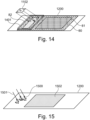
14 eine Darstellung eines Belichtungsvorgangs mit einer Masterplatte in Reflexion, -
15 eine mittels des Belichtungsvorgangs der14 hergestellte Vorrichtung, -
16-21 Darstellungen zur Erläuterung der Herstellung einer Masterplatte, -
22 eine Herstellungsvorrichtung gemäß einem Ausführungsbeispiel, -
23 ein Schichtstapel in der Herstellungsvorrichtung der22 , und -
24 ein Diagramm zur Herstellung der Wirkungsweise eines holografischen Diffusors in verschiedenen Ausführungsbeispielen.
-
1 a schematic representation of a device according to an embodiment, -
2A ,2B ,3A ,3B ,4A ,4B ,5A ,5B ,6A ,6B , different properties of holographic markings of different embodiments, -
7A and7B illustrate shading in some embodiments, -
8 ,9 and10 Master plates according to various embodiments, -
11 a manufacturing device according to an embodiment, -
12 a representation of an exposure process with a master plate in transmission, -
13 one with the exposure of the12 manufactured device, -
14 a representation of an exposure process with a master plate in reflection, -
15 one by means of the exposure process of the14 manufactured device, -
16-21 Illustrations to explain the production of a master plate, -
22 a manufacturing device according to an embodiment, -
23 a layer stack in the manufacturing device of the22 , and -
24 a diagram for the production of the mode of operation of a holographic diffuser in various embodiments.
Im Folgenden werden verschiedene Ausführungsbeispiele detailliert erläutert. Diese sind nicht als einschränkend auszulegen. Variationen und Modifikationen, welche für eines der Ausführungsbeispiele beschrieben werden, sind auch auf andere Ausführungsbeispiele anwendbar und werden nicht wiederholt erläutert.Various embodiments are explained in detail below. These are not to be interpreted as limiting. Variations and modifications described for one of the embodiments are also applicable to other embodiments and will not be explained repeatedly.
Gleiche Bezugszeichen in den Figuren bezeichnen gleiche oder einander entsprechende Elemente, welche ebenfalls nicht näher erläutert werden.The same reference symbols in the figures denote the same or corresponding elements, which are also not explained in more detail.
Die Vorrichtung der
Die holografische Markierung 13 kann als Volumenhologramm in das holografische Material einbelichtet sein. Die holografische Markierung 13 kann winkelsensitiv und/oder wellenlängensensitiv sein, das heißt sie wird nur bei Licht unter einer bestimmten Wellenlänge und/oder einer bestimmten Beleuchtungsrichtung sichtbar, und/oder kann nur unter einem bestimmten Winkel betrachtet werden, da sie Licht nur in eine entsprechende Richtung streut. Derartige Winkel und Wellenlängen werden bei dem Einbelichten der holografischen Markierung 13 in das holografische Material festgelegt, indem zur Belichtung Licht einer entsprechenden Wellenlänge verwendet wird, und die Objekt- und Referenzwellen unter entsprechenden Winkeln eingestrahlt werden. Zu bemerken ist, dass „Licht“ in diesem Sinn nicht auf den sichtbaren Bereich begrenzt ist und beispielsweise auch Markierungen mittels Infrarotlicht oder Ultraviolettlicht belichtet werden können, die dann entsprechend auch nur mit Infrarotlicht oder ultravioletten Licht betrachtbar sind.The
Das Haupthologramm 12 kann hingegen zudem oder alternativ auch für andere Wellenlängen und Winkel ausgestaltet sein.The
Dies wird nunmehr unter Bezugnahmen auf die
In den
Die
Die
Die
Die
In den obigen Beispielen ist in den jeweiligen Unterfiguren „B“ das von dem Haupthologramm 12 erzeugte Lichtmuster stets sichtbar. Bei anderen Ausführungsbeispielen muss auch für das Haupthologramm eine spezielle Beleuchtung verwendet werden, die sich von der Beleuchtung für die Markierungen unterscheidet, damit das entsprechende Lichtmuster sichtbar wird.In the above examples, the light pattern generated by the
Manche Markierungen werden nur während des Herstellungsprozesses der Vorrichtung benötigt, nicht jedoch im späteren Einsatz. Beispielsweise können Justagemarkierungen verwendet werden, um einen Einbauort so zu bestimmen, dass das Haupthologramm 12 an einem korrekten Ort innerhalb einer Vorrichtung ist. Nach dem entsprechenden Einbau werden die Justagemarkierungen dann nicht mehr benötigt. In derartigen Fällen kann der Einbau so erfolgen, dass die Markierungen dann im eingebauten Zustand nicht mehr sichtbar sein können, weil eine korrekte Beleuchtung und/oder Beobachtung aufgrund von Abschattung nicht mehr erfolgen kann. Dies ist in den
Die
Vorrichtungen wie oben erläutert können mittels Masterplatten hergestellt werden. Zur Herstellung von Vorrichtungen wie oben erläutert wird die Masterplatte dann benachbart zu einem holografischen Material (beispielsweise auf einer Trägerfolie angeordneten Photopolymer) angeordnet, und das holografische Material wird mittels der Masterplatte belichtet. Dies wird später noch detailliert erläutert.Devices as described above can be manufactured using master plates. To manufacture devices as described above, the master plate is then placed adjacent to a holographic material (e.g., a photopolymer disposed on a carrier film), and the holographic material is exposed using the master plate. This will be explained in more detail later.
Die
Der holografische Diffusor 82 dient zur Einbelichtung von holografischen Markierungen, wie den holografischen Markierungen 13 (13A-13C) der vorstehenden Figuren. Hierzu wird mit Hilfe eines modulierten Lichtstrahls 83 ein entsprechendes Muster (entsprechend der gewünschten Markierung) in das holografische Material beschrieben. Wie weiter unten erläutert kann der Lichtstrahl 83 beispielsweise durch einen räumlichen Lichtmodulator wie eine Flüssigkristallanzeige (LC-Display) oder eine Mikrospiegelanordnung (DMD, digital micromirror device) moduliert werden, oder ein entsprechendes Muster kann abgerastert werden.The
Dies wird detaillierter in
Die
Die
Wie bereits erwähnt kann der holografische Diffusor 82 als Transmissionsdiffusor oder als Reflexionsdiffusor ausgestaltet sein, und dementsprechend kann das Masterhologramm 81 als Reflexionshologramm oder Transmissionshologramm ausgestaltet sein. Je nach Ausgestaltung unterscheidet sich dann die Anordnung bei der Belichtung des holografischen Materials. Dies wird nun unter Bezugnahme auf die
Die
Die
Die
In den obenstehenden Figuren ist der holografische Diffusor 82 nur auf einer Seite des Masterhologramms 81 gezeigt. Es können jedoch auch mehrere Bereiche von holografischen Diffusoren bereitgestellt sein, beispielsweise um holografische Markierungen auf verschiedenen Seiten des Haupthologramms bereitzustellen.In the above figures, the
Ein möglicher Herstellungsprozess für die Masterplatte wird nunmehr unter Bezugnahme auf die
Zunächst werden, wie in
In einem nächsten Schritt, der in
Die
Im nächsten Schritt wird dann eine dickere Glasplatte 2000, beispielsweise mit einer Dicke zwischen 3mm und 10mm, zusammen mit einem optischen Kleber (z.B. OCA, optically clear adhesive) oder einem flüssigen Optikkleber(kit) auf der der Glasplatte 1800 gegenüberliegenden Seite auf die Vorrichtung aufgebracht, wie dies in
Die
Während des Belichtungsvorgangs enthält ein entsprechender Schichtstapel wie er in
Das Belichtungsmodul 2022 kann dabei ähnlich wie in der
Bei der obigen Einrichtung wird der Diffusor der Masterplatte in Transmission beleuchtet. Die Funktion des Diffusors ist in
ZITATE ENTHALTEN IN DER BESCHREIBUNGQUOTES CONTAINED IN THE DESCRIPTION
Diese Liste der vom Anmelder aufgeführten Dokumente wurde automatisiert erzeugt und ist ausschließlich zur besseren Information des Lesers aufgenommen. Die Liste ist nicht Bestandteil der deutschen Patent- bzw. Gebrauchsmusteranmeldung. Das DPMA übernimmt keinerlei Haftung für etwaige Fehler oder Auslassungen.This list of documents submitted by the applicant was generated automatically and is included solely for the convenience of the reader. This list is not part of the German patent or utility model application. The DPMA assumes no liability for any errors or omissions.
Zitierte PatentliteraturCited patent literature
- DE 10 2007 061 626 A1 [0006]DE 10 2007 061 626 A1 [0006]
- DE 4 124 203 A1 [0006]DE 4 124 203 A1 [0006]
- DE 10 2014 117 511 A1 [0006]DE 10 2014 117 511 A1 [0006]
- DE 10 2017 211 914 A1 [0006]DE 10 2017 211 914 A1 [0006]
- EP 3 955 051 A1 [0006]EP 3 955 051 A1 [0006]
- US 2020 / 0 301 157 A1 [0006]US 2020 / 0 301 157 A1 [0006]
- DE-OS 1 963 787 [0006]DE-OS 1 963 787 [0006]
Claims (19)
Priority Applications (2)
| Application Number | Priority Date | Filing Date | Title |
|---|---|---|---|
| DE102023135327.6A DE102023135327A1 (en) | 2023-12-15 | 2023-12-15 | Device with holographic marking, master plate for producing such a device, and corresponding methods |
| PCT/EP2024/086265 WO2025125592A1 (en) | 2023-12-15 | 2024-12-13 | Device comprising holographic marking, master plate for producing such a device, and corresponding methods |
Applications Claiming Priority (1)
| Application Number | Priority Date | Filing Date | Title |
|---|---|---|---|
| DE102023135327.6A DE102023135327A1 (en) | 2023-12-15 | 2023-12-15 | Device with holographic marking, master plate for producing such a device, and corresponding methods |
Publications (1)
| Publication Number | Publication Date |
|---|---|
| DE102023135327A1 true DE102023135327A1 (en) | 2025-06-18 |
Family
ID=94210424
Family Applications (1)
| Application Number | Title | Priority Date | Filing Date |
|---|---|---|---|
| DE102023135327.6A Pending DE102023135327A1 (en) | 2023-12-15 | 2023-12-15 | Device with holographic marking, master plate for producing such a device, and corresponding methods |
Country Status (2)
| Country | Link |
|---|---|
| DE (1) | DE102023135327A1 (en) |
| WO (1) | WO2025125592A1 (en) |
Citations (3)
| Publication number | Priority date | Publication date | Assignee | Title |
|---|---|---|---|---|
| DE102007052951A1 (en) * | 2007-10-31 | 2009-05-07 | Bundesdruckerei Gmbh | Method and device for producing holograms as security elements |
| DE102013217291A1 (en) * | 2013-08-29 | 2015-03-05 | Bundesdruckerei Gmbh | Method for decentralizing a security document |
| DE102020127879A1 (en) * | 2020-10-22 | 2022-04-28 | Bundesdruckerei Gmbh | PROCEDURE FOR VERIFICATION OF THE AUTHENTICITY OF A SECURITY FEATURE OF A VALUABLE OR SECURITY PRODUCT MADE FROM SEVERAL PARTS |
Family Cites Families (9)
| Publication number | Priority date | Publication date | Assignee | Title |
|---|---|---|---|---|
| DE4124203A1 (en) | 1991-07-20 | 1993-01-21 | Krupp Ag | HOLOGRAPHIC TAGS |
| JPH0872585A (en) * | 1994-09-09 | 1996-03-19 | Nippondenso Co Ltd | Hologram for head-up display device |
| US5776286A (en) * | 1997-01-29 | 1998-07-07 | Motorola, Inc. | Hologram manufacturing process and method for efficiently providing a multi-holographic optical element substrate unit |
| DE102007061626B4 (en) | 2007-12-18 | 2019-06-06 | Tesa Scribos Gmbh | Method for labeling labels depending on different labeling |
| DE102012216219B4 (en) * | 2012-09-12 | 2021-11-11 | Bundesdruckerei Gmbh | Method for producing a volume hologram |
| DE102014117511A1 (en) | 2014-11-28 | 2016-06-02 | Friedrich-Schiller-Universität Jena | Method and apparatus for interferometric testing |
| DE102017211914A1 (en) | 2017-07-12 | 2019-01-17 | Robert Bosch Gmbh | Method for calibrating a projection device for a data goggle and projection device for a data goggle for carrying out a method. |
| JP7346864B2 (en) | 2019-03-22 | 2023-09-20 | セイコーエプソン株式会社 | Display device control method |
| EP3955051A1 (en) | 2020-08-10 | 2022-02-16 | Carl Zeiss Vision International GmbH | Spectacle lens and a method for producing a spectacle lens |
-
2023
- 2023-12-15 DE DE102023135327.6A patent/DE102023135327A1/en active Pending
-
2024
- 2024-12-13 WO PCT/EP2024/086265 patent/WO2025125592A1/en active Pending
Patent Citations (3)
| Publication number | Priority date | Publication date | Assignee | Title |
|---|---|---|---|---|
| DE102007052951A1 (en) * | 2007-10-31 | 2009-05-07 | Bundesdruckerei Gmbh | Method and device for producing holograms as security elements |
| DE102013217291A1 (en) * | 2013-08-29 | 2015-03-05 | Bundesdruckerei Gmbh | Method for decentralizing a security document |
| DE102020127879A1 (en) * | 2020-10-22 | 2022-04-28 | Bundesdruckerei Gmbh | PROCEDURE FOR VERIFICATION OF THE AUTHENTICITY OF A SECURITY FEATURE OF A VALUABLE OR SECURITY PRODUCT MADE FROM SEVERAL PARTS |
Also Published As
| Publication number | Publication date |
|---|---|
| WO2025125592A1 (en) | 2025-06-19 |
Similar Documents
| Publication | Publication Date | Title |
|---|---|---|
| EP0537439B1 (en) | Security element | |
| EP2303594B1 (en) | Security element | |
| EP3065002B1 (en) | Safety element and method for manufacturing a safety element | |
| EP2738624B1 (en) | Hologram and security document with colour patterns of different spectral colours | |
| EP1697146B1 (en) | Data support with identifications written thereon by means of a laser beam and method for production thereof | |
| WO2014026918A1 (en) | Light guide plate comprising decoupling elements | |
| EP3458902A2 (en) | Method for producing security elements having a lenticular flip | |
| DE102013200980B4 (en) | Process for subsequent holographic labeling and device for subsequent holographic labeling | |
| EP3112948A1 (en) | Method and device for verifying holograms with watermark-like structure | |
| WO2020216541A1 (en) | Method and device for producing a hologram, hologram and illumination device for a vehicle | |
| EP1309941A2 (en) | Optically active structure for personalizing cards and the like, and method for the production thereof | |
| EP3657266A1 (en) | Method and device for creating a hologram | |
| WO2001029764A1 (en) | Data carrier comprising authentication tags and a production method therefor | |
| EP2895921B1 (en) | Method for producing a volume reflection hologram having improved marker formation | |
| DE102023135327A1 (en) | Device with holographic marking, master plate for producing such a device, and corresponding methods | |
| WO2024033354A1 (en) | Method for replicating a plurality of holograms by means of a typecase principle | |
| DE112006002534T5 (en) | Optical encoder scale unit with attached optical reference marks | |
| DE102022119989A1 (en) | DEVICE FOR THE REPLICATION OF A PLURALITY OF HOLOGRAMS USING A BOX PRINCIPLE | |
| WO2025068496A1 (en) | "sequential exposure of hologram stacks" |
Legal Events
| Date | Code | Title | Description |
|---|---|---|---|
| R163 | Identified publications notified |