DE102023130834A1 - Power generation facility - Google Patents
Power generation facility Download PDFInfo
- Publication number
- DE102023130834A1 DE102023130834A1 DE102023130834.3A DE102023130834A DE102023130834A1 DE 102023130834 A1 DE102023130834 A1 DE 102023130834A1 DE 102023130834 A DE102023130834 A DE 102023130834A DE 102023130834 A1 DE102023130834 A1 DE 102023130834A1
- Authority
- DE
- Germany
- Prior art keywords
- push rod
- crank
- power generation
- permanent magnet
- coil
- Prior art date
- Legal status (The legal status is an assumption and is not a legal conclusion. Google has not performed a legal analysis and makes no representation as to the accuracy of the status listed.)
- Pending
Links
Images


Classifications
-
- H—ELECTRICITY
- H02—GENERATION; CONVERSION OR DISTRIBUTION OF ELECTRIC POWER
- H02K—DYNAMO-ELECTRIC MACHINES
- H02K7/00—Arrangements for handling mechanical energy structurally associated with dynamo-electric machines, e.g. structural association with mechanical driving motors or auxiliary dynamo-electric machines
- H02K7/06—Means for converting reciprocating motion into rotary motion or vice versa
- H02K7/075—Means for converting reciprocating motion into rotary motion or vice versa using crankshafts or eccentrics
-
- H—ELECTRICITY
- H02—GENERATION; CONVERSION OR DISTRIBUTION OF ELECTRIC POWER
- H02K—DYNAMO-ELECTRIC MACHINES
- H02K41/00—Propulsion systems in which a rigid body is moved along a path due to dynamo-electric interaction between the body and a magnetic field travelling along the path
- H02K41/02—Linear motors; Sectional motors
- H02K41/03—Synchronous motors; Motors moving step by step; Reluctance motors
- H02K41/031—Synchronous motors; Motors moving step by step; Reluctance motors of the permanent magnet type
-
- H—ELECTRICITY
- H02—GENERATION; CONVERSION OR DISTRIBUTION OF ELECTRIC POWER
- H02K—DYNAMO-ELECTRIC MACHINES
- H02K7/00—Arrangements for handling mechanical energy structurally associated with dynamo-electric machines, e.g. structural association with mechanical driving motors or auxiliary dynamo-electric machines
- H02K7/18—Structural association of electric generators with mechanical driving motors, e.g. with turbines
- H02K7/1869—Linear generators; sectional generators
- H02K7/1876—Linear generators; sectional generators with reciprocating, linearly oscillating or vibrating parts
Landscapes
- Engineering & Computer Science (AREA)
- Power Engineering (AREA)
- Physics & Mathematics (AREA)
- Chemical & Material Sciences (AREA)
- Combustion & Propulsion (AREA)
- Electromagnetism (AREA)
- Connection Of Motors, Electrical Generators, Mechanical Devices, And The Like (AREA)
- Permanent Magnet Type Synchronous Machine (AREA)
Abstract
Die Erfindung bezieht sich auf eine Stromerzeugungseinrichtung mit wenigstens einer zylindrischen Spulenwicklung 1, die einen Innenraum 2 umschließt, in dem wenigstens ein ringförmiger Permanentmagnet 4 angeordnet ist, wobei die Spulenwicklung 1 und der Permanentmagnet 4 relativ koaxial zueinander bewegbar antreibbar angeordnet sind. Eine von einem Antrieb drehbar antreibbare Kurbelwelle 14 weist eine Kurbel 13 auf, die sich radial von der Kurbelwelle 14 wegerstreckt, wobei von der Kurbel 13 der Permanentmagnet 4 koaxial zur feststehenden Spulenwicklung 1 bewegbar antreibbar ist.
Description
Die Erfindung bezieht sich auf eine Stromerzeugungseinrichtung mit wenigstens einer zylindrischen Spulenwicklung, die einen Innenraum umschließt, in dem wenigstens ein ringförmiger Permanentmagnet angeordnet ist, wobei die Spulenwicklung und der Permanentmagnet relativ koaxial zueinander bewegbar antreibbar angeordnet sind.The invention relates to a power generation device with at least one cylindrical coil winding which encloses an interior in which at least one annular permanent magnet is arranged, wherein the coil winding and the permanent magnet are arranged so as to be movable relative to one another coaxially.
Aufgabe der Erfindung ist es daher eine Stromerzeugungseinrichtung der eingangs genannten Art zu schaffen, die einen einfachen und kostengünstigen Aufbau geringen Bauvolumens sowie einen hohen Wirkungsgrad aufweist.The object of the invention is therefore to provide a power generation device of the type mentioned above which has a simple and cost-effective design with a small construction volume and a high degree of efficiency.
Diese Aufgabe wird erfindungsgemäß dadurch gelöst, daß eine von einem Antrieb drehbar antreibbare Kurbelwelle eine Kurbel aufweist, die sich radial von der Kurbelwelle wegerstreckt, wobei von der Kurbel der Permanentmagnet koaxial zur feststehenden Spulenwicklung bewegbar antreibbar ist.This object is achieved according to the invention in that a crankshaft which can be driven rotatably by a drive has a crank which extends radially away from the crankshaft, wherein the permanent magnet can be driven by the crank in a movable manner coaxially to the fixed coil winding.
Durch die Kurbelwelle und Kurbel ergibt sich ein nur geringes Bauvolumen erfordernder Aufbau, der verschleißarm ist und somit eine hohe Lebensdauer aufweist und einen hohen Wirkungsgrad besitz. Dabei ist der Aufbau sehr kostengünstig herstellbar.The crankshaft and crank result in a compact design that is low-wear, long-lasting, and highly efficient. The design is also very cost-effective to manufacture.
Durch die erfindungsgemäße Stromerzeugungseinrichtung wird sauberer, zu 100% CO2-Schadstoffreier Strom erzeugt.The power generation device according to the invention produces clean, 100% CO2-free electricity.
Weiterhin wird die Aufgabe erfindungsgemäß dadurch gelöst, daß die von einem Antrieb drehbar antreibbare Kurbelwelle zumindest eine erste Kurbel und eine zweite Kurbel aufweist, wobei die erste Kurbel und die zweite Kurbel um einen Winkel zueinander versetzt sich radial von der Kurbelwelle wegerstrecken und wobei von der ersten Kurbel die Spulenwicklung und von der zweiten Kurbel der Permanentmagnet koaxial bewegbar antreibbar ist.Furthermore, the object is achieved according to the invention in that the crankshaft which can be driven rotatably by a drive has at least a first crank and a second crank, wherein the first crank and the second crank extend radially away from the crankshaft at an angle to one another, and wherein the coil winding can be driven coaxially by the first crank and the permanent magnet by the second crank.
Neben den Vorteilen zu Anspruch 1 erhält man durch die gegenläufige Bewegung von Spulenwicklung und Permanentmagnet mit einem doppelten Wirkungshub eine verdoppelte Relativgeschwindigkeit von Spulenwicklung und Permanentmagnet und somit eine doppelte Induktivität und doppelte Voltzahl.In addition to the advantages of
Die gegenläufige Bewegung erzielt einen doppelten Wirk-Gesamthub, wobei jede einzelne Spulenwicklung synchron in Folge gleich mehrfach von den einzelnen Permanentmagneten tangiert wird, wodurch enorme Massen an Wechselspannungsimpulsen erzielt werden.The counter-rotating movement achieves a double total effective stroke, whereby each individual coil winding is synchronously touched several times in succession by the individual permanent magnets, thereby achieving enormous masses of alternating voltage pulses.
Gleichzeitig erhält man eine Lastenverteilung der Beschleunigungsenergien auf die gesamte Mechanik, da die Nenndrehzahl des Antriebs dabei sehr klein gehalten werden kann.At the same time, the acceleration energy is distributed evenly across the entire mechanism, as the nominal speed of the drive can be kept very low.
Ein besonders hoher Wirkungsgrad wird erreicht, wenn die erste Kurbel und die zweite Kurbel sich diametral zueinander von der Kurbelwelle wegerstrecken.A particularly high efficiency is achieved when the first crank and the second crank extend diametrically opposite each other from the crankshaft.
Zur koaxialen Bewegung können die Spulenwicklung oder die Spulenwicklungen und/oder der Permanentmagnet oder die Permanentmagnete in Führungen koaxial geführt sein.For coaxial movement, the coil winding or coil windings and/or the permanent magnet or permanent magnets can be guided coaxially in guides.
Ist die Spulenwicklung oder die Spulenwicklungen an einem Spulenträger angeordnet, so werden diese auf einfache Art positionsstabil gehalten.If the coil winding or coil windings are arranged on a coil carrier, they are held in a stable position in a simple manner.
Eine einfache Kühlung der Spulenwicklung oder die Spulenwicklungen erfolgt dadurch, daß die Spulenwicklung oder die Spulenwicklungen teilweise radial nach außen freiliegend in dem Spulenträger angeordnet sind. A simple cooling of the coil winding or the coil windings is achieved by arranging the coil winding or the coil windings in the coil carrier in such a way that they are partially exposed radially outwards.
Durch die gegenläufige Bewegung von Spulenwicklung oder Spulenwicklungen und Permanentmagneten kommt es zu einem permanenten Luftansaugen und Luftverdrängen im Innenraum der Spulenwicklung oder Spulenwicklungen und dadurch zur Kühlung der Spulenwicklung oder Spulenwicklungen und Permanentmagnete. Leistungsverluste durch Erwärmung werden dadurch wesentlich verringert. Die erzeugte Voltzahl kann dadurch weitgehend konstant gehalten werden.The counter-rotating motion of the coil winding(s) and the permanent magnets results in a constant air intake and expulsion within the coil winding(s), thereby cooling the coil winding(s) and the permanent magnets. This significantly reduces power losses due to overheating. The generated voltage can thus be kept largely constant.
Eine Bauraum sparende und kostengünstige Ausbildung besteht darin, daß der Spulenträger parallel in einem Abstand zueinander zwei Spulenwicklungen oder zwei Reihen von Spulenwicklungen trägt und von einer Schubstange koaxial bewegbar antreibbar ist.A space-saving and cost-effective design consists in the coil carrier carrying two coil windings or two rows of coil windings in parallel at a distance from each other and being driven coaxially by a push rod.
Zur stabil geführten Bewegung kann der Spulenträger an einem feststehenden Rolltisch koaxial geführt sein.For stable movement, the coil carrier can be guided coaxially on a fixed roller table.
Die erste Kurbel kann über eine erste Schubstange mit dem Spulenträger verbunden sein.The first crank can be connected to the spool carrier via a first push rod.
Ist dabei die erste Schubstange koaxial mindestens zweiteilig ausgebildet und sind jeweils zwei Teile der ersten Schubstange über eine Druckfeder miteinander verbunden, so wird der tatsächliche Wirkhub durch das Stauchen und Ausdehnen der Druckfeder erweitert. Des Weiteren erhöht die Druckfeder durch ihre Arbeit die Geschwindigkeit beim Ein- und Austauchen des Permanentmagneten in die Spulenwicklung, wodurch die erzeugte Voltzahl erhöht wird.If the first push rod is coaxially constructed in at least two parts and each of the two parts of the first push rod is connected to each other via a compression spring, the effective stroke is extended by the compression and expansion of the compression spring. Furthermore, the compression spring's action increases the speed at which the permanent magnet enters and exits the coil winding, thereby increasing the generated voltage.
Zum Bewegungsantrieb des Permanentmagneten oder der Permanentmagnete kann die Kurbel oder zweite Kurbel über eine Schubstange oder zweite Schubstange mit dem Permanentmagnet oder den Permanentmagneten verbunden sein, wobei der Permanentmagnet oder die Permanentmagnete auf der Schubstange oder zweiten Schubstange angeordnet sein können.To drive the movement of the permanent magnet or the permanent magnets, the crank or second crank can be connected to the permanent magnet or the permanent magnets via a push rod or second push rod, wherein the permanent magnet or the permanent magnets can be arranged on the push rod or second push rod.
Ist dabei die Schubstange oder zweite Schubstange koaxial mindestens zweiteilig ausgebildet und sind jeweils zwei Teile der Schubstange oder zweiten Schubstange über eine Druckfeder miteinander verbunden, so wird der tatsächliche Wirkhub durch das Stauchen und Ausdehnen der Druckfeder erweitert.If the push rod or second push rod is coaxially formed in at least two parts and two parts of the push rod or second push rod are connected to each other via a compression spring, the actual effective stroke is extended by compressing and expanding the compression spring.
Zur koaxialen Führung kann die Schubstange oder zweite Schubstange an ihren ersten und zweiten Endbereichen in ersten und zweiten Führungsöffnungen von feststehenden ersten und zweiten Führungsstücken koaxial geführt sein, wobei der die Druckfeder aufweisende Bereich der Schubstange oder zweiten Schubstange in der ersten Führungsöffnung des ersten Führungsstücks geführt sein kann.For coaxial guidance, the push rod or second push rod can be guided coaxially at its first and second end regions in first and second guide openings of fixed first and second guide pieces, wherein the region of the push rod or second push rod having the compression spring can be guided in the first guide opening of the first guide piece.
Durch die Führung in den Führungsstücken ist es möglich, daß die Schubstange oder zweite Schubstange von Permanentmagnet oder von den Permanentmagneten auf schwebende Art mit kleinstmöglichem Luftspalt der Permanentmagnete zur Spulenwicklung geführt ist. Dabei können die Führungen Lager wie z.B. Axial-Teflon-Nadellager aufweisen, die nur sehr geringe Reibung aufweisen.The guides in the guide pieces allow the push rod or second push rod to be guided from the permanent magnet(s) to the coil winding in a floating manner, with the smallest possible air gap between the permanent magnets. The guides can be equipped with bearings such as axial Teflon needle bearings, which offer very low friction.
Zur einfachen Verbindung von Kurbel und Schubstange unter Vermeidung eines Verklemmens der Schubstange im kann das freie Ende der ersten Kurbel um eine zur Kurbelwelle parallele Schwenkachse an der ersten Schubstange angelenkt und/oder das freie Ende der Kurbel oder zweiten Kurbel um eine zur Kurbelwelle parallele Schwenkachse oder zweite Schwenkachse an der zweiten Schubstange schwenkbar angelenkt sein.To easily connect the crank and push rod while avoiding jamming of the push rod, the free end of the first crank can be pivoted on the first push rod about a pivot axis parallel to the crankshaft and/or the free end of the crank or second crank can be pivoted on the second push rod about a pivot axis parallel to the crankshaft or second pivot axis.
Damit die Permanentmagnete sich nicht voneinander wegbewegen, können die Anzahl der Permanentmagnete axial zu einem Permanentmagnetpaket verspannt sein.To prevent the permanent magnets from moving away from each other, the number of permanent magnets can be axially clamped to form a permanent magnet package.
Dies ist auf einfache Weise dadurch möglich, daß die Anzahl der Permanentmagnete mittels einer Schraubverbindung axial zu einem Permanentmagnetpaket verspannt sind.This is easily achieved by axially clamping the number of permanent magnets into a permanent magnet package using a screw connection.
Die Spulenwicklungen sind vorzugsweise in vorbestimmten axialen Abständen voneinander angeordnet und die Permanentmagnete sind vorzugsweise in vorbestimmten axialen Abständen zueinander angeordnet.The coil windings are preferably arranged at predetermined axial distances from one another and the permanent magnets are preferably arranged at predetermined axial distances from one another.
Damit leistungssteigend immer eine Überdeckung von Spulenwicklungen und Permanentmagneten vorhanden ist können die axialen Abstände der Spulenwicklungen den Abständen der Permanentmagnete und die Breite der Spulenwicklungen der Breite der Permanentmagnete entsprechen, wobei die Breite der Spulenwicklungen und Permanentmagnete größer ist als die Abstände zwischen Spulenwicklungen und Permanentmagneten.In order to ensure that there is always an overlap between coil windings and permanent magnets, increasing performance, the axial distances of the coil windings can correspond to the distances between the permanent magnets and the width of the coil windings can correspond to the width of the permanent magnets, whereby the width of the coil windings and permanent magnets is greater than the distances between the coil windings and permanent magnets.
Zur Sicherstellung der Abstände zwischen den Spulenwicklungen und/oder den Permanentmagneten können in einfacher Weise die Abstände durch unmagnetische Distanzringe zwischen den Spulenwicklungen und/oder Permanentmagneten vorbestimmt sein.To ensure the distances between the coil windings and/or the permanent magnets, the distances can be predetermined in a simple manner by non-magnetic spacer rings between the coil windings and/or permanent magnets.
Ein Ausführungsbeispiel der Erfindung ist in der Zeichnung dargestellt und wird im Folgenden näher beschrieben. Es zeigen
-
1 einen Längsschnitt entlang der Linie B-B in2 einer Einheit aus Spulenwicklungspaket und Permanentmagnetpaket einer Stromerzeugungseinrichtung -
2 eine Draufsicht auf mehrere Einheiten aus Permanentmagnetpaketeinheiten und Spulenwicklungspaketeinheiten einer Stromerzeugungseinrichtung nach1 -
3 einen Querschnitt der Stromerzeugungseinrichtung entlang der Linie A-A in2 -
4 eine Stirnansicht eines Spulenträgers der Stromerzeugungseinrichtung nach1 -
5 eine Seitenansicht des Spulenträgers nach4 .
-
1 a longitudinal section along the line BB in2 a unit consisting of a coil winding package and a permanent magnet package of a power generation device -
2 a plan view of several units of permanent magnet package units and coil winding package units of a power generation device according to1 -
3 a cross-section of the power generating facility along the line AA in2 -
4 a front view of a coil carrier of the power generating device according to1 -
5 a side view of the coil carrier after4 .
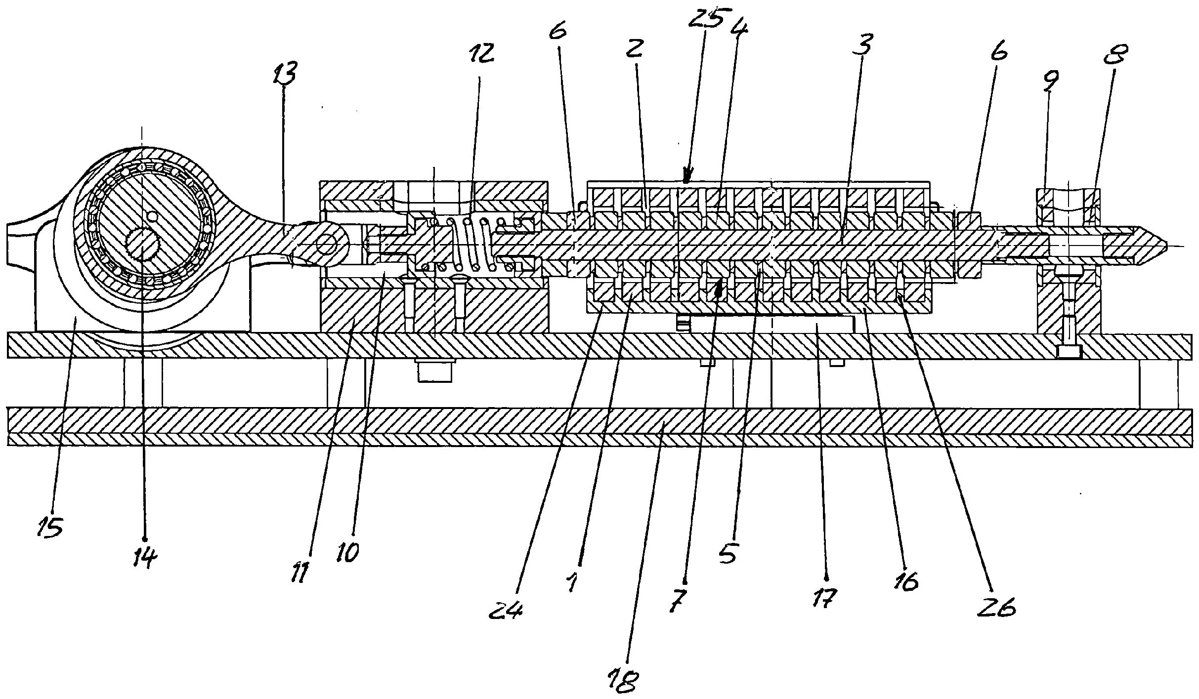
Die in den Figuren dargestellte Stromerzeugungseinrichtung weist mehrere Spulenwicklungen 1 auf, die jeweils einen zylindrischen Innenraum 2 umschließen, in dem koaxial zur Spulenwicklung 1 mehrere ringförmige Permanentmagnete 4 nebeneinander auf einer zweiten Schubstange 3 angeordnet sind. Durch zwischen den einzelnen Permanentmagneten 4 angeordnete unmagnetische zweite Distanzringe 5 werden die Permanentmagnete 4 auf vorbestimmte axiale Abstände voneinander gehalten.The power generation device illustrated in the figures comprises a plurality of
Die Spulenwicklungen 1 sind abwechselnd rechts und links gewickelt. Die Permanentmagnete 4 sind jeweils gleichpolig zueinander angeordnet. An den Endbereichen des Permanentmagnetpakets 7 weist die zweite Schubstange 3 Gewinde auf, auf die Muttern 6 aufgeschraubt sind, die die Permanentmagnete 4 zu dem Permanentmagnetpaket 7 axial verspannen.The
In
Außerhalb des Permanentmagnetpakets 7 ist das linke Ende der zweiten Schubstange 3 zweiteilig ausgebildet und durch eine dritte Führungsöffnung 10 eines feststehenden ersten Führungsstücks 11 verschiebbar geführt.Outside the permanent magnet package 7, the left end of the
Zwischen den einander zugewandten Enden der beiden Teile der zweiten Schubstange 3 ist eine zweite Schraubendruckfeder 12 angeordnet, die die beiden Teile der zweiten Schubstange 3 miteinander verbindet.A second
Der nicht die Permanentmagnete tragende Teil der zweiten Schubstange 3 ist an seinem die Permanentmagnete tragenden Teil abgewandten Ende an eine zweite Kurbel 13 angelenkt. Die zweite Kurbel 13 ist exzentrisch radial an einer Kurbelwelle 14 gelagert, die sich quer zur Längserstreckung der zweiten Schubstange 3 erstreckt und von einem nicht dargestellten Antrieb drehbar antreibbar ist.The part of the
Die Kurbelwelle 14 ist an feststehenden Lagerböcken 15 drehbar gelagert.The
Wie insbesondere in
Zwischen diesen beiden Anordnungen von zweiter Schubstange 3 und Permanentmagnetpaket 7 ist parallel zu diesen eine Anordnung mit der Spulenwicklung 1 anordnet, wie sie in den
Dabei sind in einem Spulenträger 16 parallel zueinander zwei Spulenwicklungspakete 25 von Spulenwicklungen 1 angeordnet, die sich jeweils koaxial zu den Permanentmagnetpaketen 7 erstrecken. In den zylindrischen Innenräumen 2 der Spulenwicklungspakete 25 befinden sich jeweils die Permanentmagnetpakete 7 mit nur geringem radialem Luftspalt zu den Spulenwicklungen 1 der Spulenwicklungspakete 25.
Der Spulenträger 16 ist mittels eines Rolltischs 17 auf einer Bodenplatte 18 der Stromerzeugungseinrichtung quer zur Kurbelwelle 14 verschiebbar geführt.In a
The
An seinem in
Die erste Schubstange 19 ist durch eine erste Führungsöffnung des feststehenden ersten Führungsstücks 11 verschiebbar geführt.The
Zwischen den einander zugewandten Enden der beiden Teile der ersten Schubstange 19 ist eine erste Schraubendruckfeder 21 angeordnet, die die beiden Teile der ersten Schubstange 19 miteinander verbindet.A first
Der dem Spulenträger 16 abgewandte Teil der ersten Schubstange 19 ist an seinem dem Spulenträger 16 abgewandten Ende an einer ersten Kurbel 22 um eine zur Kurbelwelle 14 parallele Schwenkachse angelenkt. Die erste Kurbel 22 ist exzentrisch radial an der Kurbelwelle 14 gelagert.The part of the
Der aus einem unmagnetischen Werkstoff bestehende Spulenträger 16 ist an seiner dem Rolltisch 17 abgewandten oberen Hälfte offen. In der unteren Hälfte 23 sind entsprechen der Spulenwicklungen 1 Aufnahmenuten 24 zur Aufnahme der Spulenwicklungen 1 ausgebildet, in die die Spulenwicklungen 1 eingesetzt sind. Zwischen die einzelnen Spulenwicklungen 1 ragen einteilig mit dem Spulenträger 16 ausgebildete Stege 26, die die Spulenwicklungen 1 als Distanzringe auf einem Abstand voneinander halten, der der Breite der zweiten Distanzringe 5 des Permanentmagnetpakets 7 entspricht.The
Die Anzahl der Spulenwicklungen 1 der Spulenwicklungspakete 25 ist geradzahlig, während die Anzahl der Permanentmagnete 4 der Permanentmagnetpakete 7 ungeradzahlig ist.The number of
Die erste Kurbel 22 und die zweite Kurbel 13 erstrecken sich einander entgegengesetzt von der Kurbelwelle 14 weg, so daß die Spulenwicklungspakete 25 und die Permanentmagnetpakete 7 immer eine gegenläufige Bewegung zueinander vollführen.The
Wie in
BezugszeichenlisteList of reference symbols
- 11
- SpulenwicklungenCoil windings
- 22
- InnenraumInterior
- 33
- zweite Schubstangesecond push rod
- 44
- PermanentmagnetePermanent magnets
- 55
- zweite Distanzringesecond spacer rings
- 66
- Mutternnuts
- 77
- PermanentmagnetpaketPermanent magnet package
- 88
- zweite Führungsöffnungsecond guide opening
- 99
- zweites Führungsstücksecond guide piece
- 1010
- dritte Führungsöffnungthird guide opening
- 1111
- erstes Führungsstückfirst guide piece
- 1212
- zweite Schraubendruckfedersecond helical compression spring
- 1313
- zweite Kurbelsecond crank
- 1414
- Kurbelwellecrankshaft
- 1515
- LagerböckeBearing blocks
- 1616
- Spulenträgercoil carrier
- 1717
- Rolltischrolling table
- 1818
- Bodenplattebase plate
- 1919
- erste Schubstangefirst push rod
- 2121
- erste Schraubendruckfederfirst helical compression spring
- 2222
- erste Kurbelfirst crank
- 2323
- untere Hälftelower half
- 2424
- AufnahmenutenMounting grooves
- 2525
- SpulenwicklungspaketCoil winding package
- 2626
- StegeFootbridges
Claims (16)
Priority Applications (3)
| Application Number | Priority Date | Filing Date | Title |
|---|---|---|---|
| DE102023130834.3A DE102023130834A1 (en) | 2023-11-07 | 2023-11-07 | Power generation facility |
| CN202480013944.4A CN120731553A (en) | 2023-11-07 | 2024-10-28 | Power generation device |
| PCT/EP2024/000057 WO2025098635A1 (en) | 2023-11-07 | 2024-10-28 | Power generating device |
Applications Claiming Priority (1)
| Application Number | Priority Date | Filing Date | Title |
|---|---|---|---|
| DE102023130834.3A DE102023130834A1 (en) | 2023-11-07 | 2023-11-07 | Power generation facility |
Publications (1)
| Publication Number | Publication Date |
|---|---|
| DE102023130834A1 true DE102023130834A1 (en) | 2025-05-08 |
Family
ID=94382073
Family Applications (1)
| Application Number | Title | Priority Date | Filing Date |
|---|---|---|---|
| DE102023130834.3A Pending DE102023130834A1 (en) | 2023-11-07 | 2023-11-07 | Power generation facility |
Country Status (3)
| Country | Link |
|---|---|
| CN (1) | CN120731553A (en) |
| DE (1) | DE102023130834A1 (en) |
| WO (1) | WO2025098635A1 (en) |
Citations (6)
| Publication number | Priority date | Publication date | Assignee | Title |
|---|---|---|---|---|
| US20060208839A1 (en) * | 2005-03-15 | 2006-09-21 | Taylor George W | Wave energy converters (WECs) with linear electric generators (LEGs) |
| CN1996723A (en) * | 2006-05-23 | 2007-07-11 | 邱兆云 | Driving system of the combined line incremental motor and clutch for driving the rotating axis |
| CN201616752U (en) * | 2009-11-23 | 2010-10-27 | 盛润泉 | Generator with magnetic piston |
| KR20100121194A (en) * | 2009-05-08 | 2010-11-17 | 빅터 스미스 에드워드 | The aerogenerator |
| KR101145084B1 (en) * | 2010-06-03 | 2012-05-11 | 이형우 | Wave power generator |
| US20140306532A1 (en) * | 2013-04-16 | 2014-10-16 | Richard Lloyd Gray | Linear Alternator |
Family Cites Families (2)
| Publication number | Priority date | Publication date | Assignee | Title |
|---|---|---|---|---|
| JPH02214461A (en) * | 1989-02-15 | 1990-08-27 | Mitsuba Electric Mfg Co Ltd | Electromagnetic driving device |
| US20140152125A1 (en) * | 2012-04-17 | 2014-06-05 | Richard Lloyd Gray | Linear Alternator |
-
2023
- 2023-11-07 DE DE102023130834.3A patent/DE102023130834A1/en active Pending
-
2024
- 2024-10-28 CN CN202480013944.4A patent/CN120731553A/en active Pending
- 2024-10-28 WO PCT/EP2024/000057 patent/WO2025098635A1/en active Pending
Patent Citations (6)
| Publication number | Priority date | Publication date | Assignee | Title |
|---|---|---|---|---|
| US20060208839A1 (en) * | 2005-03-15 | 2006-09-21 | Taylor George W | Wave energy converters (WECs) with linear electric generators (LEGs) |
| CN1996723A (en) * | 2006-05-23 | 2007-07-11 | 邱兆云 | Driving system of the combined line incremental motor and clutch for driving the rotating axis |
| KR20100121194A (en) * | 2009-05-08 | 2010-11-17 | 빅터 스미스 에드워드 | The aerogenerator |
| CN201616752U (en) * | 2009-11-23 | 2010-10-27 | 盛润泉 | Generator with magnetic piston |
| KR101145084B1 (en) * | 2010-06-03 | 2012-05-11 | 이형우 | Wave power generator |
| US20140306532A1 (en) * | 2013-04-16 | 2014-10-16 | Richard Lloyd Gray | Linear Alternator |
Also Published As
| Publication number | Publication date |
|---|---|
| WO2025098635A1 (en) | 2025-05-15 |
| CN120731553A (en) | 2025-09-30 |
Similar Documents
| Publication | Publication Date | Title |
|---|---|---|
| DE4109566C2 (en) | Vario finder for a photographic camera | |
| DE2247509A1 (en) | ELECTROMAGNETIC POWERED LINEAR MOTOR | |
| DE2649119C2 (en) | Device for inserting coils and slot wedges | |
| DD298017A5 (en) | DEVICE FOR CONVERSION OF LINEAR MOVEMENTS IN TURNING MOVEMENTS | |
| EP0005444B1 (en) | Winding head | |
| EP2432722B1 (en) | Traversing device | |
| DE4243981A1 (en) | ||
| DE102023130834A1 (en) | Power generation facility | |
| EP1619281B1 (en) | Shogging bar drive of a warp knitting machine | |
| DE102023130832A1 (en) | Power generation facility | |
| DE19855860C1 (en) | Mechanical energy store for transformer stepping switch has spring tensioning carriage and switch carriage mounted on parallel guide rods each provided with guide roller on one side and guide surface on opposite side | |
| DE1027281B (en) | Electrical circuit breaker | |
| DE3602599A1 (en) | DEVICE FOR ADJUSTING THE SPRING STIFFNESS OF A MAGNETIC SPRING | |
| DE2523357A1 (en) | ROTARY LISTON ENGINE | |
| DE2242586A1 (en) | ELECTRIC MOTOR WITH A ROTATING ARMATURE | |
| DE2143001C3 (en) | Bistable axial guidance for plungers and the like in jump mechanisms | |
| DE3822381A1 (en) | CAM DRIVE ARRANGEMENT FOR MOVING A HAMMERWAY IN A PRINTER | |
| DE2004931A1 (en) | Device for feeding steel bars | |
| WO2000055082A1 (en) | Traversing device and method | |
| DE2938835B2 (en) | Needle control and selection device for knitting machines, in particular flat knitting machines | |
| EP0542191A1 (en) | Separation device | |
| CH664233A5 (en) | DRIVING DEVICE FOR AN ELECTRICAL SWITCHGEAR, ESPECIALLY FOR A DISCONNECTOR. | |
| DE3231352C1 (en) | Device for converting a rectilinear movement into a rotary movement | |
| DE234817C (en) | ||
| DE910939C (en) | Switching device for contact converter |
Legal Events
| Date | Code | Title | Description |
|---|---|---|---|
| R012 | Request for examination validly filed | ||
| R081 | Change of applicant/patentee |
Owner name: TET ENERGY GMBH, DE Free format text: FORMER OWNER: SALZMANN, KARL, 65462 GINSHEIM-GUSTAVSBURG, DE |
|
| R081 | Change of applicant/patentee |
Owner name: TET ENERGY GMBH, DE Free format text: FORMER OWNER: BIONIC POWER GMBH, 63329 EGELSBACH, DE |
|
| R016 | Response to examination communication |