DE102023115583A1 - Device and method for whirling an internal thread - Google Patents
Device and method for whirling an internal thread Download PDFInfo
- Publication number
- DE102023115583A1 DE102023115583A1 DE102023115583.0A DE102023115583A DE102023115583A1 DE 102023115583 A1 DE102023115583 A1 DE 102023115583A1 DE 102023115583 A DE102023115583 A DE 102023115583A DE 102023115583 A1 DE102023115583 A1 DE 102023115583A1
- Authority
- DE
- Germany
- Prior art keywords
- whirling
- mandrel
- guide part
- workpiece
- internal thread
- Prior art date
- Legal status (The legal status is an assumption and is not a legal conclusion. Google has not performed a legal analysis and makes no representation as to the accuracy of the status listed.)
- Granted
Links
Images


Classifications
-
- B—PERFORMING OPERATIONS; TRANSPORTING
- B23—MACHINE TOOLS; METAL-WORKING NOT OTHERWISE PROVIDED FOR
- B23G—THREAD CUTTING; WORKING OF SCREWS, BOLT HEADS, OR NUTS, IN CONJUNCTION THEREWITH
- B23G1/00—Thread cutting; Automatic machines specially designed therefor
- B23G1/32—Thread cutting; Automatic machines specially designed therefor by milling
- B23G1/34—Thread cutting; Automatic machines specially designed therefor by milling with a cutting bit moving in a closed path arranged eccentrically with respect to the axis of the rotating workpieces
-
- B—PERFORMING OPERATIONS; TRANSPORTING
- B23—MACHINE TOOLS; METAL-WORKING NOT OTHERWISE PROVIDED FOR
- B23G—THREAD CUTTING; WORKING OF SCREWS, BOLT HEADS, OR NUTS, IN CONJUNCTION THEREWITH
- B23G1/00—Thread cutting; Automatic machines specially designed therefor
- B23G1/22—Machines specially designed for operating on pipes or tubes
- B23G1/225—Machines specially designed for operating on pipes or tubes automatically controlled
-
- B—PERFORMING OPERATIONS; TRANSPORTING
- B23—MACHINE TOOLS; METAL-WORKING NOT OTHERWISE PROVIDED FOR
- B23B—TURNING; BORING
- B23B2220/00—Details of turning, boring or drilling processes
- B23B2220/52—Whirling
-
- B—PERFORMING OPERATIONS; TRANSPORTING
- B23—MACHINE TOOLS; METAL-WORKING NOT OTHERWISE PROVIDED FOR
- B23C—MILLING
- B23C2220/00—Details of milling processes
- B23C2220/52—Orbital drilling, i.e. use of a milling cutter moved in a spiral path to produce a hole
-
- B—PERFORMING OPERATIONS; TRANSPORTING
- B23—MACHINE TOOLS; METAL-WORKING NOT OTHERWISE PROVIDED FOR
- B23C—MILLING
- B23C2220/00—Details of milling processes
- B23C2220/68—Whirling
-
- B—PERFORMING OPERATIONS; TRANSPORTING
- B23—MACHINE TOOLS; METAL-WORKING NOT OTHERWISE PROVIDED FOR
- B23G—THREAD CUTTING; WORKING OF SCREWS, BOLT HEADS, OR NUTS, IN CONJUNCTION THEREWITH
- B23G2210/00—Details of threads produced
- B23G2210/04—Internal threads
Landscapes
- Engineering & Computer Science (AREA)
- Mechanical Engineering (AREA)
- Turning (AREA)
Abstract
Eine Vorrichtung zum Wirbeln eines Innengewindes (3) umfasst einen Wirbeldorn (4), an welchem sich ein zur Erzeugung des Innengewindes (3) vorgesehenes Zerspanungswerkzeug (5) befindet, sowie ein langgestrecktes, den Wirbeldorn (4) abstützendes Führungsteil (7), an dessen Ende ein Führungsabschnitt (8) ausgebildet ist, welcher als Abschnitt mit in Relation zum angrenzenden Bereich des Führungsteils (7) vergrößertem Durchmesser zur Kontaktierung einer Innenumfangsfläche (10) eines Werkstücks vorgesehen ist, wobei der Wirbeldorn (4) exzentrisch zum Führungsabschnitt (8) angeordnet ist. Der Wirbeldorn (4) ist dem Führungsteil (7) gegenüberliegend angeordnet, wobei Mittel (11, 12) zur Ausrichtung des Wirbeldorns (4) in Relation zum Führungsteil (7) an den Stirnseiten des Wirbeldorns (4) sowie des Führungsabschnitts (8) ausgebildet sind.
Description
Die Erfindung betrifft eine nach dem Oberbegriff des Anspruchs 1 gestaltete Vorrichtung zum Wirbeln eines Innengewindes. Ferner betrifft die Erfindung ein Verfahren zur spanabhebenden Erzeugung eines Innengewindes durch Wirbeln.The invention relates to a device for whirling an internal thread designed according to the preamble of
Ein Verfahren zur Herstellung eines Innengewindes durch Wirbeln ist beispielsweise aus der
Allgemein handelt es sich beim Gewindewirbeln um ein zirkulares Gewindefräsen. Hierbei rotiert ein Wirbelwerkzeug mit hoher Drehzahl, während das Werkstück vergleichsweise langsam rotiert. Werkzeug und Werkstück können entweder im Gleichlauf oder gegensinnig rotieren. In jedem Fall sind Relativbewegungen zwischen dem Werkzeug und dem Werkstück in axialer Richtung auf die zu erzeugende Profilierung und auf die Drehbewegung des Werkstücks abzustimmen. Da sowohl das Werkzeug als auch das Werkstück rotativ angetrieben ist, eignen sich für das Gewindewirbeln insbesondere Werkzeugmaschinen mit zwei gegenüberliegenden Spindeln.In general, thread whirling is a circular thread milling process. A whirling tool rotates at high speed while the workpiece rotates comparatively slowly. The tool and workpiece can rotate either in parallel or in opposite directions. In any case, relative movements between the tool and the workpiece in the axial direction must be coordinated with the profile to be created and with the rotational movement of the workpiece. Since both the tool and the workpiece are rotationally driven, machine tools with two opposing spindles are particularly suitable for thread whirling.
Die
Die
Eine in der
Der Erfindung liegt die Aufgabe zugrunde, Fortschritte gegenüber dem genannten Stand der Technik beim Wirbeln von Innengewinden zu erzielen, wobei auch bei Gewinden mit großem Längen/Durchmesser-Verhältnis eine besonders günstige Relation zwischen Fertigungsaufwand und -präzision angestrebt wird.The invention is based on the object of achieving progress over the aforementioned prior art in the whirling of internal threads, whereby a particularly favorable relationship between manufacturing effort and precision is also sought for threads with a large length/diameter ratio.
Diese Aufgabe wird erfindungsgemäß gelöst durch eine zum Wirbeln eines Innengewindes eingerichtete Vorrichtung mit den Merkmalen des Anspruchs 1. Ebenso wird die Aufgabe gelöst durch ein Verfahren zum Wirbeln eines Innengewindes gemäß Anspruch 8. Die im Folgenden im Zusammenhang mit dem Herstellungsverfahren, das heißt Zerspanungsverfahrens in Form eines Wirbelns, erläuterten Ausgestaltungen und Vorteile der Erfindung gelten sinngemäß auch für die zum Innengewindewirbeln vorgesehene Zerspanungsvorrichtung.This object is achieved according to the invention by a device designed for whirling an internal thread with the features of
Die anmeldungsgemäße Zerspanungsvorrichtung umfasst in an sich bekannter Grundkonzeption einen Wirbeldorn, an welchem sich ein zur Erzeugung des Innengewindes vorgesehenes Zerspanungswerkzeug befindet. Weiter umfasst die Zerspanungsvorrichtung ein langgestrecktes, den Wirbeldorn abstützendes Führungsteil. Am Ende des Führungsteils ist ein Führungsabschnitt ausgebildet, welcher in Relation zum angrenzenden Bereich, das heißt Schaft, des Führungsteils einen vergrößerten Durchmesser aufweist und zur Kontaktierung einer Innenumfangsfläche eines Werkstücks vorgesehen ist.The cutting device according to the application comprises, in a basic concept known per se, a whirling mandrel on which a cutting tool intended for producing the internal thread is located. The cutting device also comprises an elongated guide part that supports the whirling mandrel. A guide section is formed at the end of the guide part, which has an enlarged diameter in relation to the adjacent area, i.e. shaft, of the guide part and is intended for contacting an inner circumferential surface of a workpiece.
Der Schaft des Führungsteils hat ebenso wie der ebenfalls durch das Führungsteil bereitgestellte Führungsabschnitt nicht notwendigerweise einen kreisrunden Querschnitt. Durch eine Querschnittsgestaltung des Führungsabschnitts, in welcher lediglich an definierten, im Vergleich zur Gesamtoberfläche des Führungsabschnitts kleinen Oberflächenabschnitten ein Kontakt zwischen der Werkstückinnenoberfläche und der Oberfläche des Führungsabschnitts hergestellt ist, kann dem Risiko eines Klemmens des Werkzeugs in der Werkstückbohrung effektiv entgegengewirkt werden. Insbesondere kann die Außenkontur des Führungsteils dort, wo keine Stützkraft benötigt wird, freigestellt werden. Beispielsweise ist ein Kontakt zur Werkstückbohrung lediglich an zwei getrennten Flächen gegeben, welche der Krafteinleitung durch den Zerspanungsprozess gegenüberliegend angeordnet sind. Bei der Zerspanung, das heißt der spanabhebenden Herstellung des Innengewindes durch Wirbeln, ist der Wirbeldorn in jedem Fall exzentrisch zum Führungsabschnitt angeordnet.The shaft of the guide part, like the guide section provided by the guide part, does not necessarily have a circular cross-section. By designing the cross-section of the guide section in which contact is only made between the inner surface of the workpiece and the surface of the guide section at defined surface sections that are small compared to the total surface of the guide section, the risk of Clamping of the tool in the workpiece bore can be effectively counteracted. In particular, the outer contour of the guide part can be left free where no supporting force is required. For example, contact with the workpiece bore is only made on two separate surfaces, which are arranged opposite the force introduction by the machining process. During machining, i.e. the machining of the internal thread by whirling, the whirling mandrel is always arranged eccentrically to the guide section.
Bei der anmeldungsgemäßen Vorrichtung ist der Wirbeldorn dem Führungsteil gegenüberliegend angeordnet, wobei Mittel zur Ausrichtung des Wirbeldorns in Relation zum Führungsteil an den einander gegenüberliegenden Stirnseiten des Wirbeldorns sowie des Führungsabschnitts ausgebildet sind.In the device according to the application, the vortex mandrel is arranged opposite the guide part, wherein means for aligning the vortex mandrel in relation to the guide part are formed on the opposite end faces of the vortex mandrel and the guide section.
Befindet sich das Werkstück, welches bereits vor dem Wirbeln eine hohle Form mit einer durchgehenden zylindrischen Innenumfangsfläche, das heißt Durchgangsbohrung, aufweist, in der Zerspanungsvorrichtung, so ist die Zugänglichkeit der Bohrung von beiden Seiten nutzbar, um den Wirbeldorn während der Zerspanung mit hoher Wirksamkeit mechanisch zu unterstützen und das Werkstück sowohl mit hoher Bearbeitungsgeschwindigkeit als auch präzise zu bearbeiten. Die Zerspanungsvorrichtung ist für die Herstellung eingängiger Gewinde ebenso wie für die Herstellung mehrgängiger Gewinde oder sonstiger strukturierter Innenoberflächen verwendbar, wobei eine Eignung insbesondere für kleine Durchmesser und große Bohrungstiefen, verglichen mit dem Bohrungsdurchmesser, gegeben ist.If the workpiece, which already has a hollow shape with a continuous cylindrical inner circumferential surface, i.e. a through hole, before whirling, is in the machining device, the accessibility of the hole from both sides can be used to mechanically support the whirling mandrel with high efficiency during machining and to machine the workpiece both at high machining speed and with precision. The machining device can be used for producing single-start threads as well as for producing multi-start threads or other structured inner surfaces, and is particularly suitable for small diameters and large hole depths compared to the hole diameter.
Was die Art des Zerspanungswerkzeugs betrifft, existieren verschiedene Gestaltungsmöglichkeiten. So kann es sich bei dem Zerspanungswerkzeug beispielsweise um einen Schneidkopf handeln, welcher ein integraler Bestandteil des Wirbeldorns ist. Statt eines einstückig mit dem Wirbeldorn ausgebildeten Schneidkopfes kann auch ein austauschbar an einem Schaft des Wirbeldorns befestigter Schneidkopf vorhanden sein. Ebenso sind Ausgestaltungen realisierbar, in welchen das Zerspanungswerkzeug in Form mindestens einer austauschbaren, am Wirbeldorn befestigten Schneidplatte vorliegt. In allen Fällen kann das Zerspanungswerkzeug entweder eine einzige Schneide oder eine Mehrzahl an Schneiden, beispielsweise drei Schneiden, aufweisen.There are various design options when it comes to the type of cutting tool. For example, the cutting tool can be a cutting head that is an integral part of the whirling mandrel. Instead of a cutting head that is formed in one piece with the whirling mandrel, there can also be a cutting head that is interchangeably attached to a shaft of the whirling mandrel. Designs can also be implemented in which the cutting tool is in the form of at least one interchangeable cutting plate attached to the whirling mandrel. In all cases, the cutting tool can have either a single cutting edge or a plurality of cutting edges, for example three cutting edges.
Die genannten Mittel zur Ausrichtung des Wirbeldorns in Relation zum Führungsteil lassen eine Relativverdrehung zwischen dem Wirbeldorn und dem Führungsteil zu und sind zum Beispiel durch einen Zapfen und eine zugehörige Bohrung gebildet, wobei sich der Zapfen an einem der beiden Teile Wirbeldorn und Führungsteil und die Bohrung stirnseitig im anderen Teil befindet. Auch eine lediglich segmentartige Ausbildung von Konturen zur Ausrichtung des Wirbeldorns gegenüber dem Führungsteil bei der spanabhebenden Bearbeitung ist möglich.The means mentioned for aligning the whirling mandrel in relation to the guide part allow a relative rotation between the whirling mandrel and the guide part and are formed, for example, by a pin and an associated bore, whereby the pin is located on one of the two parts, whirling mandrel and guide part, and the bore is located on the front side of the other part. A purely segment-like formation of contours for aligning the whirling mandrel with respect to the guide part during machining is also possible.
Liegt eine Zapfen-Bohrung-Kombination vor, so befindet sich der Zapfen beispielsweise am Wirbeldorn in einem über das Zerspanungswerkzeug hinausragenden Abschnitt, während der Führungsabschnitt mit einer korrespondierenden Bohrung versehen ist. Umgekehrt kann auch der Führungsabschnitt mit einer zapfenförmigen Verlängerung versehen sein, welche in eine stirnseitige Bohrung im Wirbeldorn eingreift. If there is a pin-bore combination, the pin is located on the whirling mandrel in a section that protrudes beyond the cutting tool, while the guide section is provided with a corresponding bore. Conversely, the guide section can also be provided with a pin-shaped extension that engages in a front-side bore in the whirling mandrel.
Mit der gleichen Funktionalität kann auch eine Zusammenwirkung zwischen dem Wirbeldorn und dem Führungsteil über eine gesonderte Lagerung vorgesehen sein.With the same functionality, an interaction between the swivel mandrel and the guide part can also be provided via a separate bearing.
Das Verfahren zur Herstellung eines Innengewindes durch Wirbeln umfasst allgemein die folgenden Schritte:
- - Breitstellung eines rohrförmigen, das heißt eine Durchgangsbohrung aufweisenden, mit dem Innengewinde zu versehenden Werkstücks,
- - Aufspannung des Werkstücks mittels einer Mittenantriebsspindel einer Werkzeugmaschine, so dass die Durchgangsbohrung von beiden Seiten her zugänglich ist,
- - Bereitstellung eines Wirbeldorns und eines langgestreckten Führungsteils, wobei an den Stirnseiten des Wirbeldorns sowie des Führungsteils Ausrichtkonturen ausgebildet sind, die eine definierte Relativpositionierung der Längsachsen von Wirbeldorn und Führungsteil bei gleichzeitiger Relativverdrehung zwischen dem Wirbeldorn und dem Führungsteil ermöglichen,
- - Zuführung des Wirbeldorns zum Werkstück von der ersten Seite der Durchgangsbohrung aus und Zuführung des Führungsteils von der gegenüberliegenden Seite aus, wobei das Werkstück, der Wirbeldorn und das Führungsteil zunächst zumindest näherungsweise konzentrisch zueinander angeordnet sind,
- - Verfahren des Wirbeldorns in radialer Richtung und Zusammenführen der Ausrichtkonturen von Wirbeldorn und Führungsteil, wobei ein Führungsabschnitt des Führungsteils in der Durchgangsbohrung geführt, das heißt in Radialrichtung abgestützt, wird,
- - spanabhebende Herstellung des Innengewindes durch Vorschieben der Anordnung aus Wirbeldorn und Führungsteil durch die Durchgangsbohrung, wobei hierbei keine Axialverschiebung zwischen dem Wirbeldorn und dem Führungsteil auftritt, das Führungsteil nicht rotiert, der Wirbeldorn mit definierter, hoher Drehzahl rotiert und gleichzeitig das Werkstück mit vergleichsweise geringer Drehzahl rotiert.
- - Provision of a tubular workpiece, i.e. one with a through hole, to be provided with the internal thread,
- - Clamping the workpiece using a center drive spindle of a machine tool so that the through hole is accessible from both sides,
- - Provision of a swivel mandrel and an elongated guide part, wherein alignment contours are formed on the front sides of the swivel mandrel and the guide part, which enable a defined relative positioning of the longitudinal axes of the swivel mandrel and the guide part with simultaneous relative rotation between the swivel mandrel and the guide part,
- - feeding the whirling mandrel to the workpiece from the first side of the through hole and feeding the guide part from the opposite side, whereby the workpiece, the whirling mandrel and the guide part are initially arranged at least approximately concentrically to one another,
- - moving the whirling mandrel in the radial direction and merging the alignment contours of the whirling mandrel and the guide part, whereby a guide section of the guide part is guided in the through hole, i.e. supported in the radial direction,
- - machining of the internal thread by pushing the assembly forward from mandrel and guide part through the through hole, whereby no axial displacement occurs between the whirling mandrel and the guide part, the guide part does not rotate, the whirling mandrel rotates at a defined, high speed and at the same time the workpiece rotates at a comparatively low speed.
Während des Wirbelns, das heißt der spanabhebenden Bearbeitung, können der Wirbeldorn und das Werkstück entweder gleichläufig, beispielsweise beide im Uhrzeigersinn, oder gegenläufig rotieren. Die Funktionalität einer Mittenantriebsspindel kann auch durch eine Endbearbeitungsmaschine übernommen werden, in welcher das Werkstück fest eingespannt ist, während die Drehachse des Werkzeugs und die Ausrichtkontur des Führungsteils in übereinstimmender Weise zirkular bewegt wird.During whirling, i.e. machining, the whirling mandrel and the workpiece can either rotate in the same direction, for example both clockwise, or in opposite directions. The functionality of a center drive spindle can also be taken over by a finishing machine in which the workpiece is firmly clamped, while the rotation axis of the tool and the alignment contour of the guide part are moved circularly in a consistent manner.
Mit dem anmeldungsgemäßen Verfahren kann beispielsweise ein Innengewinde einer Mutter eines Gewindetriebs erzeugt werden. Im einfachsten Fall handelt es sich bei dem Gewindetrieb um ein einfaches Bewegungsgewinde. Ansonsten kann der Gewindetrieb insbesondere als Wälzgewindetrieb ausgebildet sein. Dies bedeutet, dass durch das Wirbeln Laufbahnen für Wälzkörper, insbesondere Kugeln eines Kugelgewindetriebs, hergestellt werden.The method according to the application can be used, for example, to produce an internal thread on a nut of a screw drive. In the simplest case, the screw drive is a simple motion thread. Otherwise, the screw drive can be designed in particular as a rolling screw drive. This means that raceways for rolling elements, in particular balls of a ball screw drive, are produced by whirling.
Nachfolgend wird ein Ausführungsbeispiel der Erfindung anhand einer Zeichnung näher erläutert. Hierin zeigen:
-
1 ausschnittsweise eine Vorrichtung zum Wirbeln eines Innengewindes, -
2 Komponentender Vorrichtung nach 1 in einer Positionierung vor Beginn des Zerspanungsvorgangs, das heißt des Gewindewirbelns.
-
1 detail of a device for whirling an internal thread, -
2 Components of the device according to1 in a positioning before the start of the machining process, i.e. thread whirling.
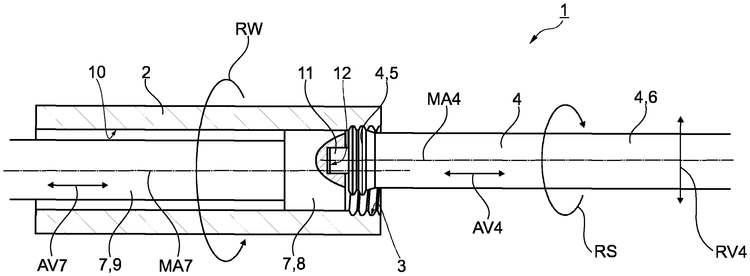
Eine insgesamt mit dem Bezugszeichen 1 gekennzeichnete Fertigungsmaschine ist als Werkzeugmaschine mit Mittenantrieb aufgebaut. Dies bedeutet, dass ein rohrförmiges Werkstück 2 von beiden Seiten her bearbeitet werden kann. Die Fertigungsmaschine 1 wird als Vorrichtung zum Wirbeln eines Innengewindes 3 genutzt. Was die Fertigungstechnologie des Gewindewirbelns im Allgemeinen betrifft, wird auf den eingangs zitierten Stand der Technik verwiesen.A production machine, identified overall by the
Ein Wirbeldorn 4 der Vorrichtung 1 umfasst einen Schneidkopf 5 sowie einen Schaft 6. Der Schneidkopf 5 wird allgemein als Zerspanungswerkzeug bezeichnet. Im vorliegenden Fall ist der Schneidkopf 5 einstückig mit dem Schaft 6 verbunden. Alternativ könnte das Zerspanungswerkzeug 5 beispielsweise in Form von Schneidplatten vorliegen, die direkt oder indirekt am Schaft 6 befestigt sind. Die Mittelachse des Wirbeldorns 4 einschließlich Schneidkopf 5 ist mit MA4 bezeichnet.A whirling
Weiter ist der Vorrichtung 1, das heißt Fertigungsmaschine zum Innengewindewirbeln, ein stabförmiges Führungsteil 7 zuzurechnen. Am Ende des Führungsteils 7 befindet sich ein zylindrischer Führungsabschnitt 8 mit einem im Vergleich zum übrigen Führungsteil 7 vergrößerten Durchmesser. Der Durchmesser des Führungsabschnitts 8 entspricht annähernd dem Innendurchmesser des Werkstücks 2. Der Schaft des Führungsteils 7 ist mit 9 bezeichnet. Ist das Führungsteil 7 in das Werkstück 2 eingeschoben, wie in der Konstellation nach
Das mit der Fertigungsmaschine 1 durchgeführte Zerspanungsverfahren zur Erzeugung des Innengewindes 3 zeichnet sich besonders dadurch aus, dass der Wirbeldorn 4 und das Führungsteil 7 von entgegengesetzten Seiten aus in das Werkstück 2 eingeführt werden, was sowohl aus
Der Wirbeldorn 4 weist einen über den Schneidkopf 5 hinausragenden Zapfen 11 auf, welcher in Zusammenwirkung mit einer als Sacklochbohrung ausgeführten Ausnehmung 12 an der Stirnseite des Führungsabschnitts 8 ein Mittel zur Ausrichtung des Wirbeldorns 4 in Relation zum Führungsteil 7 darstellt. Die Ausnehmung 12 befindet sich exzentrisch im Führungsabschnitt 8. Um den Zapfen 11 in die Ausnehmung 12 einschieben zu können, muss somit der ursprünglich bestehende Radialversatz zwischen dem Zapfen 11 und der Ausnehmung 12 aufgehoben werden. Dies geschieht durch eine mit RV4 bezeichnete Radialverschiebung des Wirbeldorns 4.The whirling
Die spanabhebende Erzeugung des Innengewindes 3 kann entweder von rechts nach links oder von links nach rechts, bezogen auf die Anordnungen nach den
Bezugszeichenlistelist of reference symbols
- 11
- Fertigungsmaschineproduction machine
- 22
- Werkstückworkpiece
- 33
- Innengewindeinternal thread
- 44
- Wirbeldornvertebral spine
- 55
- Schneidkopf, Zerspanungswerkzeugcutting head, cutting tool
- 66
- Schaft des Wirbeldornsshaft of the vertebral spine
- 77
- Führungsteilguide part
- 88
- Führungsabschnittleadership section
- 99
- Schaft des Führungsteilsshaft of the guide part
- 1010
- Innenumfangsflächeinner peripheral surface
- 1111
- Zapfencones
- 1212
- Ausnehmung, Sacklochbohrung recess, blind hole
- AV4AV4
- Axialverschiebung des Wirbeldornsaxial displacement of the vertebral mandrel
- AV7AV7
- Axialverschiebung des Führungsteilsaxial displacement of the guide part
- MA4MA4
- Mittelachse des Wirbeldornscentral axis of the vertebral spine
- MA7MA7
- Mittelachse des Führungsteilscenter axis of the guide part
- RSRS
- Rotation des Schneidkopfesrotation of the cutting head
- RV4RV4
- Radialverschiebung des Wirbeldornsradial displacement of the vertebral spine
- RWRW
- Rotation des Werkstücksrotation of the workpiece
ZITATE ENTHALTEN IN DER BESCHREIBUNGQUOTES INCLUDED IN THE DESCRIPTION
Diese Liste der vom Anmelder aufgeführten Dokumente wurde automatisiert erzeugt und ist ausschließlich zur besseren Information des Lesers aufgenommen. Die Liste ist nicht Bestandteil der deutschen Patent- bzw. Gebrauchsmusteranmeldung. Das DPMA übernimmt keinerlei Haftung für etwaige Fehler oder Auslassungen.This list of documents listed by the applicant was generated automatically and is included solely for the better information of the reader. The list is not part of the German patent or utility model application. The DPMA accepts no liability for any errors or omissions.
Zitierte PatentliteraturCited patent literature
-
EP 1 820 592 A2 [0002]
EP 1 820 592 A2 [0002] - DE 199 22 891 C2 [0004]DE 199 22 891 C2 [0004]
-
DE 1 280 638 A [0005]
DE 1 280 638 A [0005] -
DE 10 2011 110 131 B4 [0006]
DE 10 2011 110 131 B4 [0006]
Claims (10)
Priority Applications (5)
| Application Number | Priority Date | Filing Date | Title |
|---|---|---|---|
| DE102023115583.0A DE102023115583B4 (en) | 2023-06-15 | 2023-06-15 | Device and method for whirling an internal thread |
| KR1020257030056A KR20250142444A (en) | 2023-06-15 | 2024-05-22 | Device and method for turning internal threads |
| CN202480017410.9A CN120897815A (en) | 2023-06-15 | 2024-05-22 | Apparatus and method for cyclone cutting of internal threads |
| PCT/DE2024/100470 WO2024255953A1 (en) | 2023-06-15 | 2024-05-22 | Device and method for whirling an internal thread |
| JP2025555714A JP2026508971A (en) | 2023-06-15 | 2024-05-22 | Apparatus and method for threading female threads |
Applications Claiming Priority (1)
| Application Number | Priority Date | Filing Date | Title |
|---|---|---|---|
| DE102023115583.0A DE102023115583B4 (en) | 2023-06-15 | 2023-06-15 | Device and method for whirling an internal thread |
Publications (2)
| Publication Number | Publication Date |
|---|---|
| DE102023115583A1 true DE102023115583A1 (en) | 2024-12-19 |
| DE102023115583B4 DE102023115583B4 (en) | 2025-02-13 |
Family
ID=91582110
Family Applications (1)
| Application Number | Title | Priority Date | Filing Date |
|---|---|---|---|
| DE102023115583.0A Active DE102023115583B4 (en) | 2023-06-15 | 2023-06-15 | Device and method for whirling an internal thread |
Country Status (5)
| Country | Link |
|---|---|
| JP (1) | JP2026508971A (en) |
| KR (1) | KR20250142444A (en) |
| CN (1) | CN120897815A (en) |
| DE (1) | DE102023115583B4 (en) |
| WO (1) | WO2024255953A1 (en) |
Cited By (1)
| Publication number | Priority date | Publication date | Assignee | Title |
|---|---|---|---|---|
| DE102024124883A1 (en) * | 2024-08-30 | 2026-04-23 | Erwin Junker Maschinenfabrik Gmbh | DEVICE AND METHOD FOR GRINDING INTERNAL CONTOURS ON WORKPIECES |
Citations (5)
| Publication number | Priority date | Publication date | Assignee | Title |
|---|---|---|---|---|
| DE1280638B (en) | 1966-04-30 | 1968-10-17 | Burgsmueller Karl | Device for whirling internal threads |
| DE19922891C2 (en) | 1999-05-19 | 2002-02-28 | Gfe Ges Fuer Fertigungstechnik | Tool holder for thread whirling |
| EP1820592A2 (en) | 2006-02-21 | 2007-08-22 | Burgsmüller GmbH | Device for machining thread-like profiles |
| DE102011110131B4 (en) | 2011-08-15 | 2019-05-02 | Leistritz Produktionstechnik Gmbh | Processing device, in particular whirling device |
| EP3498408A1 (en) * | 2017-12-14 | 2019-06-19 | Mirko Flam | Whirling apparatus, tool mount and device for transmission of a fluid |
-
2023
- 2023-06-15 DE DE102023115583.0A patent/DE102023115583B4/en active Active
-
2024
- 2024-05-22 CN CN202480017410.9A patent/CN120897815A/en active Pending
- 2024-05-22 KR KR1020257030056A patent/KR20250142444A/en active Pending
- 2024-05-22 WO PCT/DE2024/100470 patent/WO2024255953A1/en not_active Ceased
- 2024-05-22 JP JP2025555714A patent/JP2026508971A/en active Pending
Patent Citations (5)
| Publication number | Priority date | Publication date | Assignee | Title |
|---|---|---|---|---|
| DE1280638B (en) | 1966-04-30 | 1968-10-17 | Burgsmueller Karl | Device for whirling internal threads |
| DE19922891C2 (en) | 1999-05-19 | 2002-02-28 | Gfe Ges Fuer Fertigungstechnik | Tool holder for thread whirling |
| EP1820592A2 (en) | 2006-02-21 | 2007-08-22 | Burgsmüller GmbH | Device for machining thread-like profiles |
| DE102011110131B4 (en) | 2011-08-15 | 2019-05-02 | Leistritz Produktionstechnik Gmbh | Processing device, in particular whirling device |
| EP3498408A1 (en) * | 2017-12-14 | 2019-06-19 | Mirko Flam | Whirling apparatus, tool mount and device for transmission of a fluid |
Cited By (1)
| Publication number | Priority date | Publication date | Assignee | Title |
|---|---|---|---|---|
| DE102024124883A1 (en) * | 2024-08-30 | 2026-04-23 | Erwin Junker Maschinenfabrik Gmbh | DEVICE AND METHOD FOR GRINDING INTERNAL CONTOURS ON WORKPIECES |
Also Published As
| Publication number | Publication date |
|---|---|
| WO2024255953A1 (en) | 2024-12-19 |
| KR20250142444A (en) | 2025-09-30 |
| JP2026508971A (en) | 2026-03-13 |
| DE102023115583B4 (en) | 2025-02-13 |
| CN120897815A (en) | 2025-11-04 |
Similar Documents
| Publication | Publication Date | Title |
|---|---|---|
| DE102008013716B4 (en) | Machine tool and method, in particular for turbocharger Verdichterradfräsen | |
| EP3758876B1 (en) | Chamfering tool, chamfering system, gear-cutting machine and method for chamfering toothings | |
| EP1807243A1 (en) | Method for machining rotation pieces | |
| DE102023115583B4 (en) | Device and method for whirling an internal thread | |
| EP4306251B1 (en) | Tool and method for cutting and deburring and/or chamfering a workpiece toothing comprising a plurality of workpiece teeth | |
| DE4021090A1 (en) | MACHINING DEVICE WITH MEANS FOR CHANGING THE RADIAL POSITION OF CUTTING TOOLS | |
| DE1552391A1 (en) | Device for producing profiled bores | |
| EP0513322B1 (en) | Form drilling or turning device | |
| WO1987004959A1 (en) | Adjustable tool-holder in machine-tools for slot milling | |
| EP2477770B1 (en) | Method of turning a rotating workpiece | |
| DE19833363B4 (en) | Method for turning rotational surfaces on workpieces, preferably on crankshafts, and disc-shaped tool for carrying out the method | |
| DE3333243A1 (en) | Multi-spindle automatic lathe | |
| WO2021155998A1 (en) | Tool for installing or removing a tangless helically coiled wire insert | |
| DE10107580B4 (en) | Hob with means for clamping in a machine tool | |
| EP0119236B1 (en) | Automatic multi-spindle lathe | |
| DE102006055417B4 (en) | Tool head for a pipe cutting machine | |
| DE19962792C1 (en) | Method and device for grinding articulated stars | |
| EP3903979A1 (en) | Method of machining the tip diameter of a gear and combination tool for producing a gear | |
| DE3340830C2 (en) | ||
| DE4137923A1 (en) | Polygon turning tool-head for lathe - has hollow spindle passing over work and having cutting tool that is radially adjustable by varying differential speed of positioning drive gear on spindle | |
| DE102021123380B3 (en) | Device and method for machining rotating workpieces | |
| DE102011003536B4 (en) | Tool head for machining an end section of a workpiece | |
| DE202004012067U1 (en) | Cold metal rolling tool for fabrication of symmetrical metal work piece with straight or angled teeth, spiral teeth with grooves, threads or knurled surfaces | |
| DE102007034140A1 (en) | Repair tool for machining of interior cones or outer cones of machine tools e.g. milling machine, drilling machine, has machining face adapted to outline of inner or outer cone | |
| WO2004041464A1 (en) | Tool for the cutting of threads |
Legal Events
| Date | Code | Title | Description |
|---|---|---|---|
| R012 | Request for examination validly filed | ||
| R016 | Response to examination communication | ||
| R018 | Grant decision by examination section/examining division | ||
| R020 | Patent grant now final |