DE102023110311A1 - POWER GENERATING UNIT CELL AND FUEL CELL - Google Patents

POWER GENERATING UNIT CELL AND FUEL CELL Download PDF

Info

Publication number
DE102023110311A1
DE102023110311A1 DE102023110311.3A DE102023110311A DE102023110311A1 DE 102023110311 A1 DE102023110311 A1 DE 102023110311A1 DE 102023110311 A DE102023110311 A DE 102023110311A DE 102023110311 A1 DE102023110311 A1 DE 102023110311A1
Authority
DE
Germany
Prior art keywords
power generation
generation unit
unit cell
holding part
separator
Prior art date
Legal status (The legal status is an assumption and is not a legal conclusion. Google has not performed a legal analysis and makes no representation as to the accuracy of the status listed.)
Pending
Application number
DE102023110311.3A
Other languages
German (de)
Inventor
Kazunori Shibata
Hitoshi Hamada
Kotaro Ikeda
Current Assignee (The listed assignees may be inaccurate. Google has not performed a legal analysis and makes no representation or warranty as to the accuracy of the list.)
Toyota Motor Corp
Original Assignee
Toyota Motor Corp
Priority date (The priority date is an assumption and is not a legal conclusion. Google has not performed a legal analysis and makes no representation as to the accuracy of the date listed.)
Filing date
Publication date
Application filed by Toyota Motor Corp filed Critical Toyota Motor Corp
Publication of DE102023110311A1 publication Critical patent/DE102023110311A1/en
Pending legal-status Critical Current

Links

Images

Classifications

    • HELECTRICITY
    • H01ELECTRIC ELEMENTS
    • H01MPROCESSES OR MEANS, e.g. BATTERIES, FOR THE DIRECT CONVERSION OF CHEMICAL ENERGY INTO ELECTRICAL ENERGY
    • H01M8/00Fuel cells; Manufacture thereof
    • H01M8/02Details
    • H01M8/0271Sealing or supporting means around electrodes, matrices or membranes
    • H01M8/0276Sealing means characterised by their form
    • HELECTRICITY
    • H01ELECTRIC ELEMENTS
    • H01MPROCESSES OR MEANS, e.g. BATTERIES, FOR THE DIRECT CONVERSION OF CHEMICAL ENERGY INTO ELECTRICAL ENERGY
    • H01M8/00Fuel cells; Manufacture thereof
    • H01M8/02Details
    • H01M8/0271Sealing or supporting means around electrodes, matrices or membranes
    • H01M8/0273Sealing or supporting means around electrodes, matrices or membranes with sealing or supporting means in the form of a frame
    • HELECTRICITY
    • H01ELECTRIC ELEMENTS
    • H01MPROCESSES OR MEANS, e.g. BATTERIES, FOR THE DIRECT CONVERSION OF CHEMICAL ENERGY INTO ELECTRICAL ENERGY
    • H01M8/00Fuel cells; Manufacture thereof
    • H01M8/10Fuel cells with solid electrolytes
    • H01M8/1004Fuel cells with solid electrolytes characterised by membrane-electrode assemblies [MEA]
    • HELECTRICITY
    • H01ELECTRIC ELEMENTS
    • H01MPROCESSES OR MEANS, e.g. BATTERIES, FOR THE DIRECT CONVERSION OF CHEMICAL ENERGY INTO ELECTRICAL ENERGY
    • H01M8/00Fuel cells; Manufacture thereof
    • H01M8/10Fuel cells with solid electrolytes
    • H01M2008/1095Fuel cells with polymeric electrolytes
    • YGENERAL TAGGING OF NEW TECHNOLOGICAL DEVELOPMENTS; GENERAL TAGGING OF CROSS-SECTIONAL TECHNOLOGIES SPANNING OVER SEVERAL SECTIONS OF THE IPC; TECHNICAL SUBJECTS COVERED BY FORMER USPC CROSS-REFERENCE ART COLLECTIONS [XRACs] AND DIGESTS
    • Y02TECHNOLOGIES OR APPLICATIONS FOR MITIGATION OR ADAPTATION AGAINST CLIMATE CHANGE
    • Y02EREDUCTION OF GREENHOUSE GAS [GHG] EMISSIONS, RELATED TO ENERGY GENERATION, TRANSMISSION OR DISTRIBUTION
    • Y02E60/00Enabling technologies; Technologies with a potential or indirect contribution to GHG emissions mitigation
    • Y02E60/30Hydrogen technology
    • Y02E60/50Fuel cells

Landscapes

  • Life Sciences & Earth Sciences (AREA)
  • Engineering & Computer Science (AREA)
  • Manufacturing & Machinery (AREA)
  • Sustainable Development (AREA)
  • Sustainable Energy (AREA)
  • Chemical & Material Sciences (AREA)
  • Chemical Kinetics & Catalysis (AREA)
  • Electrochemistry (AREA)
  • General Chemical & Material Sciences (AREA)
  • Fuel Cell (AREA)

Abstract

Eine Stromerzeugungseinheitszelle weist Folgendes auf: eine Membran-Elektroden-Einheit mit einer Elektrolytmembran und Katalysatorschichten, die so angeordnet sind, dass sie die Elektrolytmembran in die Mitte nehmen; einen Träger (23), der so angeordnet ist, dass er die Membran-Elektroden-Einheit umgibt; und ein Paar Separatoren (15, 18), die so angeordnet sind, dass sie die Membran-Elektroden-Einheit und den Träger (23) in die Mitte nehmen. Der Träger (23) weist ein Grundmaterial (23a) und Klebeschichten (23b) auf, die auf beiden Oberflächen des Grundmaterials (23a) aufgestapelt sind. Jeder der Separatoren (15, 18) weist in einem Abschnitt des Separators, der mit einer entsprechenden der Klebeschichten (23b) des Separators (23) verbunden ist, einen Dichtungsteil (25) und einen Halteteil (26) auf. Der Dichtungsteil (25) ist eine glatte Oberfläche, und der Halteteil (26) ist ein Abschnitt mit Unregelmäßigkeiten (26a, 26b).

Figure DE102023110311A1_0000
A power generation unit cell includes: a membrane-electrode assembly having an electrolyte membrane and catalyst layers arranged to center the electrolyte membrane; a support (23) arranged to surround the membrane-electrode assembly; and a pair of separators (15, 18) arranged to center the membrane-electrode assembly and the support (23). The carrier (23) has a base material (23a) and adhesive layers (23b) which are stacked on both surfaces of the base material (23a). Each of the separators (15, 18) has a sealing part (25) and a holding part (26) in a section of the separator which is connected to a corresponding one of the adhesive layers (23b) of the separator (23). The sealing part (25) is a smooth surface, and the holding part (26) is a portion with irregularities (26a, 26b).
Figure DE102023110311A1_0000

Description

HINTERGRUND DER ERFINDUNGBACKGROUND OF THE INVENTION

1. Gebiet der Erfindung1. Field of the invention

Die vorliegende Erfindung bezieht sich auf eine Stromerzeugungseinheitszelle und eine Brennstoffzelle.The present invention relates to a power generation unit cell and a fuel cell.

2. Beschreibung des Stands der Technik2. Description of the prior art

Die JP 2016 - 95 902 A offenbart, dass auf der Klebeseite Vorsprünge in der Form einer Rippe vorgesehen werden, um für eine ausreichende Dicke einer Klebeschicht zu sorgen. Diese Konfiguration kann für eine notwendige Dicke der Klebeschicht besorgen. Die JP 2021 - 012 838 A offenbart, dass auf einen Stapel Stromerzeugungszellen eines Brennstoffzellenstapels in der Stapelrichtung der Stromerzeugungszellen eine Klemmlast aufgebracht wird, dass erste gewellte Vorsprünge außerhalb eines Dichtungswulstabschnitts mit einem ersten Metallseparator als eine Einheit ausgebildet werden, dass zweite gewellte Vorsprünge außerhalb eines Dichtungswulstabschnitts mit einem zweiten Metallseparator als eine Einheit ausgebildet werden und dass jeder der ersten gewellten Abschnitte einen entsprechenden der zweiten gewellten Abschnitte derart überlappt, dass das gewellte Muster der ersten gewellten Vorsprünge und das gewellte Muster der zweiten gewellten Vorsprünge aus der Stapelrichtung gesehen zueinander phasenverschoben sind.The JP 2016 - 95 902 A discloses that projections in the form of a rib are provided on the adhesive side to ensure a sufficient thickness of an adhesive layer. This configuration can provide a necessary thickness of the adhesive layer. The JP 2021 - 012 838 A discloses that a clamping load is applied to a stack of power generation cells of a fuel cell stack in the stacking direction of the power generation cells, that first corrugated projections are formed outside a sealing bead portion with a first metal separator as a unit, that second corrugated projections outside a sealing bead portion are formed with a second metal separator as a unit and that each of the first corrugated sections overlaps a corresponding one of the second corrugated sections such that the corrugated pattern of the first corrugated projections and the corrugated pattern of the second corrugated projections are out of phase with one another as viewed from the stacking direction.

KURZDARSTELLUNG DER ERFINDUNGSUMMARY OF THE INVENTION

Ein Harzrahmen (Träger) ist in einem Außenumfangsabschnitt etc. einer Stromerzeugungszelle vorgesehen und hat die Funktion, die Innenseite der Stromerzeugungszelle abzudichten. Allerdings würde eine Abmessungsänderung des Harzrahmens aufgrund von Wärme und einer Bewegung des Harzrahmens durch eine äußere Kraft etc. wie Druck oder Stoß die Dichtungsleistung, die Haftfestigkeit und die Maßhaltigkeit beeinträchtigen. Bei der in der JP 2016 - 95 902 A beschriebenen Erfindung kann für eine ausreichende Klebedicke gesorgt werden. Wenn die Anzahl der Rippen erhöht wird, bilden sich jedoch tendenziell Räume, etwa Luftblasen. Solche Räume können eine Leckage bewirken oder es kann von den Hohlräumen eine Leckage ausgehen, was zu einer Verringerung der Dichtungsleistung führt. Da die Rippen in einem Abschnitt vorgesehen werden, der Luftdichtheit durch Abdichtung verlangt, kann diese Konfiguration außerdem nicht sowohl für Dichtungsleistung (Auslaufsicherheit) als auch für Maßhaltigkeit sorgen. Die in der JP 2021 - 012 838 A beschriebene Erfindung ist ein Mittel, um durch eine Metallfederdichtung die Aufbringung eines Moments auf einen Schweißabschnitt zu verringern, doch sie kann keine Abmessungsänderung eines Rahmens (Trägers) aufgrund einer Wärmekonzentration, eines Kriechens etc. verringern. Da die gewellten Vorsprünge gewellte Wülste sind, die dazu vorgesehen sind, ein Biegemoment zu verringern, kann nämlich nicht von ihnen erwartet werden, die Bewegung des Rahmens (Trägers) zu verringern.A resin frame (support) is provided in an outer peripheral portion etc. of a power generation cell and has a function of sealing the inside of the power generation cell. However, a dimensional change of the resin frame due to heat and movement of the resin frame by an external force etc. such as pressure or impact would affect the sealing performance, adhesion strength and dimensional stability. At the in the JP 2016 - 95 902 A The invention described can ensure sufficient adhesive thickness. However, as the number of ribs is increased, spaces such as air bubbles tend to form. Such spaces can cause leakage or leakage can originate from the cavities, resulting in a reduction in sealing performance. In addition, since the ribs are provided in a section that requires airtightness through sealing, this configuration cannot provide both sealing performance (leakproof) and dimensional stability. The ones in the JP 2021 - 012 838 A The invention described is a means for reducing application of a moment to a welding portion by a metal spring seal, but it cannot reduce dimensional change of a frame (beam) due to heat concentration, creep, etc. Namely, since the corrugated projections are corrugated beads intended to reduce a bending moment, they cannot be expected to reduce the movement of the frame (beam).

Die vorliegende Erfindung stellt eine Stromerzeugungseinheitszelle mit einem Aufbau zur Verfügung, der sowohl für Dichtungsleistung als auch für Maßhaltigkeit sorgen kann. Die vorliegende Erfindung stellt auch eine Brennstoffzelle zur Verfügung, die diese Stromerzeugungseinheitszelle verwendet.The present invention provides a power generating unit cell having a structure that can provide both sealing performance and dimensional stability. The present invention also provides a fuel cell using this power generation unit cell.

Eine Ausgestaltung der vorliegenden Erfindung sieht eine Stromerzeugungseinheitszelle vor. Diese Stromerzeugungseinheitszelle weist Folgendes auf: eine Membran-Elektroden-Einheit mit einer Elektrolytmembran und Katalysatorschichten, die so angeordnet sind, dass sie die Elektrolytmembran in die Mitte nehmen; einen Träger, der so angeordnet ist, dass er die Membran-Elektroden-Einheit umgibt; und ein Paar Separatoren, die so angeordnet sind, dass sie die Membran-Elektroden-Einheit und den Träger in die Mitte nehmen. Der Träger weist ein Grundmaterial und Klebeschichten auf, die auf beiden Oberflächen des Grundmaterials aufgestapelt sind. Jeder der Separatoren weist in einem Abschnitt des Separators, der mit einer entsprechenden der Klebeschichten des Trägers verbunden ist, einen Dichtungsteil, der eine glatte Oberfläche ist, und einen Halteteil auf, der ein Abschnitt mit Unregelmäßigkeiten ist.One embodiment of the present invention provides a power generation unit cell. This power generation unit cell includes: a membrane-electrode assembly having an electrolyte membrane and catalyst layers arranged to take the electrolyte membrane at the center; a support arranged to surround the membrane-electrode assembly; and a pair of separators arranged to center the membrane-electrode assembly and the carrier. The carrier includes a base material and adhesive layers stacked on both surfaces of the base material. Each of the separators has, in a portion of the separator bonded to a corresponding one of the adhesive layers of the carrier, a sealing portion that is a smooth surface and a holding portion that is a portion having irregularities.

In der Stromerzeugungseinheitszelle der obigen Ausgestaltung kann der Halteteil mit Kämmen versehen sein, die von einer Oberfläche des Halteteils vorstehen, wobei sich die Oberfläche auf der Seite des Trägers befindet und die nebeneinanderliegenden Kämme in Abständen angeordnet sein können.In the power generating unit cell of the above embodiment, the holding part may be provided with combs protruding from a surface of the holding part, the surface being on the support side, and the adjacent combs may be arranged at intervals.

In der Stromerzeugungseinheitszelle der obigen Ausgestaltung kann eine Höhe der Kämme 20 µm oder mehr und 80 µm oder weniger betragen, und der Abstand zwischen den nebeneinanderliegenden Kämmen kann 0,4 mm oder mehr und 1,5 mm oder weniger betragen.In the power generation unit cell of the above embodiment, a height of the combs may be 20 µm or more and 80 µm or less, and the distance between the adjacent combs may be 0.4 mm or more and 1.5 mm or less.

In der Stromerzeugungseinheitszelle der obigen Ausgestaltung kann der Halteteil mit Nuten versehen sein, die von einer Oberfläche des Halteteils zurückgesetzt sind, wobei sich die Oberfläche auf der Seite des Trägers befindet.In the power generating unit cell of the above embodiment, the holding part may be provided with grooves recessed from a surface of the holding part, the surface being on the support side.

In der Stromerzeugungseinheitszelle der obigen Ausgestaltung kann der Halteteil auf einer Oberfläche des Halteteils mit zylinderförmigen Vorsprüngen versehen sein, wobei sich die Oberfläche auf der Seite des Trägers befindet.In the power generation unit cell of the above embodiment, the holding part may be provided on a surface of the holding part with cylindrical projections be provided, with the surface on the side of the carrier.

In der Stromerzeugungseinheitszelle der obigen Ausgestaltung können die Vorsprünge auf eine gestaffelte Weise angeordnet sein.In the power generation unit cell of the above embodiment, the projections may be arranged in a staggered manner.

In der Stromerzeugungseinheitszelle der obigen Ausgestaltung kann der Separator zwischen dem Dichtungsteil und dem Halteteil einen vorstehenden Abschnitt aufweisen.In the power generation unit cell of the above embodiment, the separator may have a protruding portion between the sealing part and the holding part.

In der Stromerzeugungseinheitszelle der obigen Ausgestaltung können der Dichtungsteil und der Halteteil nebeneinanderliegen.In the power generation unit cell of the above embodiment, the sealing part and the holding part may be juxtaposed.

Eine weitere Ausgestaltung der vorliegenden Erfindung sieht eine Brennstoffzelle vor, die sich aus einem Stapel einer Vielzahl der Stromerzeugungseinheitszellen der obigen Ausgestaltung zusammensetzt.A further embodiment of the present invention provides a fuel cell which is composed of a stack of a plurality of the power generation unit cells of the above embodiment.

Gemäß der obigen Erfindung sind getrennt ein Abschnitt, der eine hohe Dichtungsleistung hat, und ein Abschnitt vorgesehen, der die Maßhaltigkeit verbessert, wobei sowohl für eine hohe Dichtungsleistung als auch für eine hohe Maßhaltigkeit gesorgt werden kann.According to the above invention, a portion having high sealing performance and a portion improving dimensional stability are separately provided, whereby both high sealing performance and high dimensional stability can be provided.

KURZE BESCHREIBUNG DER ZEICHNUNGENBRIEF DESCRIPTION OF THE DRAWINGS

Unten werden unter Bezugnahme auf die beigefügten Zeichnungen, in denen gleiche Zeichen gleiche Elemente bezeichnen, die Merkmale, die Vorteile und die technische und gewerbliche Bedeutung exemplarischer Ausführungsbeispiele der Erfindung beschrieben. Es zeigen:

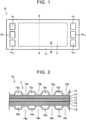
  • 1 eine Draufsicht auf eine Stromerzeugungseinheitszelle;
  • 2 eine Schnittansicht eines Stromerzeugungsabschnitts, der eine Schichtkonfiguration des Stromerzeugungsabschnitts darstellt;
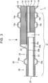
  • 3 eine Schnittansicht eines Außenumfangsabschnitts, der eine Schichtkonfiguration des Außenumfangsabschnitts darstellt;
  • 4 eine vergrößerte Ansicht eines Teils von 3;
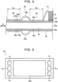
  • 5 eine Draufsicht auf einen Träger;
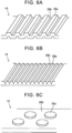
  • 6A ein Beispiel der Form eines Halteteils;
  • 6B ein weiteres Beispiel der Form des Halteteils;
  • 6C noch ein weiteres Beispiel der Form des Halteteils;
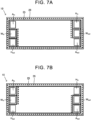
  • 7A ein Schaubild, das die Position eines Dichtungsabschnitts darstellt;
  • 7B ein weiteres Schaubild, das die Position des Dichtungsabschnitts darstellt;
  • 8 ein weiteres Ausführungsbeispiel; und
  • 9 eine Brennstoffzelle.
The features, advantages and technical and industrial significance of exemplary embodiments of the invention will be described below with reference to the accompanying drawings, in which like characters designate like elements. Show it:
  • 1 a top view of a power generation unit cell;
  • 2 a sectional view of a power generation section showing a layer configuration of the power generation section;
  • 3 a sectional view of an outer peripheral portion showing a layer configuration of the outer peripheral portion;
  • 4 an enlarged view of part of 3 ;
  • 5 a top view of a carrier;
  • 6A an example of the shape of a holding part;
  • 6B another example of the shape of the holding part;
  • 6C yet another example of the shape of the holding part;
  • 7A a diagram showing the position of a seal portion;
  • 7B another diagram showing the position of the seal portion;
  • 8th another embodiment; and
  • 9 a fuel cell.

AUSFÜHRLICHE BESCHREIBUNG VON AUSFÜHRUNGSBEISPIELENDETAILED DESCRIPTION OF EMBODIMENTS

1. Stromerzeugungseinheitszelle1. Power generation unit cell

Die 1 bis 3 stellen eine Stromerzeugungseinheitszelle 10 gemäß einem Ausführungsbeispiel dar. Die Stromerzeugungseinheitszelle 10 ist ein Einheitselement zur Erzeugung von Elektrizität, wenn es mit Wasserstoff und Sauerstoff (Luft) versorgt wird, und es wird eine Vielzahl solcher Stromerzeugungseinheitszellen 10 aufeinandergestapelt, um eine Brennstoffzelle auszubilden. 1 ist eine Draufsicht auf die Stromerzeugungseinheitszelle 10, 2 stellt eine Schichtkonfiguration in einem Stromerzeugungsabschnitt 11 der Stromerzeugungseinheitszelle 10 dar, und 3 stellt eine Schichtkonfiguration in einem Außenumfangsabschnitt 21 der Stromerzeugungseinheitszelle 10 dar.The 1 until 3 illustrate a power generation unit cell 10 according to an embodiment. The power generation unit cell 10 is a unit element for generating electricity when supplied with hydrogen and oxygen (air), and a plurality of such power generation unit cells 10 are stacked to form a fuel cell. 1 is a top view of the power generation unit cell 10, 2 illustrates a layer configuration in a power generation section 11 of the power generation unit cell 10, and 3 illustrates a layer configuration in an outer peripheral portion 21 of the power generation unit cell 10.

1.1. Stromerzeugungsabschnitt1.1. Electricity generation section

Der Stromerzeugungsabschnitt 11 ist zum Beispiel ein Abschnitt, wie er durch die gestrichelte Linie in 1 dargestellt ist, der zur Stromerzeugung beiträgt. Der Stromerzeugungsabschnitt 11 setzt sich aus einem Stapel einer Vielzahl von Schichten zusammen, wie durch die Schichtkonfiguration des Stromerzeugungsabschnitts 11 in 2 (Teil eines Schnitts entlang der Linie II-II in 1) gezeigt ist. In dem Stromerzeugungsabschnitt 11 der Stromerzeugungseinheitszelle 10 ist auf einer Seite quer zu einer Elektrolytmembran 10 eine Kathode (Sauerstoffversorgungsseite) angeordnet, und auf der anderen Seite ist eine Anode (Wasserstoffversorgungsseite) angeordnet. Die Kathode weist eine Kathoden-Katalysatorschicht 13, eine Kathoden-Gasdiffusionsschicht 14 und einen Kathoden-Separator 15 auf, die von der Seite der Elektrolytmembran 12 aus in dieser Reihenfolge aufeinandergestapelt sind. Die Anode weist von der Seite der Elektrolytmembran 12 aus eine Anoden-Katalysatorschicht 16, eine Anoden-Gasdiffusionsschicht 17 und einen Anoden-Separator 18 in dieser Reihenfolge auf. Der Stapel der Elektrolytmembran 12, der Kathoden-Katalysatorschicht 13 und der Anoden-Katalysatorschicht 16 (Stapel von Katalysatorschichten mit einer dazwischen angeordneten Elektrolytmembran) wird manchmal eine Membran-Elektroden-Einheit genannt. Eine typische Dicke der Membran-Elektroden-Einheit liegt bei rund 0,4 mm und eine typische Dicke der Stromerzeugungseinheitszelle 10 in dem Stromerzeugungsabschnitt 11 liegt bei rund 1,3 mm. Jede Schicht stellt sich zum Beispiel wie folgt dar.The power generation section 11 is, for example, a section shown by the broken line in FIG 1 is shown, which contributes to electricity generation. The power generation section 11 is composed of a stack of a plurality of layers, as shown by the layer configuration of the power generation section 11 in 2 (Part of a section along line II-II in 1 ) is shown. In the power generation section 11 of the power generation unit cell 10, a cathode (oxygen supply side) is arranged on one side across an electrolyte membrane 10, and an anode (hydrogen supply side) is arranged on the other side. The cathode includes a cathode catalyst layer 13, a cathode gas diffusion layer 14, and a cathode separator 15 stacked in this order from the electrolyte membrane 12 side. The anode includes, from the electrolyte membrane 12 side, an anode catalyst layer 16, an anode gas diffusion layer 17, and an anode separator 18 in this order. The stack of electrolyte membrane 12, cathode catalyst layer 13, and anode catalyst layer 16 (stack of catalyst layers with an electrolyte membrane interposed therebetween) is sometimes called a membrane-electrode assembly. A typical thickness of the membrane-electrode unit is around 0.4 mm and a typical thickness of the power generation unit cell 10 in the power generation section 11 is around 1.3 mm. For example, each layer appears as follows.

1.1.1. Elektrolytmembran1.1.1. Electrolyte membrane

Die Elektrolytmembran 10 ist eine Festpolymer-Elektrolytmembran, die im nassen Zustand zufriedenstellende Protonenleitfähigkeit zeigt. Die Elektrolytmembran 12 ist zum Beispiel eine Fluorionen-Austauschmembran. Als Elektrolytmembran 12 kann zum Beispiel ein Kohlenstoff-Fluor-Polymer verwendet werden. Ein bestimmtes Beispiel für das Kohlenstoff-Fluor-Polymer ist ein Perfluoralkylsulfonsäurenpolymer (Nafion (eingetragene Marke)). Die Dicke der Elektrolytmembran 12 beträgt, ohne darauf besonders beschränkt zu sein, vorzugsweise 200 µm oder weniger, besser 100 µm oder weniger, noch besser 50 µm oder weniger.The electrolyte membrane 10 is a solid polymer electrolyte membrane that exhibits satisfactory proton conductivity when wet. The electrolyte membrane 12 is, for example, a fluorine ion exchange membrane. For example, a carbon-fluorine polymer can be used as the electrolyte membrane 12. A specific example of the carbon-fluorine polymer is a perfluoroalkylsulfonic acid polymer (Nafion (Registered Trademark)). The thickness of the electrolyte membrane 12 is, but is not particularly limited to, preferably 200 μm or less, more preferably 100 μm or less, even more preferably 50 μm or less.

1.1.2. Kathoden-Katalysatorschicht1.1.2. Cathode catalyst layer

Die Kathoden-Katalysatorschicht 13 ist eine Schicht, die ein von einem Träger getragenes Katalysatormetall enthält. Beispiele für das Katalysatormetall sind Platin (Pt), Palladium (Pd), Rhodium (Rh) und Legierungen, die diese enthalten. Beispiele für den Träger sind Kohlenstoffträger, genauer gesagt Kohlenstoffpartikel aus Glaskohlenstoff, Ruß, Aktivkohle, Koks, natürlichem Graphit und künstlichem Graphit.The cathode catalyst layer 13 is a layer containing a catalyst metal supported on a carrier. Examples of the catalyst metal are platinum (Pt), palladium (Pd), rhodium (Rh) and alloys containing them. Examples of the carrier are carbon carriers, more precisely carbon particles made of glassy carbon, soot, activated carbon, coke, natural graphite and artificial graphite.

1.1.3. Anoden-Katalysatorschicht1.1.3. Anode catalyst layer

Wie die Kathoden-Katalysatorschicht 13 ist auch die Anoden-Katalysatorschicht 16 eine Schicht, die ein von einem Träger getragenes Katalysatormetall enthält. Beispiele für das Katalysatormetall sind Pt, Pd, Rh und Legierungen, die diese enthalten. Beispiele für den Träger sind Kohlenstoffträger, insbesondere Kohlenstoffteilchen aus Glaskohlenstoff, Ruß, Aktivkohle, Koks, natürlichem Graphit und künstlichem Graphit.Like the cathode catalyst layer 13, the anode catalyst layer 16 is also a layer containing a catalyst metal supported on a support. Examples of the catalyst metal are Pt, Pd, Rh and alloys containing them. Examples of the carrier are carbon carriers, in particular carbon particles made from glassy carbon, soot, activated carbon, coke, natural graphite and artificial graphite.

1.1.4. Kathoden-Gasdiffusionsschicht1.1.4. Cathode gas diffusion layer

In dem vorliegenden Ausführungsbeispiel ist die Kathoden-Gasdiffusionsschicht 14 eine Schicht aus zum Beispiel einem elektrisch leitenden porösen Material. Konkretere Beispiele für die Kathoden-Gasdiffusionsschicht sind poröse Kohlenstoffmaterialien (etwa Kohlenstoffpapier, Kohlenstofftuch und Glaskohlenstoff) und poröse Metallmaterialien (Metallgewebe und Metallschaum). Die Kathoden-Gasdiffusionsschicht 14 kann bei Bedarf mit einer mikroporösen Lage (MPL) versehen sein. Die MPL ist ein dünner Film in Form eines Überzugs, der auf der Seite der Kathoden-Katalysatorschicht 13 der Kathoden-Gasdiffusionsschicht 14 aufgebracht wird. Die MPL ist bei Bedarf wasserabweisend oder hydrophil und hat die Funktion, die Feuchtigkeit einzustellen. Die MPL dient auch dazu zu verhindern, dass Flaum etc. auf einem porösen Kohlenstoffmaterial in die Elektrolytmembran 12 hineinsticht. Die MPL enthält typischerweise hauptsächlich ein wasserabweisendes Harz wie Polytetrafluorethylen (PTFE) und ein elektrisch leitendes Material wie Ruß.In the present embodiment, the cathode gas diffusion layer 14 is a layer of, for example, an electrically conductive porous material. More specific examples of the cathode gas diffusion layer are porous carbon materials (such as carbon paper, carbon cloth and glassy carbon) and porous metal materials (metal cloth and metal foam). The cathode gas diffusion layer 14 can be provided with a microporous layer (MPL) if necessary. The MPL is a thin film in the form of a coating applied on the cathode catalyst layer 13 side of the cathode gas diffusion layer 14. The MPL is water-repellent or hydrophilic if necessary and has the function of adjusting moisture. The MPL also serves to prevent fuzz, etc. on a porous carbon material from piercing the electrolyte membrane 12. The MPL typically contains primarily a water-repellent resin such as polytetrafluoroethylene (PTFE) and an electrically conductive material such as carbon black.

Die Dicke der Kathoden-Gasdiffusionsschicht 14 im Stromerzeugungsabschnitt 11 beträgt vorzugsweise 50 µm oder mehr und 250 µm oder weniger. Wenn die Dicke der Kathoden-Gasdiffusionsschicht 14 im Stromerzeugungsabschnitt 11 mehr als 250 µm beträgt, nimmt der elektrische Widerstand zu. Wenn die Dicke der Kathoden-Gasdiffusionsschicht 14 im Stromerzeugungsabschnitt 11 weniger als 50 m beträgt, kann die Kathoden-Gasdiffusionsschicht 14 möglicherweise nicht flexibel genug sein, um einen gleichmäßigen Oberflächendruck im Stromerzeugungsabschnitt 11 zu erzielen. Auf den Stromerzeugungsabschnitt 11 wird insbesondere ein Oberflächendruck von 0,2 MPa oder mehr und 2 MPa oder weniger aufgebracht, und es werden die Federeigenschaften (Elastizität) der Kathoden-Gasdiffusionsschicht 14 genutzt, um den Oberflächendruck im Stromerzeugungsabschnitt 11 konstant zu halten.The thickness of the cathode gas diffusion layer 14 in the power generation section 11 is preferably 50 μm or more and 250 μm or less. When the thickness of the cathode gas diffusion layer 14 in the power generation section 11 is more than 250 μm, the electrical resistance increases. If the thickness of the cathode gas diffusion layer 14 in the power generation section 11 is less than 50 m, the cathode gas diffusion layer 14 may not be flexible enough to achieve a uniform surface pressure in the power generation section 11. Specifically, a surface pressure of 0.2 MPa or more and 2 MPa or less is applied to the power generation section 11, and the spring properties (elasticity) of the cathode gas diffusion layer 14 are used to keep the surface pressure in the power generation section 11 constant.

1.1.5. Anoden-Gasdiffusionsschicht1.1.5. Anode gas diffusion layer

Die Anoden-Gasdiffusionsschicht 17 ist eine Schicht aus zum Beispiel einem elektrisch leitenden porösen Material. Konkretere Beispiele für die Anoden-Gasdiffusionsschicht 17 sind poröse Kohlenstoffmaterialien (etwa Kohlenstoffpapier, Kohlenstofftuch und Glaskohlenstoff) und poröse Metallmaterialien (Metallgewebe und Metallschaum).The anode gas diffusion layer 17 is a layer made of, for example, an electrically conductive porous material. More specific examples of the anode gas diffusion layer 17 are porous carbon materials (such as carbon paper, carbon cloth and glassy carbon) and porous metal materials (metal cloth and metal foam).

Die Dicke der Anoden-Gasdiffusionsschicht 17 in dem Stromerzeugungsabschnitt 11 beträgt vorzugsweise 50 µm oder mehr und 250 µm oder weniger. Wenn die Dicke der Anoden-Gasdiffusionsschicht 17 im Stromerzeugungsabschnitt 11 mehr als 250 µm beträgt, nimmt der elektrische Widerstand zu. Wenn die Dicke der Anoden-Gasdiffusionsschicht 17 im Stromerzeugungsabschnitt 11 weniger als 50 µm beträgt, ist die Anoden-Gasdiffusionsschicht 17 möglicherweise nicht flexibel genug, um einen gleichmäßigen Oberflächendruck im Stromerzeugungsabschnitt 11 zu erzielen. Auf den Stromerzeugungsabschnitt 11 wird insbesondere ein Oberflächendruck von 0,2 MPa oder mehr und 2 MPa oder weniger aufgebracht, und es werden die Federeigenschaften (Elastizität) der Anoden-Gasdiffusionsschicht 17 genutzt, um den Oberflächendruck im Stromerzeugungsabschnitt 11 konstant zu halten.The thickness of the anode gas diffusion layer 17 in the power generation section 11 is preferably 50 μm or more and 250 μm or less. When the thickness of the anode gas diffusion layer 17 in the power generation section 11 is more than 250 μm, the electrical resistance increases. If the thickness of the anode gas diffusion layer 17 in the power generation section 11 is less than 50 μm, the anode gas diffusion layer 17 may not be flexible enough to achieve a uniform surface pressure in the power generation section 11. Specifically, a surface pressure of 0.2 MPa or more and 2 MPa or less is applied to the power generation section 11, and the spring properties (elasticity) of the anode gas diffusion layer 17 are used to keep the surface pressure in the power generation section 11 constant.

1.1.6. Kathoden-Separator1.1.6. Cathode separator

Der Kathoden-Separator 15 ist ein Bauteil, das der Kathoden-Gasdiffusionsschicht 14 Reaktionsgas (Luft in diesem Ausführungsbeispiel) zuführt und das auf seiner Oberfläche, die der Kathoden-Gasdiffusionsschicht 14 zugewandt ist, eine Vielzahl von Nuten 15a hat. Die Nute 15a dienen als Reaktionsgaskanäle. Die Form der Nute 15a ist nicht besonders beschränkt, solange das Reaktionsgas der Kathoden-Gasdiffusionsschicht 14 angemessen zugeführt werden kann. Die Nute 15a liegen zum Beispiel wie in diesem Ausführungsbeispiel in der Form von Wellen eines gewellten Plattenbauteils vor. Eine typische Dicke des Plattenbauteils beträgt 0,1 mm oder mehr und 0,2 mm oder weniger, und eine typische Höhe der Wellen des Plattenbauteils liegt bei rund 0,5 mm. Der Kathoden-Separator 15 hat in diesem Fall auf der gegenüberliegenden Seite der Nute 15a Nute 15b. Jede Nut 15b ist zwischen benachbarten Nuten 15a ausgebildet. Die Nute 15b dienen als Kühlmittelkanäle.The cathode separator 15 is a component that reacts to the cathode gas diffusion layer 14 tion gas (air in this embodiment) and which has a plurality of grooves 15a on its surface facing the cathode gas diffusion layer 14. The grooves 15a serve as reaction gas channels. The shape of the groove 15a is not particularly limited as long as the reaction gas can be appropriately supplied to the cathode gas diffusion layer 14. For example, as in this exemplary embodiment, the grooves 15a are in the form of waves of a corrugated plate component. A typical thickness of the plate member is 0.1 mm or more and 0.2 mm or less, and a typical height of the corrugations of the plate member is around 0.5 mm. In this case, the cathode separator 15 has grooves 15b on the opposite side of the groove 15a. Each groove 15b is formed between adjacent grooves 15a. The grooves 15b serve as coolant channels.

Wie in 1 zu erkennen ist, hat der Kathoden-Separator 15 in einem Abschnitt, der sich von dem Stromerzeugungsabschnitt 11 ausdehnt, an Stellen außerhalb des Stromerzeugungsabschnitts 11, und zwar in einem Endabschnitt in der Richtung, in der sich die Nute 15a, 15b erstrecken, einen Lufteinlass Ain, einen Kühlmitteleinlass Win und einen Wasserstoffauslass Hout. Der Kathoden-Separator 15 hat außerdem in einem Abschnitt, der sich von dem Stromerzeugungsabschnitt 11 ausdehnt, an Stellen außerhalb des Stromerzeugungsabschnitts 11, und zwar in dem anderen Endabschnitt in der Richtung, in der sich die Nute 15a, 15b erstrecken, einen Luftauslass Aout, einen Kühlmittelauslass Wout und einen Wasserstoffeinlass Hin. Die Nute 15a kommunizieren mit dem Lufteinlass Ain und dem Luftauslass Aout, während die Nute 15b mit dem Kühlmitteleinlass Win und dem Kühlmittelauslass Wout kommunizieren.As in 1 As can be seen, the cathode separator 15 has an air inlet in a portion extending from the power generation portion 11 at locations outside the power generation portion 11, namely, in an end portion in the direction in which the grooves 15a, 15b extend A in , a coolant inlet W in and a hydrogen outlet H out . The cathode separator 15 also has an air outlet A out in a portion extending from the power generation portion 11 at positions outside the power generation portion 11, namely, in the other end portion in the direction in which the grooves 15a, 15b extend , a coolant outlet W out and a hydrogen inlet H in . The grooves 15a communicate with the air inlet A in and the air outlet A out , while the grooves 15b communicate with the coolant inlet W in and the coolant outlet W out .

Der Kathoden-Separator 15 kann aus einem beliebigen Material bestehen, das als ein Separator für eine Stromerzeugungseinheitszelle verwendet werden kann, und er kann aus einem gasundurchlässigen, elektrisch leitenden Material bestehen. Beispiele für ein solches Material sind gasundurchlässiger dichter Kohlenstoff, der durch Verdichten von Kohlenstoff hergestellt wurde, und pressgeformte Metallplatten.The cathode separator 15 may be made of any material that can be used as a separator for a power generation unit cell, and may be made of a gas-impermeable electrically conductive material. Examples of such a material are gas-impermeable dense carbon made by compacting carbon and press-formed metal plates.

1.1.7. Anoden-Separator1.1.7. Anode separator

Der Anoden-Separator 18 ist ein Bauteil, der der Anoden-Gasdiffusionsschicht 17 Reaktionsgas (Wasserstoff) zuführt und auf seiner Oberfläche, die der Anoden-Gasdiffusionsschicht 17 zugewandt ist, eine Vielzahl von Nuten 18a hat. Die Nute 18a dienen als Reaktionsgaskanäle. Die Form der Nute 18a ist nicht besonders beschränkt, solange das Reaktionsgas der Anoden-Gasdiffusionsschicht 17 angemessen zugeführt werden kann. Die Nute 18a liegen zum Beispiel wie in diesem Ausführungsbeispiel in der Form von Wellen eines gewellten Plattenbauteils vor. Eine typische Dicke des Plattenbauteils beträgt 0,1 mm oder mehr und 0,2 mm oder weniger, und eine typische Höhe der Wellen des Plattenbauteils liegt bei rund 0,4 mm. Der Anoden-Separator 18 hat in diesem Fall auf der gegenüberliegenden Seite von den Nuten 18a Nute 18b. Jede Nut 18b ist zwischen benachbarten Nuten 18a ausgebildet. Die Nute 18b dienen als Kühlmittelkanäle.The anode separator 18 is a member that supplies reaction gas (hydrogen) to the anode gas diffusion layer 17 and has a plurality of grooves 18a on its surface facing the anode gas diffusion layer 17. The grooves 18a serve as reaction gas channels. The shape of the groove 18a is not particularly limited as long as the reaction gas can be adequately supplied to the anode gas diffusion layer 17. For example, as in this exemplary embodiment, the grooves 18a are in the form of waves of a corrugated plate component. A typical thickness of the plate member is 0.1 mm or more and 0.2 mm or less, and a typical height of the corrugations of the plate member is around 0.4 mm. In this case, the anode separator 18 has grooves 18b on the opposite side of the grooves 18a. Each groove 18b is formed between adjacent grooves 18a. The grooves 18b serve as coolant channels.

Wie in 1 zu erkennen ist, hat der Anoden-Separator 18 in einem Abschnitt, der sich von dem Stromerzeugungsabschnitt 11 ausdehnt, an Stellen außerhalb des Stromerzeugungsabschnitts 11, und zwar in einem Endabschnitt in der Richtung, in der sich die Nute 18a, 18b erstrecken, einen Lufteinlass Ain, einen Kühlmitteleinlass Win und einen Wasserstoffauslass Hout. Der Anoden-Separator 18 hat außerdem in einem Abschnitt, der sich von dem Stromerzeugungsabschnitt 11 ausdehnt, an Stellen außerhalb des Stromerzeugungsabschnitts 11, und zwar in dem anderen Endabschnitt in der Richtung, in der sich die Nute 18a, 18b erstrecken, einen Luftauslass Aout, einen Kühlmittelauslass Wout und einen Wasserstoffeinlass Hin. Die Nute 18a kommunizieren mit dem Wasserstoffeinlass Hin und dem Wasserstoffauslass Hout, während die Nute 18b mit dem Kühlmitteleinlass Win und dem Kühlmittelauslass Wout kommunizieren.As in 1 As can be seen, the anode separator 18 has an air inlet in a portion extending from the power generation portion 11 at locations outside the power generation portion 11, namely, in an end portion in the direction in which the grooves 18a, 18b extend A in , a coolant inlet W in and a hydrogen outlet H out . The anode separator 18 also has an air outlet A out in a portion extending from the power generation portion 11 at locations outside the power generation portion 11, namely, in the other end portion in the direction in which the grooves 18a, 18b extend , a coolant outlet W out and a hydrogen inlet H in . The grooves 18a communicate with the hydrogen inlet H in and the hydrogen outlet H out , while the grooves 18b communicate with the coolant inlet W in and the coolant outlet W out .

Der Anoden-Separator 18 kann aus einem beliebigen Material bestehen, das als ein Separator für eine Stromerzeugungseinheitszelle verwendet werden kann, und er kann aus einem gasundurchlässigen, elektrisch leitenden Material bestehen. Beispiele für ein solches Material sind gasundurchlässiger dichter Kohlenstoff, der durch Verdichten von Kohlenstoff hergestellt wurde, und pressgeformte Metallplatten.The anode separator 18 may be made of any material that can be used as a separator for a power generation unit cell, and may be made of a gas-impermeable, electrically conductive material. Examples of such a material are gas-impermeable dense carbon made by compacting carbon and press-formed metal plates.

1.1.8. Stromerzeugung durch Stromerzeugungsabschnitt1.1.8. Electricity generation by electricity generation section

Wie auf dem Gebiet bekannt ist, erzeugt die oben beschriebene Stromerzeugungseinheitszelle 10 wie folgt Elektrizität. Wasserstoff, der den Nuten 18a des Anoden-Separators 18 aus dem Wasserstoffeinlass Hin zugeführt wird, geht durch die Anoden-Gasdiffusionsschicht 17 und wird in der Anoden-Katalysatorschicht 16 in Protonen (H+) und Elektronen (e-) zersetzt. Die Protonen erreichen durch die Elektrolytmembran 12 die Kathoden-Katalysatorschicht 13, und die Elektronen erreichen durch einen leitenden Draht, der zur Außenseite führt, die Kathoden-Katalysatorschicht 13. Der übrige Wasserstoff wird aus dem Wasserstoffauslass Hout abgegeben. Der Kathoden-Katalysatorschicht 13 wird aus dem Lufteinlass Ain durch die Nute 15a des Kathoden-Separators 15 und die Kathoden-Gasdiffusionsschicht 14 Sauerstoff (Luft) zugeführt. In der Kathoden-Katalysatorschicht 13 wird durch die Protonen, die Elektronen und den Sauerstoff Wasser (H2O) erzeugt. Das erzeugte Wasser und die übrige Luft gehen durch die Kathoden-Gasdiffusionsschicht 14, erreichen die Nute 15a des Kathoden-Separators 15 und werden aus dem Luftauslass Aout abgegeben. In der Stromerzeugungseinheitszelle 10 wird der Strom der Elektronen durch den leitenden Draht, der sich von der Anoden-Katalysatorschicht 16 zur Außenseite erstreckt, als ein Strom genutzt.As is known in the art, the power generating unit cell 10 described above generates electricity as follows. Hydrogen supplied to the grooves 18a of the anode separator 18 from the hydrogen inlet H in passes through the anode gas diffusion layer 17 and is decomposed into protons (H + ) and electrons (e - ) in the anode catalyst layer 16. The protons reach the cathode catalyst layer 13 through the electrolyte membrane 12, and the electrons reach the cathode catalyst layer 13 through a conductive wire leading to the outside. The remaining hydrogen is discharged from the hydrogen outlet H out . The cathode catalyst layer 13 is drawn from the air inlet A in through the groove 15a of the cathode separator 15 and the cathode gas diffusion layer 14 oxygen (air) supplied. Water (H 2 O) is generated in the cathode catalyst layer 13 by the protons, electrons and oxygen. The generated water and remaining air pass through the cathode gas diffusion layer 14, reach the groove 15a of the cathode separator 15, and are discharged from the air outlet A out . In the power generation unit cell 10, the flow of electrons through the conductive wire extending from the anode catalyst layer 16 to the outside is used as a current.

Wenn eine Brennstoffzelle ausgebildet wird, wird eine Vielzahl von Stromerzeugungseinheitszellen 10 derart aufeinandergestapelt, dass sich der Kathoden-Separator 15 von einer von benachbarten der Stromerzeugungseinheitszellen 10 unter dem Anoden-Separator 18 der anderen Stromerzeugungseinheitszelle 10 befindet. Die Nute 15b des Kathoden-Separators 15 und die Nute 18b des Anoden-Separators 18 bilden somit Kühlmittelkanäle aus. Den Kühlmittelkanälen wird aus dem Kühlmitteleinlass Win ein Kühlmittel zugeführt. Das zugeführte Kühlmittel kühlt die Stromerzeugungseinheitszelle 10 und wird aus dem Kühlmittelauslass Wout abgegeben.When a fuel cell is formed, a plurality of power generation unit cells 10 are stacked such that the cathode separator 15 of one of adjacent ones of the power generation unit cells 10 is located under the anode separator 18 of the other power generation unit cell 10. The groove 15b of the cathode separator 15 and the groove 18b of the anode separator 18 thus form coolant channels. The coolant channels are supplied with coolant from the coolant inlet W. The supplied coolant cools the power generation unit cell 10 and is discharged from the coolant outlet W out .

1.2. Außenumfangsabschnitt1.2. Outer peripheral section

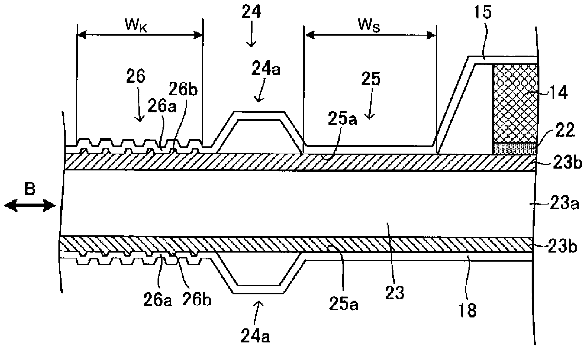
Der Außenumfangsabschnitt 21 ist ein Abschnitt außerhalb des Stromerzeugungsabschnitts 11, wie er durch die gestrichelte Linie in 1 umschlossen gezeigt ist, und er ist ein Außenumfangsabschnitt der Stromerzeugungseinheitszelle 10. Der Außenumfangsabschnitt 21 setzt sich aus einem Stapel einer Vielzahl von Schichten zusammen, wie durch die Schichtkonfiguration des Außenumfangsabschnitts 21 in 3 (Teil eines Schnitts entlang der Linie III-III in 1) gezeigt ist. 4 ist eine vergrößerte Ansicht eines Teils von 3.The outer peripheral portion 21 is a portion outside the power generation portion 11 as indicated by the broken line in FIG 1 is shown enclosed, and is an outer peripheral portion of the power generation unit cell 10. The outer peripheral portion 21 is composed of a stack of a plurality of layers as shown by the layer configuration of the outer peripheral portion 21 in FIG 3 (Part of a section along line III-III in 1 ) is shown. 4 is an enlarged view of a portion of 3 .

1.2.1. Grundaufbau Außenumfangsabschnitt1.2.1. Basic structure of the outer peripheral section

Wie in den 3 und 4 zu erkennen ist, hat in diesem Ausführungsbeispiel zumindest ein Teil des Außenumfangsabschnitts 21 die folgende Konfiguration. Die Elektrolytmembran 12, die Anoden-Katalysatorschicht 16 und die Anoden-Gasdiffusionsschicht 17 sind derart aufeinandergestapelt, dass ihre Stirnflächen ungefähr aneinander ausgerichtet sind. Die Kathoden-Katalysatorschicht 13 ist derart aufgestapelt, dass sich ihre Stirnfläche an einer Stelle einwärts (zurückgezogen) von einer Stirnfläche der Elektrolytmembran 12 befindet. Eine Endfläche der Kathoden-Gasdiffusionsschicht 14 befindet sich an einer Stelle außerhalb (vorgedrungen) von der Stirnfläche der Elektrolytmembran 12. Die Kathoden-Gasdiffusionsschicht 14 erstreckt sich zu solch einer Stelle, dass die Kathoden-Gasdiffusionsschicht 14 in Draufsicht auf die Stromerzeugungseinheitszelle 10 (aus einem Blickwinkel in Richtung von 1, einer Sichtlinie in der Richtung, die durch den Pfeil Z in 3 angegeben wird) einen Träger 23 überlappt. Der Träger 23 wird später beschrieben.Like in the 3 and 4 As can be seen, in this embodiment, at least a part of the outer peripheral portion 21 has the following configuration. The electrolyte membrane 12, the anode catalyst layer 16 and the anode gas diffusion layer 17 are stacked on top of one another in such a way that their end faces are approximately aligned with one another. The cathode catalyst layer 13 is stacked such that its end face is located at a location inward (retracted) from an end face of the electrolyte membrane 12. An end face of the cathode gas diffusion layer 14 is located at a location outside (protruded) from the end face of the electrolyte membrane 12. The cathode gas diffusion layer 14 extends to such a location that the cathode gas diffusion layer 14 is in plan view of the power generation unit cell 10 (made of a Viewpoint in the direction of 1 , a line of sight in the direction indicated by arrow Z in 3 is specified) overlaps a carrier 23. The carrier 23 will be described later.

Auch in dem Außenumfangsabschnitt 21 sind der Kathoden-Separator 15 und der Anoden-Separator 18 so angeordnet, dass sie wie in dem Stromerzeugungsabschnitt 11 die oben beschriebenen Schichten dazwischen in die Mitte nehmen. In dem Außenumfangsabschnitt 21 sind die Außenumfangsabschnitte des Kathoden-Separators 15 und des Anoden-Separators 18 so verlängert, dass sie über die Stirnflächen der Membran-Elektroden-Einheit, der Kathoden-Gasdiffusionsschicht 14 und der Anoden-Gasdiffusionsschicht 17 hinaus vorstehen. Der Träger 23 ist zwischen den verlängerten Abschnitten der Außenumfangsabschnitte des Kathoden-Separators 15 und Anoden-Separators 18 angeordnet. Der Kathoden-Separator 15 und der Anoden-Separator 18 benötigen in dem Außenumfangsabschnitt 21 keine Strömungskanäle. Daher haben der Kathoden-Separator 15 und der Anoden-Separator 18 im Außenumfangsabschnitt 21 keine Nute 15a, 18a. (Wie jedoch in 3 zu erkennen ist, schließt die vorliegende Erfindung keine Konfiguration aus, in der der Kathoden-Separator 15 und der Anoden-Separator 18 in einem Teil des Außenumfangsabschnitts 21 die Nute 15a, 18a haben.) Das heißt, dass in der Stromerzeugungseinheitszelle 10 im Stromerzeugungsabschnitt 11 der Stapel mit der Membran-Elektroden-Einheit zwischen einem Paar Separatoren (dem Kathoden-Separator 15 und Anoden-Separator 18) eingebettet ist und dass im Außenumfangsabschnitt 21 der Träger 23 zwischen dem Paar Separatoren eingebettet ist.Also in the outer peripheral portion 21, the cathode separator 15 and the anode separator 18 are arranged to center the above-described layers therebetween, as in the power generation portion 11. In the outer peripheral portion 21, the outer peripheral portions of the cathode separator 15 and the anode separator 18 are elongated to protrude beyond the end surfaces of the membrane electrode unit, the cathode gas diffusion layer 14 and the anode gas diffusion layer 17. The carrier 23 is disposed between the extended portions of the outer peripheral portions of the cathode separator 15 and anode separator 18. The cathode separator 15 and the anode separator 18 do not require any flow channels in the outer peripheral section 21. Therefore, the cathode separator 15 and the anode separator 18 do not have a groove 15a, 18a in the outer peripheral portion 21. (However, as in 3 As can be seen, the present invention does not exclude a configuration in which the cathode separator 15 and the anode separator 18 have the grooves 15a, 18a in a part of the outer peripheral portion 21. That is, in the power generation unit cell 10 in the power generation portion 11 the stack with the membrane-electrode assembly is embedded between a pair of separators (the cathode separator 15 and anode separator 18) and that in the outer peripheral portion 21 the carrier 23 is embedded between the pair of separators.

Ein Deckblatt 22 ist so angeordnet, dass es einen Endabschnitt einer kathodenseitigen Oberfläche des Trägers 23 und einen Endabschnitt einer kathodenseitigen Oberfläche der Membran-Elektroden-Einheit verbindet. Das Deckblatt 22 wird später beschrieben.A cover sheet 22 is arranged to connect an end portion of a cathode-side surface of the carrier 23 and an end portion of a cathode-side surface of the membrane-electrode assembly. The cover sheet 22 will be described later.

1.2.2. Träger1.2.2. carrier

Der Träger 23 fungiert als ein Bauteil, das in dem Außenumfangsabschnitt 21 der Stromerzeugungseinheitszelle 10 für eine Abdichtung zwischen dem Kathoden-Separator 15 und dem Anoden-Separator 18 sorgt. 5 zeigt eine Draufsicht auf den Träger 23 (aus dem gleichen Blickwinkel wie in 1). Wie in 5 zu erkennen ist, ist der Träger 23 ein hohles Rahmenbauteil, das einen Lufteinlass Ain, einen Kühlmitteleinlass Win, einen Wasserstoffauslass Hout, einen Luftauslass Aout, einen Kühlmittelauslass Wout, einen Wasserstoffeinlass Hin und ein Loch in einem dem Stromerzeugungsabschnitt 11 entsprechenden Abschnitt 23d hat.The carrier 23 functions as a member that provides sealing between the cathode separator 15 and the anode separator 18 in the outer peripheral portion 21 of the power generation unit cell 10. 5 shows a top view of the carrier 23 (from the same angle as in 1 ). As in 5 As can be seen, the carrier 23 is a hollow frame member having an air inlet A in , a coolant inlet W in , a hydrogen outlet H out , an air outlet A out , a coolant outlet W out , a hydrogen inlet H in and a hole in one of the power generation section 11 corresponding section 23d.

Der Träger 23 weist ein Grundmaterial 23a und Klebeschichten 23b auf, die sich auf beiden Oberflächen (der kathodenseitigen Oberfläche und der anodenseitigen Oberfläche) des Grundmaterials 23a befinden. Die Klebeschichten 23b sind mit dem Kathoden-Separator 15 und dem Anoden-Separator 18 verbunden, um den Stromerzeugungsabschnitt 11 zwischen dem Paar Separatoren abzudichten. Es gibt eine Biegung, sodass sich der Abstand zwischen dem Kathoden-Separator 15 und dem Anoden-Separator 18 abhängig von der/den dazwischen angeordneten Schicht(en) ändert. Wie in den 3 und 4 zu erkennen ist, verringert sich dieser Abstand in einem Teil des Abschnitts, in dem sich der Träger 23 zwischen dem Kathoden-Separator 15 und dem Anoden-Separator 18 befindet. In diesem Teil ist der Träger 23 zwischen dem Kathoden-Separator 15 und dem Anoden-Separator 18 (dem Paar Separatoren) eingebettet und befestigt, und dieser Teil dient als ein Dichtungsabschnitt 24. Der Dichtungsabschnitt 24 wird später beschrieben.The carrier 23 includes a base material 23a and adhesive layers 23b located on both surfaces (the cathode-side surface and the anode-side surface) of the base material 23a. The adhesive layers 23b are bonded to the cathode separator 15 and the anode separator 18 to seal the power generation portion 11 between the pair of separators. There is a bend so that the distance between the cathode separator 15 and the anode separator 18 changes depending on the layer(s) therebetween. Like in the 3 and 4 can be seen, this distance decreases in part of the section in which the carrier 23 is located between the cathode separator 15 and the anode separator 18. In this part, the carrier 23 is embedded and fixed between the cathode separator 15 and the anode separator 18 (the pair of separators), and this part serves as a sealing portion 24. The sealing portion 24 will be described later.

Das Grundmaterial 23a besteht aus einem elektrisch isolierenden, luftdichten Material. Beispiele für solch ein Material sind kristalline Polymere, insbesondere technische Kunststoffe. Beispiele für technische Kunststoffe sind Polyethylennaphthalat (PEN)-Harze und Polyethylenterephthalat (PET)-Harze, Polyphenylether (PPE), Polyphenylsulfon (PPSU), Polysulfon (PSU), Polyethersulfon (PES), Polyetheretherketon (PEEK), Polyimid (PI), Polyetherimid (PEI), Polyamidimid (PAI), Polyphenylsulfid (PPS), syndiotaktisches Polystyrol (SPS) und Nylonharze. Die Dicke des Grundmaterials 23a beträgt vorzugsweise, ohne darauf besonders beschränkt zu sein, 0,05 mm oder mehr und 0,25 mm oder weniger.The base material 23a consists of an electrically insulating, airtight material. Examples of such a material are crystalline polymers, especially engineering plastics. Examples of engineering plastics are polyethylene naphthalate (PEN) resins and polyethylene terephthalate (PET) resins, polyphenyl ether (PPE), polyphenyl sulfone (PPSU), polysulfone (PSU), polyether sulfone (PES), polyether ether ketone (PEEK), polyimide (PI), polyetherimide (PEI), polyamideimide (PAI), polyphenyl sulfide (PPS), syndiotactic polystyrene (SPS) and nylon resins. The thickness of the base material 23a is preferably, but not particularly limited to, 0.05 mm or more and 0.25 mm or less.

Für die Klebeschichten 23b können bekannte Materialien verwendet werden, solange sie im Verbindungszustand Klebeeigenschaften zeigen. Beispiele für das Klebematerial, das für die Klebeschichten 23b verwendet wird, sind Polyolefinpolymere, die Maleinsäure oder Maleinsäureanhydrid enthalten. Ein konkreteres Beispiel des Klebermaterials ist ADMER (eingetragene Marke, Mitsui Chemicals, Inc.) Die Dicke der Klebeschichten 23b beträgt vorzugsweise, ohne darauf besonders beschränkt zu sein, 30 µm oder mehr und 50 µm oder weniger.Known materials can be used for the adhesive layers 23b as long as they exhibit adhesive properties in the connected state. Examples of the adhesive material used for the adhesive layers 23b are polyolefin polymers containing maleic acid or maleic anhydride. A more concrete example of the adhesive material is ADMER (registered trademark, Mitsui Chemicals, Inc.). The thickness of the adhesive layers 23b is preferably, but not particularly limited to, 30 μm or more and 50 μm or less.

Ein solcher rahmenförmiger Träger 23 ist so angeordnet, dass er den Stapel in dem Stromerzeugungsabschnitt 11 einschließlich der Membran-Elektroden-Einheit umgibt. Wie in 3 zu erkennen ist, ist der Träger 23 derart angeordnet, dass eine Stirnfläche des Trägers 23 den Stirnflächen der Membran-Elektroden-Einheit und der Anoden-Gasdiffusionsschicht 17 mit einem Raum A dazwischen zugewandt ist. Dieser Raum A kann Abmessungsänderungen des Trägers 23, der Membran-Elektroden-Einheit etc. aufgrund ihrer linearen Ausdehnung absorbieren und die Möglichkeit einer Beschädigung durch Expansion und Kontraktion verringern. Insbesondere beträgt die Entfernung des Raums A in der Richtung, in der der Träger 23 der Membran-Elektroden-Einheit und der Anoden-Gasdiffusionsschicht 17 zugewandt ist, vorzugsweise 0,01 mm oder mehr und 2 mm oder weniger. Wenn die Entfernung weniger als 0,01 mm beträgt, fällt es dem Raum A schwer, eine Abmessungsänderung des Trägers 23 zu absorbieren. Wenn die Entfernung größer als 2 mm ist, kann der Differenzdruck zwischen dem Raum A und der Kathoden-Gasdiffusionsschicht 14 eine Verformung oder eine Beschädigung des Trägers 23 bewirken, was zu einer Verringerung der Dichtungsleistung führt.Such a frame-shaped support 23 is arranged to surround the stack in the power generation section 11 including the membrane-electrode assembly. As in 3 can be seen, the carrier 23 is arranged such that an end face of the carrier 23 faces the end faces of the membrane electrode unit and the anode gas diffusion layer 17 with a space A in between. This space A can absorb dimensional changes of the support 23, the membrane-electrode assembly, etc. due to their linear expansion and reduce the possibility of damage due to expansion and contraction. Specifically, the distance of the space A in the direction in which the support 23 faces the membrane electrode assembly and the anode gas diffusion layer 17 is preferably 0.01 mm or more and 2 mm or less. When the distance is less than 0.01 mm, the space A finds it difficult to absorb a dimensional change of the beam 23. If the distance is larger than 2 mm, the differential pressure between the space A and the cathode gas diffusion layer 14 may cause deformation or damage to the support 23, resulting in a reduction in sealing performance.

1.2.3. Deckblatt1.2.3. cover sheet

Wie oben beschrieben wurde, ist das Deckblatt 22 so angeordnet, dass es den Endabschnitt der kathodenseitigen Oberfläche des Trägers 23 und den Endabschnitt der kathodenseitigen Oberfläche der Membran-Elektroden-Einheit verbindet.As described above, the cover sheet 22 is arranged to connect the end portion of the cathode-side surface of the support 23 and the end portion of the cathode-side surface of the membrane-electrode assembly.

Das Deckblatt 23 ist derart angeordnet, dass ein Endabschnitt des Deckblatts 22 den Endabschnitt der kathodenseitigen Oberfläche des Trägers 23 bedeckt und der andere Endabschnitt des Deckblatts 22 einen Endabschnitt einer Oberfläche der Elektrolytmembran 12 und/oder der Kathoden-Katalysatorschicht 13 der Membran-Elektroden-Einheit bedeckt. (In diesem Ausführungsbeispiel ist das Deckblatt 22 so angeordnet, dass es die Endabschnitte der Oberflächen von sowohl der Elektrolytmembran 12 als auch der Kathoden-Katalysatorschicht 13 bedeckt.) Die Kathode und die Anode können somit im Außenumfangsabschnitt 21 angemessen getrennt werden. Dementsprechend befindet sich das Deckblatt 22 zwischen der Membran-Elektroden-Einheit und der Kathoden-Gasdiffusionsschicht 14 im Endabschnitt der Membran-Elektroden-Einheit.The cover sheet 23 is arranged such that one end portion of the cover sheet 22 covers the end portion of the cathode-side surface of the carrier 23 and the other end portion of the cover sheet 22 covers an end portion of a surface of the electrolyte membrane 12 and/or the cathode catalyst layer 13 of the membrane-electrode unit covered. (In this embodiment, the cover sheet 22 is arranged to cover the end portions of the surfaces of both the electrolyte membrane 12 and the cathode catalyst layer 13.) The cathode and the anode can thus be adequately separated in the outer peripheral portion 21. Accordingly, the cover sheet 22 is located between the membrane-electrode assembly and the cathode gas diffusion layer 14 in the end portion of the membrane-electrode assembly.

Für das Deckblatt 22 wird ein Material verwendet, das für die Reaktionsgase der Brennstoffzelle undurchlässig ist. Beispiele für ein Bauteil, das für die Reaktionsgase undurchlässig ist, sind Filmbauteile aus einem Harz wie Polypropylen, Polyphenylensulfid, Polyethylennaphthalat, Nylon oder EthylenVinylalkohol-Copolymer. Unter dem Gesichtspunkt der Hydrolysebeständigkeit und Haftung an der Elektrolytmembran 12 können insbesondere Nylon 11, Nylon 12, Nylon 9T oder Ethylenvinylalkohol verwendet werden. Um die Haftung an der Elektrolytmembran 12 zu verbessern, kann zum Beispiel ein Zusatzstoff mit einer Amidgruppe, einer Epoxidgruppe, einer Hydroxylgruppe etc. zugegeben werden.A material is used for the cover sheet 22 that is impermeable to the reaction gases of the fuel cell. Examples of a component that is impermeable to the reaction gases are film components made of a resin such as polypropylene, polyphenylene sulfide, polyethylene naphthalate, nylon or ethylene vinyl alcohol copolymer. In particular, from the viewpoint of hydrolysis resistance and adhesion to the electrolyte membrane 12, nylon 11, nylon 12, nylon 9T or ethylene vinyl alcohol can be used. In order to improve the adhesion to the electrolyte membrane 12, for example, an additive having an amide group, an epoxy group, a hydroxyl group, etc. may be added.

Ein Überlappungsabschnitt des Deckblatts 22 mit dem Träger 23 ist durch die Klebeschicht 23b des Trägers 23 mit dem Träger 23 verbunden. Ein Überlappungsabschnitt des Deckblatts 22 mit der Membran-Elektroden-Einheit ist mit der Membran-Elektroden-Einheit durch eine Klebeschicht verbunden, die bei Bedarf auf dem Deckblatt 22 vorgesehen wird. Wenn allerdings Nylon als das Deckblatt 22 verwendet wird, kann die Klebeschicht weggelassen werden, da das Deckblatt 22 und die Membran-Elektroden-Einheit miteinander durch Thermokompressionskleben verbunden werden können.An overlapping portion of the cover sheet 22 with the carrier 23 is connected to the carrier 23 by the adhesive layer 23b of the carrier 23. An overlapping portion of the cover sheet 22 with the membrane-electrode assembly is connected to the membrane-electrode assembly by an adhesive layer provided on the cover sheet 22 as needed. However, when nylon is used as the cover sheet 22, the adhesive layer can be omitted since the cover sheet 22 and the membrane-electrode assembly can be bonded together by thermocompression bonding.

1.2.4. Dichtungsabschnitt1.2.4. sealing section

In dem Dichtungsabschnitt 24 befindet sich zwischen dem Kathoden-Separator 15 und dem Anoden-Separator 18 nur der Träger 23, und der Träger 23 ist zwischen dem Kathoden-Separator 15 und dem Anoden-Separator 18 zur Abdichtung eingebettet und befestigt. Der Dichtungsabschnitt 24 ist so konfiguriert, dass er durch die Formen des Kathoden-Separators 15, des Anoden-Separators 18 und des Trägers 23 eine Abdichtung vornimmt. Dies wird unten ausführlich beschrieben.In the sealing portion 24, only the carrier 23 is located between the cathode separator 15 and the anode separator 18, and the carrier 23 is embedded and fixed between the cathode separator 15 and the anode separator 18 for sealing. The sealing portion 24 is configured to seal by the shapes of the cathode separator 15, the anode separator 18 and the carrier 23. This is described in detail below.

Wie in den 3 und 4 zu erkennen ist, weist der Dichtungsabschnitt 24 in diesem Ausführungsbeispiel einen Dichtungsteil 25 und einen Halteteil 26 auf. Der Kathoden-Separator 15 und der Anoden-Separator 18 haben in diesem Ausführungsbeispiel jeweils einen vorstehenden Abschnitt 24a zwischen dem Dichtungsteil 25 und dem Halteteil 26.Like in the 3 and 4 As can be seen, the sealing section 24 in this exemplary embodiment has a sealing part 25 and a holding part 26. In this exemplary embodiment, the cathode separator 15 and the anode separator 18 each have a projecting section 24a between the sealing part 25 and the holding part 26.

DichtungsteilSealing part

Der Dichtungsteil 25 ist ein Abschnitt, in dem Oberflächen 25a des Kathoden-Separators 15 und Anoden-Separators 18, die die Klebeschichten 23b des Trägers 23 berühren, glatt sind. Dieser Abschnitt sorgt durch den Kontakt zwischen den glatten Oberflächen 25a und den Klebeschichten 23b für eine hohe Dichtungsleistung. Falls die Kontaktflächen mit den Klebeschichten 23b Unregelmäßigkeiten hätten, könnten sich auf den Oberflächen der Klebeschichten 23b Luftblasen bilden, was zu einer Verringerung der Dichtungsleistung führen würde. Der Dichtungsteil 25 kann für eine hohe Dichtungsleistung sorgen, da mit den Klebeschichten 23b die glatte Oberfläche 25a verbunden werden kann.The sealing part 25 is a portion in which surfaces 25a of the cathode separator 15 and anode separator 18 contacting the adhesive layers 23b of the support 23 are smooth. This section ensures high sealing performance through the contact between the smooth surfaces 25a and the adhesive layers 23b. If the contact surfaces with the adhesive layers 23b had irregularities, air bubbles could be formed on the surfaces of the adhesive layers 23b, resulting in a reduction in sealing performance. The sealing part 25 can ensure high sealing performance because the smooth surface 25a can be bonded to the adhesive layers 23b.

Der Grad der Glattheit der glatten Oberflächen 25a in dem Dichtungsteil 25 ist nicht besonders beschränkt, solange für eine ausreichende Dichtungsleistung gesorgt werden kann. Allerdings beträgt zum Beispiel die gemittelte Rautiefe Rz der glatten Oberflächen 25a in dem Dichtungsteil 25, wie sie in JIS B 0601-2001 (ISO 4287-1997) definiert ist, vorzugsweise 0,5 µm oder weniger. Die in 4 gezeigte Breite WS des Dichtungsteils 25 beträgt vorzugsweise 1 mm oder mehr und 5 mm oder weniger.The degree of smoothness of the smooth surfaces 25a in the sealing part 25 is not particularly limited as long as sufficient sealing performance can be provided. However, for example, the average roughness Rz of the smooth surfaces 25a in the sealing part 25 as defined in JIS B 0601-2001 (ISO 4287-1997) is preferably 0.5 μm or less. In the 4 shown width W S of the sealing part 25 is preferably 1 mm or more and 5 mm or less.

Halteteilholding part

Der Halteteil 26 ist ein Abschnitt, in dem zumindest Oberflächen des Kathoden-Separators 15 und Anoden-Separators 18, die die Klebeschichten 23b des Trägers 23 berühren, Unregelmäßigkeiten (vorstehende Abschnitte 26a, vertiefte Abschnitte 26b) haben. Dieser Abschnitt schränkt die Bewegung des Trägers 23 ein, da die Klebeschicht 23b in die vertieften Abschnitte 26b eindringt und die Klebeschicht 23b in die vorstehenden Abschnitte 26a beißt. Der Träger 23 kann durch den Halteteil 26 gehalten werden, sodass die Bewegung des Trägers 23 in der Richtung, die durch den geraden Pfeil B in 4 angegeben wird, etwa eine thermische Ausdehnung und Kontraktion des Trägers 23 oder eine Abmessungsänderung des Trägers 23 durch einen Aufprall etc., verringert werden kann und die Maßhaltigkeit verbessert werden kann. Da die Kontaktfläche durch die Unregelmäßigkeiten erhöht wird, kann die Haftung (Klebkraft) zwischen jedem von dem Kathoden-Separator 15 und dem Anoden-Separator 18 und dem Träger 23 erhöht werden.The holding part 26 is a portion in which at least surfaces of the cathode separator 15 and anode separator 18 that contact the adhesive layers 23b of the support 23 have irregularities (protruding portions 26a, recessed portions 26b). This portion restricts the movement of the carrier 23 because the adhesive layer 23b penetrates into the recessed portions 26b and the adhesive layer 23b bites into the protruding portions 26a. The carrier 23 can be held by the holding part 26 so that the movement of the carrier 23 is in the direction indicated by the straight arrow B in 4 is specified, such as thermal expansion and contraction of the carrier 23 or a dimensional change of the carrier 23 due to an impact etc., can be reduced and the dimensional accuracy can be improved. Since the contact area is increased by the irregularities, the adhesion (adhesive force) between each of the cathode separator 15 and the anode separator 18 and the carrier 23 can be increased.

Die Form der Unregelmäßigkeiten des Halteteils 26 ist nicht besonders beschränkt, solange die Unregelmäßigkeiten einen Aufbau haben, der dazu imstande ist, die Bewegung des Trägers 23 mehr einzuschränken, als es der Dichtungsteil 25 tut. Zum Beispiel können die Unregelmäßigkeiten des Halteteils 26 in solchen Formen vorliegen, wie sie in den 6A bis 6C gezeigt sind. The shape of the irregularities of the holding part 26 is not particularly limited as long as the irregularities have a structure capable of restricting the movement of the carrier 23 more than the sealing part 25 does. For example, the irregularities of the holding part 26 may be in such forms as shown in FIGS 6A until 6C are shown.

Die 6A bis 6C zeigen schematisch einen Teil der Oberfläche des Anoden-Separators 18, der in dem Halteteil 26 die vorstehenden Abschnitte 26a und die vertieften Abschnitte 26b hat. Das gleiche trifft für den Kathoden-Separator 15 zu.The 6A until 6C show schematically a part of the surface of the anode separator 18, which has the protruding portions 26a and the recessed portions 26b in the holding part 26. The same applies to the cathode separator 15.

In dem Beispiel von 6A ist der Anoden-Separator 18 in dem Halteteil 26 gewellt und er hat auf seiner Vorder- und Rückseite Kämme und Furchen. Unter den Kämmen und Furchen dienen die Kämme und Furchen, die auf der Seite des Trägers 23 ausgebildet sind, jeweils als die vorstehenden Abschnitte 26a (Kämme) und die vertieften Abschnitte 26b (Furchen). In diesem Ausführungsbeispiel sind die Richtung, in der sich die vorstehenden Abschnitte 26a erstrecken, und die Richtung, in der sich die vertieften Abschnitte 26b erstrecken, ungefähr parallel, und die vorstehenden Abschnitte 26a und die vertieften Abschnitte 26b sind in einer Richtung senkrecht zu den Richtungen, in denen sich die vorstehenden Abschnitte 26a und die vertieften Abschnitte 26b erstrecken, abwechselnd angeordnet. Es ist vorzuziehen, dass die vorstehenden Abschnitte 26a und die vertieften Abschnitte 26b in einer Richtung zum nächsten Außenumfangsende der Stromerzeugungseinheitszelle 10 abwechselnd angeordnet sind, auch wenn die vorliegende Erfindung darauf nicht besonders beschränkt ist. Die Bewegung des Trägers 23 kann dadurch effektiver verringert werden.In the example of 6A the anode separator 18 in the holding part 26 is corrugated and it has ridges and grooves on its front and back. Among the ridges and grooves, the ridges and grooves formed on the support 23 side serve as the protruding portions 26a (ridges) and the recessed portions 26b (grooves), respectively. In this embodiment, the direction in which the protruding portions 26a extend and the direction in which the recessed portions 26b extend are approximately parallel, and the protruding portions 26a and the recessed portions 26b are in a direction perpendicular to the directions , in which the protruding portions 26a and the recessed portions 26b extend, are arranged alternately. It is preferable that the above Sections 26a and the recessed sections 26b are alternately arranged in a direction toward the nearest outer peripheral end of the power generation unit cell 10, although the present invention is not particularly limited thereto. The movement of the carrier 23 can thereby be reduced more effectively.

Auch wenn die Größen der vorstehenden Abschnitte 26a und vertieften Abschnitte 26b nicht besonders beschränkt sind, kann die Höhe der vorstehenden Abschnitte 26a und die Tiefe der vertieften Abschnitte 26b 20 µm oder mehr und 80 µm oder weniger betragen, und die Wiederholungsabstände, also das Abstandsmaß zwischen benachbarten vorstehenden Abschnitten 26a (oder benachbarten vertieften Abschnitte 26b) kann 0,4 mm oder mehr und 1,5 mm oder weniger betragen. Die in 4 gezeigte Breite WK des Halteteils 26 beträgt vorzugsweise 1 mm oder mehr und 5 mm oder weniger.Although the sizes of the protruding portions 26a and recessed portions 26b are not particularly limited, the height of the protruding portions 26a and the depth of the recessed portions 26b may be 20 μm or more and 80 μm or less, and the repetition intervals, that is, the distance between adjacent protruding portions 26a (or adjacent recessed portions 26b) may be 0.4 mm or more and 1.5 mm or less. In the 4 shown width W K of the holding part 26 is preferably 1 mm or more and 5 mm or less.

In dem Beispiel von 6B hat der Anoden-Separator 18 Nute, die in dem Halteteil 26 auf seiner dem Träger 23 zugewandten Oberfläche in Abständen angeordnet sind. Diese Nute dienen als die vertieften Abschnitte 26b, und die Abschnitte zwischen den vertieften Abschnitten 26b dienen als die vorstehenden Abschnitte 26a. Auch in diesem Beispiel sind die vorstehenden Abschnitte 26a Kämme und die vertieften Abschnitte 26b sind Nute. Daher kann dieses Beispiel ähnlich wie das Beispiel in 6A betrachtet werden. Die als die vertieften Abschnitte 26b dienenden Nute können feine Nute sein. In diesem Fall können die Nute durch Lasergravur ausgebildet werden.In the example of 6B the anode separator 18 has grooves which are arranged at intervals in the holding part 26 on its surface facing the carrier 23. These grooves serve as the recessed portions 26b, and the portions between the recessed portions 26b serve as the protruding portions 26a. Also in this example, the protruding portions 26a are ridges and the recessed portions 26b are grooves. Therefore, this example can be similar to the example in 6A to be viewed as. The grooves serving as the recessed portions 26b may be fine grooves. In this case, the grooves can be formed by laser engraving.

In dem Beispiel von 6C hat der Anoden-Separator 18 Vorsprünge, die in dem Halteteil 26 auf seiner dem Träger 23 zugewandten Oberfläche angeordnet sind. Diese Vorsprünge dienen als die vorstehenden Abschnitte 26a, und die Abschnitte zwischen den vorstehenden Abschnitten 26a dienen als die vertieften Abschnitte 26b. In dieser Form sind die vorstehenden Abschnitte 26a zylinderförmige Vorsprünge. Allerdings ist die vorliegende Erfindung nicht darauf beschränkt. Die vorstehenden Abschnitte 26a können in anderen Formen wie Prismen (z. B. viereckiges Prisma oder dreieckiges Prisma) oder Pyramiden (z. B. Kegel, dreieckige Pyramide oder viereckige Pyramide) vorliegen. Alternativ können die Vorsprünge 26a in der Form von Wellen, geprägten Vorsprüngen oder Grübchen vorliegen. Auch wenn die Anordnungen der Vorsprünge nicht besonders beschränkt sind, können die Vorsprünge in einer Matrix angeordnet sein oder sie können auf eine gestaffelte Weise (in einer sogenannten gestaffelten Anordnung) angeordnet sein. Obwohl die Größen der vorstehenden Abschnitte 26a und vertieften Abschnitte 26b nicht besonders beschränkt sind, können die Höhe der vorstehenden Abschnitte 26a und die Tiefe der vertieften Abschnitte 26b 20 µm oder mehr und 80 µm oder weniger betragen, und die Wiederholungsabstände, also das Abstandsmaß von benachbarten vorstehenden Abschnitten 26a (oder benachbarten vertieften Abschnitten 26b) kann 0,4 mm oder mehr und 1,5 mm oder weniger betragen. Die in 4 gezeigte Breite WK des Halteteils 26 beträgt vorzugsweise 1 mm oder mehr und 5 mm oder weniger.In the example of 6C the anode separator 18 has projections which are arranged in the holding part 26 on its surface facing the carrier 23. These projections serve as the protruding portions 26a, and the portions between the protruding portions 26a serve as the recessed portions 26b. In this form, the protruding portions 26a are cylindrical projections. However, the present invention is not limited to this. The protruding portions 26a may be in other shapes such as prisms (e.g., square prism or triangular prism) or pyramids (e.g., cone, triangular pyramid, or square pyramid). Alternatively, the projections 26a may be in the form of waves, embossed projections or dimples. Although the arrangements of the projections are not particularly limited, the projections may be arranged in a matrix or they may be arranged in a staggered manner (in a so-called staggered arrangement). Although the sizes of the protruding portions 26a and recessed portions 26b are not particularly limited, the height of the protruding portions 26a and the depth of the recessed portions 26b may be 20 μm or more and 80 μm or less, and the repetition pitches, that is, the distance from adjacent ones protruding portions 26a (or adjacent recessed portions 26b) may be 0.4 mm or more and 1.5 mm or less. In the 4 shown width W K of the holding part 26 is preferably 1 mm or more and 5 mm or less.

Auch wenn dies nicht in den Figuren gezeigt ist, kann die Form der Unregelmäßigkeiten in dem Halteteil 26 zudem durch eine raue Oberfläche bereitgestellt werden. In diesem Fall bilden Unregelmäßigkeiten aufgrund der Oberflächenrauheit die vorstehenden Abschnitte 26a und vertieften Abschnitte 26b. Obwohl der Grad an Oberflächenrauheit nicht besonders beschränkt ist, ist die raue Oberfläche zumindest rauer als die glatte Oberfläche 25a in dem Dichtungsteil 25. Im Einzelnen beträgt zum Beispiel die gemittelte Rautiefe Rz der rauen Oberfläche, wie sie in JIS B, 0601-2001 (ISO 4287-1997) definiert ist, vorzugsweise 20 µm oder mehr und 50 µm oder weniger. Solche Unregelmäßigkeiten können durch Pressformen, Kugelstrahlen, Laserbestrahlung etc. ausgebildet werden.Furthermore, although not shown in the figures, the shape of the irregularities in the holding part 26 may be provided by a rough surface. In this case, irregularities due to surface roughness form the protruding portions 26a and recessed portions 26b. Although the degree of surface roughness is not particularly limited, the rough surface is at least rougher than the smooth surface 25a in the sealing part 25. Specifically, for example, the average roughness depth Rz of the rough surface as described in JIS B, 0601-2001 (ISO 4287-1997), preferably 20 µm or more and 50 µm or less. Such irregularities can be formed by compression molding, shot peening, laser irradiation, etc.

Position DichtungsabschnittPosition of sealing section

In diesem Ausführungsbeispiel befindet sich der Dichtungsteil 25 auf der Innenseite des Dichtungsabschnitts 24 (der Seite näher am Stromerzeugungsabschnitt 11), und der Halteteil 26 befindet sich auf der Außenseite des Dichtungsabschnitts 24 (der Seite näher am Außenrand). Allerdings ist die vorliegende Erfindung nicht darauf beschränkt, und die Positionen des Dichtungsteils 25 und des Halteteils 26 können entgegengesetzt zu den oben beschriebenen Positionen sein.In this embodiment, the sealing part 25 is located on the inside of the sealing portion 24 (the side closer to the power generation portion 11), and the holding part 26 is located on the outside of the sealing portion 24 (the side closer to the outer edge). However, the present invention is not limited to this, and the positions of the sealing part 25 and the holding part 26 may be opposite to the positions described above.

Die 7A und 7B zeigen die Position des Dichtungsabschnitts 24 in der Stromerzeugungseinheitszelle 10. 7A zeigt die Kathode (Sauerstoffversorgungsseite) und 7B zeigt die Anode (Wasserstoffversorgungseite). In jeder Figur ist der Dichtungsteil 25 durch dicke durchgezogene Linien angegeben, und der Halteteil 26 ist durch gestrichelte Linien angegeben. Der Dichtungsabschnitt 24 ist wie oben beschrieben im Außenumfangsabschnitt der Stromerzeugungseinheitszelle 10 und bei Bedarf um die Fluideinlässe und -auslässe herum angeordnet. In der vorliegenden Erfindung sind der Dichtungsteil 25 und der Halteteil 26 getrennt vorgesehen und in dem Dichtungsabschnitt 24 Seite an Seite an verschiedenen Positionen angeordnet.The 7A and 7B show the position of the sealing portion 24 in the power generation unit cell 10. 7A shows the cathode (oxygen supply side) and 7B shows the anode (hydrogen supply side). In each figure, the sealing part 25 is indicated by thick solid lines and the holding part 26 is indicated by broken lines. The sealing portion 24 is disposed in the outer peripheral portion of the power generation unit cell 10 as described above and around the fluid inlets and outlets when necessary. In the present invention, the sealing part 25 and the holding part 26 are separately provided and arranged side by side at different positions in the sealing portion 24.

SonstigesMiscellaneous

In dem in 4 gezeigten Ausführungsbeispiel haben der Kathoden-Separator 15 und der Anoden-Separator 18 zwischen dem Dichtungsteil 25 und dem Halteteil 26 jeweils den vorstehenden Abschnitt 24a. Wie später beschrieben wird, wird beim Aufstapeln einer Vielzahl von Stromerzeugungseinheitszellen 10 zur Ausbildung einer Brennstoffzelle 30 ein Klebeblatt zum Verbinden benachbarter Stromerzeugungseinheitszellen 10 platziert, um die vorstehenden Abschnitte 24a der benachbarten Stromerzeugungseinheitszellen 10 miteinander zu verbinden, wodurch die benachbarten Stromerzeugungseinheitszellen 10 aneinander befestigt werden. Der vorstehende Abschnitt 24a muss sich nicht unbedingt zwischen dem Dichtungsteil 25 und dem Halteteil 26 befinden. Der Dichtungsteil 25 und der Halteteil 26 können wie in 8 gezeigt nebeneinanderliegen. In diesem Fall kann der vorstehende Abschnitt 24a an einer anderen Position vorgesehen werden.In the in 4 In the exemplary embodiment shown, the cathode separator 15 and the anode separator 18 each have the projecting section 24a between the sealing part 25 and the holding part 26. As will be described later, when stacking a plurality of power generation unit cells 10 to form a fuel cell 30, an adhesive sheet for connecting adjacent power generation unit cells 10 is placed to bond the protruding portions 24a of the adjacent power generation unit cells 10 to each other, thereby fixing the adjacent power generation unit cells 10 to each other. The protruding section 24a does not necessarily have to be between the sealing part 25 and the holding part 26. The sealing part 25 and the holding part 26 can be as in 8th shown lying next to each other. In this case, the protruding portion 24a may be provided at another position.

2. Brennstoffzelle2. Fuel cell

Die Brennstoffzelle 30 ist ein Bauteil, das durch Aufstapeln einer Vielzahl von (rund 50 bis 400) der oben beschriebenen Stromerzeugungseinheitszellen 10 ausgebildet wird. Die Brennstoffzelle 30 sammelt Strom aus den Stromerzeugungseinheitszellen 10. 9 zeigt einen Überblick über die Konfiguration der Brennstoffzelle 30. Die Brennstoffzelle 30 weist ein Stapelgehäuse 31, eine Endplatte 32, eine Vielzahl von Stromerzeugungseinheitszellen 10, eine Stromkollektorplatte 34 und ein Vorspannbauteil 35 auf.The fuel cell 30 is a component formed by stacking a plurality (around 50 to 400) of the power generation unit cells 10 described above. The fuel cell 30 collects electricity from the power generation unit cells 10. 9 shows an overview of the configuration of the fuel cell 30. The fuel cell 30 includes a stack case 31, an end plate 32, a plurality of power generation unit cells 10, a power collector plate 34 and a bias member 35.

Das Stapelgehäuse 31 ist ein Gehäuse, das darin einen Stapel der Stromerzeugungseinheitszellen 10, die Stromkollektorplatte 34 und das Vorspannbauteil 35 beherbergt. Das Stapelgehäuse 31 liegt in diesem Ausführungsbeispiel in der Form eines Rechteckprismas vor, das an einem Ende offen und am anderen Ende geschlossen ist, wobei sich entlang der Kante der Öffnung ein plattenartiges Stück erstreckt und zur entgegengesetzten Seite von der Öffnung vorsteht, um einen Flansch 31a auszubilden.The stack case 31 is a case housing a stack of the power generation unit cells 10, the power collector plate 34, and the bias member 35 therein. The stack housing 31 in this embodiment is in the form of a rectangular prism open at one end and closed at the other end, with a plate-like piece extending along the edge of the opening and protruding to the opposite side from the opening around a flange 31a to train.

Die Endplatte 32 ist ein Plattenbauteil, das die Öffnung des Stapelgehäuses 31 verschließt. Ein Überlappungsabschnitt der Endplatte 32 mit dem Flansch 31a des Stapelgehäuses 31 ist durch Schrauben und Muttern etc. am Flansch 31a befestigt, sodass die Endplatte 32 das Stapelgehäuse 31 verschließt.The end plate 32 is a plate component that closes the opening of the stack housing 31. An overlapping portion of the end plate 32 with the flange 31a of the stack case 31 is fixed to the flange 31a by screws and nuts, etc., so that the end plate 32 closes the stack case 31.

Die Stromerzeugungseinheitszelle 10 ist wie oben beschrieben. Eine Vielzahl solcher Stromerzeugungseinheitszellen 10 ist aufeinandergestapelt. Die Stromerzeugungseinheitszellen 10 sind derart gestapelt, dass der Kathoden-Separator 15 von einer Stromerzeugungseinheitszelle 10 unter dem Anoden-Separator 18 der Stromerzeugungseinheitszelle 10 neben der einen Stromerzeugungseinheitszelle 10 liegt. Die Nute 15b des Kathoden-Separators 15 und die Nute 18b des Anoden-Separators 18 sind deswegen einander zugewandt, sodass sie Kühlmittelkanäle ausbilden. Zwischen benachbarten Stromerzeugungseinheitszellen 10 ist ein Klebeblatt (Verbindungsblatt) platziert. Indem die vorstehenden Abschnitte 24a (siehe 3 und 4) der benachbarten Stromerzeugungseinheitszellen 10 durch das Klebeblatt miteinander verbunden werden, werden die benachbarten Stromerzeugungseinheitszellen 10 stabil aneinander befestigt.The power generation unit cell 10 is as described above. A plurality of such power generation unit cells 10 are stacked on top of each other. The power generation unit cells 10 are stacked such that the cathode separator 15 of one power generation unit cell 10 lies under the anode separator 18 of the power generation unit cell 10 next to the one power generation unit cell 10. The groove 15b of the cathode separator 15 and the groove 18b of the anode separator 18 therefore face each other so that they form coolant channels. An adhesive sheet (connection sheet) is placed between adjacent power generation unit cells 10. By the above sections 24a (see 3 and 4 ) of the adjacent power generation unit cells 10 are bonded together by the adhesive sheet, the adjacent power generation unit cells 10 are stably attached to each other.

Die Stromkollektorplatte 34 ist ein Bauteil, das einen Strom aus dem Stapel der Stromerzeugungseinheitszellen 10 sammelt. Dementsprechend ist die Stromkollektorplatte 34 an einem Ende und dem anderen Ende des Stapels der Stromerzeugungseinheitszellen 10 platziert. Eine der Stromkollektorplatten 34 dient als eine positive Elektrode, während die andere Stromkollektorplatte 34 als eine negative Elektrode dient. Mit den Stromkollektorplatten 34 sind nicht gezeigte Anschlüsse verbunden, sodass die Stromkollektorplatten 34 elektrisch mit der Außenseite verbunden werden können.The power collector plate 34 is a component that collects power from the stack of power generation unit cells 10. Accordingly, the power collector plate 34 is placed at one end and the other end of the stack of power generation unit cells 10. One of the current collector plates 34 serves as a positive electrode, while the other current collector plate 34 serves as a negative electrode. Terminals not shown are connected to the current collector plates 34, so that the current collector plates 34 can be electrically connected to the outside.

Das Vorspannbauteil 35 passt in das Innere des Stapelgehäuses 31 und bringt auf den Stapel der Stromerzeugungseinheitszellen 10 in ihrer Stapelrichtung eine Druckkraft auf. Ein Beispiel für das Vorspannbauteil ist eine Tellerfeder.The biasing member 35 fits into the interior of the stack housing 31 and applies a compressive force to the stack of power generation unit cells 10 in their stacking direction. An example of the preload component is a disc spring.

3. Wirkungen etc.3. Effects etc.

In der vorliegenden Erfindung sind der Dichtungsteil, der eine hohe Dichtungsleistung und eine hohe Luftdichtheit hat, und der Halteteil, der die Bewegung des Trägers verringert, die durch Wärme, Differenzdruck, Stoß etc. hervorgerufen wird, in dem Dichtungsabschnitt der Stromerzeugungseinheitszelle getrennt vorgesehen. Daher kann zuverlässig sowohl für Dichtungsleistung als auch für Maßhaltigkeit gesorgt werden, ohne dass es zu einer Störung untereinander kommt. Wenn zum Beispiel der Versuch unternommen würde, die Dichtungsleistung sicherzustellen, ohne separat für den Dichtungsteil und den Halteteil zu sorgen, könnte die Bewegung des Trägers nicht ausreichend eingeschränkt werden und könnten Probleme hinsichtlich Formstabilität und Dichtungsleistung auftreten. Falls andererseits eine Abdichtung nur durch die unregelmäßigen Oberflächen erfolgen würde, um die Bewegung des Trägers einzuschränken, könnten sich auf den vorstehenden und vertieften Abschnitten Luftblasen bilden, die die Dichtungsleistung verringern könnten. Gemäß der vorliegenden Erfindung kann wie oben beschrieben zuverlässig für sowohl die Dichtungsleistung als auch die Maßhaltigkeit gesorgt werden, ohne dass es zu einer Störung untereinander kommt.In the present invention, the sealing part, which has high sealing performance and high airtightness, and the holding part, which reduces the movement of the carrier caused by heat, differential pressure, shock, etc., are separately provided in the sealing portion of the power generating unit cell. Therefore, both sealing performance and dimensional accuracy can be reliably ensured without any interference with each other. For example, if an attempt were made to ensure sealing performance without separately providing the sealing part and the holding part, the movement of the carrier could not be sufficiently restricted and problems in dimensional stability and sealing performance could arise. On the other hand, if sealing were to occur only through the irregular surfaces to restrict movement of the carrier, air bubbles could form on the protruding and recessed portions, which could reduce sealing performance. According to the present invention As described above, both sealing performance and dimensional accuracy can be reliably ensured without any interference with each other.

ZITATE ENTHALTEN IN DER BESCHREIBUNGQUOTES INCLUDED IN THE DESCRIPTION

Diese Liste der vom Anmelder aufgeführten Dokumente wurde automatisiert erzeugt und ist ausschließlich zur besseren Information des Lesers aufgenommen. Die Liste ist nicht Bestandteil der deutschen Patent- bzw. Gebrauchsmusteranmeldung. Das DPMA übernimmt keinerlei Haftung für etwaige Fehler oder Auslassungen.This list of documents listed by the applicant was generated automatically and is included solely for the better information of the reader. The list is not part of the German patent or utility model application. The DPMA assumes no liability for any errors or omissions.

Zitierte PatentliteraturCited patent literature

  • JP 2016 [0002, 0003]JP 2016 [0002, 0003]
  • JP 7000902 A [0002, 0003]JP 7000902 A [0002, 0003]
  • JP 2021 [0002, 0003]JP 2021 [0002, 0003]
  • JP 012838 A [0002, 0003]JP 012838 A [0002, 0003]

Claims (9)

Stromerzeugungseinheitszelle (10), die Folgendes umfasst: eine Membran-Elektroden-Einheit mit einer Elektrolytmembran (12) und Katalysatorschichten (13), die so angeordnet sind, dass sie die Elektrolytmembran (12) in die Mitte nehmen; einen Träger (23), der so angeordnet ist, dass er die Membran-Elektroden-Einheit umgibt; und ein Paar Separatoren (15, 18), die so angeordnet sind, dass sie die Membran-Elektroden-Einheit und den Träger (23) in die Mitte nehmen, wobei der Träger (23) ein Grundmaterial (23a) und Klebeschichten (23b) aufweist, die auf beiden Oberflächen des Grundmaterials (23a) aufgestapelt sind, und jeder der Separatoren (15, 18) in einem Abschnitt des Separators (15, 18), der mit einer entsprechenden der Klebeschichten (23b) des Trägers (23) verbunden ist, einen Dichtungsteil (25), der eine glatte Oberfläche ist, und einen Halteteil (26) aufweist, der ein Abschnitt mit Unregelmäßigkeiten (26a, 26b) ist.Power generating unit cell (10) comprising: a membrane-electrode assembly having an electrolyte membrane (12) and catalyst layers (13) arranged to center the electrolyte membrane (12); a support (23) arranged to surround the membrane-electrode assembly; and a pair of separators (15, 18) arranged to center the membrane-electrode assembly and the support (23), wherein the carrier (23) has a base material (23a) and adhesive layers (23b) stacked on both surfaces of the base material (23a), and each of the separators (15, 18) in a portion of the separator (15, 18) which is connected to a corresponding one of the adhesive layers (23b) of the carrier (23), a sealing part (25) which is a smooth surface, and one Holding part (26), which is a section with irregularities (26a, 26b). Stromerzeugungseinheitszelle (10) nach Anspruch 1, wobei der Halteteil (26) mit Kämmen (26a) versehen ist, die von einer Oberfläche des Halteteils (26) vorstehen, wobei sich die Oberfläche auf der Seite des Trägers (23) befindet, und die nebeneinanderliegenden Kämme (26a) in Abständen angeordnet sind.Power generation unit cell (10). Claim 1 , wherein the holding part (26) is provided with combs (26a) which protrude from a surface of the holding part (26), the surface being on the side of the carrier (23), and the adjacent combs (26a) arranged at intervals are. Stromerzeugungseinheitszelle (10) nach Anspruch 2, wobei eine Höhe der Kämme (26a) 20 µm oder mehr und 80 µm oder weniger beträgt und der Abstand zwischen den nebeneinanderliegenden Kämmen (26a), 0,4 mm oder mehr und 1,5 mm oder weniger beträgt.Power generation unit cell (10). Claim 2 , wherein a height of the combs (26a) is 20 µm or more and 80 µm or less and the distance between the adjacent combs (26a) is 0.4 mm or more and 1.5 mm or less. Stromerzeugungseinheitszelle (10) nach Anspruch 1, wobei der Halteteil (26) mit Nuten (26b) versehen ist, die von einer Oberfläche des Halteteils (26) zurückgesetzt sind, wobei sich die Oberfläche auf der Seite des Trägers (23) befindet.Power generation unit cell (10). Claim 1 , wherein the holding part (26) is provided with grooves (26b) recessed from a surface of the holding part (26), the surface being on the side of the carrier (23). Stromerzeugungseinheitszelle (10) nach Anspruch 1, wobei der Halteteil (26) auf einer Oberfläche des Halteteils (26) mit zylinderförmigen Vorsprüngen (26a) versehen ist, wobei sich die Oberfläche auf der Seite des Trägers (23) befindet.Power generation unit cell (10). Claim 1 , wherein the holding part (26) is provided with cylindrical projections (26a) on a surface of the holding part (26), the surface being on the side of the carrier (23). Stromerzeugungseinheitszelle (10) nach Anspruch 5, wobei die Vorsprünge (26a) auf eine gestaffelte Weise angeordnet sind.Power generation unit cell (10). Claim 5 , wherein the projections (26a) are arranged in a staggered manner. Stromerzeugungseinheitszelle (10) nach einem der Ansprüche 1 bis 6, wobei der Separator (15, 18) zwischen dem Dichtungsteil (25) und dem Halteteil (26) einen vorstehenden Abschnitt (24a) aufweist.Power generation unit cell (10) according to one of Claims 1 until 6 , wherein the separator (15, 18) has a projecting section (24a) between the sealing part (25) and the holding part (26). Stromerzeugungseinheitszelle (10) nach einem der Ansprüche 1 bis 6, wobei der Dichtungsteil (25) und der Halteteil (26) nebeneinanderliegen.Power generation unit cell (10) according to one of Claims 1 until 6 , with the sealing part (25) and the holding part (26) lying next to each other. Brennstoffzelle (30), die eine Vielzahl der Stromerzeugungseinheitszellen (10) gemäß einem der Ansprüche 1 bis 8 umfasst, die gestapelt sind.Fuel cell (30) comprising a plurality of power generation unit cells (10) according to one of Claims 1 until 8th includes that are stacked.
DE102023110311.3A 2022-06-14 2023-04-24 POWER GENERATING UNIT CELL AND FUEL CELL Pending DE102023110311A1 (en)

Applications Claiming Priority (2)

Application Number Priority Date Filing Date Title
JP2022-095566 2022-06-14
JP2022095566A JP7711635B2 (en) 2022-06-14 2022-06-14 Power generation unit cell and fuel cell

Publications (1)

Publication Number Publication Date
DE102023110311A1 true DE102023110311A1 (en) 2023-12-14

Family

ID=88874311

Family Applications (1)

Application Number Title Priority Date Filing Date
DE102023110311.3A Pending DE102023110311A1 (en) 2022-06-14 2023-04-24 POWER GENERATING UNIT CELL AND FUEL CELL

Country Status (4)

Country Link
US (1) US20230402624A1 (en)
JP (1) JP7711635B2 (en)
CN (1) CN117239173A (en)
DE (1) DE102023110311A1 (en)

Families Citing this family (1)

* Cited by examiner, † Cited by third party
Publication number Priority date Publication date Assignee Title
WO2025147956A1 (en) * 2024-01-11 2025-07-17 舍弗勒技术股份两合公司 Sealing member, water electrolysis stack comprising same, and fuel cell comprising same

Citations (2)

* Cited by examiner, † Cited by third party
Publication number Priority date Publication date Assignee Title
JP2016070902A (en) 2014-10-02 2016-05-09 Jmエナジー株式会社 Electricity storage module, deterioration determination device of the same, and deterioration determination method of the same
JP2021012838A (en) 2019-07-09 2021-02-04 本田技研工業株式会社 Fuel cell stack

Family Cites Families (4)

* Cited by examiner, † Cited by third party
Publication number Priority date Publication date Assignee Title
GB0601813D0 (en) * 2006-01-30 2006-03-08 Ceres Power Ltd Fuel cell
JP2007250353A (en) * 2006-03-16 2007-09-27 Toyota Motor Corp Fuel cell
WO2017006403A1 (en) * 2015-07-03 2017-01-12 日産自動車株式会社 Fuel cell
JP6402728B2 (en) * 2016-02-05 2018-10-10 トヨタ自動車株式会社 Fuel cell and fuel cell manufacturing method

Patent Citations (2)

* Cited by examiner, † Cited by third party
Publication number Priority date Publication date Assignee Title
JP2016070902A (en) 2014-10-02 2016-05-09 Jmエナジー株式会社 Electricity storage module, deterioration determination device of the same, and deterioration determination method of the same
JP2021012838A (en) 2019-07-09 2021-02-04 本田技研工業株式会社 Fuel cell stack

Also Published As

Publication number Publication date
JP2023182139A (en) 2023-12-26
JP7711635B2 (en) 2025-07-23
CN117239173A (en) 2023-12-15
US20230402624A1 (en) 2023-12-14

Similar Documents

Publication Publication Date Title
DE102017118143B4 (en) Bipolar plate for a fuel cell assembly
DE112004002547B4 (en) Fuel cell stack structure
DE112007002797B4 (en) FUEL CELL WITH CHANNEL-FORMING ELEMENTS
DE102015224994B4 (en) Bipolar plate structure for fuel cells
DE102010004160B4 (en) Bipolar plate assembly for a fuel cell stack and fuel cell stack
DE112007002945B4 (en) Fuel cell with elastic element
DE102012209851A1 (en) Permeable separator for a fuel cell
DE102018215060A1 (en) Fuel cell separator and fuel cell stack
DE112007000072T5 (en) The solid polymer electrolyte fuel cell
DE102017213964B4 (en) Separator for a fuel cell and elementary cell of a fuel cell
DE102017125903A1 (en) Metal bead seal tunnel arrangement
DE112009000381T5 (en) fuel cell
DE102017115872A1 (en) fuel cell stack
DE102018129962A1 (en) METHOD FOR PRODUCING A FUEL CELL PARAATOR
CN104170145A (en) Fuel cell
DE102017101318A1 (en) Wrapped metal seal construction with improved contact stress uniformity under fault orientation conditions
DE112004002108B4 (en) PEM fuel cell, seal assembly and method of making the gasket
DE102022110356A1 (en) fuel cell
DE102018221535A1 (en) fuel cell
DE102020210412A1 (en) Bipolar plate semi-finished product for a bipolar plate, bipolar plate, fuel cell and a method for producing a bipolar plate semi-finished product
DE102018123177A1 (en) fuel cell stack
DE102023110311A1 (en) POWER GENERATING UNIT CELL AND FUEL CELL
DE112016004572B4 (en) fuel battery stack
DE112006003210B4 (en) POLYMER ELECTROLYTE FUEL CELL AND GASKET
DE102021111842A1 (en) Fuel cell stack

Legal Events

Date Code Title Description
R012 Request for examination validly filed