DE102023106668A1 - Fluid flow meter, monitoring system with at least one such fluid flow meter and method for operating a fluid flow meter - Google Patents
Fluid flow meter, monitoring system with at least one such fluid flow meter and method for operating a fluid flow meter Download PDFInfo
- Publication number
- DE102023106668A1 DE102023106668A1 DE102023106668.4A DE102023106668A DE102023106668A1 DE 102023106668 A1 DE102023106668 A1 DE 102023106668A1 DE 102023106668 A DE102023106668 A DE 102023106668A DE 102023106668 A1 DE102023106668 A1 DE 102023106668A1
- Authority
- DE
- Germany
- Prior art keywords
- fluid flow
- flow meter
- fluid
- designed
- measured variable
- Prior art date
- Legal status (The legal status is an assumption and is not a legal conclusion. Google has not performed a legal analysis and makes no representation as to the accuracy of the status listed.)
- Pending
Links
Images



Classifications
-
- G—PHYSICS
- G01—MEASURING; TESTING
- G01F—MEASURING VOLUME, VOLUME FLOW, MASS FLOW OR LIQUID LEVEL; METERING BY VOLUME
- G01F1/00—Measuring the volume flow or mass flow of fluid or fluent solid material wherein the fluid passes through a meter in a continuous flow
- G01F1/66—Measuring the volume flow or mass flow of fluid or fluent solid material wherein the fluid passes through a meter in a continuous flow by measuring frequency, phase shift or propagation time of electromagnetic or other waves, e.g. using ultrasonic flowmeters
- G01F1/667—Arrangements of transducers for ultrasonic flowmeters; Circuits for operating ultrasonic flowmeters
-
- G—PHYSICS
- G01—MEASURING; TESTING
- G01F—MEASURING VOLUME, VOLUME FLOW, MASS FLOW OR LIQUID LEVEL; METERING BY VOLUME
- G01F25/00—Testing or calibration of apparatus for measuring volume, volume flow or liquid level or for metering by volume
- G01F25/10—Testing or calibration of apparatus for measuring volume, volume flow or liquid level or for metering by volume of flowmeters
- G01F25/15—Testing or calibration of apparatus for measuring volume, volume flow or liquid level or for metering by volume of flowmeters specially adapted for gas meters
-
- G—PHYSICS
- G01—MEASURING; TESTING
- G01F—MEASURING VOLUME, VOLUME FLOW, MASS FLOW OR LIQUID LEVEL; METERING BY VOLUME
- G01F25/00—Testing or calibration of apparatus for measuring volume, volume flow or liquid level or for metering by volume
- G01F25/10—Testing or calibration of apparatus for measuring volume, volume flow or liquid level or for metering by volume of flowmeters
-
- G—PHYSICS
- G01—MEASURING; TESTING
- G01F—MEASURING VOLUME, VOLUME FLOW, MASS FLOW OR LIQUID LEVEL; METERING BY VOLUME
- G01F1/00—Measuring the volume flow or mass flow of fluid or fluent solid material wherein the fluid passes through a meter in a continuous flow
- G01F1/66—Measuring the volume flow or mass flow of fluid or fluent solid material wherein the fluid passes through a meter in a continuous flow by measuring frequency, phase shift or propagation time of electromagnetic or other waves, e.g. using ultrasonic flowmeters
-
- G—PHYSICS
- G01—MEASURING; TESTING
- G01F—MEASURING VOLUME, VOLUME FLOW, MASS FLOW OR LIQUID LEVEL; METERING BY VOLUME
- G01F1/00—Measuring the volume flow or mass flow of fluid or fluent solid material wherein the fluid passes through a meter in a continuous flow
- G01F1/66—Measuring the volume flow or mass flow of fluid or fluent solid material wherein the fluid passes through a meter in a continuous flow by measuring frequency, phase shift or propagation time of electromagnetic or other waves, e.g. using ultrasonic flowmeters
- G01F1/667—Arrangements of transducers for ultrasonic flowmeters; Circuits for operating ultrasonic flowmeters
- G01F1/668—Compensating or correcting for variations in velocity of sound
-
- G—PHYSICS
- G01—MEASURING; TESTING
- G01F—MEASURING VOLUME, VOLUME FLOW, MASS FLOW OR LIQUID LEVEL; METERING BY VOLUME
- G01F1/00—Measuring the volume flow or mass flow of fluid or fluent solid material wherein the fluid passes through a meter in a continuous flow
- G01F1/74—Devices for measuring flow of a fluid or flow of a fluent solid material in suspension in another fluid
-
- G—PHYSICS
- G01—MEASURING; TESTING
- G01F—MEASURING VOLUME, VOLUME FLOW, MASS FLOW OR LIQUID LEVEL; METERING BY VOLUME
- G01F1/00—Measuring the volume flow or mass flow of fluid or fluent solid material wherein the fluid passes through a meter in a continuous flow
- G01F1/76—Devices for measuring mass flow of a fluid or a fluent solid material
- G01F1/86—Indirect mass flowmeters, e.g. measuring volume flow and density, temperature or pressure
-
- G—PHYSICS
- G01—MEASURING; TESTING
- G01F—MEASURING VOLUME, VOLUME FLOW, MASS FLOW OR LIQUID LEVEL; METERING BY VOLUME
- G01F15/00—Details of, or accessories for, apparatus of groups G01F1/00 - G01F13/00 insofar as such details or appliances are not adapted to particular types of such apparatus
- G01F15/02—Compensating or correcting for variations in pressure, density or temperature
- G01F15/022—Compensating or correcting for variations in pressure, density or temperature using electrical means
- G01F15/024—Compensating or correcting for variations in pressure, density or temperature using electrical means involving digital counting
-
- G—PHYSICS
- G01—MEASURING; TESTING
- G01F—MEASURING VOLUME, VOLUME FLOW, MASS FLOW OR LIQUID LEVEL; METERING BY VOLUME
- G01F15/00—Details of, or accessories for, apparatus of groups G01F1/00 - G01F13/00 insofar as such details or appliances are not adapted to particular types of such apparatus
- G01F15/02—Compensating or correcting for variations in pressure, density or temperature
- G01F15/04—Compensating or correcting for variations in pressure, density or temperature of gases to be measured
- G01F15/043—Compensating or correcting for variations in pressure, density or temperature of gases to be measured using electrical means
- G01F15/046—Compensating or correcting for variations in pressure, density or temperature of gases to be measured using electrical means involving digital counting
Landscapes
- Physics & Mathematics (AREA)
- Fluid Mechanics (AREA)
- General Physics & Mathematics (AREA)
- Electromagnetism (AREA)
- Measuring Volume Flow (AREA)
Abstract
Ein Fluiddurchflussmessgerät (1) dient dazu, um den Durchfluss eines Fluids (3), insbesondere in Form von Gas, in einer Röhre (2) zu bestimmen, wobei das Fluiddurchflussmessgerät (1) dazu ausgebildet ist, um eine erste Messgröße (5a) und zumindest eine zweite Messgröße (5b) für das Fluid (3) und zumindest eine erste Diagnosekenngröße (6) zu erzeugen. Das Fluiddurchflussmessgerät (1) umfasst ein Diagnosesystem (7), welches dazu ausgebildet ist, um sowohl anhand der ersten Messgröße (5a) als auch anhand der zumindest einen zweiten Messgröße (5b) einen ersten Schwellwert (4a) für die zumindest eine erste Diagnosekenngröße (6) zu ermitteln und um ab dessen Erreichen eine erste Meldung an eine übergeordnete Leiteinrichtung (50) auszugeben.A fluid flow meter (1) is used to determine the flow of a fluid (3), in particular in the form of gas, in a tube (2), wherein the fluid flow meter (1) is designed to generate a first measured variable (5a) and at least one second measured variable (5b) for the fluid (3) and at least one first diagnostic parameter (6). The fluid flow meter (1) comprises a diagnostic system (7) which is designed to determine a first threshold value (4a) for the at least one first diagnostic parameter (6) based on both the first measured variable (5a) and the at least one second measured variable (5b) and to output a first message to a higher-level control device (50) when the first threshold value is reached.
Description
Die Erfindung betrifft ein Fluiddurchflussmessgerät, ein Überwachungssystem mit zumindest einem solchen Fluiddurchflussmessgerät und ein Verfahren zum Betrieb eines Fluiddurchflussmessgeräts.The invention relates to a fluid flow meter, a monitoring system with at least one such fluid flow meter and a method for operating a fluid flow meter.
Fluiddurchflussmessgeräte werden heutzutage für die Durchflussmessung von Fluiden in Röhren oder Pipelines verwendet. Die Durchflussmessung dient beispielsweise zum Abrechnen der übertragenen Fluidmenge.Fluid flow meters are used today to measure the flow of fluids in pipes or pipelines. The flow measurement is used, for example, to calculate the amount of fluid transferred.
Unter einem Fluid werden sowohl Flüssigkeiten als auch Gase verstanden. Die Erfindung betrifft dabei insbesondere Fluiddurchflussmessgeräte für Gase. Bei einem solchen Gas kann es sich beispielsweise um Erdgas handeln, welches in einer Erdgasleitung bzw. Erdgasröhre übertragen wird. Verändert sich die Gaszusammensetzung, beispielsweise weil der Wasserstoffanteil im Erdgas schwankt, so kann dies Auswirkungen auf die Diagnosefähigkeit des Fluiddurchflussmessgeräts haben.A fluid is understood to mean both liquids and gases. The invention relates in particular to fluid flow meters for gases. Such a gas can be, for example, natural gas, which is transmitted in a natural gas pipeline or natural gas pipe. If the gas composition changes, for example because the hydrogen content in the natural gas fluctuates, this can affect the diagnostic capability of the fluid flow meter.
Es ist daher wünschenswert ein Fluiddurchflussmessgerät zu schaffen, welches eine Aussage darüber treffen kann, ob es fehlerfrei funktioniert oder ob eine Wartung notwendig ist.It is therefore desirable to create a fluid flow meter that can provide information about whether it is functioning properly or whether maintenance is necessary.
Die Aufgabe wird durch das Fluiddurchflussmessgerät gemäß dem Anspruch 1, sowie durch ein Überwachungssystem mit einem solchen Fluiddurchflussmessgerät gemäß dem Anspruch 14 und durch ein Verfahren zum Betrieb eines solchen Fluiddurchflussmessgeräts gemäß dem Anspruch 15 gelöst. In den Ansprüchen 2 bis 13 sind vorteilhafte Weiterbildungen des Fluiddurchflussmessgeräts angegeben.The object is achieved by the fluid flow meter according to claim 1, as well as by a monitoring system with such a fluid flow meter according to
Das erfindungsgemäße Fluiddurchflussmessgerät dient dazu, den Durchfluss eines Fluids, insbesondere in Form von (Erd-)Gas, in einer Röhre zu bestimmen, insbesondere zu berechnen. Unter einem Durchfluss wird verstanden, wie viel Fluid in vorgegebener Zeit durch die Röhre fließt. Das Fluiddurchflussmessgerät ist dazu ausgebildet, um eine erste Messgröße und zumindest eine zweite Messgröße für das Fluid und zumindest eine erste Diagnosekenngröße zu erzeugen. Das Fluiddurchflussmessgerät umfasst weiterhin ein Diagnosesystem, welches dazu ausgebildet ist, um sowohl anhand der ersten Messgröße als auch anhand der zumindest einen zweiten Messgröße einen ersten Schwellwert für die zumindest eine erste Diagnosekenngröße zu ermitteln.The fluid flow meter according to the invention is used to determine, in particular to calculate, the flow of a fluid, in particular in the form of (natural) gas, in a tube. A flow is understood to mean how much fluid flows through the tube in a given time. The fluid flow meter is designed to generate a first measured variable and at least one second measured variable for the fluid and at least one first diagnostic parameter. The fluid flow meter also comprises a diagnostic system which is designed to determine a first threshold value for the at least one first diagnostic parameter based on both the first measured variable and the at least one second measured variable.
Das Diagnosesystem ist weiterhin dazu ausgebildet, um ab Erreichen des ersten Schwellwerts eine erste Meldung an eine übergeordnete Leiteinrichtung auszugeben. Der Wortlaut „Erreichen“ umfasst, je nach Art des Schwellwerts, auch ein „Überschreiten“ oder ein „Unterschreiten“. Es ist besonders vorteilhaft, dass zumindest zwei (bzgl. ihres Typs unterschiedliche) Messgrößen für das Fluid erzeugt werden und dass weiterhin eine erste Diagnosekenngröße erzeugt wird.The diagnostic system is also designed to output a first message to a higher-level control system when the first threshold value is reached. The wording "reaching" also includes "exceeding" or "falling below" depending on the type of threshold value. It is particularly advantageous that at least two (different in terms of their type) measurement variables are generated for the fluid and that a first diagnostic parameter is also generated.
Es ist hierbei besonders vorteilhaft, dass anhand der zumindest beiden Messgrößen der Schwellwert für die zumindest eine erste Diagnosekenngröße ermittelt wird. Dadurch kann der Schwellwert im Betrieb viel genauer anhand aktueller Messgrößen verändert und an das aktuell durch die Röhre strömende Fluid angepasst werden. Je nach Art der Messgröße kann sich diese beispielsweise bei einer Änderung der Gaszusammensetzung des Fluids ebenfalls ändern. In diesem Fall wird der Schwellwert angepasst und das Fluiddurchflussmessgerät gibt die erste Meldung bei einem anderen Wert für die zumindest eine Diagnosekenngröße aus. It is particularly advantageous here that the threshold value for the at least one first diagnostic parameter is determined based on the at least two measured variables. This means that the threshold value can be changed much more precisely during operation based on current measured variables and adapted to the fluid currently flowing through the tube. Depending on the type of measured variable, this can also change, for example, if the gas composition of the fluid changes. In this case, the threshold value is adjusted and the fluid flow meter issues the first message at a different value for the at least one diagnostic parameter.
Es kann daher sein, dass bei sich ändernder erster und/oder zweiter Messgröße die Meldung an die übergeordnete Leiteinrichtung ausgegeben wird, die bei den ursprünglichen Werten für die erste und/oder zweite Messgröße nicht ausgegeben worden wäre. Umgekehrt kann es natürlich auch sein, dass bei sich ändernder erster und/oder zweiter Messgröße die Meldung an die übergeordnete Leiteinrichtung nicht ausgegeben wird, die bei den ursprünglichen Werten für die erste und/oder zweite Messgröße ausgegeben worden wäre. Es ist insbesondere vorteilhaft, dass der Schwellwert nicht lediglich aufgrund einer einzigen Messgröße des Fluids berechnet wird, sondern zwei verschiedene Messgrößen für die Berechnung des zumindest einen ersten Schwellwerts herangezogen werden.It may therefore be the case that, if the first and/or second measured variable changes, the message is output to the higher-level control device that would not have been output with the original values for the first and/or second measured variable. Conversely, it may of course also be the case that, if the first and/or second measured variable changes, the message is not output to the higher-level control device that would have been output with the original values for the first and/or second measured variable. It is particularly advantageous that the threshold value is not calculated solely on the basis of a single measured variable of the fluid, but that two different measured variables are used to calculate the at least one first threshold value.
Durch die fortlaufende Anpassung des ersten Schwellwerts für die zumindest eine erste Diagnosekenngröße im Betrieb des Fluiddurchflussmessgeräts kann zu verschiedenen Betriebszuständen (z.B. unterschiedliche Fluidzusammensetzungen) stets eine Aussage darüber getroffen werden, ob das Fluiddurchflussmessgerät fehlerfrei funktioniert, also insbesondere ob die Messfähigkeit ausreichend ist und/oder ob es den Durchfluss mit einer gewünschten Genauigkeit ermittelt, oder ob eine Wartung notwendig ist. So wird der zumindest eine erste Schwellwert beispielsweise dann angepasst, wenn das Erdgas mehr oder weniger Wasserstoff enthält, oder wenn reiner Wasserstoff gemessen wird, oder wenn CO2 gemessen wird. So kann mit der hier vorliegenden Erfindung u.a. auf eine sich im Betrieb ändernde Fluidzusammensetzung reagiert und die Diagnosefähigkeit des Gerätes sichergestellt werden.By continuously adjusting the first threshold value for the at least one first diagnostic parameter during operation of the fluid flow meter, a statement can always be made under different operating conditions (e.g. different fluid compositions) as to whether the fluid flow meter is functioning correctly, in particular whether the measuring capability is sufficient and/or whether it determines the flow with a desired level of accuracy, or whether maintenance is necessary. For example, the at least one first threshold value is adjusted when the natural gas contains more or less hydrogen, or when pure hydrogen is measured, or when CO 2 is measured. The present invention can thus be used, among other things, to react to a fluid composition that changes during operation and to ensure the diagnostic capability of the device.
In einer vorteilhaften Weiterbildung des Fluiddurchflussmessgeräts ist das Fluiddurchflussmessgerät dazu ausgebildet, um eine Vielzahl von ersten Messgrößen zu Mitteln, um dieses Ergebnis für die Berechnung des ersten Schwellwerts zu verwenden. Ergänzend oder alternativ ist das Fluiddurchflussmessgerät ebenfalls dazu ausgebildet, um eine Vielzahl von zweiten Messgrößen zu Mitteln, um dieses Ergebnis für die Berechnung des ersten Schwellwerts zu verwenden.In an advantageous development of the fluid flow meter, the fluid flow meter is designed to average a plurality of first measured variables in order to use this result for calculating the first threshold value. Additionally or alternatively, the fluid flow meter is also designed to average a plurality of second measured variables in order to use this result for calculating the first threshold value.
In einer vorteilhaften Weiterbildung des Fluiddurchflussmessgeräts ist das Fluiddurchflussmessgerät dazu ausgebildet, um fortlaufend die erste Diagnosekenngröße neu zu erzeugen und gegenüber dem ersten Schwellwert zu vergleichen. Vorzugsweise wird der erste Schwellwert, der anhand des jeweils aktuellen Wertes für die erste und zumindest eine zweite Messgröße neu berechnet wird, ebenfalls fortlaufend aktualisiert.In an advantageous development of the fluid flow measuring device, the fluid flow measuring device is designed to continuously generate the first diagnostic parameter anew and to compare it with the first threshold value. Preferably, the first threshold value, which is recalculated based on the current value for the first and at least one second measured variable, is also continuously updated.
In einer vorteilhaften Weiterbildung ist das Diagnosesystem dazu ausgebildet, um sowohl anhand der ersten Messgröße als auch anhand der zumindest einen zweiten Messgröße einen zweiten Schwellwert für die zumindest eine erste Diagnosekenngröße zu ermitteln und um ab dessen Erreichen eine zweite Meldung an die übergeordnete Leiteinrichtung auszugeben, wobei die erste Meldung eine Warnmeldung oder eine Störungsmeldung ist und wobei die zweite Meldung eine Störungsmeldung oder eine Warnmeldung ist. Die erste und die zweite Meldung sind von einem unterschiedlichen Typ (Warnmeldung bzw. Störungsmeldung). Der Wortlaut „Erreichen“ umfasst, je nach Art des Schwellwerts, auch ein „Überschreiten“ oder ein „Unterschreiten“. Der erste und der zweite Schwellwert sind unterschiedlich hoch. Es ist besonders vorteilhaft, dass neben einem ersten Schwellwert auch ein zweiter Schwellwert ermittelt wird. Dadurch können Bereiche für die erste Diagnosekenngröße eingestellt werden, in denen keine oder unterschiedliche Meldungen ausgegeben werden. So kann eine Warnmeldung auf ein künftiges Ereignis hindeuten und den Betreiber des Fluiddurchflussmessgeräts veranlassen das entsprechende Fluiddurchflussmessgerät bei nächster Gelegenheit zu überprüfen. Eine Störungsmeldung dagegen signalisiert dem Betreiber des Fluiddurchflussmessgeräts, dass keine validen Messwerte für den Durchfluss mehr erzeugt werden. Vorzugsweise ist das Diagnosesystem dazu ausgebildet, um die Warnmeldung und/oder die Störungsmeldung in ein Fehlerregister in dem Fluiddurchflussmessgerät und/oder in ein Fehlerregister einer Rechnereinheit der übergeordneten Leiteinrichtung zu schreiben. Weiter vorzugsweise ist das Diagnosesystem dazu ausgebildet, um neben der Warnmeldung und/oder der Störungsmeldung noch ein Zeitstempel mit in das Fehlerregister zu schreiben. Ergänzend oder alternativ ist das Diagnosesystem dazu ausgebildet, um bei Auftreten der Warnmeldung und/oder der Störungsmeldung den Durchflusswert des Fluiddurchflussmessgeräts in das Fehlerregister zu schreiben.In an advantageous development, the diagnostic system is designed to determine a second threshold value for the at least one first diagnostic parameter based on both the first measured variable and the at least one second measured variable, and to output a second message to the higher-level control device when it is reached, the first message being a warning message or a fault message and the second message being a fault message or a warning message. The first and second messages are of a different type (warning message or fault message). Depending on the type of threshold value, the wording "reaching" also includes "exceeding" or "falling below". The first and second threshold values are of different levels. It is particularly advantageous that a second threshold value is determined in addition to a first threshold value. This makes it possible to set ranges for the first diagnostic parameter in which no messages or different messages are output. A warning message can thus indicate a future event and prompt the operator of the fluid flow meter to check the corresponding fluid flow meter at the next opportunity. A fault message, on the other hand, signals to the operator of the fluid flow meter that valid measured values for the flow are no longer being generated. The diagnostic system is preferably designed to write the warning message and/or the fault message into an error register in the fluid flow meter and/or into an error register of a computer unit of the higher-level control system. The diagnostic system is also preferably designed to write a time stamp into the error register in addition to the warning message and/or the fault message. In addition or alternatively, the diagnostic system is designed to write the flow value of the fluid flow meter into the error register when the warning message and/or the fault message occurs.
In einer vorteilhaften Weiterbildung ist die zumindest eine erste Messgröße ein physikalischer Messwert des Fluids oder eine aus einem physikalischen Messwert abgeleitete Größe. Ergänzend oder alternativ ist die zumindest eine zweite Messgröße ein physikalischer Messwert des Fluids oder eine aus einem physikalischen Messwert abgeleitete Größe. Die erste und die zweite Messgröße sind von unterschiedlichem Typ.In an advantageous development, the at least one first measured variable is a physical measured value of the fluid or a variable derived from a physical measured value. Additionally or alternatively, the at least one second measured variable is a physical measured value of the fluid or a variable derived from a physical measured value. The first and second measured variables are of different types.
In einer vorteilhaften Weiterbildung ist die erste Messgröße ausgewählt aus einer Fluiddurchflussgeschwindigkeit, einer Schallgeschwindigkeit in dem Fluid oder einer auf Druck und Temperatur normierten Schallgeschwindigkeit in dem Fluid. Bei der Fluiddurchflussgeschwindigkeit und der Schallgeschwindigkeit in dem Fluid handelt es sich um einen physikalischen Messwert. Bei der auf Druck und Temperatur normierten Schallgeschwindigkeit in dem Fluid handelt es sich um eine aus einem physikalischen Messwert abgeleitete Größe. Ergänzend oder alternativ ist die zweite Messgröße ausgewählt aus einer Fluiddurchflussgeschwindigkeit, einer Schallgeschwindigkeit in dem Fluid oder einer auf Druck und Temperatur normierten Schallgeschwindigkeit in dem Fluid. Bei der Fluiddurchflussgeschwindigkeit und der Schallgeschwindigkeit in dem Fluid handelt es sich um einen physikalischen Messwert. Bei der auf Druck und Temperatur normierten Schallgeschwindigkeit in dem Fluid handelt es sich um eine aus einem physikalischen Messwert abgeleitete Größe. Die erste und die zweite Messgröße umfassen dabei unterschiedliche Fluideigenschaften. So kann die erste Messgröße die Fluiddurchflussgeschwindigkeit und die zweite Messgröße die Schallgeschwindigkeit in dem Fluid umfassen. Selbstverständlich kann die erste Messgröße und/oder die zweite Messgröße noch aus weiteren Fluideigenschaften ausgewählt sein.In an advantageous development, the first measured variable is selected from a fluid flow rate, a speed of sound in the fluid or a speed of sound in the fluid normalized to pressure and temperature. The fluid flow rate and the speed of sound in the fluid are physical measured values. The speed of sound in the fluid normalized to pressure and temperature is a value derived from a physical measured value. In addition or alternatively, the second measured variable is selected from a fluid flow rate, a speed of sound in the fluid or a speed of sound in the fluid normalized to pressure and temperature. The fluid flow rate and the speed of sound in the fluid are physical measured values. The speed of sound in the fluid normalized to pressure and temperature is a value derived from a physical measured value. The first and second measured variables include different fluid properties. The first measured variable can include the fluid flow rate and the second measured variable can include the speed of sound in the fluid. Of course, the first measured variable and/or the second measured variable can also be selected from other fluid properties.
In einer vorteilhaften Weiterbildung beschreibt die erste Diagnosekenngröße eine Messgenauigkeit des Fluiddurchflussmessgeräts oder lässt Rückschlüsse auf eine Messgenauigkeit zu. Beispielsweise kann die erste Diagnosekenngröße aus der ersten Messgröße und/oder der zweiten Messgröße ermittelt, also abgeleitet, insbesondere berechnet werden.In an advantageous development, the first diagnostic parameter describes a measurement accuracy of the fluid flow meter or allows conclusions to be drawn about a measurement accuracy. For example, the first diagnostic parameter can be determined, i.e. derived, in particular calculated, from the first measurement variable and/or the second measurement variable.
Einer vorteilhaften Weiterbildung ist die zumindest eine erste Diagnosekenngröße ein Signal-zu-Rausabstand (SNR) oder eine Turbulenz des Fluids. Der erste und optional zweite Schwellwert geben einen Wert für den Signal-zu-Rauschabstand an, ab dessen Erreichen oder in diesem Fall Unterschreiten die erste Meldung und optional die zweite Meldung erzeugt und an die übergeordnete Leiteinrichtung ausgegeben wird. Ein solcher Signal-zu-Rauschabstand beschreibt beispielsweise die Signalqualität und damit die Genauigkeit, mit welcher das Fluiddurchflussmessgerät aktuell betreibbar ist. Ergänzend kann der erste und optional zweite Schwellwert einen Wert für die Turbulenz des Fluids angeben, ab dessen Erreichen oder in diesem Fall Überschreiten die erste Meldung und optional die zweite Meldung erzeugt und an die übergeordnete Leiteinrichtung ausgegeben wird. Ein solcher Wert für die Turbulenz beschreibt ebenfalls die Genauigkeit, mit welcher das Fluiddurchflussmessgerät aktuell betreibbar ist.In an advantageous further development, the at least one first diagnostic parameter is a signal-to-noise ratio (SNR) or a turbulence of the fluid. The first and optionally second threshold value indicate a value for the signal-to-noise ratio, upon reaching or in this case below exceed the threshold, the first message and optionally the second message are generated and output to the higher-level control system. Such a signal-to-noise ratio describes, for example, the signal quality and thus the accuracy with which the fluid flow meter can currently be operated. In addition, the first and optionally second threshold value can specify a value for the turbulence of the fluid, from which, when reached or in this case exceeded, the first message and optionally the second message are generated and output to the higher-level control system. Such a value for the turbulence also describes the accuracy with which the fluid flow meter can currently be operated.
Es ist hier besonders vorteilhaft, dass die erste Messgröße und die zweite Messgröße eine Fluideigenschaft beschreiben und in Abhängigkeit der Fluideigenschaft der erste und optional zweite Schwellwert für die Diagnosekenngröße, beispielsweise in Form des Signal-zu-Rauschabstands oder der Turbulenz, ermittelt wird. So wird der erste und optional zweite Schwellwert in Abhängigkeit von zwei Messgrößen eingestellt. Ändert sich beispielsweise die Fluiddurchflussgeschwindigkeit (erste Messgröße) und die Schallgeschwindigkeit in dem Fluid (zweite Messgröße) so können für unterschiedliche Werte für die Fluiddurchflussgeschwindigkeit und die Schallgeschwindigkeit in dem Fluid verschiedene erste und optional zweite Schwellwerte ermittelt bzw. festgelegt werden.It is particularly advantageous here that the first measured variable and the second measured variable describe a fluid property and, depending on the fluid property, the first and optionally second threshold value for the diagnostic parameter, for example in the form of the signal-to-noise ratio or turbulence, is determined. The first and optionally second threshold value is set depending on two measured variables. If, for example, the fluid flow rate (first measured variable) and the speed of sound in the fluid (second measured variable) change, different first and optionally second threshold values can be determined or set for different values for the fluid flow rate and the speed of sound in the fluid.
In einer vorteilhaften Weiterbildung umfasst das Diagnosesystem eine Speichereinheit, in welcher eine Look-Up-Tabelle hinterlegt ist. Das Diagnosesystem ist dazu ausgebildet, um in Abhängigkeit der zumindest einen ersten und zweiten Messgröße den ersten Schwellwert für die zumindest eine erste Diagnosekenngröße aus der Look-Up-Tabelle auszulesen. Im Betrieb des Fluiddurchflussmessgeräts kann fortlaufend anhand der ersten und zweiten Messgröße ein neuer Wert für den ersten Schwellwert ausgelesen werden. Die Speichereinheit kann beispielsweise direkt in dem Fluiddurchflussmessgerät integriert sein. Die Speichereinheit kann auch entfernt, beispielsweise in der Leiteinrichtung, angeordnet sein. Ergänzend ist es auch denkbar, dass das Diagnosesystem dazu ausgebildet ist, um in Abhängigkeit der zumindest einen ersten und zweiten Messgröße den zweiten Schwellwert für die zumindest eine erste Diagnosekenngröße aus der Look-Up-Tabelle auszulesen. Dies kann ebenfalls fortlaufend in Abhängigkeit der ersten und zweiten Messgröße erfolgen. Es ist auch denkbar, dass der zweite Schwellwert aus dem ersten ausgelesenen Schwellwert ermittelt wird. Beispielsweise kann das Diagnosesystem dazu ausgebildet sein, um den zweiten Schwellwert um einen bestimmten Wert zu dem ersten ausgelesenen Schwellwert zu beabstanden, d.h. der zweite Schwellwert kann z.B. um den bestimmten Wert größer oder kleiner sein, als der erste Schwellwert. In diesem Fall muss nur ein Schwellwert, insbesondere der erste Schwellwert, aus der Look-Up-Tabelle ausgelesen werden.In an advantageous development, the diagnostic system comprises a storage unit in which a look-up table is stored. The diagnostic system is designed to read the first threshold value for the at least one first diagnostic parameter from the look-up table depending on the at least one first and second measured variable. During operation of the fluid flow meter, a new value for the first threshold value can be read out continuously based on the first and second measured variables. The storage unit can, for example, be integrated directly into the fluid flow meter. The storage unit can also be arranged remotely, for example in the control device. In addition, it is also conceivable that the diagnostic system is designed to read the second threshold value for the at least one first diagnostic parameter from the look-up table depending on the at least one first and second measured variable. This can also be done continuously depending on the first and second measured variables. It is also conceivable that the second threshold value is determined from the first threshold value read out. For example, the diagnostic system can be designed to space the second threshold value by a certain value from the first threshold value read out, i.e. the second threshold value can be greater or smaller than the first threshold value by the certain value. In this case, only one threshold value, in particular the first threshold value, has to be read out from the look-up table.
In einer vorteilhaften Weiterbildung umfasst das Diagnosesystem ein, insbesondere trainiertes, Kl-Modul. Das KI-Modul ist dazu ausgebildet, um in Abhängigkeit der zumindest einen ersten und zweiten Messgröße den ersten Schwellwert für die zumindest eine erste Diagnosekenngröße zu ermitteln. Vorzugsweise umfasst das KI-Modul zumindest zwei Eingangsknoten, mehrere Zwischenknoten und zumindest einen Ausgangsknoten. Den beiden Eingangsknoten werden die erste und die zweite Messgröße zugeführt. An dem zumindest einen Ausgangsknoten wird der erste Schwellwert ausgegeben. Das KI-Modul kann über Trainingsdaten trainiert sein. Diese Trainingsdaten umfassen eine Vielzahl von Datensätzen, wobei jeder Datensatz mindestens einen Wert für die erste Messgröße, einen Wert für die zweite Messgröße und einen Wert für den ersten Schwellwert umfasst. Die Trainingsdaten können dabei mehr als 100, 1000, 10000 oder mehr als 100000 Datensätze umfassen. Selbstverständlich kann das KI-Modul auch dazu ausgebildet sein, um in Abhängigkeit der zumindest einen ersten und zweiten Messgröße den zweiten Schwellwert für die zumindest eine erste Diagnosekenngröße zu ermitteln. Vorzugsweise umfasst das KI-Modul in diesem Fall ebenfalls zumindest zwei Eingangsknoten, mehrere Zwischenknoten und zumindest einen Ausgangsknoten. Den beiden Eingangsknoten werden die erste und die zweite Messgröße zugeführt. An dem zumindest einen Ausgangsknoten wird der zweite Schwellwert ausgegeben. Das KI-Modul kann über Trainingsdaten trainiert sein. Diese Trainingsdaten umfassen eine Vielzahl von Datensätzen, wobei jeder Datensatz einen Wert für die erste Messgröße, einen Wert für die zweite Messgröße und einen Wert für den zweiten Schwellwert umfasst. Die Trainingsdaten können dabei mehr als 100, 1000, 10000 oder mehr als 100000 Datensätze umfassen. Alternativ wäre es denkbar, dass das KI-Modul zumindest zwei Eingangsknoten, mehrere Zwischenknoten und zwei Ausgangsknoten umfasst. Den beiden Eingangsknoten werden die erste und die zweite Messgröße zugeführt. An dem ersten Ausgangsknoten wird der erste Schwellwert ausgegeben. An dem zweiten Ausgangsknoten wird der zweite Schwellwert ausgegeben. Das KI-Modul kann über Trainingsdaten trainiert sein. Diese Trainingsdaten umfassen eine Vielzahl von Datensätzen, wobei jeder Datensatz einen Wert für die erste Messgröße, einen Wert für die zweite Messgröße, einen Wert für den ersten Schwellwert und einen Wert für den zweiten Schwellwert umfasst. Die Trainingsdaten können dabei mehr als 100, 1000, 10000 oder mehr als 100000 Datensätze umfassen.In an advantageous development, the diagnostic system comprises a, in particular trained, AI module. The AI module is designed to determine the first threshold value for the at least one first diagnostic parameter depending on the at least one first and second measured variable. The AI module preferably comprises at least two input nodes, several intermediate nodes and at least one output node. The first and second measured variables are fed to the two input nodes. The first threshold value is output at the at least one output node. The AI module can be trained using training data. This training data comprises a large number of data sets, each data set comprising at least one value for the first measured variable, one value for the second measured variable and one value for the first threshold value. The training data can comprise more than 100, 1000, 10,000 or more than 100,000 data sets. Of course, the AI module can also be designed to determine the second threshold value for the at least one first diagnostic parameter depending on the at least one first and second measured variable. In this case, the AI module preferably also comprises at least two input nodes, several intermediate nodes and at least one output node. The first and second measured variables are fed to the two input nodes. The second threshold value is output at the at least one output node. The AI module can be trained using training data. This training data comprises a large number of data sets, each data set comprising a value for the first measured variable, a value for the second measured variable and a value for the second threshold value. The training data can comprise more than 100, 1000, 10000 or more than 100000 data sets. Alternatively, it would be conceivable for the AI module to comprise at least two input nodes, several intermediate nodes and two output nodes. The first and second measured variables are fed to the two input nodes. The first threshold value is output at the first output node. The second threshold value is output at the second output node. The AI module can be trained using training data. This training data comprises a plurality of data sets, each data set comprising a value for the first measurement, a value for the second measurement, a value for the first threshold and a value for the second threshold. The training data can comprise more than 100, 1000, 10000 or more than 100000 data sets.
In einer vorteilhaften Weiterbildung ist das Fluiddurchflussmessgerät dazu ausgebildet, um zumindest eine zweite Diagnosekenngröße, die von der ersten Diagnosekenngröße verschieden ist, zu erzeugen. Das Diagnosesystem ist dazu ausgebildet, um sowohl anhand der ersten Messgröße als auch anhand der zumindest einen zweiten Messgröße einen ersten Schwellwert für die zumindest eine zweite Diagnosekenngröße zu ermitteln, um ab dessen Erreichen eine erste Meldung an die übergeordnete Leiteinrichtung auszugeben. So kann es sich bei der zweiten Diagnosekenngröße um ein Signal-zu-Rauschabstand oder um eine Turbulenz des Fluids handeln. Besonders vorteilhaft ist, dass der erste Schwellwert ebenfalls mit der ersten und zweiten Messgröße ermittelt werden kann. Selbstverständlich könnten auch andere Messgrößen hierfür verwendet werden. Der Wortlaut „Erreichen“ umfasst, je nach Art des Schwellwerts, auch ein „Überschreiten“ oder ein „Unterschreiten“. Bei der ersten Meldung handelt es sich vorzugsweise um eine Warnmeldung. Es könnte sich auch um eine Störungsmeldung handeln. Grundsätzlich ist es denkbar, dass das Diagnosesystem weiter dazu ausgebildet ist, um sowohl anhand der ersten Messgröße als auch anhand der zumindest einen zweiten Messgröße einen zweiten Schwellwert für die zumindest eine zweite Diagnosekenngröße zu ermitteln, um ab dessen Erreichen eine erste Meldung an die übergeordnete Leiteinrichtung auszugeben. Besonders vorteilhaft ist, dass der zweite Schwellwert ebenfalls mit der ersten und zweiten Messgröße ermittelt werden kann. Selbstverständlich könnten auch weitere Messgrößen hierfür verwendet werden. Der Wortlaut „Erreichen“ umfasst, je nach Art des Schwellwerts, auch ein „Überschreiten“ oder ein „Unterschreiten“. Bei der zweiten Meldung handelt es sich vorzugsweise um eine Störungsmeldung. Durch Einsatz einer zweiten Diagnosekenngröße ist es möglich, dass das Fluiddurchflussmessgerät noch genauer betrieben werden kann. Weiterhin kann das Fluiddurchflussmessgerät beispielsweise dazu ausgebildet sein, um die zweite Diagnosekenngröße fortlaufend neu zu berechnen, also zu aktualisieren. Dadurch kann es zu einer Ausgabe der ersten bzw. zweiten Meldung kommen, selbst wenn sich der erste bzw. zweite Schwellwert nicht verändert haben.In an advantageous development, the fluid flow meter is designed to generate at least one second diagnostic parameter that is different from the first diagnostic parameter. The diagnostic system is designed to determine a first threshold value for the at least one second diagnostic parameter based on both the first measured variable and the at least one second measured variable, in order to output a first message to the higher-level control device when it is reached. The second diagnostic parameter can be a signal-to-noise ratio or a turbulence of the fluid. It is particularly advantageous that the first threshold value can also be determined using the first and second measured variables. Of course, other measured variables could also be used for this. The wording "reaching" also includes "exceeding" or "falling below", depending on the type of threshold value. The first message is preferably a warning message. It could also be a fault message. In principle, it is conceivable that the diagnostic system is further designed to determine a second threshold value for the at least one second diagnostic parameter based on both the first measured variable and the at least one second measured variable, in order to output a first message to the higher-level control system when it is reached. It is particularly advantageous that the second threshold value can also be determined using the first and second measured variables. Of course, other measured variables could also be used for this purpose. The wording "reaching" also includes "exceeding" or "falling below" depending on the type of threshold value. The second message is preferably a fault message. By using a second diagnostic parameter, it is possible for the fluid flow meter to be operated even more precisely. Furthermore, the fluid flow meter can be designed, for example, to continuously recalculate the second diagnostic parameter, i.e. to update it. This can result in the first or second message being output even if the first or second threshold value has not changed.
In einer vorteilhaften Weiterbildung umfasst das Fluiddurchflussmessgerät eine Messeinrichtung mit einer ersten und einer zweiten Sende- und Empfangseinheit. Die erste Sende- und Empfangseinheit ist dazu ausgebildet, um ein erstes Ultraschallsignal zu erzeugen und vorzugsweise direkt in Richtung der zweiten Sende- und Empfangseinheit auszusenden und um ein zweites Ultraschallsignal zu empfangen. Die zweite Sende- und Empfangseinheit ist dazu ausgebildet, um das zweite Ultraschallsignal zu erzeugen und auszusenden und vorzugsweise direkt in Richtung der ersten Sende- und Empfangseinheit auszusenden und um das erste Ultraschallsignal zu empfangen. Die erste und die zweite Sende- und Empfangseinheit sind sowohl in Umfangsrichtung der Röhre als auch in Axialrichtung der Röhre versetzt an der Röhre anbringbar. Die Messeinrichtung ist dazu ausgebildet, um die erste und die zweite Messgröße, insbesondere mittels der ersten und zweiten Sende- und Empfangseinheit, zu ermitteln. Beispielsweise ist es über die erste und zweite Sende- und Empfangseinheit möglich die Fluiddurchflussgeschwindigkeit und die Schallgeschwindigkeit in dem Fluid zu ermitteln. Dies gelingt dadurch, weil die erste und die zweite Sende- und Empfangseinheit in Axialrichtung versetzt angeordnet sind, wodurch sich bei einem Fluid, welches durch die Röhre strömt, die Signallaufzeit für das erste Ultraschallsignal von der Signallaufzeit für das zweite Ultraschallsignal unterscheidet. Dieser Unterschied in der Signallaufzeit ist insbesondere abhängig von der Fluiddurchflussgeschwindigkeit, der Fluidtemperatur, des Fluiddrucks und der Fluidzusammensetzung. Das erste und das zweite Ultraschallsignal werden durch das Innere der Röhre gesendet.In an advantageous development, the fluid flow meter comprises a measuring device with a first and a second transmitting and receiving unit. The first transmitting and receiving unit is designed to generate a first ultrasonic signal and preferably to transmit it directly in the direction of the second transmitting and receiving unit and to receive a second ultrasonic signal. The second transmitting and receiving unit is designed to generate and transmit the second ultrasonic signal and preferably to transmit it directly in the direction of the first transmitting and receiving unit and to receive the first ultrasonic signal. The first and second transmitting and receiving units can be attached to the tube offset both in the circumferential direction of the tube and in the axial direction of the tube. The measuring device is designed to determine the first and second measured variables, in particular by means of the first and second transmitting and receiving units. For example, it is possible to determine the fluid flow rate and the speed of sound in the fluid using the first and second transmitting and receiving units. This is achieved because the first and second transmitting and receiving units are arranged offset in the axial direction, whereby the signal propagation time for the first ultrasonic signal differs from the signal propagation time for the second ultrasonic signal when a fluid flows through the tube. This difference in the signal propagation time depends in particular on the fluid flow rate, the fluid temperature, the fluid pressure and the fluid composition. The first and second ultrasonic signals are sent through the interior of the tube.
In einer vorteilhaften Weiterbildung umfasst die Messeinrichtung zumindest einen Drucksensor, der dazu ausgebildet ist, um den Druck des Fluids innerhalb der Röhre zu messen. Ergänzend oder alternativ umfasst die Messeinrichtung zumindest einen Temperatursensor, der dazu ausgebildet ist, um die Temperatur des Fluids innerhalb der Röhre zu messen. In Abhängigkeit dieser Parameter ist es insbesondere möglich, die Fluiddurchflussgeschwindigkeit, die Schallgeschwindigkeit in dem Fluid oder eine auf Druck und Temperatur normierte Schallgeschwindigkeit in dem Fluid zu ermitteln. Die Werte von Druck und Temperatur können alternativ auch von extern in das Gerät geschrieben werden, wenn an der Messeinrichtung selbst keine Sensoren installiert sind.In an advantageous development, the measuring device comprises at least one pressure sensor that is designed to measure the pressure of the fluid inside the tube. Additionally or alternatively, the measuring device comprises at least one temperature sensor that is designed to measure the temperature of the fluid inside the tube. Depending on these parameters, it is particularly possible to determine the fluid flow rate, the speed of sound in the fluid or a speed of sound in the fluid that is standardized to pressure and temperature. The values of pressure and temperature can alternatively also be written into the device externally if no sensors are installed on the measuring device itself.
In einer vorteilhaften Weiterbildung umfasst die Messeinrichtung zumindest einen A/D-Wandler. Diese zumindest eine A/D-Wandler ist dazu ausgebildet, um das erste Ultraschallsignal, das zweite Ultraschallsignal, das Drucksignal und/oder das Temperatursignal zu ermitteln. Der Signal-zu-Rauschabstand kann die Signalqualität des jeweiligen Signals hin zum Noise Floor beschreiben. Der zumindest eine A/D-Wandler kann beispielsweise mehrere Kanäle umfassen. Es können auch mehrere A/D-Wandler mit beispielsweise je einem Kanal eingesetzt werden.In an advantageous development, the measuring device comprises at least one A/D converter. This at least one A/D converter is designed to determine the first ultrasonic signal, the second ultrasonic signal, the pressure signal and/or the temperature signal. The signal-to-noise ratio can describe the signal quality of the respective signal up to the noise floor. The at least one A/D converter can, for example, comprise several channels. Several A/D converters, each with one channel, for example, can also be used.
Das erfindungsgemäße Überwachungssystem umfasst zumindest ein zuvor beschriebenes Fluiddurchflussmessgerät. Weiterhin umfasst das Überwachungssystem eine Leiteinrichtung. Das zumindest eine Fluiddurchflussmessgerät ist an der zumindest einen Röhre anbringbar oder in die Röhre einbaubar. Das zumindest eine Fluiddurchflussmessgerät ist dazu ausgebildet, um zu bestimmen wie viel Fluid in einer bestimmten Zeit durch die Röhre strömt. Das zumindest eine Fluiddurchflussmessgerät ist weiter dazu ausgebildet, um die erste Meldung an die Leiteinrichtung zu übertragen, wobei die Leiteinrichtung dazu ausgebildet ist, um die erste Meldung oder eine daraus abgeleitete Meldung visuell und/oder akustisch darzustellen. Es ist besonders vorteilhaft, dass die Leiteinrichtung die erste Meldung für das Betriebspersonal visuell und/oder akustisch darstellt, weil dadurch sehr schnell auf den aktuellen Status des Fluiddurchflussmessgeräts geschlossen werden kann. Es ist auch denkbar, dass eine Vielzahl von Fluiddurchflussmessgeräten, die an derselben Röhre und/oder an verschiedenen Röhren anbringbar sind, mit der Leiteinrichtung verbunden sind.The monitoring system according to the invention comprises at least one fluid flow measuring device as described above. The monitoring system further comprises a control device. The at least one fluid flow measuring device is connected to the at least one tube or can be installed in the tube. The at least one fluid flow meter is designed to determine how much fluid flows through the tube in a certain time. The at least one fluid flow meter is further designed to transmit the first message to the control device, wherein the control device is designed to visually and/or acoustically display the first message or a message derived therefrom. It is particularly advantageous that the control device visually and/or acoustically displays the first message for the operating personnel because this allows the current status of the fluid flow meter to be determined very quickly. It is also conceivable that a large number of fluid flow meters that can be attached to the same tube and/or to different tubes are connected to the control device.
Das erfindungsgemäße Verfahren dient zum Betrieb eines, insbesondere zuvor beschriebenen, Fluiddurchflussmessgeräts. Das Fluiddurchflussmessgerät ist dazu ausgebildet, um den Durchfluss eines Fluids, insbesondere in Form von Gas, in einer Röhre zu bestimmen. In einem ersten Verfahrensschritt wird eine erste Messgröße und zumindest eine zweite Messgröße für das Fluid erzeugt. Weiterhin wird zumindest eine erste Diagnosekenngröße erzeugt. In einem zweiten Verfahrensschritt wird ein erster Schwellwert für die zumindest eine erste Diagnosekenngröße anhand der ersten Messgröße und anhand der zumindest einen zweiten Messgröße ermittelt. In einem dritten Verfahrensschritt wird eine erste Meldung an eine übergeordnete Leiteinrichtung ausgegeben, wenn der erste Schwellwert für die insbesondere fortlaufend aktualisierte Diagnosekenngröße erreicht ist.The method according to the invention serves to operate a fluid flow meter, in particular as described above. The fluid flow meter is designed to determine the flow of a fluid, in particular in the form of gas, in a tube. In a first method step, a first measured variable and at least one second measured variable are generated for the fluid. Furthermore, at least one first diagnostic parameter is generated. In a second method step, a first threshold value for the at least one first diagnostic parameter is determined based on the first measured variable and on the at least one second measured variable. In a third method step, a first message is output to a higher-level control device when the first threshold value for the diagnostic parameter, which is in particular continuously updated, is reached.
Nachfolgend wird die Erfindung rein beispielhaft unter Bezugnahme auf die Zeichnungen beschrieben. Es zeigen:
-
1 ,2 : verschiedene Ausführungsbeispiele eines Überwachungssystems mit einem Fluiddurchflussmessgerät und einer Leiteinrichtung; -
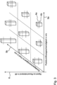
3 : ein Ausführungsbeispiel, welches erläutert, wie ein erster und ein zweiter Schwellwert für eine erste Diagnosekenngröße in Abhängigkeit einer ersten Messgröße und einer zweiten Messgröße ermittelt wird; und -
4 : ein Verfahren zum Betrieb eines Fluiddurchflussmessgeräts.
-
1 ,2 : various embodiments of a monitoring system with a fluid flow meter and a control device; -
3 : an embodiment which explains how a first and a second threshold value for a first diagnostic parameter is determined as a function of a first measured variable and a second measured variable; and -
4 : a method of operating a fluid flow meter.
Das Fluiddurchflussmessgerät 1 ist dazu ausgebildet, um eine erste Meldung zu erzeugen und an die Leiteinrichtung 50 zu übertragen. Die erste Meldung wird insbesondere dann erzeugt und an die Leiteinrichtung 50 übertragen, wenn zum Beispiel Diagnosewerte, wie die Genauigkeit, mit welcher das Fluiddurchflussmessgerät 1 den Durchfluss des Fluids 3 durch die Röhre 2 misst, nachlässt, insbesondere unterhalb eines ersten Schwellwerts 4a fällt.The fluid flow meter 1 is designed to generate a first message and transmit it to the
Die Leiteinrichtung 50 umfasst eine Ausgabeeinheit 51, insbesondere in Form eines Bildschirms. Auf dieser Ausgabeeinheit 51 kann die zumindest eine erste Meldung oder eine daraus abgeleitete Meldung visuell (und/oder akustisch) angezeigt werden. Ergänzend oder alternativ dazu kann die erste Meldung bzw. eine daraus abgeleitete Meldung über digitale Schnittstellen an eine angeschlossene Leiteinrichtung übertragen werden. Die Ausgabeeinheit 51 kann auch ein Webserver sein, der Daten bereithält, die von einem Computer, Tablett oder Smartphone aus aufgerufen werden können. An die Leiteinrichtung 50 kann ein Fluiddurchflussmessgerät 1 oder mehrere Fluiddurchflussmessgeräte 1 angeschlossen werden.The
Das Fluiddurchflussmessgerät 1 ist dazu ausgebildet, um eine erste Messgröße 5a, eine zweite Messgröße 5b und zumindest eine erste Diagnosekenngröße 6 (siehe
Das Fluiddurchflussmessgerät 1 umfasst weiterhin ein Diagnosesystem 7, welches dazu ausgebildet ist, um sowohl anhand der ersten Messgröße 5a als auch anhand der zumindest einen zweiten Messgröße 5b einen ersten Schwellwert 4a für die zumindest eine erste Diagnosekenngröße 6 zu ermitteln und um ab dessen erreichen eine erste Meldung an die übergeordnete Leiteinrichtung 50 auszugeben. Bei der ersten Meldung handelt es sich bevorzugt um eine Warnmeldung. Es kann sich allerdings auch um eine Störungsmeldung handeln. Das Diagnosesystem 7 ist bevorzugt außerdem dazu ausgebildet, um anhand der ersten Messgröße 5a und der zweiten Messgröße 5b einen zweiten Schwellwert 4b (
Das Fluiddurchflussmessgerät 1 umfasst weiterhin eine Messeinrichtung 8, die dazu ausgebildet ist, um die erste und die zumindest eine zweite Messgröße 5a, 5b zu erfassen. Der Signal-zu-Rauschabstand kann sich dabei auf die erste und/oder zweite Messgröße 5a, 5b beziehen.The fluid flow meter 1 further comprises a
Die Messeinrichtung 8 umfasst eine erste Sende- und Empfangseinheit 9a und eine zweite Sende- und Empfangseinheit 9b. Die erste Sende- und Empfangseinheit 9a ist dazu ausgebildet, um ein erstes Ultraschallsignal 10a zu erzeugen und auszusenden und um ein zweites Ultraschallsignal 10b zu empfangen. Die zweite Sende- und Empfangseinheit 9b ist dazu ausgebildet, um das zweite Ultraschallsignal 10b zu erzeugen und auszusenden und um das erste Ultraschallsignal 10a zu empfangen. Die erste und die zweite Sende- und Empfangseinheit 9a, 9b sind dabei sowohl in Umfangsrichtung als auch in Axialrichtung versetzt an der Röhre 2 angeordnet. Die Messeinrichtung 8 ist dazu ausgebildet, um beispielsweise die erste und die zweite Messgröße 5a, 5b über die erste und zweite Sende- und Empfangseinheit 9a, 9b zu ermitteln. Die erste und zweite Sende- und Empfangseinheit 9a, 9b sind natürlich dazu ausgebildet, um das erste und zweite Ultraschallsignal 10a, 10b durch das Fluid 3 hindurch auszusenden.The measuring
Die erste Sende- und Empfangseinheit 9a ist dazu ausgebildet, um das erste Ultraschallsignal 10a durch das Innere der Röhre 2 zur zweiten Sende- und Empfangseinheit 9b auszusenden, wobei die zweite Sende- und Empfangseinheit 9b dazu ausgebildet ist, um das erste Ultraschallsignal 10a zu empfangen und um das zweite Ultraschallsignal 10b durch das Innere der Röhre 2 zur ersten Sende- und Empfangseinheit 9a auszusenden. Die erste Sende- und Empfangseinheit 9a ist wiederum dazu ausgebildet, um das zweite Ultraschallsignal 10b zu empfangen. Insbesondere sind die erste und zweite Sende- und Empfangseinheit 9a ,9b derart zueinander angeordnet, dass innerhalb der Röhre 2 ein Sichtkontakt zwischen der ersten und zweiten Sende- und Empfangseinheit 9a, 9b vorliegt.The first transmitting and receiving
Die erste und/oder zweite Sende- und Empfangseinheit 9a ,9b können zumindest teilweise im Gehäuse des Fluiddurchflussmessgeräts 1 angeordnet sein. Die erste und/oder zweite Sende- und Empfangseinheit 9a, 9b können auch beabstandet zu dem Gehäuse des Fluiddurchflussmessgeräts 1 angeordnet und über eine entsprechende Datenverbindung (analog und/oder digital) mit dem Fluiddurchflussmessgerät 1 verbunden sein. Selbiges kann auch für den Drucksensor 11 und/oder den Temperatursensor 12 gelten.The first and/or second transmitting and receiving
In
Vorzugsweise umfasst die Messeinrichtung 8 noch einen Drucksensor 11, der dazu ausgebildet ist, um den Druck des Fluids 3 innerhalb der Röhre 2 zu messen. Ergänzend oder alternativ umfasst die Messeinrichtung 8 noch zumindest einen Temperatursensor 12, der dazu ausgebildet ist, um die Temperatur des Fluids 3 innerhalb der Röhre 2 zu messen.Preferably, the measuring
Weiter vorzugsweise umfasst das Diagnosesystem 7 noch eine Speichereinheit 13. In der Speichereinheit 13 ist eine Look-Up-Tabelle hinterlegt. Das Diagnosesystem 7 ist dazu ausgebildet, um in Abhängigkeit der zumindest einen ersten und zweiten Messgröße 5a, 5b den ersten Schwellwert 4a für die zumindest eine erste Diagnosekenngröße 6 aus der Look-Up-Tabelle auszulesen.The
In
Dargestellt ist, dass der erste Schwellwert 4a und der zweite Schwellwert 4b in Abhängigkeit von verschiedenen ersten und zweiten Messgrößen 5a, 5b unterschiedlich gewählt sind. Auch ein Abstand zwischen dem ersten Schwellwert 4a und dem zweiten Schwellwert 4b unterscheidet sich für verschiedene erste und zweite Messgrößen 5a, 5b.It is shown that the
Für den Fall, dass das Diagnosesystem 7 noch eine zweite Diagnosekenngröße erzeugt, kann ebenfalls eine entsprechende Look-Up-Tabelle verwendet werden, wobei die Arten für die erste Messgröße 5a und die zweite Messgröße 5b unterschiedlich gewählt sind.In the event that the
Die Erfindung ist nicht auf die beschriebenen Ausführungsbeispiele beschränkt. Im Rahmen der Erfindung sind alle beschriebenen und/oder gezeichneten Merkmale beliebig miteinander kombinierbar.The invention is not limited to the embodiments described. Within the scope of the invention, all described and/or drawn features can be combined with one another as desired.
BezugszeichenlisteList of reference symbols
- 11
- FluiddurchflussmessgerätFluid flow meter
- 22
- Röhretube
- 33
- FluidFluid
- 4a4a
- Erster SchwellwertFirst threshold
- 4b4b
- Zweiter SchwellwertSecond threshold
- 5a5a
- Erste MessgrößeFirst measurement
- 5b5b
- Zweite MessgrößeSecond measurement
- 66
- Erste DiagnosekenngrößeFirst diagnostic parameter
- 77
- DiagnosesystemDiagnostic system
- 88
- MesseinrichtungMeasuring device
- 9a9a
- Erste Sende- und EmpfangseinheitFirst transmitting and receiving unit
- 9b9b
- Zweite Sende- und EmpfangseinheitSecond transmitting and receiving unit
- 10a10a
- Erstes UltraschallsignalFirst ultrasound signal
- 10b10b
- Zweites UltraschallsignalSecond ultrasonic signal
- 1111
- DrucksensorPressure sensor
- 1212
- TemperatursensorTemperature sensor
- 1313
- SpeichereinheitStorage unit
- 1414
- KI-ModulAI module
- 5050
- LeiteinrichtungGuidance system
- 5151
- AusgabeeinheitOutput unit
- 100100
- ÜberwachungssystemMonitoring system
- S1, S2, S3S1, S2, S3
- VerfahrensschritteProcess steps
Claims (15)
Priority Applications (4)
| Application Number | Priority Date | Filing Date | Title |
|---|---|---|---|
| DE102023106668.4A DE102023106668A1 (en) | 2023-03-16 | 2023-03-16 | Fluid flow meter, monitoring system with at least one such fluid flow meter and method for operating a fluid flow meter |
| EP24161658.0A EP4439020A1 (en) | 2023-03-16 | 2024-03-06 | Fluid flow meter, monitoring system having at least one such fluid flow meter and method for operating a fluid flow meter |
| US18/605,025 US20240310201A1 (en) | 2023-03-16 | 2024-03-14 | Fluid flow meter, monitoring system comprising at least one such fluid flow meter and method for operating a fluid flow meter |
| CN202410301172.6A CN118670483A (en) | 2023-03-16 | 2024-03-15 | Fluid flow meter, monitoring system comprising at least one such fluid flow meter and method for operating a fluid flow meter |
Applications Claiming Priority (1)
| Application Number | Priority Date | Filing Date | Title |
|---|---|---|---|
| DE102023106668.4A DE102023106668A1 (en) | 2023-03-16 | 2023-03-16 | Fluid flow meter, monitoring system with at least one such fluid flow meter and method for operating a fluid flow meter |
Publications (1)
| Publication Number | Publication Date |
|---|---|
| DE102023106668A1 true DE102023106668A1 (en) | 2024-09-19 |
Family
ID=90362196
Family Applications (1)
| Application Number | Title | Priority Date | Filing Date |
|---|---|---|---|
| DE102023106668.4A Pending DE102023106668A1 (en) | 2023-03-16 | 2023-03-16 | Fluid flow meter, monitoring system with at least one such fluid flow meter and method for operating a fluid flow meter |
Country Status (4)
| Country | Link |
|---|---|
| US (1) | US20240310201A1 (en) |
| EP (1) | EP4439020A1 (en) |
| CN (1) | CN118670483A (en) |
| DE (1) | DE102023106668A1 (en) |
Citations (8)
| Publication number | Priority date | Publication date | Assignee | Title |
|---|---|---|---|---|
| US20110277558A1 (en) * | 2010-05-12 | 2011-11-17 | Sick Engineering Gmbh | Ultrasound measurement of the flow speed of a fluid in a conduit |
| DE102012104042A1 (en) * | 2012-05-09 | 2013-11-14 | Endress + Hauser Flowtec Ag | Method for monitoring the operating state of an ultrasonic transducer in an ultrasonic flowmeter |
| US20150292926A1 (en) * | 2012-11-05 | 2015-10-15 | Panasonic Intellectual Property Management Co., Ltd. | Flow meter device and flow rate calculation method thereof |
| DE102017213084A1 (en) * | 2017-07-28 | 2019-01-31 | Siemens Aktiengesellschaft | Method and device for safe flow measurement |
| WO2020112731A1 (en) * | 2018-11-26 | 2020-06-04 | Daniel Measurement And Control, Inc. | Flow metering system condition-based monitoring and failure to predictive mode |
| DE102018133316A1 (en) * | 2018-12-21 | 2020-06-25 | Endress+Hauser Flowtec Ag | Process for operating a field device of automation technology and field device of automation technology |
| DE202020003345U1 (en) * | 2020-02-28 | 2020-08-18 | Diehl Metering Gmbh | Ultrasonic flow meter with signal quality monitoring |
| DE102020002837A1 (en) * | 2020-05-12 | 2021-11-18 | Diehl Metering Gmbh | Method for operating a measuring device and measuring device |
Family Cites Families (8)
| Publication number | Priority date | Publication date | Assignee | Title |
|---|---|---|---|---|
| US8170812B2 (en) * | 2007-10-16 | 2012-05-01 | Daniel Measurement And Control, Inc. | Method and system for detecting deposit buildup within an ultrasonic flow meter |
| JP5323928B2 (en) * | 2008-05-01 | 2013-10-23 | マイクロ モーション インコーポレイテッド | How to diagnose from abnormal flowmeter parameters |
| EP2601489A1 (en) * | 2010-08-02 | 2013-06-12 | Siemens Aktiengesellschaft | Coriolis mass flowmeter and method for operating a coriolis mass flowmeter |
| US20140111342A1 (en) * | 2012-10-19 | 2014-04-24 | Daniel Measurement And Control, Inc. | Condition monitoring with alarm confidence levels for flow metering systems |
| US20170082480A1 (en) * | 2015-09-21 | 2017-03-23 | Honeywell International Inc. | Real-time condition based monitoring (cbm) based ultrasonic meter (usm) accuracy performance detection and notification |
| US11215493B2 (en) * | 2018-08-02 | 2022-01-04 | Ge Infrastructure Sensing, Llc | Flowmeter as an asset |
| CN115371750A (en) * | 2022-08-31 | 2022-11-22 | 浙江威星智能仪表股份有限公司 | Gas ultrasonic flowmeter self-diagnosis method based on sound velocity comparison |
| US20250198816A1 (en) * | 2023-12-18 | 2025-06-19 | Sensia Netherlands B.V. | Systems and methods of high accuracy flow measurements |
-
2023
- 2023-03-16 DE DE102023106668.4A patent/DE102023106668A1/en active Pending
-
2024
- 2024-03-06 EP EP24161658.0A patent/EP4439020A1/en not_active Withdrawn
- 2024-03-14 US US18/605,025 patent/US20240310201A1/en active Pending
- 2024-03-15 CN CN202410301172.6A patent/CN118670483A/en active Pending
Patent Citations (8)
| Publication number | Priority date | Publication date | Assignee | Title |
|---|---|---|---|---|
| US20110277558A1 (en) * | 2010-05-12 | 2011-11-17 | Sick Engineering Gmbh | Ultrasound measurement of the flow speed of a fluid in a conduit |
| DE102012104042A1 (en) * | 2012-05-09 | 2013-11-14 | Endress + Hauser Flowtec Ag | Method for monitoring the operating state of an ultrasonic transducer in an ultrasonic flowmeter |
| US20150292926A1 (en) * | 2012-11-05 | 2015-10-15 | Panasonic Intellectual Property Management Co., Ltd. | Flow meter device and flow rate calculation method thereof |
| DE102017213084A1 (en) * | 2017-07-28 | 2019-01-31 | Siemens Aktiengesellschaft | Method and device for safe flow measurement |
| WO2020112731A1 (en) * | 2018-11-26 | 2020-06-04 | Daniel Measurement And Control, Inc. | Flow metering system condition-based monitoring and failure to predictive mode |
| DE102018133316A1 (en) * | 2018-12-21 | 2020-06-25 | Endress+Hauser Flowtec Ag | Process for operating a field device of automation technology and field device of automation technology |
| DE202020003345U1 (en) * | 2020-02-28 | 2020-08-18 | Diehl Metering Gmbh | Ultrasonic flow meter with signal quality monitoring |
| DE102020002837A1 (en) * | 2020-05-12 | 2021-11-18 | Diehl Metering Gmbh | Method for operating a measuring device and measuring device |
Also Published As
| Publication number | Publication date |
|---|---|
| US20240310201A1 (en) | 2024-09-19 |
| CN118670483A (en) | 2024-09-20 |
| EP4439020A1 (en) | 2024-10-02 |
Similar Documents
| Publication | Publication Date | Title |
|---|---|---|
| DE60029196T2 (en) | FLOW MEASUREMENT WITH DIAGNOSTIC MEANS | |
| DE102007036057B4 (en) | Method for evaluating the performance of a control valve and associated device | |
| EP3234512B1 (en) | Differential pressure type flowmeter | |
| EP2513612A1 (en) | Method for operating a coriolis mass flow rate meter and coriolis mass flow rate meter | |
| DE102007043328A1 (en) | Method for monitoring a process plant with a fieldbus of process automation technology | |
| EP3222980B1 (en) | Flow meter with error detection | |
| DE2012961A1 (en) | Method and device for checking the accuracy of a flow measuring device in operation | |
| DE102016201933A1 (en) | Measuring arrangement for monitoring the bunkering of a large ship | |
| EP3995790A2 (en) | Flowmeter, method for operating a flowmeter, installation and method for operating an installation | |
| DE102016113200B4 (en) | Method of operating a flow meter and flow meter | |
| WO2023285904A1 (en) | Method for determining a flow rate, flow sensor, and measuring system comprising a flow sensor | |
| DE102013200685A1 (en) | Process instrumentation field device i.e. Coriolis mass flow measuring device, for monitoring interior of housing, has evaluation device monitoring resistance signal and outputting signal for indicating error condition | |
| DE102023106668A1 (en) | Fluid flow meter, monitoring system with at least one such fluid flow meter and method for operating a fluid flow meter | |
| EP4042111A1 (en) | Method for monitoring a measuring device system | |
| DE202023101324U1 (en) | Fluid flow meter and monitoring system with at least one such fluid flow meter | |
| DE102014101647B4 (en) | Method for calibrating a measuring system and calibration device | |
| DE2821711A1 (en) | METHOD AND DEVICE FOR CHECKING A FLOW METER | |
| WO2019042642A1 (en) | DIFFERENTIAL PRESSURE MEASURING DEVICE | |
| EP3084359A1 (en) | Method and measuring assembly according to the differential pressure principle having a zero-point calibration | |
| WO2021058207A1 (en) | Arrangement and method for identifying and correcting a faulty volumetric flow measurement | |
| WO2020249163A1 (en) | Coriolis flow meter which compensates for viscosity-related measurement errors | |
| EP3114439A1 (en) | Method for checking a measuring device | |
| WO2023117260A1 (en) | Detecting foreign bodies in flowing measured media | |
| EP1743226A2 (en) | Method for determining service intervals for field devices of automation systems | |
| EP3555714A1 (en) | Method for the application-specific setting of a field device |
Legal Events
| Date | Code | Title | Description |
|---|---|---|---|
| R012 | Request for examination validly filed | ||
| R016 | Response to examination communication | ||
| R081 | Change of applicant/patentee |
Owner name: ENDRESS+HAUSER SICK GMBH+CO. KG, DE Free format text: FORMER OWNER: SICK ENGINEERING GMBH, 01458 OTTENDORF-OKRILLA, DE |
|
| R082 | Change of representative |
Representative=s name: MANITZ FINSTERWALD PATENT- UND RECHTSANWALTSPA, DE |
|
| R082 | Change of representative |
Representative=s name: MANITZ FINSTERWALD PATENT- UND RECHTSANWALTSPA, DE |