DE102023104889A1 - Portable container holder for use in a bioprocess - Google Patents

Portable container holder for use in a bioprocess Download PDF

Info

Publication number
DE102023104889A1
DE102023104889A1 DE102023104889.9A DE102023104889A DE102023104889A1 DE 102023104889 A1 DE102023104889 A1 DE 102023104889A1 DE 102023104889 A DE102023104889 A DE 102023104889A DE 102023104889 A1 DE102023104889 A1 DE 102023104889A1
Authority
DE
Germany
Prior art keywords
magnet
drive
mixing element
container
container holder
Prior art date
Legal status (The legal status is an assumption and is not a legal conclusion. Google has not performed a legal analysis and makes no representation as to the accuracy of the status listed.)
Pending
Application number
DE102023104889.9A
Other languages
German (de)
Inventor
Marc Hogreve
Current Assignee (The listed assignees may be inaccurate. Google has not performed a legal analysis and makes no representation or warranty as to the accuracy of the list.)
Sartorius Stedim Biotech GmbH
Original Assignee
Sartorius Stedim Biotech GmbH
Priority date (The priority date is an assumption and is not a legal conclusion. Google has not performed a legal analysis and makes no representation as to the accuracy of the date listed.)
Filing date
Publication date
Application filed by Sartorius Stedim Biotech GmbH filed Critical Sartorius Stedim Biotech GmbH
Priority to DE102023104889.9A priority Critical patent/DE102023104889A1/en
Priority to PCT/EP2024/053741 priority patent/WO2024179843A1/en
Priority to EP24705454.7A priority patent/EP4673252A1/en
Publication of DE102023104889A1 publication Critical patent/DE102023104889A1/en
Pending legal-status Critical Current

Links

Images

Classifications

    • BPERFORMING OPERATIONS; TRANSPORTING
    • B01PHYSICAL OR CHEMICAL PROCESSES OR APPARATUS IN GENERAL
    • B01FMIXING, e.g. DISSOLVING, EMULSIFYING OR DISPERSING
    • B01F33/00Other mixers; Mixing plants; Combinations of mixers
    • B01F33/45Magnetic mixers; Mixers with magnetically driven stirrers
    • B01F33/453Magnetic mixers; Mixers with magnetically driven stirrers using supported or suspended stirring elements
    • BPERFORMING OPERATIONS; TRANSPORTING
    • B01PHYSICAL OR CHEMICAL PROCESSES OR APPARATUS IN GENERAL
    • B01FMIXING, e.g. DISSOLVING, EMULSIFYING OR DISPERSING
    • B01F33/00Other mixers; Mixing plants; Combinations of mixers
    • B01F33/50Movable or transportable mixing devices or plants
    • B01F33/502Vehicle-mounted mixing devices
    • B01F33/5024Vehicle-mounted mixing devices the vehicle being moved by human force
    • BPERFORMING OPERATIONS; TRANSPORTING
    • B01PHYSICAL OR CHEMICAL PROCESSES OR APPARATUS IN GENERAL
    • B01FMIXING, e.g. DISSOLVING, EMULSIFYING OR DISPERSING
    • B01F35/00Accessories for mixers; Auxiliary operations or auxiliary devices; Parts or details of general application
    • B01F35/40Mounting or supporting mixing devices or receptacles; Clamping or holding arrangements therefor
    • B01F35/42Clamping or holding arrangements for mounting receptacles on mixing devices
    • B01F35/421Clamping or holding arrangements for mounting receptacles on mixing devices having a cup-shaped or cage-type form
    • BPERFORMING OPERATIONS; TRANSPORTING
    • B01PHYSICAL OR CHEMICAL PROCESSES OR APPARATUS IN GENERAL
    • B01FMIXING, e.g. DISSOLVING, EMULSIFYING OR DISPERSING
    • B01F35/00Accessories for mixers; Auxiliary operations or auxiliary devices; Parts or details of general application
    • B01F35/40Mounting or supporting mixing devices or receptacles; Clamping or holding arrangements therefor
    • B01F35/43Supporting receptacles on frames or stands
    • BPERFORMING OPERATIONS; TRANSPORTING
    • B01PHYSICAL OR CHEMICAL PROCESSES OR APPARATUS IN GENERAL
    • B01FMIXING, e.g. DISSOLVING, EMULSIFYING OR DISPERSING
    • B01F35/00Accessories for mixers; Auxiliary operations or auxiliary devices; Parts or details of general application
    • B01F35/50Mixing receptacles
    • B01F35/513Flexible receptacles, e.g. bags supported by rigid containers

Landscapes

  • Chemical & Material Sciences (AREA)
  • Chemical Kinetics & Catalysis (AREA)
  • Details Of Rigid Or Semi-Rigid Containers (AREA)
  • Mixers With Rotating Receptacles And Mixers With Vibration Mechanisms (AREA)

Abstract

Die Erfindung betrifft eine portable Behälterhalterung zur Verwendung in einem Bioprozess zum Halten und Transportieren eines mit einem Fluid (2) gefüllten Einwegbehälters (3), der ein magnetangetriebenes Mischelement (4) zum Durchmischen des Fluids (2) aufgenommen hat, wobei die portable Behälterhalterung (1) eine Behälteraufnahme (7) zur Aufnahme des Einwegbehälters (3) mit einer Antriebsstelle (8) aufweist, an welcher das Mischelement (4) im in der Behälteraufnahme (7) aufgenommenen Einwegbehälter (3) derart anordenbar ist, dass das Mischelement (4) durch eine Antriebseinheit (9) an der Antriebsstelle (8) antreibbar ist. Es wird vorgeschlagen, dass die portable Behälterhalterung (1) eine Transportsicherung (11) zum Sichern und Entsichern des an der Antriebsstelle (8) angeordneten Mischelements (4) in seiner Position aufweist und dass die Transportsicherung (11) einen Magneten (10) aufweist, welcher zwischen einer definierten Sicherungsposition (12), in der das Mischelement (4) positionsgesichert ist, und einer definierten Entsicherungsposition (13), in der das Mischelement (4) positionsentsichert ist, bewegbar ist.

Figure DE102023104889A1_0000
The invention relates to a portable container holder for use in a bioprocess for holding and transporting a disposable container (3) filled with a fluid (2), which has received a magnetically driven mixing element (4) for mixing the fluid (2), wherein the portable container holder (1) has a container receptacle (7) for receiving the disposable container (3) with a drive point (8) at which the mixing element (4) can be arranged in the disposable container (3) received in the container receptacle (7) in such a way that the mixing element (4) can be driven by a drive unit (9) at the drive point (8). It is proposed that the portable container holder (1) has a transport lock (11) for securing and unlocking the mixing element (4) arranged at the drive point (8) in its position and that the transport lock (11) has a magnet (10) which is movable between a defined securing position (12), in which the mixing element (4) is secured in position, and a defined unlocking position (13), in which the mixing element (4) is unlocked in position.
Figure DE102023104889A1_0000

Description

Die vorliegende Erfindung betrifft eine portable Behälterhalterung zur Verwendung in einem Bioprozess zum Halten und Transportieren eines mit einem Fluid gefüllten Einwegbehälters gemäß dem Oberbegriff von Anspruch 1, ein System zur Verwendung in einem Bioprozess gemäß dem Oberbegriff von Anspruch 8 sowie ein Verfahren zum Halten und Transportieren eines Einwegbehälters gemäß dem Oberbegriff von Anspruch 11.The present invention relates to a portable container holder for use in a bioprocess for holding and transporting a disposable container filled with a fluid according to the preamble of claim 1, a system for use in a bioprocess according to the preamble of claim 8 and a method for holding and transporting a disposable container according to the preamble of claim 11.

Portable Behälterhalterungen zum Halten und Transportieren von Einwegbehältern kommen in verschieden Ausführungen in unterschiedlichen Bereichen der Biotechnologie zum Einsatz. Um etwa ein bestimmtes Fluid, wie beispielsweise ein einen aufgereinigten pharmazeutischen Inhaltsstoff beinhaltendes Fluid oder ein Kultivierungsmedium, lagern, transportieren oder verarbeiten zu können, wird das Fluid zunächst in einen, insbesondere flexiblen, Einwegbehälter gefüllt. Während der Einwegbehälter als solcher nur aufwändig transportierbar und nur schwer zu halten wäre, insbesondere aufgrund des überaus hohen Gewichtes des aufgenommenen Fluids, wird der Einwegbehälter, in der Regel vor Befüllung mit dem Fluid, in einer portablen Behälterhalterung angeordnet. Insbesondere für den häufigen Fall, dass die Einwegbehälter große Mengen an Fluid fassen, kann durch die portable Behälterhalterung das Halten und Transportieren des Einwegbehälters ermöglicht werden. Die portable Behälterhalterung lässt sich zum Transport beispielsweise anheben, etwa mittels eines Hubwagens, und bewegen oder direkt verschieben, etwa über Transportrollen oder Schienen.Portable container holders for holding and transporting disposable containers are used in various designs in different areas of biotechnology. In order to be able to store, transport or process a certain fluid, such as a fluid containing a purified pharmaceutical ingredient or a cultivation medium, the fluid is first filled into a disposable container, in particular a flexible one. While the disposable container as such would be difficult to transport and hold, in particular due to the extremely high weight of the fluid held, the disposable container is usually placed in a portable container holder before being filled with the fluid. In particular, in the frequent case that the disposable container holds large quantities of fluid, the portable container holder can make it possible to hold and transport the disposable container. The portable container holder can be lifted for transport, for example using a pallet truck, and moved or moved directly, for example using transport rollers or rails.

Eine Behälterhalterung zum Halten und Transportieren eines mit Fluid gefüllten Einwegbehälters weist zunächst eine Behälteraufnahme auf. In der Behälteraufnahme ist ein Einwegbehälter aufnehmbar, welcher korrespondierend zu der Behälteraufnahme ausgebildet sein kann.A container holder for holding and transporting a disposable container filled with fluid initially has a container receptacle. A disposable container can be accommodated in the container receptacle, which can be designed to correspond to the container receptacle.

Da während des Haltens des mit Fluid gefüllten Einwegbehälters häufig vorgesehen ist, dass das Fluid innerhalb des Einwegbehälters auch durchmischt wird, nimmt der Einwegbehälter ein Mischelement, wie etwa einen Rührer, insbesondere einen Impeller, auf. Das Mischelement ist magnetangetrieben, so dass das Mischelement berührungslos angetrieben und das Fluid bedarfsweise innerhalb des Einwegbehälters durchmischt werden kann.Since it is often intended that the fluid within the disposable container is also mixed while the disposable container is being held, the disposable container accommodates a mixing element, such as a stirrer, in particular an impeller. The mixing element is magnetically driven, so that the mixing element can be driven without contact and the fluid can be mixed within the disposable container as required.

Die Behälteraufnahme weist eine Antriebsstelle auf, über welche das Mischelement durch eine Antriebseinheit magnetisch antreibbar ist. Die Antriebseinheit kann dabei etwa eine externe Antriebseinheit sein, welche ebenfalls an oder in der Nähe der Antriebsstelle anordenbar ist. Das Mischelement im Einwegbehälter wird an der Antriebsstelle angeordnet, wenn der Einwegbehälter in der Behälteraufnahme aufgenommen wird. Das Antreiben des Mischelements über die Antriebsstelle durch die Antriebseinheit erfolgt sodann beispielsweise berührungslos über ein von der Antriebseinheit erzeugtes Magnetfeld, welches das Mischelement innerhalb des Einwegbehälters in Rotation versetzt.The container holder has a drive point via which the mixing element can be magnetically driven by a drive unit. The drive unit can be an external drive unit, for example, which can also be arranged at or near the drive point. The mixing element in the disposable container is arranged at the drive point when the disposable container is received in the container holder. The driving of the mixing element via the drive point by the drive unit then takes place, for example, contactlessly via a magnetic field generated by the drive unit, which causes the mixing element to rotate within the disposable container.

Der bekannte Stand der Technik ( WO 2017/129203 A1 ) von dem die Erfindung ausgeht, betrifft eine portable Behälterhalterung, die das Halten und Transportieren eines mit Fluid gefüllten Einwegbehälters ermöglicht, wobei hier während des Haltens das Fluid über ein von dem Einwegbehälter aufgenommenes Mischelement mischbar ist. Die Behälterhalterung weist eine Behälteraufnahme auf, in welcher der Einwegbehälter aufnehmbar ist. Die Behälteraufnahme weist eine Antriebsstelle auf, an welcher das Mischelement anordenbar ist, so dass das Mischelement durch eine externe Antriebseinheit an der Antriebsstelle angetrieben werden kann.The known state of the art ( WO 2017/129203 A1 ) from which the invention is based, relates to a portable container holder which enables the holding and transport of a disposable container filled with fluid, wherein the fluid can be mixed while being held via a mixing element accommodated by the disposable container. The container holder has a container receptacle in which the disposable container can be accommodated. The container receptacle has a drive point at which the mixing element can be arranged, so that the mixing element can be driven by an external drive unit at the drive point.

Obschon sich derartige portable Behälterhalterungen aus dem Stand der Technik zum Halten und Transportieren eines mit Fluid gefüllten Einwegbehälters überaus bewährt haben und mit diesen während des Haltens das Fluid auch zuverlässig durchmischt werden kann, so ergibt sich doch der Nachteil, dass das magnetangetriebene Mischelement, insbesondere während des Transports, verrutschen kann. Zwar ist in der Regel eine Art Lagerdorn vorgesehen, auf welchem das Mischelement zunächst drehbar angeordnet ist, jedoch kann das Mischelement von diesem Lagerdorn herunterrutschen und sich daraufhin frei innerhalb des Einwegbehälters bewegen. Aus diesem Grund kann es, beispielsweise bei Erschütterungen oder Bewegungen des Fluids, leicht dazu kommen, dass das Mischelement, welches zunächst an der Antriebsstelle, insbesondere auf dem Lagerdorn, angeordnet worden ist, innerhalb des Einwegbehälters verrutscht und daraufhin nicht mehr an der Antriebsstelle angeordnet ist. Folglich ist das verrutschte Mischelement auch nicht mehr antreibbar und damit das Fluid nicht mehr durchmischbar.Although such portable container holders from the prior art have proven to be extremely effective for holding and transporting a disposable container filled with fluid and can also be used to reliably mix the fluid while it is being held, there is the disadvantage that the magnetically driven mixing element can slip, particularly during transport. Although a type of bearing mandrel is usually provided on which the mixing element is initially arranged so that it can rotate, the mixing element can slip off this bearing mandrel and then move freely within the disposable container. For this reason, for example in the event of vibrations or movements of the fluid, it can easily happen that the mixing element, which was initially arranged at the drive point, in particular on the bearing mandrel, slips within the disposable container and is then no longer arranged at the drive point. Consequently, the slipped mixing element can no longer be driven and thus the fluid can no longer be mixed.

Zwar sind aus dem Stand der Technik grundsätzlich Lösungen bekannt, wie etwa eine magnetische Kappe aus der US 2005/0002274 A1 , welche das vorstehend genannte Problem vermeiden sollen, jedoch sind diese Lösungen, insbesondere hinsichtlich deren Handhabbarkeit, derzeit nicht ausgereift. So ist es etwa bei einer aufschraubbaren oder ansteckbaren Kappe regelmäßig der Fall, dass diese verloren geht, bei Bedarf nicht auffindbar ist oder nur schlecht montierbar sowie demontierbar ist.Although solutions are known from the state of the art, such as a magnetic cap from the US 2005/0002274 A1 which are intended to avoid the problem mentioned above, but these solutions are not yet fully developed, particularly in terms of their handling. For example, it is often the case that a screw-on or clip-on cap gets lost, cannot be found when needed, or is difficult to assemble or disassemble.

Der Erfindung liegt das Problem zugrunde, die bekannte portable Behälterhalterung hinsichtlich des Haltens und des Transports eines Einwegbehälters, der ein Mischelement aufgenommen hat, zu optimieren, insbesondere dahingehend zu optimieren, dass das Mischelement, insbesondere auch während des Transports, zuverlässig in Position gehalten werden kann.The invention is based on the problem of optimizing the known portable container holder with regard to holding and transporting a disposable container which has received a mixing element, in particular to optimize it so that the mixing element can be reliably held in position, in particular also during transport.

Das obige Problem wird durch die Merkmale des kennzeichnenden Teils von Anspruch 1 gelöst.The above problem is solved by the features of the characterizing part of claim 1.

Wesentlich ist die grundsätzliche Überlegung, dass die portable Behälterhalterung eine Transportsicherung aufweist. Über die Transportsicherung lässt sich das Mischelement sowohl während des Haltens des Einwegbehälters als auch während des Transports des Einwegbehälters zuverlässig in Position halten. Hierbei wird das magnetangetriebene und damit auch magnetische Mischelement durch einen Magneten der Transportsicherung positionsgesichert, wenn der Magnet in eine definierte Sicherungsposition bewegt wird. In der Sicherungsposition wirkt das Magnetfeld des Magneten auf das Mischelement und hält dieses entsprechend in Position innerhalb des Einwegbehälters. Sobald das Mischelement positionsentsichert werden soll, ist der Magnet in eine definierte Entsicherungsposition bewegbar, in welcher das Magnetfeld des Magneten das Mischelement nicht mehr positionssichert. Dies kann etwa der Fall sein, wenn das Mischelement über eine externe Antriebseinheit angetrieben und das Fluid durchmischt werden soll. Das positionsentsicherte Mischelement ist insbesondere durch die Antriebseinheit antreibbar, so dass das Mischelement rotiert. The basic consideration is that the portable container holder has a transport lock. The transport lock can be used to reliably hold the mixing element in position both while the disposable container is being held and during transport. The magnet-driven and therefore magnetic mixing element is secured in position by a magnet in the transport lock when the magnet is moved to a defined securing position. In the securing position, the magnetic field of the magnet acts on the mixing element and holds it in position within the disposable container. As soon as the mixing element is to be released, the magnet can be moved to a defined release position in which the magnetic field of the magnet no longer secures the mixing element. This can be the case, for example, if the mixing element is driven by an external drive unit and the fluid is to be mixed. The position-released mixing element can be driven in particular by the drive unit so that the mixing element rotates.

Hierdurch kann das Fluid entsprechend innerhalb des Einwegbehälters durchmischt werden.This allows the fluid to be mixed accordingly within the disposable container.

Im Einzelnen wird vorgeschlagen, dass die portable Behälterhalterung eine Transportsicherung zum Sichern und Entsichern des an der Antriebsstelle angeordneten Mischelements in seiner Position aufweist, und, dass die Transportsicherung einen Magneten aufweist, welcher zwischen einer definierten Sicherungsposition, in der das Mischelement positionsgesichert ist, und einer definierten Entsicherungsposition, in der das Mischelement positionsentsichert ist, bewegbar ist.In detail, it is proposed that the portable container holder has a transport lock for securing and unlocking the mixing element arranged at the drive point in its position, and that the transport lock has a magnet which is movable between a defined securing position in which the mixing element is secured in position and a defined unlocking position in which the mixing element is unlocked in position.

Nach einer vorteilhaften Ausgestaltung gemäß Anspruch 2 weist die Transportsicherung eine Magnethalterung auf. Durch die Magnethalterung lässt sich der Magnet auf konstruktiv einfache Art und Weise sowohl halten als auch bewegen. Die Magnethalterung kann eine Magnetführung aufweisen, welche eine geführte, also definierte, Bewegung des Magneten ermöglicht. Eine Führungsbefestigung der Magnethalterung stellt eine konstruktive Möglichkeit dar die Magnetführung an der Behälteraufnahme starr zu befestigen.According to an advantageous embodiment according to claim 2, the transport lock has a magnetic holder. The magnetic holder allows the magnet to be both held and moved in a structurally simple manner. The magnetic holder can have a magnetic guide, which enables a guided, i.e. defined, movement of the magnet. A guide fastening of the magnetic holder represents a structural possibility for rigidly fastening the magnetic guide to the container holder.

In Anspruch 3 wird vorteilhafterweise eine Bedienanordnung der Transportsicherung spezifiziert. Über die Bedienanordnung ist die Transportsicherung bedienbar, so dass der Magnet bedarfsweise in die Entsicherungsposition oder Sicherungsposition bewegt werden kann. Ein Bedienelement der Bedienanordnung kann eine komfortable manuelle, insbesondere händische, Betätigung der Bedienanordnung ermöglichen. Über eine Arretieranordnung lässt sich der Magnet zuverlässig in der Sicherungsposition oder der Entsicherungsposition arretieren, so dass dieser nicht unbeabsichtigt bewegbar ist. Eine Vorspannanordnung kann den Magneten vorspannen, um diesen automatisch über die Vorspannung in die Sicherungsposition oder Entsicherungsposition zu bewegen. Hierdurch lässt sich zum einen der Bedienkomfort erhöhen und zum anderen können Benutzerfehler vermieden werden, indem sichergestellt wird, dass der Magnet in die entsprechende Position bewegt wird.Claim 3 advantageously specifies an operating arrangement for the transport lock. The transport lock can be operated via the operating arrangement so that the magnet can be moved into the unlocking position or the securing position as required. An operating element of the operating arrangement can enable convenient manual, in particular hand-operated, operation of the operating arrangement. The magnet can be reliably locked in the securing position or the unlocking position via a locking arrangement so that it cannot be moved unintentionally. A pre-tensioning arrangement can pre-tension the magnet in order to automatically move it into the securing position or the unlocking position via the pre-tension. This increases ease of use on the one hand and prevents user errors on the other by ensuring that the magnet is moved into the appropriate position.

Anspruch 4 spezifiziert vorteilhafte Ausgestaltungen den Magneten der Transportsicherung betreffend. Die Ausgestaltung des Magneten als Dauermagnet stellt eine günstige und verhältnismäßig wenig aufwendige Ausgestaltung des Magneten dar. Gegenüber etwa einer Ausgestaltung des Magneten als Elektromagnet ergibt sich zudem der Vorteil, dass der als Dauermagnet ausgebildete Magnet unabhängig von etwaigen Stromquellen ist und damit die Betriebssicherheit der Transportsicherung, insbesondere während des Transports, erhöht werden kann. Eine Magnetausnehmung des Magneten kann eine Anordnung des Magneten um das Mischelement herum ermöglichen, wodurch eine zuverlässige Positionssicherung erreicht wird. Die Magnetausnehmung kann zudem den Benutzungskomfort der Transportsicherung erhöhen, indem diese als Positionierhilfe ausgebildet ist.Claim 4 specifies advantageous embodiments relating to the magnet of the transport lock. The design of the magnet as a permanent magnet represents a favorable and relatively inexpensive design of the magnet. Compared to a design of the magnet as an electromagnet, for example, there is also the advantage that the magnet designed as a permanent magnet is independent of any power sources and thus the operational reliability of the transport lock can be increased, especially during transport. A magnet recess in the magnet can enable the magnet to be arranged around the mixing element, thereby achieving reliable positional security. The magnet recess can also increase the user comfort of the transport lock by designing it as a positioning aid.

Nach einer weiteren vorteilhaften Ausgestaltung gemäß Anspruch 5 weist die Behälteraufnahme eine oder mehrere Behälterwände und einen Behälterboden auf, an welchem die Antriebsstelle angeordnet ist. Hierdurch lässt sich eine konstruktiv einfache Behälteraufnahme schaffen. Die Antriebsstelle kann eine Antriebsausnehmung aufweisen, wodurch ein zuverlässiges Antreiben des Mischelements durch die Antriebseinheit sichergestellt wird.According to a further advantageous embodiment according to claim 5, the container holder has one or more container walls and a container base on which the drive point is arranged. This makes it possible to create a structurally simple container holder. The drive point can have a drive recess, which ensures that the mixing element is reliably driven by the drive unit.

In Anspruch 6 werden vorteilhafte Anordnungen des Magneten vorgeschlagen, welche eine zuverlässige Positionssicherung des Mischelements ermöglichen.In claim 6, advantageous arrangements of the magnet are proposed, which enable a reliable position securing of the mixing element.

Anspruch 7 bildet die konstruktive Ausgestaltung der portablen Behälterhalterung vorteilhaft weiter. Eine Antriebsaufnahme bietet eine konstruktiv günstige Art und Weise eine externe Antriebseinheit betriebsbereit aufzunehmen. Transportrollen stellen die Portabilität der Behälterhalterung sicher, wobei diese insbesondere ermöglichen, dass die portable Behälterhalterung ohne weitere Hilfsmittel, wie einen Hubwagen oder dergleichen, durch einen Benutzer ohne übermäßigen Kraftaufwand bewegbar ist.Claim 7 advantageously develops the structural design of the portable container holder. A drive mount offers a structurally favorable way of accommodating an external drive unit ready for operation. Transport rollers ensure the portability of the container holder, whereby these in particular enable the portable container holder to be moved by a user without additional aids, such as a lifting truck or the like, without excessive effort.

Nach einer weiteren Lehre gemäß Anspruch 8, der eigenständige Bedeutung zukommt, wird ein System zur Verwendung in einem Bioprozess beansprucht. Das System weist eine portable Behälterhalterung mit einer Behälteraufnahme und einen Einwegbehälter, der ein magnetangetriebenes Mischelement zum Durchmischen eines Fluids aufgenommen hat, auf, wobei der Einwegbehälter in der Behälteraufnahme aufgenommen ist, die Behälteraufnahme eine Antriebsstelle aufweist und das Mischelement im in der Behälteraufnahme aufgenommenen Einwegbehälter derart an der Antriebsstelle der Behälteraufnahme angeordnet ist, dass das Mischelement durch eine Antriebseinheit, insbesondere magnetisch, antreibbar ist.According to a further teaching according to claim 8, which has independent significance, a system for use in a bioprocess is claimed. The system has a portable container holder with a container receptacle and a disposable container which has received a magnetically driven mixing element for mixing a fluid, wherein the disposable container is received in the container receptacle, the container receptacle has a drive point and the mixing element in the disposable container received in the container receptacle is arranged at the drive point of the container receptacle in such a way that the mixing element can be driven by a drive unit, in particular magnetically.

Wesentlich bei dem vorschlagsgemäßen System ist, dass die portable Behälterhalterung eine Transportsicherung zum Sichern und Entsichern des an der Antriebsstelle angeordneten Mischelements in seiner Position aufweist, wobei die Transportsicherung einen Magneten aufweist, welcher zwischen einer definierten Sicherungsposition, in der das Mischelement positionsgesichert ist, und einer definierten Entsicherungsposition, in der das Mischelement positionsentsichert ist, bewegbar ist.What is essential in the proposed system is that the portable container holder has a transport lock for securing and unlocking the mixing element arranged at the drive point in its position, wherein the transport lock has a magnet which is movable between a defined securing position in which the mixing element is secured in position and a defined unlocking position in which the mixing element is unlocked in position.

Auf alle Ausführungen zu der vorschlagsgemäßen portablen Behälterhalterung darf verwiesen werden.Reference may be made to all statements regarding the proposed portable container holder.

Anspruch 9 betrifft vorteilhafte Ausgestaltungen des Einwegbehälters und des davon aufgenommenen Mischelements. Ein flexibler Einwegbehälter kann insbesondere im nicht gefüllten Zustand Vorteile beim Transport und der Lagerung sowie der Fertigung mit sich bringen. Ein Rührer, insbesondere ein Impeller, kann für eine gleichmäßige Mischung des Fluids innerhalb des Einwegbehälters sorgen und gleichzeitig berührungslos antreibbar sein.Claim 9 relates to advantageous embodiments of the disposable container and the mixing element accommodated thereby. A flexible disposable container can bring advantages in transport and storage as well as in production, particularly when not filled. A stirrer, in particular an impeller, can ensure a uniform mixture of the fluid within the disposable container and at the same time can be driven without contact.

Nach einer vorteilhaften Ausgestaltung gemäß Anspruch 10 weist das System eine Antriebseinheit auf. Die Antriebseinheit ermöglicht den berührungslosen Antrieb des magnetangetriebenen Mischelements, insbesondere des Rührers, vorzugsweise des Impellers. Insbesondere die separate Ausgestaltung der Antriebseinheit von der portablen Behälterhalterung ermöglicht den flexiblen Einsatz der Antriebseinheit bei einer Vielzahl an portablen Behälterhalterungen.According to an advantageous embodiment according to claim 10, the system has a drive unit. The drive unit enables the contactless drive of the magnetically driven mixing element, in particular the stirrer, preferably the impeller. In particular, the separate design of the drive unit from the portable container holder enables the flexible use of the drive unit with a large number of portable container holders.

Nach einer weiteren Lehre gemäß Anspruch 11, der ebenfalls eigenständige Bedeutung zukommt, wird ein Verfahren zum Halten und Transportieren eines Einwegbehälters, unter Verwendung einer portablen Behälterhalterung beansprucht. Bei dem Verfahren wird der Einwegbehälter in einer Behälteraufnahme der portablen Behälterhalterung aufgenommen und ein magnetangetriebenes Mischelement zum Durchmischen eines Fluids, welches Mischelement in dem Einwegbehälter aufgenommen ist, derart an einer Antriebsstelle der Behälteraufnahme angeordnet, dass das Mischelement durch eine Antriebseinheit antreibbar ist.According to a further teaching according to claim 11, which also has independent significance, a method for holding and transporting a disposable container using a portable container holder is claimed. In the method, the disposable container is received in a container holder of the portable container holder and a magnetically driven mixing element for mixing a fluid, which mixing element is received in the disposable container, is arranged at a drive point of the container holder in such a way that the mixing element can be driven by a drive unit.

Dabei ist wesentlich, dass das an der Antriebsstelle angeordnete Mischelement durch eine Transportsicherung der portablen Behälterhalterung, welche Transportsicherung einen Magneten aufweist, in seiner Position gesichert wird, indem der Magnet, insbesondere aus einer definierten Entsicherungsposition, in der das Mischelement positionsentsichert ist, in eine definierte Sicherungsposition, in der das Mischelement positionsgesichert ist, bewegt wird.It is essential that the mixing element arranged at the drive point is secured in its position by a transport lock of the portable container holder, which transport lock has a magnet, by moving the magnet, in particular from a defined unlocking position in which the mixing element is unlocked in position, to a defined securing position in which the mixing element is secured in position.

Auf alle Ausführungen zu der vorschlagsgemäßen portablen Behälterhalterung und dem vorschlagsgemäßen System darf verwiesen werden.Reference may be made to all statements relating to the proposed portable container holder and the proposed system.

Nach einer vorteilhaften Ausgestaltung gemäß Anspruch 12 kann das Mischelement positionsentsichert werden, etwa um das Mischelement über eine Antriebseinheit antreiben zu können.According to an advantageous embodiment according to claim 12, the mixing element can be position-locked, for example in order to be able to drive the mixing element via a drive unit.

Anspruch 13 betrifft vorteilhafte Möglichkeiten den Magneten zwischen den unterschiedlichen Positionen zu bewegen.Claim 13 concerns advantageous possibilities to move the magnet between the different positions.

In Anspruch 14 werden vorteilhafte Ausgestaltungen vorgeschlagen, welche die Bedienbarkeit der Transportsicherung verbessern, indem der Magnet aus der Sicherungsposition in die Entsicherungsposition oder aus der Entsicherungsposition in die Sicherungsposition automatisch bewegt wird.Claim 14 proposes advantageous embodiments which improve the operability of the transport lock by automatically moving the magnet from the locking position to the unlocking position or from the unlocking position to the locking position.

Im Folgenden wird die Erfindung anhand einer lediglich Ausführungsbeispiele darstellenden Zeichnung näher erläutert. In der Zeichnung zeigt

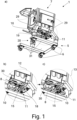
  • 1 eine portable Behälterhalterung mit einer Transportsicherung in a) perspektivischer Darstellung, b) einen Ausschnitt, welcher die Transportsicherung in einer Sicherungsposition zeigt, und c) einen Ausschnitt, welcher die Transportsicherung in einer Entsicherungsposition zeigt,
  • 2 die Transportsicherung gemäß 1 in a) der Sicherungsposition, wobei die Lage einer Antriebsstelle der Behälterhalterung gestrichelt angedeutet ist, und b) der Entsicherungsposition in perspektivischer Ansicht,
  • 3 ein zweites Ausführungsbeispiel einer Transportsicherung in a) der Sicherungsposition, wobei die Lage einer Antriebsstelle gestrichelt angedeutet ist, und b) der Entsicherungsposition in perspektivischer Ansicht,
  • 4 ein weiteres Ausführungsbeispiel einer Transportsicherung in a) der Sicherungsposition, wobei die Lage einer Antriebsstelle gestrichelt angedeutet ist, und b) der Entsicherungsposition in perspektivischer Ansicht und
  • 5 die portable Behälterhalterung gemäß 1 mit aufgenommenem Einwegbehälter und in a) ohne aufgenommene Antriebseinheit und Transportsicherung in Sicherungsposition und b) mit aufgenommener Antriebseinheit und Transportsicherung in Entsicherungsposition in seitlicher Schnittansicht.
In the following, the invention is explained in more detail with reference to a drawing which merely shows exemplary embodiments. In the drawing,
  • 1 a portable container holder with a transport lock in a) perspective view, b) a section showing the transport lock in a locking position, and c) a section showing the transport lock in a unlocking position,
  • 2 the transport security according to 1 in a) the securing position, with the position of a drive point of the container holder indicated by dashed lines, and b) the unlocking position in perspective view,
  • 3 a second embodiment of a transport lock in a) the locking position, with the position of a drive point indicated by dashed lines, and b) the unlocking position in perspective view,
  • 4 another embodiment of a transport lock in a) the locking position, with the position of a drive point indicated by dashed lines, and b) the unlocking position in perspective view and
  • 5 the portable container holder according to 1 with disposable container inserted and in a) without drive unit and transport lock in locking position and b) with drive unit and transport lock in unlocking position in a side sectional view.

Das in den 1a), 1b), 1c) sowie 5a), 5b) dargestellte und insoweit bevorzugte Ausführungsbeispiel betrifft eine portable Behälterhalterung 1 zum Halten und Transportieren eines mit Fluid 2, insbesondere einer Flüssigkeit, gefüllten Einwegbehälters 3. Bei dem Einwegbehälter 3 kann es sich insbesondere um einen in Bioprozessen einsetzbaren Einwegbehälter 3 handeln. Der Einwegbehälter 3 ist vorzugsweise flexibel, insbesondere nach Art eines Beutels, ausgebildet, so dass dessen Außenvolumen beim Befüllen mit Fluid 2 zunimmt. Bei dem Fluid 2 kann es sich insbesondere um ein in Bioprozessen eingesetztes Fluid 2 handeln, etwa um ein einen aufgereinigten pharmazeutischen Inhaltsstoff beinhaltendes Fluid 2 oder ein Kultivierungsmedium.The 1a) , 1b) , 1c ) and 5a), 5b) and in this respect preferred embodiment relates to a portable container holder 1 for holding and transporting a disposable container 3 filled with fluid 2, in particular a liquid. The disposable container 3 can in particular be a disposable container 3 that can be used in bioprocesses. The disposable container 3 is preferably flexible, in particular in the manner of a bag, so that its external volume increases when filled with fluid 2. The fluid 2 can in particular be a fluid 2 used in bioprocesses, for example a fluid 2 containing a purified pharmaceutical ingredient or a culture medium.

Der Einwegbehälter 3 hat ein magnetangetriebenes Mischelement 4 aufgenommen. Das Mischelement 4 kann frei rotierbar in dem Einwegbehälter 3 aufgenommen sein. Durch das Mischelement 4 lässt sich das Fluid 2 innerhalb des Einwegbehälters 3 durchmischen, etwa wenn ein Stoff zu dem Fluid 2 hinzugegeben wird oder um das Fluid 2 zu homogenisieren. Es ist möglich, dass das Fluid 2 während dem Halten des Einwegbehälters 3 mittels der portablen Behälterhalterung 1 über das Mischelement 4 durchmischt wird.The disposable container 3 has a magnetically driven mixing element 4. The mixing element 4 can be accommodated in the disposable container 3 in a freely rotatable manner. The mixing element 4 allows the fluid 2 to be mixed within the disposable container 3, for example when a substance is added to the fluid 2 or to homogenize the fluid 2. It is possible for the fluid 2 to be mixed while the disposable container 3 is being held by means of the portable container holder 1 via the mixing element 4.

„Portabel“ im Zusammenhang mit dieser Anmeldung bedeutet, dass die Behälterhalterung selbst transportierbar ist. Der Transport kann dabei sowohl mit aufgenommenem Einwegbehälter 3 als auch ohne aufgenommenen Einwegbehälter 3 erfolgen. Um die Behälterhalterung zu transportieren, kann diese, beispielsweise mittels eines Hubwagens, angehoben und verfahren werden. Auch ist es möglich, dass die Behälterhalterung eine Transportanordnung 5 mit Transportrollen 6 aufweist, wie es etwa vorzugsweise aus 1a) hervorgeht, über welche die Behälterhalterung verfahrbar ist.“Portable” in the context of this application means that the container holder itself is transportable. Transport can take place both with the disposable container 3 accommodated and without the disposable container 3 accommodated. In order to transport the container holder, it can be lifted and moved, for example by means of a lifting truck. It is also possible for the container holder to have a transport arrangement 5 with transport rollers 6, as is preferably the case with 1a) over which the container holder can be moved.

Die vorschlagsgemäße portable Behälterhalterung 1 weist eine Behälteraufnahme 7 zur Aufnahme des Einwegbehälters 3 auf. Der Einwegbehälter 3 kann insbesondere leer in der Behälteraufnahme 7 angeordnet und anschließend mit Fluid 2 befüllt werden. Die portable Behälterhalterung 1 ist vorzugsweise im Wesentlichen quaderförmig oder würfelförmig ausgebildet, wie es exemplarisch in 1a) abgebildet ist. Der mit Fluid 2 gefüllte Einwegbehälter 3, welcher in der Behälteraufnahme 7 aufgenommen ist und diese ausfüllt ist beispielhaft in den 5a), 5b) abgebildet. Es ist insbesondere möglich, dass der Einwegbehälter 3 nicht vollständig mit Fluid 2 gefüllt ist, sondern in einem Kopfbereich etwa Luft aufweist.The proposed portable container holder 1 has a container receptacle 7 for receiving the disposable container 3. The disposable container 3 can be arranged in the container receptacle 7 in particular empty and then filled with fluid 2. The portable container holder 1 is preferably essentially cuboid-shaped or cube-shaped, as is shown by way of example in 1a) The disposable container 3 filled with fluid 2, which is accommodated in the container holder 7 and fills it, is shown as an example in the 5a) , 5b) It is particularly possible that the disposable container 3 is not completely filled with fluid 2, but has air in a head region.

Die Behälteraufnahme 7 weist eine Antriebsstelle 8 auf, an welcher das Mischelement 4 im in der Behälteraufnahme 7 aufgenommenen Einwegbehälter 3 derart anordenbar ist, dass das Mischelement 4 durch eine Antriebseinheit 9 an der Antriebsstelle 8, insbesondere magnetisch, antreibbar ist. Über die Antriebsstelle 8 lässt sich das von dem Einwegbehälter 3 aufgenommene, also im Inneren des Einwegbehälters 3 angeordnete, Mischelement 4 berührungslos antreiben. Dies kann erfolgen, indem eine, insbesondere externe, Antriebseinheit 9 über ein Magnetfeld das Mischelement 4 in Rotation versetzt, so dass das Fluid 2 entsprechend durchmischt wird. Während der Durchmischung verbleibt das Mischelement 4 innerhalb des Einwegbehälters 3 in Kontakt mit dem Fluid 2. Das Mischelement 4 kann jedoch über die Antriebseinheit 9 berührungslos, also ohne Berührung zwischen dem Mischelement 4 und der Antriebseinheit 9, angetrieben werden.The container holder 7 has a drive point 8 at which the mixing element 4 can be arranged in the disposable container 3 accommodated in the container holder 7 in such a way that the mixing element 4 can be driven by a drive unit 9 at the drive point 8, in particular magnetically. The mixing element 4 accommodated by the disposable container 3, i.e. arranged inside the disposable container 3, can be driven contactlessly via the drive point 8. This can be done by a, in particular external, drive unit 9 setting the mixing element 4 in rotation via a magnetic field so that the fluid 2 is mixed accordingly. During mixing, the mixing element 4 remains in contact with the fluid 2 within the disposable container 3. The mixing element 4 can, however, be driven contactlessly via the drive unit 9, i.e. without contact between the mixing element 4 and the drive unit 9.

Während des Haltens, insbesondere des Durchmischens, und des Transports mit der portablen Behälterhalterung 1 verbleibt das Mischelement 4 in dem Einwegbehälter 3. Das magnetangetriebene 10 Mischelement 4 ist innerhalb des Einwegbehälters 3 grundsätzlich frei bewegbar und nicht im Inneren des Einwegbehälters 3 durch den Einwegbehälter 3 selbst positionsgebunden gelagert. Zwar ist es grundsätzlich möglich, dass das Mischelement 4 in dem Einwegbehälter 3 aufgenommen und an einer bestimmten Position, bspw. in einer Art Vertiefung, von einer Art Lagerdorn, oder ähnlichem, rotierbar gelagert ist, jedoch ist das Mischelement 4 an dieser Position innerhalb des Einwegbehälters 3 nicht positionsgebunden. Auch nach Anordnung des Mischelements 4 an der Antriebsstelle 8 bestünde insoweit grundsätzlich das Risiko, dass das Mischelement 4 innerhalb des Einwegbehälters 3 verrutscht, beispielsweise wenn es aus der vorstehend genannten Vertiefung herausfällt, von dem Lagerdorn abspringt, oder ähnliches.During holding, in particular mixing, and transport with the portable container holder 1, the mixing element 4 remains in the disposable container 3. The magnetically driven 10 mixing element 4 is generally freely movable within the disposable container 3 and is not fixed in position within the disposable container 3 by the disposable container 3 itself. Although it is generally possible for the mixing element 4 to be accommodated in the disposable container 3 and to be rotatably mounted in a certain position, for example in a type of recess, by a type of bearing mandrel, or the like, the mixing element 4 is not fixed in position at this position within the disposable container 3. Even after arranging the mixing element 4 at the drive point 8, there would be a risk that the mixing element 4 would slip within the disposable container 3, for example if it were to fall out of the aforementioned position. falls out of the recess, jumps off the bearing pin, or something similar.

Wesentlich bei der vorschlagsgemäßen portablen Behälterhalterung 1 ist daher nun, dass die portable Behälterhalterung 1 eine Transportsicherung 11 zum Sichern und Entsichern des an der Antriebsstelle 8, insbesondere innerhalb des Einwegbehälters 3, angeordneten Mischelements 4 in seiner Position aufweist, und dass die Transportsicherung 11 einen Magneten 10 aufweist, welcher zwischen einer definierten Sicherungsposition 12, in der das Mischelement 4, insbesondere durch das Magnetfeld des Magneten 10, positionsgesichert ist, und einer definierten Entsicherungsposition 13, in der das Mischelement 4 positionsentsichert ist, bewegbar ist.What is essential in the proposed portable container holder 1 is therefore that the portable container holder 1 has a transport lock 11 for securing and unlocking the mixing element 4 arranged at the drive point 8, in particular inside the disposable container 3, in its position, and that the transport lock 11 has a magnet 10 which is movable between a defined securing position 12, in which the mixing element 4 is secured in position, in particular by the magnetic field of the magnet 10, and a defined unlocking position 13, in which the mixing element 4 is unlocked in position.

Durch die Transportsicherung 11 der portablen Behälterhalterung 1 wird zuverlässig sichergestellt, dass das von dem Einwegbehälter 3 aufgenommene Mischelement 4 in Position haltbar ist. Das Mischelement 4 kann dadurch positionsgebunden sein, beispielsweise in der vorstehend genannten Vertiefung, an dem Lagerdorn oder ähnlichem. Insbesondere während des Transports, bei welchem es beispielsweise zu Erschütterungen kommen kann, kann das Verrutschen des Mischelements 4 damit vermieden werden.The transport lock 11 of the portable container holder 1 reliably ensures that the mixing element 4 held by the disposable container 3 is held in position. The mixing element 4 can therefore be fixed in position, for example in the recess mentioned above, on the bearing mandrel or the like. In particular during transport, during which vibrations can occur, for example, the mixing element 4 can thus be prevented from slipping.

Der Magnet 10 der Transportsicherung 11 sorgt in der definierten Sicherungsposition 12 (1b) über ein Magnetfeld dafür, dass das magnetangetriebene 10 Mischelement 4, innerhalb des Einwegbehälters 3 in Position gehalten wird und entsprechend positionsgesichert ist. Um das Mischelement 4 jedoch weiterhin etwa durch eine Antriebseinheit 9 antreiben zu können, lässt sich der Magnet 10 der Transportsicherung 11 bedarfsweise in die definierte Entsicherungsposition 13 (1c)) bewegen, in welcher das Mischelement 4 entsprechend positionsentsichert und sowohl antreibbar als auch rotierbar ist. Während des Durchmischens ist die Positionssicherung des Mischelements 4 im Allgemeinen nicht erforderlich, da das Mischelement 4 ohnehin durch das Magnetfeld der Antriebseinheit 9 in Position gehalten werden kann.The magnet 10 of the transport lock 11 ensures in the defined securing position 12 ( 1b) via a magnetic field, ensures that the magnetically driven 10 mixing element 4 is held in position within the disposable container 3 and is secured accordingly. However, in order to continue to be able to drive the mixing element 4, for example by a drive unit 9, the magnet 10 of the transport lock 11 can be moved into the defined release position 13 ( 1c )), in which the mixing element 4 is correspondingly position-locked and can be driven as well as rotated. During mixing, the position-locking of the mixing element 4 is generally not necessary, since the mixing element 4 can be held in position by the magnetic field of the drive unit 9 anyway.

„Positionsgesichert“ im Zusammenhang mit der Anmeldung umfasst insoweit, dass das von dem Einwegbehälter 3 aufgenommene Mischelement 4 von dem Magneten 10 der Transportsicherung 11 in einer bestimmten Position, insbesondere angeordnet an der Antriebsstelle 8, gehalten wird. In der definierten Sicherungsposition 12 des Magneten 10 wirkt dessen Magnetfeld auf das Mischelement 4.In the context of the application, “position-secured” means that the mixing element 4 received in the disposable container 3 is held in a specific position, in particular arranged at the drive point 8, by the magnet 10 of the transport lock 11. In the defined securing position 12 of the magnet 10, its magnetic field acts on the mixing element 4.

„Positionsentsichert“ im Zusammenhang mit der Anmeldung umfasst dahingegen, dass das Mischelement 4 entsprechend nicht von dem Magneten 10 der Transportsicherung 11 in Position gehalten wird. In der definierten Entsicherungsposition 13 des Magneten 10 wirkt dessen Magnetfeld, vorzugsweise, nicht auf das Mischelement 4 oder nur derart schwach auf das Mischelement 4, dass dieses nicht durch den Magneten 10 in Position gehalten wird.In contrast, “position unlocked” in the context of the application includes that the mixing element 4 is not held in position by the magnet 10 of the transport lock 11. In the defined unlocked position 13 of the magnet 10, its magnetic field preferably does not act on the mixing element 4 or only acts so weakly on the mixing element 4 that it is not held in position by the magnet 10.

„Definiert“ im Zusammenhang mit dieser Anmeldung und den Positionen umfasst, dass die Sicherungsposition 12 und die Entsicherungsposition 13 festgelegte Positionen sind, in welche der Magnet 10 wiederholt bewegbar ist. Die „definierte Sicherungsposition“ 12 kann damit insbesondere eine bestimmte Position sein, in welcher das Magnetfeld des Magneten 10 auf das Mischelement 4 wirkt, oder aber auch ein Winkelbereich sein, in welchem das Magnetfeld des Magneten 10 auf das Mischelement 4 wirkt. Die „definierte Entsicherungsposition“ 13 kann insbesondere eine bestimmte Position sein, in welcher das Magnetfeld des Magneten 10 nicht oder nur derart schwach, dass das Mischelement 4 nicht in Position gehalten wird, auf das Mischelement 4 wirkt, oder aber auch ein Winkelbereich sein, in welchem das Magnetfeld des Magneten 10 nicht oder nur derart schwach, dass das Mischelement 4 nicht in Position gehalten wird, auf das Mischelement 4 wirkt.“Defined” in the context of this application and the positions includes that the securing position 12 and the releasing position 13 are fixed positions into which the magnet 10 can be repeatedly moved. The “defined securing position” 12 can therefore be, in particular, a specific position in which the magnetic field of the magnet 10 acts on the mixing element 4, or else an angular range in which the magnetic field of the magnet 10 acts on the mixing element 4. The “defined releasing position” 13 can, in particular, be a specific position in which the magnetic field of the magnet 10 does not act on the mixing element 4, or only acts so weakly that the mixing element 4 is not held in position, or else an angular range in which the magnetic field of the magnet 10 does not act on the mixing element 4, or only acts so weakly that the mixing element 4 is not held in position.

In den 2a), 2b), 3a), 3b) sowie 4a), 4b) ist jeweils ein Ausführungsbeispiel einer Transportsicherung 11 der portablen Behälteraufnahme 7 abgebildet. In den 2a), 3a) und 4a) befindet sich die jeweilige Transportsicherung 11 dabei in der Sicherungsposition 12, in den 2b), 3b) und 4b) in der Entsicherungsposition 13. Die Transportsicherungen 11 sind in den Fig. entsprechend demontiert dargestellt, können jedoch bedarfsweise montiert werden, wie es etwa aus der 1 und 5a), 5b) hervorgeht. In den 2a), 3a) und 4a) ist die Lage einer möglichen Antriebsstelle 8 einer Behälterhalterung 1 gestrichelt dargestellt.In the 2a) , 2b) , 3a) , 3b) and 4a), 4b) each show an embodiment of a transport lock 11 of the portable container holder 7. In the 2a) , 3a) and 4a) the respective transport lock 11 is in the locking position 12, in the 2b) , 3b) and 4b) in the unlocking position 13. The transport locks 11 are shown dismantled in the figures, but can be mounted if required, as shown in the 1 and 5a) , 5b) In the 2a) , 3a) and 4a) the position of a possible drive point 8 of a container holder 1 is shown in dashed lines.

Es ist vorzugsweise vorgesehen, dass die Transportsicherung 11 eine Magnethalterung 14 zum Halten des Magnetes 10 in der Sicherungsposition 12 und der Entsicherungsposition 13 aufweist. Der Magnet 10 ist über die Magnethalterung 14 aus der Sicherungsposition 12, exemplarisch in den 2a), 3a) und 4a) abgebildet, in die Entsicherungsposition 13, exemplarisch in den 2b), 3b) und 4b) abgebildet, und/oder aus der Entsicherungsposition 13 in die Sicherungsposition 12 rotatorisch und/oder translatorisch, insbesondere linear, bewegbar. Vorzugsweise wird der Magnet 10 über die Magnethalterung 14 durch eine Schwenkbewegung rotatorisch bewegt, wie bei den Ausführungsbeispielen der 2a), 2b) oder 4a), 4b) umgesetzt, oder durch eine Schiebebewegung translatorisch, insbesondere linear, bewegt, wie bei dem Ausführungsbeispiel der 3a), 3b) umgesetzt. Es ist auch möglich, dass der Magnet 10 sowohl rotatorisch als auch translatorisch, insbesondere linear, bewegbar ist, indem dieser beispielsweise verschwenkt und verschoben wird, wobei diese Bewegungen insbesondere zeitgleich, zumindest teilweise zeitgleich oder nacheinander erfolgen können. Der Magnet 10 ist an der Magnethalterung 14 angeordnet.It is preferably provided that the transport lock 11 has a magnet holder 14 for holding the magnet 10 in the securing position 12 and the unlocking position 13. The magnet 10 can be moved via the magnet holder 14 from the securing position 12, for example into the 2a) , 3a) and 4a) shown, in the release position 13, exemplified in the 2b) , 3b) and 4b) shown, and/or can be moved rotationally and/or translatorily, in particular linearly, from the release position 13 into the securing position 12. Preferably, the magnet 10 is moved rotationally via the magnet holder 14 by a pivoting movement, as in the embodiments of the 2a) , 2b) or 4a) , 4b) implemented, or moved translationally, in particular linearly, by a sliding movement, as in the embodiment of the 3a) , 3b) implemented. It is also possible It is possible for the magnet 10 to be movable both rotationally and translationally, in particular linearly, by being pivoted and displaced, for example, whereby these movements can take place simultaneously, at least partially simultaneously, or one after the other. The magnet 10 is arranged on the magnet holder 14.

Bei den abgebildeten Ausführungsbeispielen und vorzugsweise weist die Magnethalterung 14 eine Magnetführung 15 zur geführten Bewegung des Magneten 10 zwischen der Sicherungsposition 12 und der Entsicherungsposition 13 auf, wobei die Magnetführung 15 ein Führungslager 16 und ein in dem Führungslager 16 bewegbar gelagertes Bewegungselement 17 aufweist. Das Bewegungselement 17 kann rotatorisch, wie in 2a), 2b) oder 4a), 4b) exemplarisch abgebildet, oder linearbeweglich, wie in 3a), 3b) exemplarisch abgebildet, in dem Führungslager 16 gelagert sein. Es ist möglich, dass die Magnethalterung 14 zwei bewegbar gelagerte Bewegungselemente 17 aufweist, wie es beispielhaft in 3a), 3b) dargestellt ist. Hier und vorzugsweise weist das Führungslager 16 zwei Führungsausnehmungen auf, in welchen die, insbesondere zylindrischen, Bewegungselemente 17 in Hauptachsrichtung beweglich gelagert sind und/oder in welchen die, insbesondere zylindrischen, Bewegungselemente 17 parallel zueinander gelagert sind. Der Magnet 10 kann, hier und vorzugsweise, einseitig an dem Bewegungselement 17 oder den Bewegungselementen 17, insbesondere starr, angeordnet sein. Der Magnet 10 kann insbesondere über ein oder mehrere Klemmelemente, wie etwa Klammern, oder Schraubelemente an dem Bewegungselement 17 oder den Bewegungselementen 17 angeordnet sein.In the illustrated embodiments and preferably, the magnet holder 14 has a magnet guide 15 for guided movement of the magnet 10 between the securing position 12 and the release position 13, wherein the magnet guide 15 has a guide bearing 16 and a movement element 17 movably mounted in the guide bearing 16. The movement element 17 can be rotational, as in 2a) , 2b) or 4a) , 4b) shown as an example, or linearly movable, as in 3a) , 3b) shown as an example, in the guide bearing 16. It is possible that the magnet holder 14 has two movably mounted movement elements 17, as shown for example in 3a) , 3b) is shown. Here and preferably, the guide bearing 16 has two guide recesses in which the, in particular cylindrical, movement elements 17 are mounted so as to be movable in the main axis direction and/or in which the, in particular cylindrical, movement elements 17 are mounted parallel to one another. The magnet 10 can, here and preferably, be arranged on one side of the movement element 17 or the movement elements 17, in particular rigidly. The magnet 10 can be arranged on the movement element 17 or the movement elements 17 in particular via one or more clamping elements, such as clamps, or screw elements.

Zur starren Befestigung der Magnetführung 15 an der Behälteraufnahme 7 weist die Magnethalterung 14 vorzugsweise eine Führungsbefestigung 18 zur starren Befestigung der Magnetführung 15 an der Behälteraufnahme 7 auf, wie es etwa aus den 1b) und 2a), 2b) ersichtlich ist. Es ist möglich, dass die Führungsbefestigung 18 mit der Behälteraufnahme 7 verschraubbar und/oder verklemmbar ist, beispielsweise über Schraubbolzen oder Klemmmittel. Hier und vorzugsweise ist die Magnethalterung 14 über die Führungsbefestigung 18 an einem Behälterboden 19 der Behälteraufnahme 7, insbesondere untergrundzugewandt, angeordnet. Die Führungsbefestigung 18 kann gegenüber der Behälteraufnahme 7 oder einer Antriebsaufnahme 20, welche später genauer erörtert wird, starr angeordnet sein. Über die Magnethalterung 14 ist der Magnet 10 vorzugsweise gegenüber der Behälteraufnahme 7 und/oder der Antriebsaufnahme 20 bewegbar.For rigid fastening of the magnet guide 15 to the container holder 7, the magnet holder 14 preferably has a guide fastening 18 for rigid fastening of the magnet guide 15 to the container holder 7, as can be seen from the 1b) and 2a) , 2b) It is possible that the guide fastening 18 can be screwed and/or clamped to the container holder 7, for example via screw bolts or clamping means. Here and preferably, the magnet holder 14 is arranged via the guide fastening 18 on a container base 19 of the container holder 7, in particular facing the ground. The guide fastening 18 can be arranged rigidly relative to the container holder 7 or a drive holder 20, which will be discussed in more detail later. The magnet 10 can preferably be moved relative to the container holder 7 and/or the drive holder 20 via the magnet holder 14.

Besonders vorzugsweise weist die Transportsicherung 11 eine Bedienanordnung 21 zur Bedienung der Transportsicherung 11 auf. Der Magnet 10 ist über die Bedienanordnung 21 aus der Sicherungsposition 12 in die Entsicherungsposition 13 und/oder aus der Entsicherungsposition 13 in die Sicherungsposition 12, insbesondere manuell und/oder automatisch, bewegbar. Zur manuellen und/oder automatischen Betätigung wird nachfolgend noch im Zusammenhang mit dem vorschlagsgemäßen Verfahren genauer eingegangen werden.The transport lock 11 particularly preferably has an operating arrangement 21 for operating the transport lock 11. The magnet 10 can be moved via the operating arrangement 21 from the securing position 12 to the unlocking position 13 and/or from the unlocking position 13 to the securing position 12, in particular manually and/or automatically. Manual and/or automatic actuation will be discussed in more detail below in connection with the proposed method.

Zur manuellen Betätigung der Bedienanordnung 21 ist es denkbar, dass die Bedienanordnung 21 ein Bedienelement 22 aufweist. Bei dem Ausführungsbeispiel der 3a), 3b) und vorzugsweise ist das Bedienelement 22 als Griff 23 ausgebildet, welcher durch einen Benutzer, insbesondere einhändig, betätigbar ist. Das Bedienelement 22 kann, hier und vorzugsweise, endseitig an einem oder mehreren Bewegungselementen 17 angeordnet sein und/oder, hier und vorzugsweise, zwei Bewegungselemente 17 miteinander verbinden.For manual operation of the operating arrangement 21, it is conceivable that the operating arrangement 21 has an operating element 22. In the embodiment of the 3a) , 3b) and preferably the operating element 22 is designed as a handle 23 which can be operated by a user, in particular with one hand. The operating element 22 can, here and preferably, be arranged at the end of one or more movement elements 17 and/or, here and preferably, connect two movement elements 17 to one another.

Im Zusammenhang mit der Bedienanordnung 21 hat es sich insbesondere als vorteilhaft herausgestellt, dass die Bedienanordnung 21 eine Arretieranordnung 24 zur Arretierung des Magneten 10 in der Sicherungsposition 12 und/oder der Entsicherungsposition 13 aufweist. Die Arretieranordnung 24 kann insbesondere ein Arretierelement 25 oder mehrere Arretierelemente 25 aufweisen. Es ist möglich, dass die Arretieranordnung 24 zwei Arretierelemente 25 aufweist, wobei über eines der Arretierelemente 25 der Magnet 10 in der Sicherungsposition 12 arretierbar und über das andere der Arretierelemente 25 der Magnet 10 in der Entsicherungsposition 13 arretierbar ist. Das Arretierelemente 25 kann oder die Arretierelemente 25 können jeweils vorzugsweise als, insbesondere einhändig, manuell betätigbare Rastbolzen ausgebildet sein, wie es etwa bei den Ausführungsbeispielen der 2a), 2b) sowie 3a), 3b) der Fall ist. Das Arretierelement 25 kann oder die Arretierelemente 25 können jeweils in eine Arretierstellung vorgespannt sein, so dass der Magnet 10 bei Erreichen der Sicherungsposition 12 und/oder der Entsicherungsposition 13 automatisch durch das Arretierelement 25 oder durch die Arretierelemente 25 arretiert wird. Die Arretieranordnung 24, insbesondere das Arretierelement 25 oder die Arretierelemente 25, können insbesondere manuell, vorzugsweise händisch durch einen Benutzer, entriegelbar sein.In connection with the operating arrangement 21, it has proven particularly advantageous that the operating arrangement 21 has a locking arrangement 24 for locking the magnet 10 in the securing position 12 and/or the release position 13. The locking arrangement 24 can in particular have one locking element 25 or several locking elements 25. It is possible for the locking arrangement 24 to have two locking elements 25, wherein the magnet 10 can be locked in the securing position 12 via one of the locking elements 25 and the magnet 10 can be locked in the release position 13 via the other of the locking elements 25. The locking element 25 can be or the locking elements 25 can each preferably be designed as locking bolts that can be operated manually, in particular with one hand, as is the case in the embodiments of the 2a) , 2b) and 3a), 3b). The locking element 25 or the locking elements 25 can each be pre-tensioned into a locking position, so that the magnet 10 is automatically locked by the locking element 25 or by the locking elements 25 when the securing position 12 and/or the unlocking position 13 is reached. The locking arrangement 24, in particular the locking element 25 or the locking elements 25, can in particular be unlocked manually, preferably by hand by a user.

Alternativ oder zusätzlich kann die Bedienanordnung 21 eine Vorspannanordnung 26, insbesondere mit einem Federelement 27, zur Vorspannung des Magnetes 10 in die Sicherungsposition 12 oder die Entsicherungsposition 13 aufweisen. Es ist denkbar, dass das Federelement 27 als Drehfeder oder als Zugfeder oder als Druckfeder ausgebildet ist. Über die Vorspannanordnung 26 kann der Magnet 10 aus der Sicherungsposition 12 in die Entsicherungsposition 13 oder aus der Entsicherungsposition 13 in die Sicherungsposition 12 automatisch bewegt werden, beispielsweise wenn die Arretieranordnung 24, insbesondere das Arretierelement 25 oder die Arretierelemente 25, durch einen Benutzer entriegelt werden. Es ist insbesondere denkbar, dass der Magnet 10 von der Sicherungsposition 12 in die Entsicherungsposition 13 manuell und von der Entsicherungsposition 13 in die Sicherungsposition 12 automatisch durch die Vorspannanordnung 26 bewegt wird. Alternativ ist es möglich, dass der Magnet 10 von der Entsicherungsposition 13 in die Sicherungsposition 12 automatisch durch die Vorspannanordnung 26 und von der Sicherungsposition 12 in die Entsicherungsposition 13 manuell bewegt wird.Alternatively or additionally, the operating arrangement 21 can have a pre-tensioning arrangement 26, in particular with a spring element 27, for pre-tensioning the magnet 10 into the securing position 12 or the unlocking position 13. It is conceivable that the spring element 27 is designed as a torsion spring or as a tension spring or as a compression spring. The magnet 10 can be moved from the securing position 12 into the unlocking position 13 via the pre-tensioning arrangement 26. locking position 13 or from the unlocking position 13 to the securing position 12, for example when the locking arrangement 24, in particular the locking element 25 or the locking elements 25, are unlocked by a user. It is particularly conceivable that the magnet 10 is moved from the securing position 12 to the unlocking position 13 manually and from the unlocking position 13 to the securing position 12 automatically by the pre-tensioning arrangement 26. Alternatively, it is possible for the magnet 10 to be moved from the unlocking position 13 to the securing position 12 automatically by the pre-tensioning arrangement 26 and from the securing position 12 to the unlocking position 13 manually.

Hier und vorzugsweise ist vorgesehen, dass der Magnet 10 als Dauermagnet ausgebildet ist. Der Magnet 10 kann als Material Eisen, Kobalt und/oder Nickel umfassen. Alternativ oder zusätzlich weist der Magnet 10 eine Magnetausnehmung 28 auf. Die Magnetausnehmung 28 kann in der Sicherungsposition 12 des Magneten 10 das Mischelement 4 im in der Behälteraufnahme 7 aufgenommenen Einwegbehälter 3 zumindest teilweise umgeben, so wie es beispielsweise aus Fig. 5a) hervorgeht.Here and preferably, it is provided that the magnet 10 is designed as a permanent magnet. The magnet 10 can comprise iron, cobalt and/or nickel as the material. Alternatively or additionally, the magnet 10 has a magnet recess 28. In the securing position 12 of the magnet 10, the magnet recess 28 can at least partially surround the mixing element 4 in the disposable container 3 received in the container receptacle 7, as can be seen, for example, in Fig. 5a) emerges.

Im Zusammenhang mit der Ausgestaltung des Magneten 10 ist es denkbar, dass die Magnetausnehmung 28 derart ausgebildet ist, dass der Magnet 10 einen, insbesondere in der Sicherungsposition 12 horizontalen, Querschnitt aufweist, der im Wesentlichen einen Kreis, einen Teilkreis, wie in den 2a), 2b) und 4a), 4b) beispielhaft dargestellt, ein Hufeisen, wie in den 3a), 3b) beispielhaft dargestellt, eine Ellipse oder eine Teilellipse darstellt. Der Magnet 10 kann insbesondere einseitig offen, insbesondere entlang dessen Umfang, ausgebildet sein. Es ist vorzugsweise denkbar, dass der Magnet 10 in der Sicherungsposition 12 das Mischelement 4, insbesondere den Rührer, wie etwa einen Impeller, zumindest teilweise umgibt.In connection with the design of the magnet 10, it is conceivable that the magnet recess 28 is designed such that the magnet 10 has a cross-section, in particular in the securing position 12, which is horizontal, which essentially forms a circle, a partial circle, as in the 2a) , 2b) and 4a) , 4b) For example, a horseshoe, as in the 3a) , 3b) shown by way of example, represents an ellipse or a partial ellipse. The magnet 10 can in particular be designed to be open on one side, in particular along its circumference. It is preferably conceivable that the magnet 10 in the securing position 12 at least partially surrounds the mixing element 4, in particular the stirrer, such as an impeller.

Die Magnetausnehmung 28 kann kreisrund, wie in den 2a), 2b) und 4a), 4b) beispielhaft dargestellt, ausgebildet sein. Vorzugsweise ist die Magnetausnehmung 28 als Positionierhilfe zur vereinfachten Positionierung des Magneten 10 an der Antriebsstelle 8 und/oder um das Mischelement 4 ausgebildet. Hier und vorzugsweise ist die Magnetausnehmung 28 korrespondierend zu der Antriebsstelle 8 und/oder dem Mischelement 4 ausgebildet.The magnet recess 28 can be circular, as in the 2a) , 2b) and 4a) , 4b) shown by way of example. Preferably, the magnet recess 28 is designed as a positioning aid for simplified positioning of the magnet 10 at the drive point 8 and/or around the mixing element 4. Here and preferably, the magnet recess 28 is designed to correspond to the drive point 8 and/or the mixing element 4.

Hinsichtlich der Behälteraufnahme 7 ist vorzugsweise vorgesehen, dass die Behälteraufnahme 7 ein oder mehrere, hier und vorzugsweise zumindest vier, Behälterwände 29 und einem Behälterboden 19 aufweist. Die Antriebsstelle 8 ist an dem Behälterboden 19 angeordnet. Bei dem Ausführungsbeispiel der 1a) und vorzugsweise sind jeweils zwei der vier Behälterwände 29 im Wesentlichen senkrecht zueinander angeordnet. Der Behälterboden 19 kann die Behälteraufnahme 7 einseitig begrenzen. Die Behälteraufnahme 7 kann, hier und vorzugsweise, einseitig offen ausgebildet sein, so dass ein Einwegbehälter 3 in der Behälteraufnahme 7 aufnehmbar ist. Es ist insbesondere denkbar, dass der Einwegbehälter 3 durch eine Abdeckung abdeckbar und die Behälteraufnahme 7 durch die Abdeckung auf der offenen Seite geschlossen wird. Hier und vorzugsweise weist zumindest eine der Behälterwände 29 eine schließbare Seitentür auf oder wird von einer solchen gebildet. Die Behälteraufnahme 7 kann im Wesentlichen quaderförmig, insbesondere kubisch, ausgebildet sein, wie es exemplarisch in 1a) abgebildet ist.With regard to the container receptacle 7, it is preferably provided that the container receptacle 7 has one or more, here and preferably at least four, container walls 29 and a container bottom 19. The drive point 8 is arranged on the container bottom 19. In the embodiment of the 1a) and preferably two of the four container walls 29 are arranged essentially perpendicular to each other. The container base 19 can delimit the container receptacle 7 on one side. The container receptacle 7 can, here and preferably, be designed to be open on one side, so that a disposable container 3 can be received in the container receptacle 7. It is particularly conceivable that the disposable container 3 can be covered by a cover and the container receptacle 7 is closed by the cover on the open side. Here and preferably at least one of the container walls 29 has a closable side door or is formed by such a door. The container receptacle 7 can be designed essentially cuboid-shaped, in particular cubic, as is shown by way of example in 1a) is shown.

Alternativ oder zusätzlich ist es denkbar, dass die Antriebsstelle 8 eine, insbesondere im Wesentlichen kreisförmige oder elliptische, Antriebsausnehmung 30 aufweist, welche sich über die gesamte Dicke des Behälterbodens 19 erstreckt und in welcher das Mischelement 4 zumindest teilweise oder die Antriebseinheit 9 oder der Magnet 10 zumindest teilweise anordenbar ist. Aus 1c) ist die kreisförmige Antriebsausnehmung 30 beispielhaft ersichtlich.Alternatively or additionally, it is conceivable that the drive point 8 has a, in particular substantially circular or elliptical, drive recess 30 which extends over the entire thickness of the container bottom 19 and in which the mixing element 4 can be arranged at least partially or the drive unit 9 or the magnet 10 can be arranged at least partially. 1c ), the circular drive recess 30 can be seen as an example.

Es ist vorzugsweise vorgesehen, dass der Magnet 10 in der Sicherungsposition 12 an der Antriebsstelle 8, insbesondere koaxial zur Antriebsausnehmung 30, angeordnet ist. In 5a) befindet sich der Magnet 10 in der Sicherungsposition 12. Das Mischelement 4, insbesondere der Rührer, bevorzugt der Impeller, des Einwegbehälters 3 ist an der Antriebsstelle 8 angeordnet. Der in der Sicherungsposition 12 ebenfalls an der Antriebsstelle 8 angeordnete Magnet 10 sichert so das Mischelement 4, insbesondere den Rührer, vorzugsweise den Impeller, und verhindert, dass dieser innerhalb des Einwegbehälters 3, etwa während des Transports, verrutscht. Das Mischelement 4, insbesondere der Rührer, vorzugsweise der Impeller, ist damit positionsgesichert. In 5a) abgebildet und vorzugsweise ist der Magnet 10 in der Sicherungsposition 12 einseitig an der an dem Behälterboden 19 angeordneten Antriebsstelle 8, insbesondere untergrundzugewandt, angeordnet. Es ist möglich, dass der Magnet 10 in der Sicherungsposition 12 an dem Behälterboden 19 anliegt. Hier und vorzugsweise ist der Magnet 10 in der Sicherungsposition 12 horizontal ausgerichtet.It is preferably provided that the magnet 10 is arranged in the securing position 12 at the drive point 8, in particular coaxially to the drive recess 30. In 5a) the magnet 10 is in the securing position 12. The mixing element 4, in particular the stirrer, preferably the impeller, of the disposable container 3 is arranged at the drive point 8. The magnet 10, which is also arranged at the drive point 8 in the securing position 12, thus secures the mixing element 4, in particular the stirrer, preferably the impeller, and prevents it from slipping within the disposable container 3, for example during transport. The mixing element 4, in particular the stirrer, preferably the impeller, is thus secured in position. In 5a) shown and preferably the magnet 10 in the securing position 12 is arranged on one side of the drive point 8 arranged on the container base 19, in particular facing the ground. It is possible for the magnet 10 in the securing position 12 to rest against the container base 19. Here and preferably the magnet 10 in the securing position 12 is aligned horizontally.

Um das Mischelement 4 durch eine externe Antriebseinheit 9 antreiben zu können, ist etwa bei dem Ausführungsbeispiel gemäß 1a) und 5a), 5b) und vorzugsweise vorgesehen, dass die portable Behälterhalterung 1 eine Antriebsaufnahme 20 zur Aufnahme der Antriebseinheit 9 aufweist, welche unterhalb der Behälteraufnahme 7 angeordnet ist. Die Antriebsaufnahme 20 ist derart ausgebildet, dass die Antriebseinheit 9 in dieser anordenbar ist, so dass das Mischelement 4 entsprechend antreibbar ist. Aus konstruktiver Sicht ist möglich, dass die Antriebsaufnahme 20 durch den Behälterboden 19 der Behälteraufnahme 7 nach oben hin begrenzt ist, so wie es beispielsweise aus 1a) ersichtlich ist.In order to be able to drive the mixing element 4 by an external drive unit 9, for example in the embodiment according to 1a) and 5a) , 5b) and preferably provided that the portable container holder 1 has a drive receptacle 20 for receiving the drive unit 9, which is arranged below the container receptacle 7. The drive receptacle 20 is designed in such a way that the drive unit 9 can be arranged in it, so that the mixing element 4 can be driven accordingly. From a design point of view, it is possible that the drive receptacle 20 is limited at the top by the container bottom 19 of the container receptacle 7, as is the case, for example, with 1a) is evident.

Hinsichtlich der Portabilität der Behälterhalterung hat es sich als überaus vorteilhaft herausgestellt, dass die portable Behälterhalterung 1 eine Transportanordnung 5 mit mehreren Transportrollen 6 zum Verfahren der portablen Behälterhalterung 1 aufweist. Durch die Transportrollen 6 lässt sich die Behälterhalterung rollend bewegen, etwa um den in der Behälteraufnahme 7 aufgenommenen Einwegbehälter 3 zu transportieren. In dem Ausführungsbeispiel der 1a) und vorzugsweise weist die Transportanordnung 5 vier Transportrollen 6 auf. Zumindest ein Teil, insbesondere zwei, der Transportrollen 6 kann vorzugsweise arretierbar sein. Hierdurch kann die portable Behälterhalterung 1 am unbeabsichtigten Bewegen gehindert werden.With regard to the portability of the container holder, it has proven to be extremely advantageous that the portable container holder 1 has a transport arrangement 5 with several transport rollers 6 for moving the portable container holder 1. The container holder can be moved in a rolling manner by means of the transport rollers 6, for example in order to transport the disposable container 3 accommodated in the container holder 7. In the embodiment of the 1a) and preferably the transport arrangement 5 has four transport rollers 6. At least one part, in particular two, of the transport rollers 6 can preferably be lockable. This can prevent the portable container holder 1 from moving unintentionally.

Hier und vorzugsweise ist vorgesehen, dass die Antriebsaufnahme 20 zumindest aus mehreren Trägern 31 und/oder Platten gebildet ist, wobei die Antriebsaufnahme 20 zumindest zweiseitig, insbesondere dreiseitig, durch die mehreren Träger 31 und/oder Platten begrenzt ist. Die Träger 31 können die Lastaufnahme ermöglichen. Hier und vorzugsweise umfassen die Träger 31 mehrere VertikalTräger, welche vertikal angeordnet sind, und mehrere Horizontal-Träger auf. In dem Ausführungsbeispiel gemäß 1a) wird die Antriebsaufnahme 20 aus drei Vertikal-Trägern und drei Horizontal-Trägern gebildet. Es ist denkbar, dass eine Platte oder mehrere Platten an den Trägern 31 angeordnet sind, um etwa die in der Antriebsaufnahme 20 aufnehmbaren Antriebseinheit 9 vor äußeren Einflüssen zu schützen. Vorzugsweise sind die Transportrollen 6 an der Antriebsaufnahme 20, insbesondere an den Trägern 31 und/oder Platten angeordnet. Aus 1a) ersichtlich und vorzugsweise ist die Antriebsaufnahme 20 bodenfrei ausgebildet. Hierdurch lässt sich eine Antriebseinheit 9, etwa schiebend, in die Antriebsaufnahme 20 bewegen. Hier und vorzugsweise ist die Antriebsaufnahme 20 zumindest einseitig geöffnet.Here and preferably it is provided that the drive mount 20 is formed from at least several supports 31 and/or plates, wherein the drive mount 20 is limited on at least two sides, in particular three sides, by the several supports 31 and/or plates. The supports 31 can enable the load to be carried. Here and preferably the supports 31 comprise several vertical supports, which are arranged vertically, and several horizontal supports. In the embodiment according to 1a) the drive holder 20 is formed from three vertical supports and three horizontal supports. It is conceivable that one plate or several plates are arranged on the supports 31 in order to protect the drive unit 9 that can be accommodated in the drive holder 20 from external influences. Preferably, the transport rollers 6 are arranged on the drive holder 20, in particular on the supports 31 and/or plates. 1a) and preferably the drive receptacle 20 is designed to be free from the floor. This allows a drive unit 9 to be moved, for example by sliding, into the drive receptacle 20. Here and preferably the drive receptacle 20 is open at least on one side.

Neben der vorschlagsgemäßen portablen Behälterhalterung 1 wird darüber hinaus ein System 32 zur Verwendung in einem Bioprozess vorgeschlagen, wobei das System 32 eine portable Behälterhalterung 1, insbesondere eine vorschlagsgemäße portable Behälterhalterung, mit einer Behälteraufnahme 7 und einen Einwegbehälter 3, der ein magnetangetriebenes Mischelement 4 zum Durchmischen eines Fluids 2 aufgenommen hat, aufweist, wobei der Einwegbehälter 3 in der Behälteraufnahme 7 aufgenommen ist, die Behälteraufnahme 7 eine Antriebsstelle 8 aufweist und das Mischelement 4 im in der Behälteraufnahme 7 aufgenommenen Einwegbehälter 3 derart an der Antriebsstelle 8 der Behälteraufnahme 7 angeordnet ist, dass das Mischelement 4 durch eine Antriebseinheit 9, insbesondere magnetisch, antreibbar ist.In addition to the proposed portable container holder 1, a system 32 for use in a bioprocess is also proposed, wherein the system 32 has a portable container holder 1, in particular a proposed portable container holder, with a container holder 7 and a disposable container 3, which has received a magnetically driven mixing element 4 for mixing a fluid 2, wherein the disposable container 3 is received in the container holder 7, the container holder 7 has a drive point 8 and the mixing element 4 in the disposable container 3 received in the container holder 7 is arranged at the drive point 8 of the container holder 7 in such a way that the mixing element 4 can be driven by a drive unit 9, in particular magnetically.

Wesentlich ist bei dem vorschlagsgemäßen System 32, dass die portable Behälterhalterung 1 eine Transportsicherung 11 zum Sichern und Entsichern des an der Antriebsstelle 8 angeordneten Mischelements 4 in seiner Position aufweist, wobei die Transportsicherung 11 einen Magneten 10 aufweist, welcher zwischen einer definierten Sicherungsposition 12, in der das Mischelement 4 positionsgesichert ist, und einer definierten Entsicherungsposition 13, in der das Mischelement 4 positionsentsichert ist, bewegbar ist. Ein vorschlagsgemäßes System 32 ist exemplarisch in den 5a), 5b) dargestellt.What is essential in the proposed system 32 is that the portable container holder 1 has a transport lock 11 for securing and unlocking the mixing element 4 arranged at the drive point 8 in its position, wherein the transport lock 11 has a magnet 10 which can be moved between a defined securing position 12 in which the mixing element 4 is secured in position and a defined unlocking position 13 in which the mixing element 4 is unlocked in position. A proposed system 32 is shown by way of example in the 5a) , 5b) shown.

Auf alle Ausführungen zu der vorschlagsgemäßen portablen Behälterhalterung 1 darf verwiesen werden.Reference may be made to all statements relating to the proposed portable container holder 1.

Vorzugsweise ist vorgesehen, dass der Einwegbehälter 3 als flexibler Einwegbehälter 3 ausgebildet ist. Der flexible Einwegbehälter 3 ist forminstabil. Durch Aufnahme des Einwegbehälters 3 in der Behälteraufnahme 7 wird der Einwegbehälter 3 gehalten und ist mit Fluid 2 befüllbar. Der mit Fluid 2 gefüllte Einwegbehälter 3 kommt an der Behälteraufnahme 7 zur Anlage und wird so gehalten, wie es exemplarisch aus den 5a), 5b) ersichtlich ist. Hier und vorzugsweise ist der Einwegbehälter 3 nach Art eines flexiblen Beutels ausgebildet. Alternativ oder zusätzlich ist der Einwegbehälter 3 steril ausgebildet. Insbesondere im Bereich der Biotechnologie kann dies für den Einsatz maßgebend sein, indem Kontaminationen des in dem Einwegbehälter 3 aufgenommenen Fluids 2 vermeidbar sind. Der Einwegbehälter 3 kann insbesondere als Bioreaktor und/oder Kultivierungsbehälter ausgebildet sein.Preferably, the disposable container 3 is designed as a flexible disposable container 3. The flexible disposable container 3 is dimensionally unstable. By receiving the disposable container 3 in the container holder 7, the disposable container 3 is held and can be filled with fluid 2. The disposable container 3 filled with fluid 2 comes to rest on the container holder 7 and is held in such a way as is shown by way of example in the 5a) , 5b) is visible. Here and preferably, the disposable container 3 is designed in the manner of a flexible bag. Alternatively or additionally, the disposable container 3 is designed to be sterile. In particular in the field of biotechnology, this can be decisive for use in that contamination of the fluid 2 held in the disposable container 3 can be avoided. The disposable container 3 can in particular be designed as a bioreactor and/or cultivation container.

Vorzugsweise ist vorgesehen, dass das Mischelement 4 als Rührer, insbesondere als Impeller, ausgebildet ist. In 5b) ist das als Impeller ausgebildete Mischelement 4 abgebildet. Das Mischelement 4, insbesondere der Rührer, vorzugsweise der Impeller, ist, hier und vorzugsweise, schaftlos und/oder wellenlos ausgebildet. Das Mischelement 4, insbesondere der Rührer, vorzugsweise der Impeller, kann insbesondere rotationssymmetrisch ausgebildet sein. Es ist denkbar, dass das Mischelement 4, insbesondere der Rührer, vorzugsweise der Impeller, ein einstückiges Gehäuse aufweist, in welchem insbesondere ein dauermagnetisches Material und/oder ein magnetisches Material, wie Eisen, Kobalt oder Nickel, aufgenommen ist.Preferably, the mixing element 4 is designed as a stirrer, in particular as an impeller. In 5b) the mixing element 4 designed as an impeller is shown. The mixing element 4, in particular the stirrer, preferably the impeller, is, here and preferably, designed without a shaft and/or a shaft. The mixing element 4, in particular the stirrer, preferably the impeller, can in particular be designed to be rotationally symmetrical. It is conceivable that the mixing element 4, in particular the stirrer, preferably the impeller, has a one-piece housing in which in particular a permanent magnetic material and/or a magnetic material, such as iron, cobalt or nickel, is accommodated.

Besonders vorzugsweise weist das System 32 eine Antriebseinheit 9 auf. Die Antriebseinheit 9 kann, wie in 5b) dargestellt und vorzugsweise als externe Antriebseinheit 9 ausgebildet sein, welche vorzugsweise separat, also als eigenständige Einheit, von der portablen Behälterhalterung 1 ausgebildet ist. Die Antriebseinheit 9 kann bedarfsweise an der Antriebsstelle 8 anordenbar sein. Vorzugsweise ist die Antriebseinheit 9 durch die Antriebsaufnahme 20 der Behälterhalterung aufnehmbar. Es ist in diesem Zusammenhang vorzugsweise möglich, dass die Antriebseinheit 9 in der Antriebsaufnahme 20 anordenbar oder aus der Antriebsaufnahme 20 entfernbar ist, indem die Antriebseinheit 9 und/oder die portable Behälterhalterung 1 schiebend und/oder ziehend bewegbar ist. In 5b) ist die Antriebseinheit 9 durch Schieben oder Ziehen in die Antriebsaufnahme 20 oder aus der Antriebsaufnahme 20 heraus bewegbar.Particularly preferably, the system 32 has a drive unit 9. The drive unit 9 can, as in 5b) and preferably designed as an external drive unit 9, which is preferably designed separately, i.e. as an independent unit, from the portable container holder 1. The drive unit 9 can be arranged at the drive point 8 if required. The drive unit 9 can preferably be accommodated by the drive receptacle 20 of the container holder. In this context, it is preferably possible for the drive unit 9 to be arranged in the drive receptacle 20 or to be removed from the drive receptacle 20 by the drive unit 9 and/or the portable container holder 1 being movable by pushing and/or pulling. In 5b) the drive unit 9 can be moved by pushing or pulling into or out of the drive receptacle 20.

Es wird ferner ein Verfahren zum Halten und Transportieren eines Einwegbehälters 3, unter Verwendung einer portablen Behälterhalterung 1, insbesondere einer vorschlagsgemäßen portablen Behälterhalterung, vorgeschlagen, wobei der Einwegbehälter 3 in einer Behälteraufnahme 7 der portablen Behälterhalterung 1 aufgenommen wird und ein magnetangetriebenes Mischelement 4 zum Durchmischen eines Fluids 2, welches in dem Einwegbehälter 3 aufgenommen ist, derart an einer Antriebsstelle 8 der portablen Behälterhalterung 1 angeordnet wird, dass das Mischelement 4 durch eine Antriebseinheit 9 antreibbar ist. Furthermore, a method for holding and transporting a disposable container 3 using a portable container holder 1, in particular a portable container holder according to the proposal, is proposed, wherein the disposable container 3 is received in a container receptacle 7 of the portable container holder 1 and a magnetically driven mixing element 4 for mixing a fluid 2 which is received in the disposable container 3 is arranged at a drive point 8 of the portable container holder 1 in such a way that the mixing element 4 can be driven by a drive unit 9.

Wesentlich bei dem vorschlagsgemäßen Verfahren ist, dass das an der Antriebsstelle 8 angeordnete Mischelement 4 durch eine Transportsicherung 11 der portablen Behälterhalterung 1, welche Transportsicherung 11 einen Magneten 10 aufweist, in seiner Position gesichert wird, indem der Magnet 10, insbesondere aus einer definierten Entsicherungsposition 13, in der das Mischelement 4 positionsentsichert ist, in eine definierte Sicherungsposition 12, in der das Mischelement 4 positionsgesichert ist, bewegt wird.What is essential in the proposed method is that the mixing element 4 arranged at the drive point 8 is secured in its position by a transport lock 11 of the portable container holder 1, which transport lock 11 has a magnet 10, by moving the magnet 10, in particular from a defined unlocking position 13, in which the mixing element 4 is unlocked in position, to a defined securing position 12, in which the mixing element 4 is secured in position.

Die im Verfahren eingesetzte portable Behälterhalterung 1 kann insbesondere Teil eines vorschlagsgemäßen Systems 32 sein.The portable container holder 1 used in the method can in particular be part of a proposed system 32.

Auf alle Ausführungen zu der vorschlagsgemäßen portable Behälterhalterung 1 und dem vorschlagsgemäßen System 32 darf verwiesen werden.Reference may be made to all statements relating to the proposed portable container holder 1 and the proposed system 32.

Vorzugsweise ist bei dem Verfahren vorgesehen, dass die Position des an der Antriebsstelle 8 angeordneten Mischelements 4 durch die Transportsicherung 11 der portablen Behälterhalterung 1 positionsentsichert wird, indem der Magnet 10 in eine definierte Entsicherungsposition 13 bewegt wird. Der Magnet 10 kann zwischen der Sicherungsposition 12 und der Entsicherungsposition 13 hin und her bewegt werden. In der Entsicherungsposition 13 ist das Mischelement 4 antreibbar. So lässt sich das in dem Einwegbehälter 3 aufgenommene Fluid 2 durchmischen.Preferably, the method provides that the position of the mixing element 4 arranged at the drive point 8 is unlocked by the transport lock 11 of the portable container holder 1 by moving the magnet 10 into a defined unlocking position 13. The magnet 10 can be moved back and forth between the locking position 12 and the unlocking position 13. The mixing element 4 can be driven in the unlocking position 13. In this way, the fluid 2 held in the disposable container 3 can be mixed.

Hinsichtlich der Bewegung des Magneten 10 ist vorzugsweise vorgesehen, dass der Magnet 10 zwischen der Sicherungsposition 12 und der Entsicherungsposition 13 schwenkend bewegt wird. Dies ist etwa bei der in den 2a), 2b) sowie 4a), 4b) abgebildeten Transportsicherungen 11 der Fall. Alternativ ist es ebenso denkbar, dass der Magnet 10 zwischen der Sicherungsposition 12 und der Entsicherungsposition 13 translatorisch, insbesondere linear, bewegt wird. Bei der Ausführung der Transportsicherung 11 gemäß 3a), 3b) ist der Magnet 10 zwischen der Sicherungsposition 12 und der Entsicherungsposition 13 linear bewegbar. Es ist ebenso denkbar, dass der Magnet 10 schwenkend und translatorisch, insbesondere linear, bewegt wird. Hierbei kann der Magnet 10 beispielsweise zunächst linear verschoben und anschließend verschwenkt werden.With regard to the movement of the magnet 10, it is preferably provided that the magnet 10 is moved in a pivoting manner between the securing position 12 and the releasing position 13. This is the case, for example, in the 2a) , 2b) and 4a), 4b). Alternatively, it is also conceivable that the magnet 10 is moved translationally, in particular linearly, between the securing position 12 and the unlocking position 13. When the transport securing device 11 is designed according to 3a) , 3b) the magnet 10 can be moved linearly between the securing position 12 and the releasing position 13. It is also conceivable that the magnet 10 is moved in a pivoting and translational manner, in particular linearly. In this case, the magnet 10 can, for example, first be moved linearly and then pivoted.

Es hat sich als besonders bevorzugt herausgestellt, dass der Magnet 10 zwischen der Sicherungsposition 12 und/oder der Entsicherungsposition 13 manuell und/oder automatisch bewegt wird.It has been found to be particularly preferred that the magnet 10 is moved manually and/or automatically between the securing position 12 and/or the releasing position 13.

„Manuell“ im Zusammenhang mit dieser Anmeldung umfasst Bewegungen, in denen die Bewegung des Magneten 10, insbesondere vollständig, durch einen Benutzer erfolgt. Der Benutzer kann den Magneten 10 etwa über die Bedienanordnung 21 direkt bewegen, indem dieser beispielsweise an dem Bedienelement 22 zieht oder drückt oder über das Bedienelement 22 den Magneten 10 verschwenkt, oder den Magneten 10 über die Bedienanordnung 21 indirekt bewegen, indem dieser beispielsweise den Magneten 10 über die Bedienanordnung 21 beim Einschieben oder Einziehen der Antriebseinheit 9 in die Antriebsaufnahme 20 bewegt.“Manually” in the context of this application includes movements in which the movement of the magnet 10, in particular completely, is carried out by a user. The user can move the magnet 10 directly via the operating arrangement 21, for example by pulling or pushing on the operating element 22 or pivoting the magnet 10 via the operating element 22, or move the magnet 10 indirectly via the operating arrangement 21, for example by moving the magnet 10 via the operating arrangement 21 when inserting or retracting the drive unit 9 into the drive receptacle 20.

„Automatisch“ im Zusammenhang mit dieser Anmeldung umfasst Bewegungen, die durch einen Motor oder eine Vorspannanordnung 26, insbesondere ein Federelement 27, erfolgen, ohne dass der Benutzer die Bewegung durchführt. Die Bewegungen können durch den Benutzer initiiert sein, etwa durch einen vom Benutzer ausgelösten Steuerbefehl oder das Entriegeln der Arretieranordnung 24 durch einen Benutzer."Automatic" in the context of this application includes movements that are carried out by a motor or a preloading arrangement 26, in particular a spring element 27, without the user performing the movement. The movements can be initiated by the user, for example by a control command triggered by the user or the unlocking of the locking arrangement 24 by a user.

So ist es im einfachsten Fall etwa denkbar, dass der Magnet 10 aus der Sicherungsposition 12 in die Entsicherungsposition 13 und aus der Entsicherungsposition 13 in die Sicherungsposition 12 manuell bewegt wird. Die Bedienanordnung 21 kann, hier und vorzugsweise, vorspannanordnungslos 26 ausgebildet und der Magnet 10 unvorgespannt sein. Der Magnet 10 kann in diesem Fall, insbesondere ausschließlich, über eine Bedienanordnung 21, insbesondere ein Bedienelement 22, zwischen der Sicherungsposition 12 und der Entsicherungsposition 13 manuell bewegt werden.In the simplest case, it is conceivable that the magnet 10 is moved manually from the safety position 12 to the release position 13 and from the release position 13 to the safety position 12. The operating arrangement 21 can, here and preferably, be designed without a pre-tensioning arrangement 26 and the magnet 10 can be unpre-tensioned. The magnet 10 can in this case be moved manually, in particular exclusively, via an operating arrangement 21, in particular an operating element 22, between the securing position 12 and the releasing position 13.

Die manuelle Bewegung kann, ganz allgemein, händisch durch einen Benutzer erfolgen oder durch das Anordnen oder Entfernen der Antriebseinheit 9 erfolgen. So ist es beispielweise bei der Transportsicherung 11 gemäß 3a), 3b) denkbar und vorzugsweise vorgesehen, dass der Benutzer an dem als Griff 23 ausgebildeten Bewegungselement 17 zieht, um den Magneten 10 aus der Sicherungsposition 12 in die Entsicherungsposition 13 zu bewegen und an dem als Griff 23 ausgebildeten Bewegungselement 17 drückt, um den Magneten 10 aus der Entsicherungsposition 13 in die Sicherungsposition 12 zu bewegen.The manual movement can, in general, be carried out manually by a user or by arranging or removing the drive unit 9. For example, the transport lock 11 according to 3a) , 3b) It is conceivable and preferably provided that the user pulls on the movement element 17 designed as a handle 23 in order to move the magnet 10 from the securing position 12 into the release position 13 and presses on the movement element 17 designed as a handle 23 in order to move the magnet 10 from the release position 13 into the securing position 12.

Die manuelle Bewegung kann, ganz allgemein, ebenso durch das Anordnen oder Entfernen der Antriebseinheit 9, also durch das Einschieben oder Einziehen oder das Herausschieben oder Herausziehen der Antriebseinheit 9 in bzw. aus der Antriebsaufnahme 20, erfolgen. So ist es exemplarisch möglich und vorzugsweise vorgesehen, dass der Benutzer über die Antriebseinheit 9 die Bedienanordnung 21 betätigt, indem die Antriebseinheit 9 beim Anordnen oder Entfernen etwa gegen das Bedienelement 22 geschoben und das Bedienelement 22 entsprechend bedient wird. Das Bedienelement 22 kann hierfür etwa als Druckschiene, in welche die Antriebseinheit 9 eingreift oder welche die Antriebseinheit 9 druckbetätigt, ausgebildet sein.The manual movement can, in general, also be carried out by arranging or removing the drive unit 9, i.e. by pushing or pulling in or pushing or pulling out the drive unit 9 into or out of the drive holder 20. For example, it is possible and preferably provided that the user operates the operating arrangement 21 via the drive unit 9 by pushing the drive unit 9 against the operating element 22 when arranging or removing it and operating the operating element 22 accordingly. The operating element 22 can be designed for this purpose as a pressure rail into which the drive unit 9 engages or which the drive unit 9 presses.

Alternativ zur rein manuellen Betätigung und besonders vorzugsweise ist es auch möglich, dass der Magnet 10 aus der Sicherungsposition 12 in die Entsicherungsposition 13 manuell und aus der Entsicherungsposition 13 in die Sicherungsposition 12 automatisch bewegt wird. Der Magnet 10 kann durch die Vorspannanordnung 26 in Richtung der Sicherungsposition 12 vorgespannt sein. Es ist hierbei denkbar, dass der Magnet 10 von der Sicherungsposition 12 in die Entsicherungsposition 13 manuell bewegt wird, indem die Bedienanordnung 21, insbesondere das Bedienelement 22, händisch durch einen Benutzer oder über die Antriebseinheit 9 während deren Anordnung durch einen Benutzer betätigt wird. Aus der Entsicherungsposition 13 wird der Magnet 10 automatisch, insbesondere aufgrund der Vorspannung der Vorspannanordnung 26, in die Sicherungsposition 12 bewegt, beispielsweise wenn die Antriebseinheit 9 aus der Antriebsaufnahme 20 entfernt, insbesondere herausgeschoben oder herausgezogen, wird und/oder wenn eine Arretieranordnung 24, insbesondere ein Arretierelement 25, entriegelt wird. Hierdurch lässt sich sicherstellen, dass das Mischelement 4 automatisch positionsgesichert wird, wenn etwa die Antriebseinheit 9 aus der Antriebsaufnahme 20 entfernt wird.As an alternative to purely manual actuation and particularly preferably, it is also possible for the magnet 10 to be moved manually from the securing position 12 to the release position 13 and automatically from the release position 13 to the securing position 12. The magnet 10 can be pre-tensioned in the direction of the securing position 12 by the pre-tensioning arrangement 26. It is conceivable here that the magnet 10 is moved manually from the securing position 12 to the release position 13 by the operating arrangement 21, in particular the operating element 22, being operated manually by a user or via the drive unit 9 during its arrangement by a user. From the release position 13, the magnet 10 is automatically moved, in particular due to the pre-tensioning of the pre-tensioning arrangement 26, into the securing position 12, for example when the drive unit 9 is removed from the drive receptacle 20, in particular pushed out or pulled out, and/or when a locking arrangement 24, in particular a locking element 25, is unlocked. This ensures that the mixing element 4 is automatically secured in position when, for example, the drive unit 9 is removed from the drive receptacle 20.

Alternativ ist es ebenso denkbar, dass der Magnet 10 von der Sicherungsposition 12 in die Entsicherungsposition 13 automatisch und aus der Entsicherungsposition 13 in die Sicherungsposition 12 manuell bewegt wird. Der Magnet 10 kann durch die Vorspannanordnung 26 in Richtung der Entsicherungsposition 13 vorgespannt sein. Es ist beispielsweise möglich, dass die Arretieranordnung 24 den Magneten 10 zunächst in der Sicherungsposition 12 arretiert und entriegelt wird. Der Magnet 10 wird gelöst und von der Sicherungsposition 12 in die Entsicherungsposition 13 automatisch bewegt. Die Antriebseinheit 9 kann nunmehr etwa in der Antriebsaufnahme 20 angeordnet werden.Alternatively, it is also conceivable that the magnet 10 is moved automatically from the securing position 12 to the release position 13 and manually from the release position 13 to the securing position 12. The magnet 10 can be pre-tensioned in the direction of the release position 13 by the pre-tensioning arrangement 26. It is possible, for example, that the locking arrangement 24 first locks the magnet 10 in the securing position 12 and then unlocks it. The magnet 10 is released and automatically moved from the securing position 12 to the release position 13. The drive unit 9 can now be arranged in the drive mount 20.

Alternativ ist es ebenfalls möglich, dass der Magnet 10 von der Sicherungsposition 12 in die Entsicherungsposition 13 und aus der Entsicherungsposition 13 in die Sicherungsposition automatisch bewegt wird. Die automatische Bewegung kann etwa durch einen elektrischen Motor und/oder durch die Vorspannanordnung 26 erfolgen. Der Motor kann etwa betätigt werden, wenn die Antriebseinheit 9 in der Antriebsaufnahme 20 angeordnet oder aus der Antriebsaufnahme 20 entfernt wird und/oder durch einen Steuerbefehl eines Benutzers. Es ist denkbar, dass der Motor den Magneten 10 von der Sicherungsposition 12 in die Entsicherungsposition 13 und die Vorspannanordnung 26 den Magneten 10 von der Entsicherungsposition 13 in die Sicherungsposition 12 bewegt. Alternativ ist es ebenso möglich, dass der Motor den Magneten 10 von der Entsicherungsposition 13 in die Sicherungsposition 12 bewegt und die Vorspannanordnung 26 den Magneten 10 von der Sicherungsposition 12 in die Entsicherungsposition 13 bewegt.Alternatively, it is also possible for the magnet 10 to be moved automatically from the securing position 12 to the release position 13 and from the release position 13 to the securing position. The automatic movement can be carried out, for example, by an electric motor and/or by the pre-tensioning arrangement 26. The motor can be actuated, for example, when the drive unit 9 is arranged in the drive receptacle 20 or removed from the drive receptacle 20 and/or by a control command from a user. It is conceivable that the motor moves the magnet 10 from the securing position 12 to the release position 13 and the pre-tensioning arrangement 26 moves the magnet 10 from the release position 13 to the securing position 12. Alternatively, it is also possible for the motor to move the magnet 10 from the release position 13 to the securing position 12 and for the biasing arrangement 26 to move the magnet 10 from the securing position 12 to the release position 13.

Vorzugsweise ist vorgesehen, dass der Magnet 10 aus der Sicherungsposition 12 in die Entsicherungsposition 13 manuell bewegt wird, wenn die Antriebseinheit 9 von der Antriebsaufnahme 20 der portablen Behälterhalterung 1 aufgenommen wird, insbesondere in die Antriebsaufnahme 20 eingeschoben oder eingezogen wird, und, dass der Magnet 10 aus der Entsicherungsposition 13 in die Sicherungsposition 12 automatisch bewegt wird, wenn die Antriebseinheit 9 aus der Antriebsaufnahme 20 entfernt wird, insbesondere herausgezogen oder herausgeschoben wird.Preferably, it is provided that the magnet 10 is moved manually from the securing position 12 to the unlocking position 13 when the drive unit 9 is received by the drive receptacle 20 of the portable container holder 1, in particular is pushed or pulled into the drive receptacle 20, and that the magnet 10 is moved automatically from the unlocking position 13 to the securing position 12 when the drive unit 9 is removed from the drive receptacle 20, in particular is pulled or pushed out.

Ebenso vorzugsweise ist vorgesehen, dass der Magnet 10 aus der Sicherungsposition 12 in die Entsicherungsposition 13 manuell bewegt wird, nachdem die Antriebseinheit 9 von der Antriebsaufnahme 20 aufgenommen ist, und/oder, dass der Magnet 10 aus der Entsicherungsposition 13 in die Sicherungsposition 12 bewegt wird, bevor die Antriebseinheit 9 von der Antriebsaufnahme 20 entfernt wird. Die Antriebseinheit 9 kann von der Antriebsaufnahme 20 aufgenommen werden, indem die Antriebseinheit 9 und/oder die portable Behälterhalterung 1 schiebend und/oder ziehend bewegt wird. Die Antriebseinheit 9 kann von der Antriebsaufnahme 20 entfernt werden, indem die Antriebseinheit 9 und/oder die portable Behälterhalterung 1 schiebend und/oder ziehend bewegt wird.It is also preferably provided that the magnet 10 is moved manually from the securing position 12 to the unlocking position 13 after the drive unit 9 has been received by the drive receptacle 20, and/or that the Magnet 10 is moved from the release position 13 to the locking position 12 before the drive unit 9 is removed from the drive holder 20. The drive unit 9 can be received in the drive holder 20 by pushing and/or pulling the drive unit 9 and/or the portable container holder 1. The drive unit 9 can be removed from the drive holder 20 by pushing and/or pulling the drive unit 9 and/or the portable container holder 1.

ZITATE ENTHALTEN IN DER BESCHREIBUNGQUOTES INCLUDED IN THE DESCRIPTION

Diese Liste der vom Anmelder aufgeführten Dokumente wurde automatisiert erzeugt und ist ausschließlich zur besseren Information des Lesers aufgenommen. Die Liste ist nicht Bestandteil der deutschen Patent- bzw. Gebrauchsmusteranmeldung. Das DPMA übernimmt keinerlei Haftung für etwaige Fehler oder Auslassungen.This list of documents listed by the applicant was generated automatically and is included solely for the better information of the reader. The list is not part of the German patent or utility model application. The DPMA accepts no liability for any errors or omissions.

Zitierte PatentliteraturCited patent literature

  • WO 2017129203 A1 [0006]WO 2017129203 A1 [0006]
  • US 20050002274 A1 [0008]US 20050002274 A1 [0008]

Claims (14)

Portable Behälterhalterung zur Verwendung in einem Bioprozess zum Halten und Transportieren eines mit einem Fluid (2) gefüllten Einwegbehälters (3), der ein magnetangetriebenes Mischelement (4) zum Durchmischen des Fluids (2) aufgenommen hat, wobei die portable Behälterhalterung (1) eine Behälteraufnahme (7) zur Aufnahme des Einwegbehälters (3) mit einer Antriebsstelle (8) aufweist, an welcher das Mischelement (4) im in der Behälteraufnahme (7) aufgenommenen Einwegbehälter (3) derart anordenbar ist, dass das Mischelement (4) durch eine Antriebseinheit (9) an der Antriebsstelle (8) antreibbar ist, dadurch gekennzeichnet, dass die portable Behälterhalterung (1) eine Transportsicherung (11) zum Sichern und Entsichern des an der Antriebsstelle (8) angeordneten Mischelements (4) in seiner Position aufweist und dass die Transportsicherung (11) einen Magneten (10) aufweist, welcher zwischen einer definierten Sicherungsposition (12), in der das Mischelement (4) positionsgesichert ist, und einer definierten Entsicherungsposition (13), in der das Mischelement (4) positionsentsichert ist, bewegbar ist.Portable container holder for use in a bioprocess for holding and transporting a disposable container (3) filled with a fluid (2) which has received a magnetically driven mixing element (4) for mixing the fluid (2), wherein the portable container holder (1) has a container receptacle (7) for receiving the disposable container (3) with a drive point (8) at which the mixing element (4) can be arranged in the disposable container (3) received in the container receptacle (7) such that the mixing element (4) can be driven by a drive unit (9) at the drive point (8), characterized in that the portable container holder (1) has a transport lock (11) for securing and unlocking the mixing element (4) arranged at the drive point (8) in its position and that the transport lock (11) has a magnet (10) which can be moved between a defined securing position (12) in which the mixing element (4) is secured in position and a defined unlocking position (13) in which the mixing element (4) is position-released and is movable. Portable Behälterhalterung nach Anspruch 1, dadurch gekennzeichnet, dass die Transportsicherung (11) eine Magnethalterung (14) zum Halten des Magnetes (10) in der Sicherungsposition (12) und der Entsicherungsposition (13) aufweist und dass der Magnet (10) über die Magnethalterung (14) aus der Sicherungsposition (12) in die Entsicherungsposition (13) und/oder aus der Entsicherungsposition (13) in die Sicherungsposition (12) rotatorisch und/oder translatorisch, insbesondere linear, bewegbar ist, vorzugsweise, dass die Magnethalterung (14) eine Magnetführung (15) zur geführten Bewegung des Magneten (10) zwischen der Sicherungsposition (12) und der Entsicherungsposition (13) aufweist und dass die Magnetführung (15) ein Führungslager (16) und ein in dem Führungslager (16) bewegbar gelagertes Bewegungselement (17) aufweist, weiter vorzugsweise, dass die Magnethalterung (14) eine Führungsbefestigung (18) zur starren Befestigung der Magnetführung (15) an der Behälteraufnahme (7) aufweist.Portable container holder according to Claim 1 , characterized in that the transport lock (11) has a magnet holder (14) for holding the magnet (10) in the securing position (12) and the release position (13) and that the magnet (10) can be moved via the magnet holder (14) from the securing position (12) to the release position (13) and/or from the release position (13) to the securing position (12) in a rotational and/or translational manner, in particular linearly, preferably that the magnet holder (14) has a magnet guide (15) for the guided movement of the magnet (10) between the securing position (12) and the release position (13) and that the magnet guide (15) has a guide bearing (16) and a movement element (17) movably mounted in the guide bearing (16), further preferably that the magnet holder (14) has a guide fastening (18) for the rigid fastening of the magnet guide (15) to the container holder (7). Portable Behälterhalterung nach Anspruch 1 oder 2, dadurch gekennzeichnet, dass die Transportsicherung (11) eine Bedienanordnung (21) zur Bedienung der Transportsicherung (11) aufweist und dass der Magnet (10) über die Bedienanordnung (21) aus der Sicherungsposition (12) in die Entsicherungsposition (13) und/oder aus der Entsicherungsposition (13) in die Sicherungsposition (12) manuell und/oder automatisch bewegbar ist, vorzugsweise, dass die Bedienanordnung (21) ein Bedienelement (22), insbesondere einen Griff (23), aufweist, und/oder, dass die Bedienanordnung (21) eine Arretieranordnung (24), insbesondere mit einem Arretierelement (25), zur Arretierung des Magneten (10) in der Sicherungsposition (12) und/oder der Entsicherungsposition (13) aufweist, und/oder, dass die Bedienanordnung (21) eine Vorspannanordnung (26), insbesondere mit einem Federelement (27), zur Vorspannung des Magnetes (10) in die Sicherungsposition (12) oder die Entsicherungsposition (13) aufweist.Portable container holder according to Claim 1 or 2 , characterized in that the transport lock (11) has an operating arrangement (21) for operating the transport lock (11) and that the magnet (10) can be moved manually and/or automatically via the operating arrangement (21) from the securing position (12) into the unlocking position (13) and/or from the unlocking position (13) into the securing position (12), preferably that the operating arrangement (21) has an operating element (22), in particular a handle (23), and/or that the operating arrangement (21) has a locking arrangement (24), in particular with a locking element (25), for locking the magnet (10) in the securing position (12) and/or the unlocking position (13), and/or that the operating arrangement (21) has a pre-tensioning arrangement (26), in particular with a spring element (27), for pre-tensioning the magnet (10) into the securing position (12) or the release position (13). Portable Behälterhalterung nach einem der vorhergehenden Ansprüche, dadurch gekennzeichnet, dass der Magnet (10) als Dauermagnet ausgebildet ist, und/oder, dass der Magnet (10) eine Magnetausnehmung (28) aufweist, welche in der Sicherungsposition (12) des Magneten (10) das Mischelement (4) im in der Behälteraufnahme (7) aufgenommenen Einwegbehälter (3) zumindest teilweise umgibt, vorzugsweise, dass die Magnetausnehmung (28) als Positionierhilfe zur vereinfachten Positionierung des Magneten (10) an der Antriebsstelle (8) und/oder um das Mischelement (4) ausgebildet ist, weiter vorzugsweise, dass die Magnetausnehmung (28) derart ausgebildet ist, dass der Magnet (10) einen, insbesondere in der Sicherungsposition (12) horizontalen, Querschnitt aufweist, der im Wesentlichen einen Kreis, einen Teilkreis, insbesondere einen Halbkreis, ein Hufeisen, eine Ellipse oder eine Teilellipse darstellt.Portable container holder according to one of the preceding claims, characterized in that the magnet (10) is designed as a permanent magnet, and/or that the magnet (10) has a magnet recess (28) which, in the securing position (12) of the magnet (10), at least partially surrounds the mixing element (4) in the disposable container (3) received in the container receptacle (7), preferably that the magnet recess (28) is designed as a positioning aid for simplified positioning of the magnet (10) at the drive point (8) and/or around the mixing element (4), further preferably that the magnet recess (28) is designed such that the magnet (10) has a cross-section, in particular in the securing position (12) horizontal, which essentially represents a circle, a partial circle, in particular a semicircle, a horseshoe, an ellipse or a partial ellipse. Portable Behälterhalterung nach einem der vorhergehenden Ansprüche, dadurch gekennzeichnet, dass die Behälteraufnahme (7) aus ein oder mehreren Behälterwänden (29) und einem Behälterboden (19) gebildet ist und dass die Antriebsstelle (8) an dem Behälterboden (19) angeordnet ist, vorzugsweise, dass die Antriebsstelle (8) eine, insbesondere im Wesentlichen kreisförmige oder elliptische, Antriebsausnehmung (30) aufweist, welche sich über die gesamte Dicke des Behälterbodens (19) erstreckt und in welcher das Mischelement (4) zumindest teilweise oder die Antriebseinheit (9) zumindest teilweise anordenbar ist.Portable container holder according to one of the preceding claims, characterized in that the container receptacle (7) is formed from one or more container walls (29) and a container base (19) and that the drive point (8) is arranged on the container base (19), preferably that the drive point (8) has a, in particular substantially circular or elliptical, drive recess (30) which extends over the entire thickness of the container base (19) and in which the mixing element (4) can be at least partially arranged or the drive unit (9) can be at least partially arranged. Portable Behälterhalterung nach einem der vorhergehenden Ansprüche, dadurch gekennzeichnet, dass der Magnet (10) in der Sicherungsposition (12) an der Antriebsstelle (8), insbesondere koaxial zur Antriebsausnehmung (30), angeordnet ist, vorzugsweise, dass der Magnet (10) in der Sicherungsposition (12) einseitig an der an dem Behälterboden (19) angeordneten Antriebsstelle (8) angeordnet ist.Portable container holder according to one of the preceding claims, characterized in that the magnet (10) in the securing position (12) is arranged at the drive point (8), in particular coaxially to the drive recess (30), preferably that the magnet (10) in the securing position (12) is arranged on one side at the drive point (8) arranged on the container bottom (19). Portable Behälterhalterung nach einem der vorhergehenden Ansprüche, dadurch gekennzeichnet, dass die portable Behälterhalterung (1) eine Antriebsaufnahme (20) zur Aufnahme der Antriebseinheit (9) aufweist, welche unterhalb der Behälteraufnahme (7) angeordnet ist, welche Antriebsaufnahme (20) insbesondere durch den Behälterboden (19) der Behälteraufnahme (7) nach oben hin begrenzt ist, vorzugsweise, dass die Antriebsaufnahme (20) zumindest aus mehreren Trägern (31) und/oder Platten gebildet ist, welche Antriebsaufnahme (20) zumindest zweiseitig, insbesondere dreiseitig, durch die mehreren Träger (31) und/oder Platten begrenzt ist, und/oder, dass die portable Behälterhalterung (1) eine Transportanordnung (5) mit mehreren Transportrollen (6) zum Verfahren der portablen Behälterhalterung (1) aufweist, vorzugsweise, dass die Transportrollen (6) an der Antriebsaufnahme (20), insbesondere an den Trägern (31) und/oder Platten, angeordnet sind.Portable container holder according to one of the preceding claims, characterized in that the portable container holder (1) has a drive receptacle (20) for receiving the drive unit (9), which is arranged below the container receptacle (7), which Drive receptacle (20) is limited at the top in particular by the container base (19) of the container receptacle (7), preferably that the drive receptacle (20) is formed from at least a plurality of supports (31) and/or plates, which drive receptacle (20) is limited on at least two sides, in particular three sides, by the plurality of supports (31) and/or plates, and/or that the portable container holder (1) has a transport arrangement (5) with a plurality of transport rollers (6) for moving the portable container holder (1), preferably that the transport rollers (6) are arranged on the drive receptacle (20), in particular on the supports (31) and/or plates. System zur Verwendung in einem Bioprozess, wobei das System (32) eine portable Behälterhalterung (1), insbesondere eine portable Behälterhalterung nach einem der Ansprüche 1 bis 7, mit einer Behälteraufnahme (7) und einen Einwegbehälter (3), der ein magnetangetriebenes Mischelement (4) zum Durchmischen eines Fluids (2) aufgenommen hat, aufweist, wobei der Einwegbehälter (3) in der Behälteraufnahme (7) aufgenommen ist, die Behälteraufnahme (7) eine Antriebsstelle (8) aufweist und das Mischelement (4) im in der Behälteraufnahme (7) aufgenommenen Einwegbehälter (3) derart an der Antriebsstelle (8) der Behälteraufnahme (7) angeordnet ist, dass das Mischelement (4) durch eine Antriebseinheit (9) antreibbar ist, dadurch gekennzeichnet, dass die portable Behälterhalterung (1) eine Transportsicherung (11) zum Sichern und Entsichern des an der Antriebsstelle (8) angeordneten Mischelements (4) in seiner Position aufweist und dass die Transportsicherung (11) einen Magneten (10) aufweist, welcher zwischen einer definierten Sicherungsposition (12), in der das Mischelement (4) positionsgesichert ist, und einer definierten Entsicherungsposition (13), in der das Mischelement (4) positionsentsichert ist, bewegbar ist.System for use in a bioprocess, wherein the system (32) comprises a portable container holder (1), in particular a portable container holder according to one of the Claims 1 until 7 , with a container holder (7) and a disposable container (3) which has received a magnetically driven mixing element (4) for mixing a fluid (2), wherein the disposable container (3) is received in the container holder (7), the container holder (7) has a drive point (8) and the mixing element (4) in the disposable container (3) received in the container holder (7) is arranged at the drive point (8) of the container holder (7) in such a way that the mixing element (4) can be driven by a drive unit (9), characterized in that the portable container holder (1) has a transport lock (11) for securing and unlocking the mixing element (4) arranged at the drive point (8) in its position and that the transport lock (11) has a magnet (10) which can be moved between a defined securing position (12) in which the mixing element (4) is secured in position and a defined unlocking position (13) in which the mixing element (4) is unlocked in position is, is movable. System nach Anspruch 8, dadurch gekennzeichnet, dass der Einwegbehälter (3) als flexibler Einwegbehälter (3), insbesondere nach Art eines flexiblen Beutels, und/oder steril ausgebildet ist, und/oder, dass das Mischelement (4) einen, insbesondere rotationssymmetrischen, Rührer, vorzugsweise einen Impeller, aufweist.System according to Claim 8 , characterized in that the disposable container (3) is designed as a flexible disposable container (3), in particular in the manner of a flexible bag, and/or sterile, and/or that the mixing element (4) has a, in particular rotationally symmetrical, stirrer, preferably an impeller. System nach Anspruch 8 oder 9, dadurch gekennzeichnet, dass das System (32) eine Antriebseinheit (9) aufweist, vorzugsweise, dass die Antriebseinheit (9) separat zu der portablen Behälterhalterung (1) ausgebildet ist und an der Antriebsstelle (8) bedarfsweise anordenbar ist, weiter vorzugsweise, dass die Antriebseinheit (9) durch eine Antriebsaufnahme (20) der portablen Behälterhalterung (1) aufnehmbar ist und dass die Antriebseinheit (9) in der Antriebsaufnahme (20) anordenbar oder aus der Antriebsaufnahme (20) entfernbar ist, indem die Antriebseinheit (9) und/oder die portable Behälterhalterung (1) schiebend und/oder ziehend bewegbar ist.System according to Claim 8 or 9 , characterized in that the system (32) has a drive unit (9), preferably that the drive unit (9) is designed separately from the portable container holder (1) and can be arranged at the drive point (8) as required, further preferably that the drive unit (9) can be received by a drive receptacle (20) of the portable container holder (1) and that the drive unit (9) can be arranged in the drive receptacle (20) or removed from the drive receptacle (20) by the drive unit (9) and/or the portable container holder (1) being movable by pushing and/or pulling. Verfahren zum Halten und Transportieren eines Einwegbehälters (3), unter Verwendung einer portablen Behälterhalterung (1), insbesondere einer portablen Behälterhalterung nach einem der Ansprüche 1 bis 7, wobei der Einwegbehälter (3) in einer Behälteraufnahme (7) der portablen Behälterhalterung (1) aufgenommen wird und ein magnetangetriebenes Mischelement (4) zum Durchmischen eines Fluids (2), welches in dem Einwegbehälter (3) aufgenommen ist, derart an einer Antriebsstelle (8) der portablen Behälterhalterung (1) angeordnet wird, dass das Mischelement (4) durch eine Antriebseinheit (9) antreibbar ist, dadurch gekennzeichnet, dass das an der Antriebsstelle (8) angeordnete Mischelement (4) durch eine Transportsicherung (11) der portablen Behälterhalterung (1), welche Transportsicherung (11) einen Magneten (10) aufweist, in seiner Position gesichert wird, indem der Magnet (10), insbesondere aus einer definierten Entsicherungsposition (13), in der das Mischelement (4) positionsentsichert ist, in eine definierte Sicherungsposition (12), in der das Mischelement (4) positionsgesichert ist, bewegt wird.Method for holding and transporting a disposable container (3), using a portable container holder (1), in particular a portable container holder according to one of the Claims 1 until 7 , wherein the disposable container (3) is received in a container receptacle (7) of the portable container holder (1) and a magnet-driven mixing element (4) for mixing a fluid (2) which is received in the disposable container (3) is arranged at a drive point (8) of the portable container holder (1) in such a way that the mixing element (4) can be driven by a drive unit (9), characterized in that the mixing element (4) arranged at the drive point (8) is secured in its position by a transport lock (11) of the portable container holder (1), which transport lock (11) has a magnet (10), by moving the magnet (10), in particular from a defined unlocking position (13), in which the mixing element (4) is unlocked in position, into a defined locking position (12), in which the mixing element (4) is locked in position. Verfahren nach Anspruch 11, dadurch gekennzeichnet, dass das an der Antriebsstelle (8) angeordnete Mischelement (4) durch die Transportsicherung (11) der portablen Behälterhalterung (1) positionsentsichert wird, indem der Magnet (10), insbesondere aus der definierten Sicherungsposition (12), in eine definierte Entsicherungsposition (13) bewegt wird.Procedure according to Claim 11 , characterized in that the mixing element (4) arranged at the drive point (8) is released in position by the transport lock (11) of the portable container holder (1) by moving the magnet (10), in particular from the defined securing position (12), into a defined release position (13). Verfahren nach Anspruch 11 oder 12, dadurch gekennzeichnet, dass der Magnet (10) zwischen der Sicherungsposition (12) und der Entsicherungsposition (13) schwenkend und/oder translatorisch, insbesondere linear, bewegt wird, vorzugsweise, dass der Magnet (10) zwischen der Sicherungsposition (12) und/oder der Entsicherungsposition (13) manuell und/oder automatisch bewegt wird.Procedure according to Claim 11 or 12 , characterized in that the magnet (10) is moved pivotally and/or translationally, in particular linearly, between the securing position (12) and the releasing position (13), preferably that the magnet (10) is moved manually and/or automatically between the securing position (12) and/or the releasing position (13). Verfahren nach einem der Ansprüche 11 bis 13, dadurch gekennzeichnet, dass der Magnet (10) aus der Sicherungsposition (12) in die Entsicherungsposition (13) bewegt wird, wenn eine Antriebseinheit (9) von einer Antriebsaufnahme (20) der portablen Behälterhalterung (1) aufgenommen wird, insbesondere in die Antriebsaufnahme (20) eingeschoben oder eingezogen wird, und/oder, dass der Magnet (10) aus der Entsicherungsposition (13) in die Sicherungsposition (12) bewegt wird, wenn die Antriebseinheit (9) aus der Antriebsaufnahme (20) entfernt wird, insbesondere herausgezogen oder herausgeschoben wird, und/oder, dass der Magnet (10) aus der Sicherungsposition (12) in die Entsicherungsposition (13) bewegt wird, wenn eine Antriebseinheit (9) von der Antriebsaufnahme (20) aufgenommen ist, insbesondere in die Antriebsaufnahme (20) eingeschoben oder eingezogen ist, und/oder, dass der Magnet (10) aus der Entsicherungsposition (13) in die Sicherungsposition (12) bewegt wird, bevor eine Antriebseinheit (9) von der Antriebsaufnahme (20) entfernt wird, insbesondere herausgezogen oder herausgeschoben wird.Procedure according to one of the Claims 11 until 13 , characterized in that the magnet (10) is moved from the securing position (12) into the unlocking position (13) when a drive unit (9) is received by a drive receptacle (20) of the portable container holder (1), in particular is pushed or pulled into the drive receptacle (20), and/or that the magnet (10) is moved from the unlocking position (13) into the securing position (12) when the drive unit (9) is removed from the drive receptacle (20), in particular is pulled out pulled or pushed out, and/or that the magnet (10) is moved from the securing position (12) to the unlocking position (13) when a drive unit (9) is received in the drive receptacle (20), in particular is pushed or retracted into the drive receptacle (20), and/or that the magnet (10) is moved from the unlocking position (13) to the securing position (12) before a drive unit (9) is removed from the drive receptacle (20), in particular is pulled out or pushed out.
DE102023104889.9A 2023-02-28 2023-02-28 Portable container holder for use in a bioprocess Pending DE102023104889A1 (en)

Priority Applications (3)

Application Number Priority Date Filing Date Title
DE102023104889.9A DE102023104889A1 (en) 2023-02-28 2023-02-28 Portable container holder for use in a bioprocess
PCT/EP2024/053741 WO2024179843A1 (en) 2023-02-28 2024-02-14 Portable container holder for use in a bioprocess
EP24705454.7A EP4673252A1 (en) 2023-02-28 2024-02-14 Portable container holder for use in a bioprocess

Applications Claiming Priority (1)

Application Number Priority Date Filing Date Title
DE102023104889.9A DE102023104889A1 (en) 2023-02-28 2023-02-28 Portable container holder for use in a bioprocess

Publications (1)

Publication Number Publication Date
DE102023104889A1 true DE102023104889A1 (en) 2024-08-29

Family

ID=89942592

Family Applications (1)

Application Number Title Priority Date Filing Date
DE102023104889.9A Pending DE102023104889A1 (en) 2023-02-28 2023-02-28 Portable container holder for use in a bioprocess

Country Status (3)

Country Link
EP (1) EP4673252A1 (en)
DE (1) DE102023104889A1 (en)
WO (1) WO2024179843A1 (en)

Citations (7)

* Cited by examiner, † Cited by third party
Publication number Priority date Publication date Assignee Title
DE8805580U1 (en) * 1988-04-27 1988-08-11 Dr. Molter GmbH, 6903 Neckargemünd Packaging unit for shipping containers containing packaging goods at risk of breakage
US20050002274A1 (en) 2001-10-03 2005-01-06 Terentiev Alexandre N. Mixing bag or vessel having a receiver for a fluid-agitating element
DE60023174T2 (en) * 1999-12-09 2006-07-20 Matrix Technologies Corp. SAMPLE TUBES CARRIER
WO2017129203A1 (en) 2016-01-29 2017-08-03 Sartorius Stedim Biotech Gmbh System and method for receiving a single-use vessel
DE202018104457U1 (en) * 2018-08-02 2019-11-08 Mwt Ag Pressure vessel with magnetic disk for stirring
US11325083B2 (en) * 2017-11-08 2022-05-10 Mikrowellen Labor Technik Ag Stirring apparatus and stirring system
EP4119227A1 (en) * 2021-07-16 2023-01-18 PreOmics GmbH Means and methods of operating devices with multiple magnets

Family Cites Families (2)

* Cited by examiner, † Cited by third party
Publication number Priority date Publication date Assignee Title
WO2006002091A2 (en) * 2004-06-23 2006-01-05 Levtech, Inc. Mixing vessel alignment systems, devices, and related methods
US10434481B2 (en) * 2016-01-29 2019-10-08 Sartorius Stedim Biotech Gmbh Mixing vessel with locking assembly for locking a mixing assembly in storage position and mixing impeller with central disc-like member

Patent Citations (7)

* Cited by examiner, † Cited by third party
Publication number Priority date Publication date Assignee Title
DE8805580U1 (en) * 1988-04-27 1988-08-11 Dr. Molter GmbH, 6903 Neckargemünd Packaging unit for shipping containers containing packaging goods at risk of breakage
DE60023174T2 (en) * 1999-12-09 2006-07-20 Matrix Technologies Corp. SAMPLE TUBES CARRIER
US20050002274A1 (en) 2001-10-03 2005-01-06 Terentiev Alexandre N. Mixing bag or vessel having a receiver for a fluid-agitating element
WO2017129203A1 (en) 2016-01-29 2017-08-03 Sartorius Stedim Biotech Gmbh System and method for receiving a single-use vessel
US11325083B2 (en) * 2017-11-08 2022-05-10 Mikrowellen Labor Technik Ag Stirring apparatus and stirring system
DE202018104457U1 (en) * 2018-08-02 2019-11-08 Mwt Ag Pressure vessel with magnetic disk for stirring
EP4119227A1 (en) * 2021-07-16 2023-01-18 PreOmics GmbH Means and methods of operating devices with multiple magnets

Also Published As

Publication number Publication date
WO2024179843A1 (en) 2024-09-06
EP4673252A1 (en) 2026-01-07

Similar Documents

Publication Publication Date Title
EP0536368B1 (en) Transportable medical device, in particular an intravenous-drip feed device
DE102017110001B4 (en) Fastening device for fastening a medical device
DE212009000174U1 (en) Magnetic lock, magnetic key and combination thereof
EP3449233B1 (en) Automated multiple sample processor having a plurality of piston pumps
DD297068A5 (en) INJECTION sYRINGE
DE102010012065A1 (en) wear module
DE202012013758U1 (en) Baler
WO2018073064A1 (en) Magnetic key lock, magnetic key, and combination of same
DE102010007675B3 (en) slot gripper
DE102023104889A1 (en) Portable container holder for use in a bioprocess
DE112016002439B4 (en) Mixing device
DE202005021890U1 (en) Mobile X-ray flat detector with carrying handle
DE202008007945U1 (en) Device for storing and / or transporting brakes, in particular commercial vehicle disc brakes, and shell of such a device
DE102024104243A1 (en) Stacking column
DE102008020629A1 (en) Safety system for container, particularly for sea transport for protecting large containers, particularly missile transport container, comprises support frame for container, where support frame is fixed in transport position in container
DE102023104888B4 (en) Portable container holder for use in a bioprocess
EP2502856A1 (en) Safety system for a collection system
DE202018104287U1 (en) Blender
DE2260436A1 (en) DEVICE FOR LOCKING CONTAINERS ON VEHICLES
DE102014017353A1 (en) Body structure for a convertible with a top compartment lid
DE1106247B (en) Stacking frame for stacking plates
DE102011116920A1 (en) Safety device for containers used for securing large container such as rocket transport container, has specific secondary fixing elements which are provided for optionally securing large container in operative position on support frame
DE202017102985U1 (en) safety device
DE102008028928B4 (en) Patient table with a patient support plate and medical unit with a patient table
DE2356918A1 (en) COLLIMATOR CHANGING AND STORAGE DEVICE FOR RADIATION IMAGING SYSTEMS

Legal Events

Date Code Title Description
R012 Request for examination validly filed