DE102022206778A1 - CO2-free production of artificial pozzolans, especially from clays - Google Patents
CO2-free production of artificial pozzolans, especially from clays Download PDFInfo
- Publication number
- DE102022206778A1 DE102022206778A1 DE102022206778.9A DE102022206778A DE102022206778A1 DE 102022206778 A1 DE102022206778 A1 DE 102022206778A1 DE 102022206778 A DE102022206778 A DE 102022206778A DE 102022206778 A1 DE102022206778 A1 DE 102022206778A1
- Authority
- DE
- Germany
- Prior art keywords
- gas
- gas flow
- thermal treatment
- treatment device
- flow heater
- Prior art date
- Legal status (The legal status is an assumption and is not a legal conclusion. Google has not performed a legal analysis and makes no representation as to the accuracy of the status listed.)
- Pending
Links
- 238000004519 manufacturing process Methods 0.000 title description 9
- 238000007669 thermal treatment Methods 0.000 claims abstract description 79
- 238000001035 drying Methods 0.000 claims abstract description 33
- 229910052500 inorganic mineral Inorganic materials 0.000 claims abstract description 14
- 239000011707 mineral Substances 0.000 claims abstract description 14
- 239000002994 raw material Substances 0.000 claims abstract description 12
- 238000007725 thermal activation Methods 0.000 claims abstract description 5
- 239000000463 material Substances 0.000 claims description 46
- 238000000034 method Methods 0.000 claims description 19
- 238000010438 heat treatment Methods 0.000 claims description 14
- 239000000203 mixture Substances 0.000 claims description 10
- 238000005338 heat storage Methods 0.000 claims description 9
- 239000004927 clay Substances 0.000 claims description 6
- 239000000126 substance Substances 0.000 claims description 6
- 239000004568 cement Substances 0.000 claims description 5
- 229910021536 Zeolite Inorganic materials 0.000 claims description 4
- HNPSIPDUKPIQMN-UHFFFAOYSA-N dioxosilane;oxo(oxoalumanyloxy)alumane Chemical compound O=[Si]=O.O=[Al]O[Al]=O HNPSIPDUKPIQMN-UHFFFAOYSA-N 0.000 claims description 4
- 239000004575 stone Substances 0.000 claims description 4
- 239000002699 waste material Substances 0.000 claims description 4
- 239000010457 zeolite Substances 0.000 claims description 4
- 238000011144 upstream manufacturing Methods 0.000 claims 1
- 239000007789 gas Substances 0.000 description 164
- 239000007787 solid Substances 0.000 description 11
- 238000004146 energy storage Methods 0.000 description 8
- 238000003860 storage Methods 0.000 description 6
- 238000002485 combustion reaction Methods 0.000 description 5
- 238000001816 cooling Methods 0.000 description 5
- 230000005611 electricity Effects 0.000 description 5
- 230000008569 process Effects 0.000 description 5
- 238000005457 optimization Methods 0.000 description 4
- 238000006243 chemical reaction Methods 0.000 description 3
- 239000000428 dust Substances 0.000 description 3
- 239000012530 fluid Substances 0.000 description 3
- 239000002803 fossil fuel Substances 0.000 description 3
- 239000000446 fuel Substances 0.000 description 3
- 239000011261 inert gas Substances 0.000 description 3
- 230000001105 regulatory effect Effects 0.000 description 3
- XLYOFNOQVPJJNP-UHFFFAOYSA-N water Substances O XLYOFNOQVPJJNP-UHFFFAOYSA-N 0.000 description 3
- XKRFYHLGVUSROY-UHFFFAOYSA-N Argon Chemical compound [Ar] XKRFYHLGVUSROY-UHFFFAOYSA-N 0.000 description 2
- IJGRMHOSHXDMSA-UHFFFAOYSA-N Atomic nitrogen Chemical compound N#N IJGRMHOSHXDMSA-UHFFFAOYSA-N 0.000 description 2
- QVGXLLKOCUKJST-UHFFFAOYSA-N atomic oxygen Chemical compound [O] QVGXLLKOCUKJST-UHFFFAOYSA-N 0.000 description 2
- 230000008901 benefit Effects 0.000 description 2
- 150000001875 compounds Chemical class 0.000 description 2
- 238000002845 discoloration Methods 0.000 description 2
- 238000001704 evaporation Methods 0.000 description 2
- 230000008020 evaporation Effects 0.000 description 2
- 239000001257 hydrogen Substances 0.000 description 2
- 229910052739 hydrogen Inorganic materials 0.000 description 2
- VNWKTOKETHGBQD-UHFFFAOYSA-N methane Chemical compound C VNWKTOKETHGBQD-UHFFFAOYSA-N 0.000 description 2
- 239000001301 oxygen Substances 0.000 description 2
- 229910052760 oxygen Inorganic materials 0.000 description 2
- 230000005855 radiation Effects 0.000 description 2
- BUHVIAUBTBOHAG-FOYDDCNASA-N (2r,3r,4s,5r)-2-[6-[[2-(3,5-dimethoxyphenyl)-2-(2-methylphenyl)ethyl]amino]purin-9-yl]-5-(hydroxymethyl)oxolane-3,4-diol Chemical compound COC1=CC(OC)=CC(C(CNC=2C=3N=CN(C=3N=CN=2)[C@H]2[C@@H]([C@H](O)[C@@H](CO)O2)O)C=2C(=CC=CC=2)C)=C1 BUHVIAUBTBOHAG-FOYDDCNASA-N 0.000 description 1
- 239000004215 Carbon black (E152) Substances 0.000 description 1
- UGFAIRIUMAVXCW-UHFFFAOYSA-N Carbon monoxide Chemical compound [O+]#[C-] UGFAIRIUMAVXCW-UHFFFAOYSA-N 0.000 description 1
- 235000008733 Citrus aurantifolia Nutrition 0.000 description 1
- UFHFLCQGNIYNRP-UHFFFAOYSA-N Hydrogen Chemical compound [H][H] UFHFLCQGNIYNRP-UHFFFAOYSA-N 0.000 description 1
- 235000011941 Tilia x europaea Nutrition 0.000 description 1
- 230000003213 activating effect Effects 0.000 description 1
- 238000001994 activation Methods 0.000 description 1
- 230000004913 activation Effects 0.000 description 1
- 239000012190 activator Substances 0.000 description 1
- 229910052786 argon Inorganic materials 0.000 description 1
- 239000011449 brick Substances 0.000 description 1
- 239000003990 capacitor Substances 0.000 description 1
- 229910002091 carbon monoxide Inorganic materials 0.000 description 1
- 230000008859 change Effects 0.000 description 1
- 239000003638 chemical reducing agent Substances 0.000 description 1
- 239000003245 coal Substances 0.000 description 1
- 238000005260 corrosion Methods 0.000 description 1
- 230000007797 corrosion Effects 0.000 description 1
- 230000009849 deactivation Effects 0.000 description 1
- 238000011161 development Methods 0.000 description 1
- 230000018109 developmental process Effects 0.000 description 1
- 238000009792 diffusion process Methods 0.000 description 1
- 238000005868 electrolysis reaction Methods 0.000 description 1
- 229930195733 hydrocarbon Natural products 0.000 description 1
- 150000002430 hydrocarbons Chemical class 0.000 description 1
- 150000002431 hydrogen Chemical class 0.000 description 1
- 238000012432 intermediate storage Methods 0.000 description 1
- 239000004571 lime Substances 0.000 description 1
- 229910052751 metal Inorganic materials 0.000 description 1
- 239000002184 metal Substances 0.000 description 1
- 238000002156 mixing Methods 0.000 description 1
- 239000003345 natural gas Substances 0.000 description 1
- 230000007935 neutral effect Effects 0.000 description 1
- 229910052757 nitrogen Inorganic materials 0.000 description 1
- 230000003647 oxidation Effects 0.000 description 1
- 238000007254 oxidation reaction Methods 0.000 description 1
- -1 pulverized coal Chemical compound 0.000 description 1
- 238000011084 recovery Methods 0.000 description 1
- 150000003839 salts Chemical class 0.000 description 1
- 239000004449 solid propellant Substances 0.000 description 1
- 239000007858 starting material Substances 0.000 description 1
- 230000002123 temporal effect Effects 0.000 description 1
- 239000002918 waste heat Substances 0.000 description 1
Images


Classifications
-
- C—CHEMISTRY; METALLURGY
- C04—CEMENTS; CONCRETE; ARTIFICIAL STONE; CERAMICS; REFRACTORIES
- C04B—LIME, MAGNESIA; SLAG; CEMENTS; COMPOSITIONS THEREOF, e.g. MORTARS, CONCRETE OR LIKE BUILDING MATERIALS; ARTIFICIAL STONE; CERAMICS; REFRACTORIES; TREATMENT OF NATURAL STONE
- C04B20/00—Use of materials as fillers for mortars, concrete or artificial stone according to more than one of groups C04B14/00 - C04B18/00 and characterised by shape or grain distribution; Treatment of materials according to more than one of the groups C04B14/00 - C04B18/00 specially adapted to enhance their filling properties in mortars, concrete or artificial stone; Expanding or defibrillating materials
- C04B20/02—Treatment
- C04B20/04—Heat treatment
-
- C—CHEMISTRY; METALLURGY
- C04—CEMENTS; CONCRETE; ARTIFICIAL STONE; CERAMICS; REFRACTORIES
- C04B—LIME, MAGNESIA; SLAG; CEMENTS; COMPOSITIONS THEREOF, e.g. MORTARS, CONCRETE OR LIKE BUILDING MATERIALS; ARTIFICIAL STONE; CERAMICS; REFRACTORIES; TREATMENT OF NATURAL STONE
- C04B7/00—Hydraulic cements
- C04B7/24—Cements from oil shales, residues or waste other than slag
-
- F—MECHANICAL ENGINEERING; LIGHTING; HEATING; WEAPONS; BLASTING
- F27—FURNACES; KILNS; OVENS; RETORTS
- F27B—FURNACES, KILNS, OVENS OR RETORTS IN GENERAL; OPEN SINTERING OR LIKE APPARATUS
- F27B15/00—Fluidised-bed furnaces; Other furnaces using or treating finely-divided materials in dispersion
- F27B15/006—Equipment for treating dispersed material falling under gravity with ascending gases
-
- F—MECHANICAL ENGINEERING; LIGHTING; HEATING; WEAPONS; BLASTING
- F27—FURNACES; KILNS; OVENS; RETORTS
- F27D—DETAILS OR ACCESSORIES OF FURNACES, KILNS, OVENS OR RETORTS, IN SO FAR AS THEY ARE OF KINDS OCCURRING IN MORE THAN ONE KIND OF FURNACE
- F27D99/00—Subject matter not provided for in other groups of this subclass
- F27D99/0001—Heating elements or systems
- F27D99/0033—Heating elements or systems using burners
-
- C—CHEMISTRY; METALLURGY
- C04—CEMENTS; CONCRETE; ARTIFICIAL STONE; CERAMICS; REFRACTORIES
- C04B—LIME, MAGNESIA; SLAG; CEMENTS; COMPOSITIONS THEREOF, e.g. MORTARS, CONCRETE OR LIKE BUILDING MATERIALS; ARTIFICIAL STONE; CERAMICS; REFRACTORIES; TREATMENT OF NATURAL STONE
- C04B2103/00—Function or property of ingredients for mortars, concrete or artificial stone
- C04B2103/0068—Ingredients with a function or property not provided for elsewhere in C04B2103/00
- C04B2103/0088—Compounds chosen for their latent hydraulic characteristics, e.g. pozzuolanes
Landscapes
- Engineering & Computer Science (AREA)
- Chemical & Material Sciences (AREA)
- Ceramic Engineering (AREA)
- Mechanical Engineering (AREA)
- General Engineering & Computer Science (AREA)
- Materials Engineering (AREA)
- Structural Engineering (AREA)
- Organic Chemistry (AREA)
- Dispersion Chemistry (AREA)
- Physics & Mathematics (AREA)
- Thermal Sciences (AREA)
- Drying Of Solid Materials (AREA)
Abstract
Die vorliegende Erfindung betrifft eine Anlage 10 zur thermischen Aktivierung feinkörniger mineralischer Rohstoffe zur Erzeugung künstlicher Puzzolane, wobei die Anlage 10 eine Trocknungsvorrichtung 20, einen Vorwärmer 30, einen Vorwärmer 30 und eine thermische Behandlungsvorrichtung 40 aufweist, wobei der feinkörnige mineralische Rohstoff aus der Trocknungsvorrichtung 20 über den Vorwärmer 30 zur thermischen Behandlungsvorrichtung 40 geführt wird, wobei ein Gasstrom der thermischen Behandlungsvorrichtung 40 zugeführt und aus der thermischen Behandlungsvorrichtung 40 dem Vorwärmer 30 zugeführt wird, dadurch gekennzeichnet, dass entlang dem Gasstrom vor der thermischen Behandlungsvorrichtung 40 eine erste Gasstromheizung 50 angeordnet ist.The present invention relates to a system 10 for the thermal activation of fine-grained mineral raw materials for producing artificial pozzolans, the system 10 having a drying device 20, a preheater 30, a preheater 30 and a thermal treatment device 40, the fine-grained mineral raw material being transferred from the drying device 20 the preheater 30 is guided to the thermal treatment device 40, wherein a gas stream is supplied to the thermal treatment device 40 and is fed from the thermal treatment device 40 to the preheater 30, characterized in that a first gas flow heater 50 is arranged along the gas stream in front of the thermal treatment device 40.
Description
Die Erfindung betrifft eine Anlage und ein Verfahren zur Herstellung von künstlichen Puzzolanen insbesondere aus Tonen unter Vermeidung von fossilen Brennstoffen zur Senkung von CO2-Emissionen.The invention relates to a system and a method for producing artificial pozzolans, in particular from clays, while avoiding fossil fuels in order to reduce CO 2 emissions.
Im Unterschied zur Klinkerherstellung, bei der aus Kalk beim Brennen große Mengen an CO2 freigesetzt werden, ist dies bei der Herstellung künstlicher Puzzolane aus natürlichen Tonen zur Anwendung als Zementersatzstoff nicht der Fall. Hier stammt die Hauptmenge der CO2-Emissionen aus fossilen Brennstoffen. Da die Prozesse aber auf gasförmige Brennstoffe, beispielsweise Erdgas, oder feste Brennstoffe, beispielsweise Kohlenstaub, aber auch auf Ersatzbrennstoffe ausgelegt sind, lassen sich die bestehenden Anlagen nicht einfach auf Energie aus Wind oder Sonne umstellen. Um diese Energiequellen nutzen zu können, ist eine radikale Veränderung des Anlagenaufbaus notwendig.In contrast to clinker production, in which large amounts of CO 2 are released from lime when burned, this is not the case when producing artificial pozzolans from natural clays for use as a cement substitute. Here the majority of CO 2 emissions come from fossil fuels. However, since the processes are designed to use gaseous fuels, such as natural gas, or solid fuels, such as pulverized coal, but also alternative fuels, the existing systems cannot simply be converted to energy from wind or solar. In order to be able to use these energy sources, a radical change in the system design is necessary.
Aus der
Aus der
Aus der
Aus der
Aufgabe der Erfindung ist es, eine Anlage und ein Verfahren bereitzustellen, welches diese neuen regenerativen Energiequellen auch für die Herstellung von künstlichen Puzzolanen nutzt, um so die CO2-Emission zu vermeiden.The object of the invention is to provide a system and a method which also uses these new renewable energy sources for the production of artificial pozzolans in order to avoid CO 2 emissions.
Gelöst wird diese Aufgabe durch die Anlage mit den in Anspruch 1 angegebenen Merkmalen sowie durch das Verfahren mit den in Anspruch 18 angegebenen Merkmalen. This task is solved by the system with the features specified in claim 1 and by the method with the features specified in claim 18.
Vorteilhafte Weiterbildungen ergeben sich aus den Unteransprüchen, der nachfolgenden Beschreibung sowie den Zeichnungen.Advantageous further developments result from the subclaims, the following description and the drawings.
Die erfindungsgemäße Anlage dient zur thermischen Aktivierung feinkörniger mineralischer Rohstoffe und zur Erzeugung künstlicher Puzzolane. Die Anlage weist eine Trocknungsvorrichtung, einen Vorwärmer und eine thermische Behandlungsvorrichtung auf. Die thermische Behandlungsvorrichtung kann beispielsweise ein Calcinator oder Aktivator sein. Der feinkörnige mineralische Rohstoff wird aus der Trocknungsvorrichtung über den Vorwärmer zur thermischen Behandlungsvorrichtung geführt. Der thermischen Behandlungsvorrichtung wird ein Gasstrom im Gegenstrom zugeführt und aus der thermischen Behandlungsvorrichtung dem Vorwärmer zugeführt. Hierbei können Feststoffstrom und Gasstrom streckenweise bevorzugt auch im Gleichstrom geführt werden und anschließend beispielsweise in einem Zyklon wieder getrennt werden. Solche Anlagen sind aus dem Stand der Technik dem Fachmann bekannt, lediglich beispielhaft wird auf die
Erfindungsgemäß ist entlang dem Gasstrom vor der thermischen Behandlungsvorrichtung eine erste Gasstromheizung angeordnet. Somit unterscheidet sich die erfindungsgemäße Anlage grundlegend von einer Anlage nach dem Stand der Technik. Die Energie wird somit nicht mehr über einen Brenner in der thermischen Behandlungsvorrichtung erzeugt, sondern durch die erste Gasstromheizung dem der thermischen Behandlungsvorrichtung zugeführten Gasstrom aufgeprägt und über den Gasstrom in die thermische Behandlungsvorrichtung eingebracht. Dieses ermöglicht nun erstmalig die Verwendung von regenerativen Energien, insbesondere aus Sonne und Wind, zur Herstellung von künstlichen Puzzolanen.According to the invention, a first gas flow heater is arranged along the gas flow in front of the thermal treatment device. The system according to the invention therefore differs fundamentally from a system according to the prior art. The energy is therefore no longer generated via a burner in the thermal treatment device, but rather is impressed on the gas stream supplied to the thermal treatment device by the first gas flow heater and introduced into the thermal treatment device via the gas flow. This now makes it possible for the first time to use renewable energies, particularly from sun and wind, to produce artificial pozzolans.
Die erfindungsgemäße Anlage bietet einen weiteren Vorteil. Da keine Verbrennung mehr stattfinden muss, muss der Gasstrom auch keinen Sauerstoff aufweisen. Dadurch ist es auch möglich, mit einer reinen Inertgasatmosphäre oder für eine Farboptimierung mit einer reduzierenden Atmosphäre zu arbeiten. Hierdurch kann eine Farboptimierung bereits bei der Aktivierung in einem einzigen Schritt erfolgen. Wird ein anderes Gas als Luft verwendet, so wird dieses bevorzugt rezirkuliert.The system according to the invention offers a further advantage. Since combustion no longer needs to take place, the gas stream does not have to contain any oxygen. This also makes it possible to work with a pure inert gas atmosphere or with a reducing atmosphere for color optimization. This means that color optimization can be carried out in a single step during activation. If a gas other than air is used, it is preferably recirculated.
In einer weiteren Ausführungsform der Erfindung ist der feinkörnige mineralische Rohstoff ein natürlicher Ton, rein oder als Gemisch, eine tonartige Substanz, ein Zeolith, Altzementstein oder ein Gemisch hieraus.In a further embodiment of the invention, the fine-grained mineral raw material is a natural clay, pure or as a mixture, a clay-like substance, a zeolite, waste cement stone or a mixture thereof.
In einer weiteren Ausführungsform der Erfindung weist die Anlage wenigstens eine Vorrichtung zur Erzeugung von regenerativer Energie auf, insbesondere eine Windkraftanlage oder ein Solarfeld. Besonders bevorzugt weist die Anlage wenigstens zwei unterschiedliche Vorrichtung zur Erzeugung von regenerativer Energie, beispielsweise eine Windkraftanlage und ein Solarfeld. Zusätzlich kann die Anlage beispielsweise eine Biogasanlage und eine Gasturbine aufweisen, um in Zeiten ohne Sonne und Wind aus Biogas CO2 neutral Strom zu erzeugen. Dieses ermöglich eine höhere Flexibilität auch ohne große Batteriesysteme.In a further embodiment of the invention, the system has at least one device for generating renewable energy, in particular a wind turbine or a solar field. The system particularly preferably has at least two different devices for generating renewable energy, for example a wind turbine and a solar field. In addition, the system can, for example, have a biogas plant and a gas turbine in order to generate CO 2 neutral electricity from biogas in times without sun and wind generate. This enables greater flexibility even without large battery systems.
In einer weiteren Ausführungsform der Erfindung weist die Anlage wenigstens eine erste Energiespeichervorrichtung auf. Die wenigstens eine erste Energiespeichervorrichtung dient insbesondere zur Vergleichmäßigung der regenerativ erzeugten Energie, also beispielsweise als Tag-Nacht-Ausgleich für Solarstrom. Hierbei kann eine große erste Energiespeichervorrichtung vorgesehen sein, welche alle elektrisch betriebenen Anlagenbestandteile zu versorgen ausgebildet ist. Alternativ kann eine Mehrzahl an kleineren Energiespeichervorrichtungen vorgesehen sein, welche jeweils einzelne oder wenige Komponenten der Anlage versorgen. Als Energiespeichervorrichtungen können alle bekannten elektrischen Energiespeichervorrichtungen eingesetzt werden, beispielsweise Akkumulatoren und Kondensatoren, aber auch nicht rein elektrische Speicher, wie zum Beispiel ein Pumpspeicherwerk oder auch die Zwischenspeicherung in einem chemischen Produkt, zum Beispiel Wasserstoff (Kombination Elektrolyse/Brennstoffzelle).In a further embodiment of the invention, the system has at least one first energy storage device. The at least one first energy storage device serves in particular to equalize the energy generated from renewable sources, for example as a day-night balance for solar power. Here, a large first energy storage device can be provided, which is designed to supply all electrically operated system components. Alternatively, a plurality of smaller energy storage devices can be provided, each of which supplies individual or a few components of the system. All known electrical energy storage devices can be used as energy storage devices, for example accumulators and capacitors, but also non-purely electrical storage devices, such as a pumped storage plant or intermediate storage in a chemical product, for example hydrogen (combination electrolysis/fuel cell).
Zusätzlich kann die Anlage auch eine Verbindung zum allgemeinen Stromnetz aufweisen. Hierdurch können nicht nur Schwankungen ausgeglichen werden, vielmehr kann auch bei einem Überangebot (und entsprechend geringem oder negativem Preis) auch Strom direkt verwendet werden oder auch in eine Energiespeichervorrichtung gegeben werden.In addition, the system can also have a connection to the general power grid. This not only allows fluctuations to be balanced out, but also in the event of an oversupply (and correspondingly low or negative price), electricity can also be used directly or put into an energy storage device.
Besonders bevorzugt umfasst die Verbindung zwischen der Erzeugung und/oder Speicherung der regenerativen Energie nicht nur die erste Gasstromheizung, sondern alle Energie benötigenden Bauteile, also zum Beispiel Mühlen, Filter, Förderbänder, Kompressoren und dergleichen.Particularly preferably, the connection between the generation and/or storage of the renewable energy includes not only the first gas flow heater, but also all energy-requiring components, for example mills, filters, conveyor belts, compressors and the like.
In einer weiteren Ausführungsform der Erfindung weist die erste Gasstromheizung wenigstens eine innere Oberfläche auf. Der Energieeintrag in das Gas erfolgt ausschließlich über die innere Oberfläche. Die innere Oberfläche kann beispielsweise die Oberfläche eines Heizdrahtes sein. Ebenso kann die innere Oberfläche eine metallische Oberfläche sein, welche von der Rückseite elektrisch beheizt wird. Ebenso kann die innere Oberfläche die Oberfläche eines von einem Wärmetauschmedium durchflossenen Körpers, insbesondere eines Rohres sein. Die innere Oberfläche kann auch die Oberfläche eines beheizten Wärmespeichermediums sein, beispielswiese einem Mauerwerk. Eine innere Oberfläche ist somit jede beliebige Oberfläche zu verstehen, die im Inneren der ersten Gasstromheizung angeordnet ist. Das unterscheidet sich grundlegend eben von einem Brenner, bei dem der Verbrennungsprozess die Energie im Inneren des Gasstroms und eben nicht über eine Oberfläche zur Verfügung stellt.In a further embodiment of the invention, the first gas flow heater has at least one inner surface. The energy input into the gas occurs exclusively via the inner surface. The inner surface can be, for example, the surface of a heating wire. Likewise, the inner surface can be a metallic surface which is electrically heated from the back. Likewise, the inner surface can be the surface of a body through which a heat exchange medium flows, in particular a pipe. The inner surface can also be the surface of a heated heat storage medium, for example masonry. An inner surface is therefore any surface that is arranged inside the first gas flow heater. This is fundamentally different from a burner, in which the combustion process makes the energy available inside the gas stream and not via a surface.
In einer weiteren Ausführungsform der Erfindung ist die erste Gasstromheizung ein Wärmetauscher. Diese Ausführungsform ist bevorzugt, wenn die Energie mittels Solarthernie, beispielsweise mittels einer Salzschmelze, gewonnen und bereitgestellt wird. Auf diese Weise kann die thermische Energie ohne Umwandlungsverluste bei einer vorhergehenden Verstromung optimal genutzt werden. Außerdem ist aus entsprechenden solarthermischen Anlagen auch die Zwischenspeicherung des warmen Wärmetauschmediums bekannt, um insbesondere die Nacht und/oder sonnenfreie Tage zu überbrücken.In a further embodiment of the invention, the first gas flow heater is a heat exchanger. This embodiment is preferred if the energy is obtained and provided using solar thermal energy, for example using molten salt. In this way, the thermal energy can be optimally used without conversion losses during previous electricity generation. In addition, the temporary storage of the warm heat exchange medium is also known from corresponding solar thermal systems, in particular to bridge the night and/or sun-free days.
In einer weiteren Ausführungsform der Erfindung ist die erste Gasstromheizung eine elektrische Gasstromheizung. Besonders bevorzugt wird der Gasstrom in nur einem Ringspalt um eine innere Oberfläche, welche elektrisch beheizt wird, geführt. So sind vergleichsweise hohe Temperaturen, die für den Prozess benötigt werden, in einfacher Form zu erzielen. Als Beispiel sei ein Heizelement entsprechend der
In einer weiteren Ausführungsform der Erfindung ist die erste Gasstromheizung als Rohrbündelheizung ausgeführt. Durch die Ausführung als Rohrbündel kann die innere Oberfläche und damit der Wärmeübertrag gesteigert werden. Gleichzeitig wird durch die Verringerung der Dicke der Gasschicht die Diffusion innerhalb des Gases beschleunigt. Weiter wird die äußere Oberfläche, welche eine Wärmeabstrahlung und damit einen Wärmeverlust und damit eine Temperaturerniedrigung bewirkt, reduziert.In a further embodiment of the invention, the first gas flow heater is designed as a tube bundle heater. By designing it as a tube bundle, the inner surface and thus the heat transfer can be increased. At the same time, reducing the thickness of the gas layer accelerates the diffusion within the gas. Furthermore, the outer surface, which causes heat radiation and thus heat loss and thus a decrease in temperature, is reduced.
In einer weiteren Ausführungsform der Erfindung ist zwischen der ersten Gasstromheizung und der thermischen Behandlungsvorrichtung ein Wärmespeicher angeordnet. Der Wärmespeicher kann in einer großen durchströmten Masse bestehen. Beispielsweise kann der Wärmespeicher aus Mauermerk bestehen. Der Wärmespeicher kann aber auch aus Metall bestehen. Der Wärmespeicher dient insbesondere zu einer Temperaturvergleichmäßigung und kann somit zeitliche Schwankungen der erzeugten und damit in den Prozess eingebrachten regenerativen Energie ausgleichen.In a further embodiment of the invention, a heat accumulator is arranged between the first gas flow heater and the thermal treatment device. The heat storage can consist of a large mass through which flows. For example, the heat storage can consist of wall material. The heat storage can also be made of metal. The heat storage serves in particular to equalize the temperature and can therefore compensate for temporal fluctuations in the renewable energy generated and thus introduced into the process.
In einer weiteren Ausführungsform der Erfindung ist zwischen der ersten Gasstromheizung und der thermischen Behandlungsvorrichtung ein Gas-Gas-Wärmetauscher angeordnet. Hierbei wird das ein Primärfluid zwischen der ersten Gasstromheizung und dem Gas-Gas-Wärmetauscher im Kreis geführt. Dadurch wird beispielsweise Staubeintrag in die erste Gasstromheizung vermeiden werden. Vielmehr kann ein Inertgas, beispielsweise Stickstoff oder Argon als Primärfluid verwendet werden, was zusätzlich beispielsweise eine Korrosion an den heißen Stellen der ersten Gasstromheizung vermeidet. Besonders bevorzugt ist der Gas-Gas-Wärmetausche als Gegenstromwärmetauscher ausgeführt. Das Primärfluid kann nach der ersten Gasstromheizung und dem Gas-Gas-Wärmetauscher beispielsweise eine Temperatur von 1400 °C bis 2000 °C aufweisen.In a further embodiment of the invention, a gas-gas heat exchanger is arranged between the first gas flow heater and the thermal treatment device. Here, the primary fluid is circulated between the first gas flow heater and the gas-gas heat exchanger. This will, for example, prevent dust from entering the first gas flow heater. Rather, an inert gas, for example nitrogen or argon, can be used as the primary fluid, which additionally avoids, for example, corrosion at the hot spots of the first gas flow heater. The gas-gas heat exchanger is particularly preferably designed as a countercurrent heat exchanger. After the first gas flow heater and the gas-gas heat exchanger, the primary fluid can, for example, have a temperature of 1400 ° C to 2000 ° C.
In einer weiteren Ausführungsform der Erfindung ist in Gasstromrichtung vor der Trocknungsvorrichtung eine zweite Gasstromheizung angeordnet. Aufgrund der hohen Verdampfungsenthalpie von Wasser besteht in der Trocknungsvorrichtung ein hoher Energiebedarf, wobei die Temperatur beispielsweise in einem Bereich unter 400 °C bleiben kann. In anderen Ausführungsformen kann es jedoch vorteilhaft sein, die Temperatur nach der zweiten Gasstromheizung deutlich heißer zu wählen, sodass diese insbesondere über 9800 °C, beispielsweise bei 1000 °C bis 1200 °C liegt. Durch die höhere Temperatur kann ein kleinerer Gasstrom verwendet werden, wobei durch den Feuchtegehalt und die daraus resultierende Verdampfung der Feststoff in der Trocknungsvorrichtung selber nicht auf diese Temperatur gebracht wird. Da aber der Gasstrom die gesamte Energie bereitstellen soll, um beispielsweise eine Verbrennung zu ersetzen und damit einen CO2 Ausstoß zu vermeiden, muss der Gasstrom massenmäßig angepasst sein, um die benötigte Energie transportieren zu können. Daher ist eine gezielte zweite Erwärmung in einer zweiten Gasstromheizung vorteilhaft.In a further embodiment of the invention, a second gas flow heater is arranged in front of the drying device in the gas flow direction. Due to the high enthalpy of evaporation of water, there is a high energy requirement in the drying device, and the temperature can, for example, remain in a range below 400 ° C. In other embodiments, however, it may be advantageous to choose the temperature after the second gas flow heating to be significantly hotter, so that it is in particular above 9800 ° C, for example at 1000 ° C to 1200 ° C. The higher temperature means that a smaller gas stream can be used, although the moisture content and the resulting evaporation mean that the solid in the drying device itself is not brought to this temperature. However, since the gas flow is intended to provide all of the energy, for example to replace combustion and thus avoid CO 2 emissions, the gas flow must be adjusted in terms of mass in order to be able to transport the required energy. Therefore, targeted second heating in a second gas flow heater is advantageous.
In einer weiteren Ausführungsform der Erfindung weist die Anlage eine dritte Gasstromheizung auf. Die dritte Gasstromheizung ist gasführend mit der thermischen Behandlungsvorrichtung verbunden. Insbesondere ist die dritte Gasstromheizung stromab zur ersten Gasstromheizung angeordnet. Beispielswiese ist die Gaszuführung aus der ersten Gasstromheizung am Beginn der thermischen Behandlungsvorrichtung angeordnet und die Gaszuführung aus der dritten Gasstromheizung etwa in der Mitte der thermischen Behandlungsvorrichtung. Hierdurch kann zusätzlich thermische Energie zur Verfügung gestellt werden, nachdem im ersten Teil die aus der ersten Gasstromheizung kommenden Gase sich durch die thermische Behandlung abgekühlt haben.In a further embodiment of the invention, the system has a third gas flow heater. The third gas flow heater is connected to the thermal treatment device in a gas-carrying manner. In particular, the third gas flow heater is arranged downstream of the first gas flow heater. For example, the gas supply from the first gas flow heater is arranged at the beginning of the thermal treatment device and the gas supply from the third gas flow heater is arranged approximately in the middle of the thermal treatment device. In this way, additional thermal energy can be made available after the gases coming from the first gas flow heater have cooled down due to the thermal treatment in the first part.
In einer weiteren Ausführungsform der Erfindung sind die erste Gasstromheizung und eine optionale dritte Gasstromheizung zur vollständigen Bereitstellung der in der thermischen Behandlungsvorrichtung benötigten Energie ausgebildet. Die erste Gasstromheizung dient somit eben nicht nur dazu, einen Teilbetrag zu liefern, sondern es geht gerade darum, dass eben nicht nur ein Verbrennungsprozess durch die erste Gasstromheizung unterstützt wird, sondern die Gasstromheizung im Regelbetrieb den gesamten Energiebedarf zu decken in der Lage ist. Als Alternative kann zusätzlich ein Heizelement im Inneren der thermischen Behandlungsvorrichtung angeordnet sein. Dieses bietet Vor- und Nachteile. Ein Nachteil ist die Möglichkeit der Entstehung von Temperaturspitzen bei der Verwendung eines Heizelements in der thermischen Behandlungsvorrichtung, was wiederum zu einer Deaktivierung des Materials kommen kann, wenn gewissen Temperaturwerte lokal überschritten werden. Die Verwendung nur des Gasstroms als Energielieferant führt hingegen zu einem extrem gleichmäßigen Temperaturverlauf innerhalb der thermischen Behandlungsvorrichtung.In a further embodiment of the invention, the first gas flow heater and an optional third gas flow heater are designed to fully provide the energy required in the thermal treatment device. The first gas flow heater therefore not only serves to supply a partial amount, but rather it is about not only supporting a combustion process by the first gas flow heater, but also that the gas flow heater is able to cover the entire energy requirement in regular operation. As an alternative, a heating element can additionally be arranged inside the thermal treatment device. This offers advantages and disadvantages. A disadvantage is the possibility of temperature peaks occurring when using a heating element in the thermal treatment device, which in turn can lead to deactivation of the material if certain temperature values are locally exceeded. The use of only the gas stream as an energy supplier, on the other hand, leads to an extremely uniform temperature curve within the thermal treatment device.
In einer weiteren Ausführungsform der Erfindung weist die thermische Behandlungsvorrichtung einen Reservebrenner auf. Der Reservebrenner dient beispielsweise dazu, bei einem Ausfall der regenerativen Energie einen Notbetrieb aufrecht erhalten zu können, beispielsweise um die Anlage sicher herunterzufahren oder zur Überbrückung auf Betriebstemperatur zu halten. Der Reservebrenner ist jedoch nicht für den Regel- oder Dauerbetrieb vorgesehen und damit nicht dafür ausgelegt.In a further embodiment of the invention, the thermal treatment device has a reserve burner. The reserve burner is used, for example, to be able to maintain emergency operation in the event of a failure of renewable energy, for example to safely shut down the system or to keep it at operating temperature for bridging purposes. However, the reserve burner is not intended for regular or continuous operation and is therefore not designed for this purpose.
In einer weiteren Ausführungsform der Erfindung weist die Anlage einen Materialkühler auf. Der Materialkühler dient dazu, das mineralische Material abzukühlen und die thermische Energie auf einen Gasstrom zu übertragen. Die thermische Behandlungsvorrichtung ist Feststoff-führend mit dem Materialkühler verbunden. Der Materialkühler ist gasführend mit der ersten Gasstromheizung und die erste Gasstromheizung ist gasführend mit der thermischen Behandlungsvorrichtung verbunden. Hierdurch wird die thermische Energie zurückgewonnen und die für die Erhitzung in der ersten Gasstromheizung benötigte regenerativ erzeugte Energie reduziert.In a further embodiment of the invention, the system has a material cooler. The material cooler serves to cool the mineral material and transfer the thermal energy to a gas stream. The thermal treatment device is connected to the material cooler in a solid-carrying manner. The material cooler is connected to the first gas flow heater in a gas-carrying manner and the first gas flow heater is connected to the thermal treatment device in a gas-carrying manner. This recovers the thermal energy and reduces the regeneratively generated energy required for heating in the first gas flow heater.
In einer weiteren Ausführungsform der Erfindung weist die Anlage einen Materialvorkühler auf. Der Materialvorkühler ist bevorzugt entlang des Stoffstroms vor dem Materialkühler angeordnet. Der Materialkühler dient insbesondere einer möglichst raschen ersten Abkühlung, beispielsweise auf eine Temperatur zwischen 400 °C und 500 °C. Dieses ist bevorzugt, wenn eine Farboptimierung des Produkts, beispielsweise in einer reduzierenden Atmosphäre durchgeführt wurde, um eine erneute Oxidation und damit eine neue Verfärbung des Produkts zu vermeiden. Beispielsweise kann ein Materialkühler ein Feststoff-Feststoff-Kühler sein, bei dem die Wärme eben nicht auf einen Gasstrom abgegeben wird. Ein entsprechendes Kühlkonzept kann beispielsweise der
In einer weiteren Ausführungsform der Erfindung weist die Anlage einen reduzierenden Reaktor, insbesondere einen reduzierenden Wirbelschichtreaktor, auf. Der reduzierende Reaktor, insbesondere der reduzierende Wirbelschichtreaktor, dient üblicherweise zur Farboptimierung des Produkts unter reduzierenden Bedingungen. Die thermische Behandlungsvorrichtung ist Feststoff-führend mit dem reduzierenden Wirbelschichtreaktor verbunden und der reduzierende Wirbelschichtreaktor ist Feststoff-führend mit dem Materialkühler verbunden.In a further embodiment of the invention, the system has a reducing reactor, in particular a reducing fluidized bed reactor. The reducing reactor, in particular the reducing fluidized bed reactor, usually serves to optimize the color of the product under reducing conditions. The thermal treatment device is connected to the reducing fluidized bed reactor in a manner carrying solids and the reducing fluidized bed reactor is connected to the material cooler in a manner carrying solids.
In einer weiteren Ausführungsform der Erfindung ist die erste Gasstromheizung oder der der ersten Gasstromheizung nachgelagerten Wärmespeicher mit der Trocknungsvorrichtung gasführend verbunden. Somit wird ein Teilgasstrom direkt der Trocknungsvorrichtung zugeführt.In a further embodiment of the invention, the first gas flow heater or the heat storage downstream of the first gas flow heater is connected to the drying device in a gas-carrying manner. A partial gas stream is thus fed directly to the drying device.
In einer weiteren Ausführungsform der Erfindung ist der Vorwärmer oder die Trocknungsvorrichtung gasführend mit der ersten Gasstromheizung verbunden. Eine derartige Kreislaufführung ist besonders bevorzugt, wenn nicht mit Luft als Gas gearbeitet wird, sondern insbesondere wenn ein Inertgas oder eine reduzierende Atmosphäre verwendet wird. Hierdurch kann das wertvolle Gas wiederverwendet werden.In a further embodiment of the invention, the preheater or the drying device is connected to the first gas flow heater in a gas-carrying manner. Such a circuit is particularly preferred if air is not used as a gas, but in particular if an inert gas or a reducing atmosphere is used. This allows the valuable gas to be reused.
In einer weiteren Ausführungsform der Erfindung weist die thermische Behandlungsvorrichtung ein Oberflächenheizelement auf. Auch wenn dieses das Risiko lokaler Temperaturspitzen mit sich bringen kann, ist es auf diese Weise möglich, Energie aus einer regenerativen Energiequelle direkt in die thermische Behandlungsvorrichtung einzubringen beziehungsweise Abstrahlungsverluste zu kompensieren und so die Reaktion zu unterstützen und die mittlere Temperatur zu vergleichmäßigen.In a further embodiment of the invention, the thermal treatment device has a surface heating element. Even if this can involve the risk of local temperature peaks, it is possible in this way to introduce energy from a renewable energy source directly into the thermal treatment device or to compensate for radiation losses and thus support the reaction and equalize the average temperature.
In einer weiteren Ausführungsform der Erfindung ist eine Gasverbindung zwischen dem Materialkühler und der thermischen Behandlungsvorrichtung angeordnet. Hierdurch kann vergleichswiese kaltes Gas der thermischen Behandlungsvorrichtung zugeführt werden und durch Mischung die Temperatur in einfacher und sehr schneller Wiese geregelt werden.In a further embodiment of the invention, a gas connection is arranged between the material cooler and the thermal treatment device. In this way, comparatively cold gas can be supplied to the thermal treatment device and the temperature can be regulated easily and very quickly by mixing.
In einer weiteren Ausführungsform der Erfindung ist eine Gasverbindung zwischen dem Materialkühler und der Trocknungsvorrichtung angeordnet. Hierdurch kann die bei der Materialkühlung entstehende Wärme in einfacher und effizienter Weise für die Trocknung verwendet werden.In a further embodiment of the invention, a gas connection is arranged between the material cooler and the drying device. This means that the heat generated during material cooling can be used for drying in a simple and efficient manner.
In einer weiteren Ausführungsform der Erfindung ist eine Gasverbindung zwischen dem Materialkühler und der zweiten Gasstromheizung angeordnet. Auch hierdurch kann die Wärme bei der Materialkühlung für die Trocknung verwendet werden.In a further embodiment of the invention, a gas connection is arranged between the material cooler and the second gas flow heater. This also means that the heat can be used to cool the material for drying.
In einer weiteren Ausführungsform der Erfindung ist eine Gasverbindung zwischen dem Materialkühler und der dritten Gasstromheizung angeordnet.In a further embodiment of the invention, a gas connection is arranged between the material cooler and the third gas flow heater.
In einer weiteren Ausführungsform der Erfindung ist eine Gasverbindung zwischen der Trocknungsvorrichtung und der ersten Gasstromheizung angeordnet. Hierdurch wird der Wasserdampf in das System eingetragen, was wiederum die Wärmekapizität erhöht, was wiederum zu einem geringeren Absinken der Temperatur innerhalb der thermischen Behandlungsvorrichtung führt.In a further embodiment of the invention, a gas connection is arranged between the drying device and the first gas flow heater. As a result, the water vapor is introduced into the system, which in turn increases the thermal capacity, which in turn leads to a smaller drop in the temperature within the thermal treatment device.
In einer weiteren Ausführungsform der Erfindung ist eine Gasverbindung zwischen der Trocknungsvorrichtung und der dritten Gasstromheizung angeordnet. Hierdurch wird der Wasserdampf in das System eingetragen, was wiederum die Wärmekapizität erhöht, was wiederum zu einem geringeren Absinken der Temperatur innerhalb der thermischen Behandlungsvorrichtung führt.In a further embodiment of the invention, a gas connection is arranged between the drying device and the third gas flow heater. As a result, the water vapor is introduced into the system, which in turn increases the thermal capacity, which in turn leads to a smaller drop in the temperature within the thermal treatment device.
In einer weiteren Ausführungsform der Erfindung ist vor der ersten Gasstromheizung ein Staubfilter angeordnet.In a further embodiment of the invention, a dust filter is arranged in front of the first gas flow heater.
In einem weiteren Aspekt betrifft die Erfindung ein Verfahren zur thermischen Aktivierung feinkörniger mineralischer Rohstoffe zur Erzeugung künstlicher Puzzolane, insbesondere für eine erfindungsgemäße Anlage. Wie nach dem Stand der Technik üblich, wird der Materialstrom über einen Vorwärmer und durch eine thermische Behandlungsvorrichtung geführt. Erfindungswesentlich ist, dass der Gasstrom vor der Zuführung zur thermischen Behandlungsvorrichtung in der ersten Gasstromheizung erhitzt wird. Die Energie für den Prozess in der thermischen Behandlungsvorrichtung wird also nicht in der thermischen Behandlungsvorrichtung durch eine Verbrennung erzeugt und bereitgestellt, sondern vor dem Eintritt in die thermische Behandlungsvorrichtung dem Gasstrom in der ersten Gasstromheizung aufgeprägt und durch den Gasstrom in die thermische Behandlungsvorrichtung eingebracht. Hierdurch ist es in einfacher Art möglich, vollständig auf regenerativ erzeugte Energie zurückzugreifen und somit eine CO2 Emission für die Energieerzeugung zu vermeiden und so die Herstellung künstlicher Puzzolane klimaneutral zu gestallten.In a further aspect, the invention relates to a method for thermally activating fine-grained mineral raw materials for producing artificial pozzolans, in particular for a system according to the invention. As is usual in the prior art, the material stream is passed over a preheater and through a thermal treatment device. It is essential to the invention that the gas stream is heated in the first gas stream heater before being fed to the thermal treatment device. The energy for the process in the thermal treatment device is therefore not generated and provided in the thermal treatment device by combustion, but rather is impressed on the gas stream in the first gas flow heater before entering the thermal treatment device and introduced into the thermal treatment device by the gas stream. This makes it easy to rely entirely on renewable energy and thus avoid CO 2 emissions for energy production and thus make the production of artificial pozzolans climate-neutral.
In einer weiteren Ausführungsform der Erfindung wird der Gasstrom in der ersten Gasstromheizung auf 800 °C bis 1800 °C bevorzugt auf 800 °C bis 1600 °C, bevorzugt auf 800 °C bis 1400 °C, bevorzugt auf 800 °C bis 1200 °C, ganz besonders bevorzugt auf 1000 °C bis 1200 °C, erhitzt.In a further embodiment of the invention, the gas stream in the first gas stream heater is heated to 800 ° C to 1800 ° C, preferably to 800 ° C to 1600 ° C, preferably to 800 ° C to 1400 ° C, preferably to 800 ° C to 1200 ° C , very particularly preferably heated to 1000 ° C to 1200 ° C.
In einer weiteren Ausführungsform der Erfindung wird als feinkörnige mineralische Rohstoffe ein natürlicher Ton, rein oder als Gemisch, eine tonartige Substanz, ein Zeolith, Altzementstein oder ein Gemisch ausgewählt.In a further embodiment of the invention, a natural clay, pure or as a mixture, a clay-like substance, a zeolite, waste cement stone or a mixture is selected as the fine-grained mineral raw materials.
In einer weiteren Ausführungsform der Erfindung wird das Gas in der ersten Gasstromheizung über eine innere Oberfläche der ersten Gasstromheizung erhitzt.In a further embodiment of the invention, the gas in the first gas flow heater is heated via an inner surface of the first gas flow heater.
In einer weiteren Ausführungsform der Erfindung wird der Trocknungsvorrichtung ein weiterer Gasstrom zugeführt. Der weitere Gasstrom wird in einer zweiten Gasstromheizung erhitzt. Hierdurch kann erreicht werden, dass auch für die Trocknungsvorrichtung in einfacher Weise ausreichend Energie auf dem richtigen Temperaturniveau zur Verfügung steht.In a further embodiment of the invention, a further gas stream is supplied to the drying device. The further gas stream is heated in a second gas stream heater. This can ensure that sufficient energy is also easily available at the correct temperature level for the drying device.
In einer weiteren Ausführungsform der Erfindung wird der thermischen Behandlungsvorrichtung ein Zusatzgasstrom zugeführt. Der Zusatzgasstrom wird in einer dritten Gasstromheizung erhitzt. Dieses ermöglicht die Zuführung eines zweiten Gasstromes, beispielsweise in der Mitte der thermischen Behandlungsvorrichtung. Dadurch kann dort erneut heißeres Gas zugeführt und somit gezielt die thermische Aktivierung gesteuert/beeinflusst werden und/oder das Temperaturprofil über die thermische Behandlungsvorrichtung vergleichmäßigt werden.In a further embodiment of the invention, an additional gas stream is supplied to the thermal treatment device. The additional gas stream is heated in a third gas stream heater. This enables the supply of a second gas stream, for example in the middle of the thermal treatment device. As a result, hotter gas can be supplied there again and the thermal activation can be specifically controlled/influenced and/or the temperature profile can be evened out via the thermal treatment device.
In einer weiteren Ausführungsform der Erfindung stellen die erste Gasstromheizung und eine optionale dritte Gasstromheizung die gesamte in der thermischen Behandlungsvorrichtung benötigten Energie bereit. Hierdurch kann auf ein in der thermischen Behandlungsvorrichtung angeordnetes Heizelement verzichtet werden.In a further embodiment of the invention, the first gas flow heater and an optional third gas flow heater provide all of the energy required in the thermal treatment device. This makes it possible to dispense with a heating element arranged in the thermal treatment device.
In einer weiteren Ausführungsform der Erfindung wird bei einem Ausfall der Energieversorgung und somit der ersten Gasstromheizung ein Reservebrenner zur Erzeugung thermischer Energie in der thermischen Behandlungsvorrichtung verwendet. Dadurch können Ausfälle überbrückt oder ein sicheres Herunterfahren gewährleistet werden. Die Verwendung des Reservebrenners ist jedoch nur für solche Ausnahmesituationen vorgesehen.In a further embodiment of the invention, if the energy supply and thus the first gas flow heater fails, a reserve burner is used to generate thermal energy in the thermal treatment device. This can bridge outages or ensure a safe shutdown. However, the use of the reserve burner is only intended for such exceptional situations.
In einer weiteren Ausführungsform der Erfindung wird der aus einem Materialkühler kommende Gasstrom in der ersten Gasstromheizung erhitzt. Hierdurch kann die Abwärme des Materialstroms in effizienter Weise genutzt werden und somit auch der Energiebedarf der ersten Gasstromheizung reduziert werden.In a further embodiment of the invention, the gas stream coming from a material cooler is heated in the first gas stream heater. This allows the waste heat from the material flow to be used efficiently and thus also reduces the energy requirement of the first gas flow heater.
In einem weiteren Aspekt betrifft die Erfindung ein Regelungsverfahren, wobei die aus der ersten Gasstromheizung austretende Gastemperatur gemessen wird und wobei der der ersten Gasstromheizung zugeführte Gasstrom und die der ersten Gasstromheizung zugeführte elektrische Energie in Abhängigkeit von der gemessenen Gastemperatur geregelt werden. Besonders bevorzugt erfolgt die Regelung derart, dass die zur Verfügung stehende elektrische Energie (aus der aktuell erzeugten Energiemenge sowie beispielsweise der Restladung eines Batteriespeichers) berücksichtigt wird. Besonders bevorzugt wird zusätzlich auch di der Anlage zugeführte Feststoffmenge in Abhängigkeit der zur Verfügung stehende elektrische Energie (aus der aktuell erzeugten Energiemenge sowie beispielsweise der Restladung eines Batteriespeichers) geregelt. Sinkt also beispielsweise die Energieproduktion, beispielsweise nachts bei einer Solaranlage oder bei einer Windflaute bei einer Windkraftanlage, so wird die Auslastung der Anlage entsprechend angepasstIn a further aspect, the invention relates to a control method, wherein the gas temperature emerging from the first gas flow heater is measured and wherein the gas flow supplied to the first gas flow heater and the electrical energy supplied to the first gas flow heater are regulated depending on the measured gas temperature. The regulation is particularly preferably carried out in such a way that the available electrical energy (from the amount of energy currently generated and, for example, the remaining charge of a battery storage unit) is taken into account. Particularly preferably, the amount of solids supplied to the system is also regulated depending on the electrical energy available (from the amount of energy currently generated and, for example, the remaining charge of a battery storage unit). For example, if energy production falls, for example at night in a solar system or during a lull in the wind in a wind turbine, the utilization of the system is adjusted accordingly
Nachfolgend ist die erfindungsgemäße Anlage anhand der in den Zeichnungen dargestellten Ausführungsbeispiele näher erläutert.
-
1 erste beispielhafte Ausführungsform -
2 zweite beispielhafte Ausführungsform -
3 dritte beispielhafte Ausführungsform -
4 vierte beispielhafte Ausführungsform -
5 fünfte beispielhafte Ausführungsform -
6 sechste beispielhafte Ausführungsform -
7 siebente beispielhafte Ausführungsform -
8 achte beispielhafte Ausführungsform -
9 neunte beispielhafte Ausführungsform -
10 zehnte beispielhafte Ausführungsform -
11 elftes beispielhafte Ausführungsform -
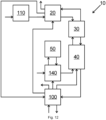
12 zwölftes beispielhafte Ausführungsform
-
1 first exemplary embodiment -
2 second exemplary embodiment -
3 third exemplary embodiment -
4 fourth exemplary embodiment -
5 fifth exemplary embodiment -
6 sixth exemplary embodiment -
7 seventh exemplary embodiment -
8th eighth exemplary embodiment -
9 ninth exemplary embodiment -
10 Tenth exemplary embodiment -
11 Eleventh exemplary embodiment -
12 Twelfth exemplary embodiment
Gleiche Bauteile sind im Folgenden mit gleichen Bezugszeichen versehen, um die Vergleichbarkeit über die verschiedenen Ausführungsformen zu vereinfachen.The same components are given the same reference numerals below in order to simplify comparability across the different embodiments.
In
Im Folgenden wird nur noch auf die Unterschiede der einzelnen Ausführungsformen eingegangen.Only the differences between the individual embodiments will be discussed below.
In
Die in
Die in
Die in
Die in
BezugszeichenReference symbols
- 1010
- AnlageAttachment
- 2020
- TrocknungsvorrichtungDrying device
- 3030
- VorwärmerPreheater
- 4040
- thermische Behandlungsvorrichtungthermal treatment device
- 5050
- erste Gasstromheizungfirst gas flow heater
- 6060
- WärmespeicherHeat storage
- 7070
- zweite Gasstromheizungsecond gas flow heater
- 8080
- dritte Gasstromheizungthird gas flow heater
- 100100
- MaterialkühlerMaterial cooler
- 110110
- Mühlemill
- 120120
- reduzierender Wirbelschichtreaktorreducing fluidized bed reactor
- 130130
- MaterialvorkühlerMaterial pre-cooler
- 140140
- Gas-Gas-WärmetauscherGas-gas heat exchanger
ZITATE ENTHALTEN IN DER BESCHREIBUNGQUOTES INCLUDED IN THE DESCRIPTION
Diese Liste der vom Anmelder aufgeführten Dokumente wurde automatisiert erzeugt und ist ausschließlich zur besseren Information des Lesers aufgenommen. Die Liste ist nicht Bestandteil der deutschen Patent- bzw. Gebrauchsmusteranmeldung. Das DPMA übernimmt keinerlei Haftung für etwaige Fehler oder Auslassungen.This list of documents listed by the applicant was generated automatically and is included solely for the better information of the reader. The list is not part of the German patent or utility model application. The DPMA assumes no liability for any errors or omissions.
Zitierte PatentliteraturCited patent literature
- WO 2022115721 A2 [0003]WO 2022115721 A2 [0003]
- DE 102014102474 A1 [0004, 0020]DE 102014102474 A1 [0004, 0020]
- DE 102021203071 [0005]DE 102021203071 [0005]
- DE 102021203072 [0005]DE 102021203072 [0005]
- DE 102021203073 [0005]DE 102021203073 [0005]
- DE 102021203074 [0005]DE 102021203074 [0005]
- DE 102020211750 A1 [0006, 0010, 0029, 0062]DE 102020211750 A1 [0006, 0010, 0029, 0062]
Claims (26)
Priority Applications (4)
| Application Number | Priority Date | Filing Date | Title |
|---|---|---|---|
| DE102022206778.9A DE102022206778A1 (en) | 2022-07-01 | 2022-07-01 | CO2-free production of artificial pozzolans, especially from clays |
| PCT/EP2023/067228 WO2024002927A1 (en) | 2022-07-01 | 2023-06-26 | Co2-free production of artificial pozzolans, in particular from clay |
| EP23735021.0A EP4548024A1 (en) | 2022-07-01 | 2023-06-26 | Co2-free production of artificial pozzolans, in particular from clay |
| CN202380051327.9A CN119546916A (en) | 2022-07-01 | 2023-06-26 | CO2-free production of artificial pozzolans, especially from clay |
Applications Claiming Priority (1)
| Application Number | Priority Date | Filing Date | Title |
|---|---|---|---|
| DE102022206778.9A DE102022206778A1 (en) | 2022-07-01 | 2022-07-01 | CO2-free production of artificial pozzolans, especially from clays |
Publications (1)
| Publication Number | Publication Date |
|---|---|
| DE102022206778A1 true DE102022206778A1 (en) | 2024-01-04 |
Family
ID=89167639
Family Applications (1)
| Application Number | Title | Priority Date | Filing Date |
|---|---|---|---|
| DE102022206778.9A Pending DE102022206778A1 (en) | 2022-07-01 | 2022-07-01 | CO2-free production of artificial pozzolans, especially from clays |
Country Status (1)
| Country | Link |
|---|---|
| DE (1) | DE102022206778A1 (en) |
Citations (7)
| Publication number | Priority date | Publication date | Assignee | Title |
|---|---|---|---|---|
| DE102014102474A1 (en) | 2014-02-25 | 2015-08-27 | Sandvik Materials Technology Deutschland Gmbh | Heating element and process heater |
| DE102020211750A1 (en) | 2020-09-21 | 2022-03-24 | Thyssenkrupp Ag | Energy recovery when cooling color-optimized activated clays |
| WO2022115721A2 (en) | 2020-11-30 | 2022-06-02 | Rondo Energy, Inc. | Energy storage system and applications |
| DE102021203073A1 (en) | 2021-03-26 | 2022-09-29 | Thyssenkrupp Ag | Device and method for the thermal treatment of a mineral starting material |
| DE102021203071A1 (en) | 2021-03-26 | 2022-09-29 | Thyssenkrupp Ag | Device and method for the thermal treatment of a mineral starting material |
| DE102021203074A1 (en) | 2021-03-26 | 2022-09-29 | Thyssenkrupp Ag | Process for the thermal treatment of a mineral starting material |
| DE102021203072A1 (en) | 2021-03-26 | 2022-09-29 | Thyssenkrupp Ag | Device and method for the thermal treatment of a mineral starting material |
-
2022
- 2022-07-01 DE DE102022206778.9A patent/DE102022206778A1/en active Pending
Patent Citations (7)
| Publication number | Priority date | Publication date | Assignee | Title |
|---|---|---|---|---|
| DE102014102474A1 (en) | 2014-02-25 | 2015-08-27 | Sandvik Materials Technology Deutschland Gmbh | Heating element and process heater |
| DE102020211750A1 (en) | 2020-09-21 | 2022-03-24 | Thyssenkrupp Ag | Energy recovery when cooling color-optimized activated clays |
| WO2022115721A2 (en) | 2020-11-30 | 2022-06-02 | Rondo Energy, Inc. | Energy storage system and applications |
| DE102021203073A1 (en) | 2021-03-26 | 2022-09-29 | Thyssenkrupp Ag | Device and method for the thermal treatment of a mineral starting material |
| DE102021203071A1 (en) | 2021-03-26 | 2022-09-29 | Thyssenkrupp Ag | Device and method for the thermal treatment of a mineral starting material |
| DE102021203074A1 (en) | 2021-03-26 | 2022-09-29 | Thyssenkrupp Ag | Process for the thermal treatment of a mineral starting material |
| DE102021203072A1 (en) | 2021-03-26 | 2022-09-29 | Thyssenkrupp Ag | Device and method for the thermal treatment of a mineral starting material |
Similar Documents
| Publication | Publication Date | Title |
|---|---|---|
| DE68919380T2 (en) | Process for converting fuel into electricity. | |
| EP2346600A2 (en) | Energy-efficient system for generating carbon black, preferably in energetic cooperation with systems for generating silicon dioxide and/or silicon | |
| CH626751A5 (en) | ||
| DE102020201068A1 (en) | System with thermal energy storage, procedures for operation and procedures for modification | |
| DE102016015012A1 (en) | Process for heat recovery from a flue gas produced by a burner | |
| DE102014203039A1 (en) | Method and device for separating exhaust gas during the combustion of certain metals | |
| DE102017205020A1 (en) | Reaction device with heat exchanger and their use | |
| DE102018132736A1 (en) | Process and plant for producing one or more gaseous reaction products in a fired reactor | |
| WO2011020767A1 (en) | Method and device for utilizing biomass | |
| EP0361612B1 (en) | Method for generating electricity | |
| DE102009038322A1 (en) | Method and apparatus for converting thermal energy from biomass to mechanical work | |
| DD201698A5 (en) | METHOD AND DEVICE FOR REDUCING OIL TO SPONGE METALS WITH ONE GAS | |
| BE1030687B1 (en) | CO2-free production of artificial pozzolans, especially from clays | |
| DE2400772C3 (en) | ||
| DE102022206778A1 (en) | CO2-free production of artificial pozzolans, especially from clays | |
| EP4548024A1 (en) | Co2-free production of artificial pozzolans, in particular from clay | |
| EP2784288B1 (en) | Power plant and method for generating electric power | |
| EP3859207B1 (en) | Combustion installation with heat accumulator | |
| DE102022118858A1 (en) | Thermal cracking of methane or natural gas | |
| DE2821413C2 (en) | ||
| EP3002250B1 (en) | Power plant and method for operating same | |
| AT406165B (en) | DEVICE FOR CONTINUOUS DISTILLATIVE SEPARATION OF RAW OIL | |
| DE102019111827B4 (en) | Method for operating a pyrolysis plant and pyrolysis plant | |
| DE102023103471A1 (en) | Optimized heat management in a plant for the thermal treatment of mineral substances | |
| EP3002325B1 (en) | Power plant and method for generating electric power |
Legal Events
| Date | Code | Title | Description |
|---|---|---|---|
| R081 | Change of applicant/patentee |
Owner name: THYSSENKRUPP POLYSIUS GMBH, DE Free format text: FORMER OWNERS: THYSSENKRUPP AG, 45143 ESSEN, DE; THYSSENKRUPP INDUSTRIAL SOLUTIONS AG, 45143 ESSEN, DE Owner name: THYSSENKRUPP AG, DE Free format text: FORMER OWNERS: THYSSENKRUPP AG, 45143 ESSEN, DE; THYSSENKRUPP INDUSTRIAL SOLUTIONS AG, 45143 ESSEN, DE |