DE102022129101A1 - Battery system and motor vehicle - Google Patents
Battery system and motor vehicle Download PDFInfo
- Publication number
- DE102022129101A1 DE102022129101A1 DE102022129101.4A DE102022129101A DE102022129101A1 DE 102022129101 A1 DE102022129101 A1 DE 102022129101A1 DE 102022129101 A DE102022129101 A DE 102022129101A DE 102022129101 A1 DE102022129101 A1 DE 102022129101A1
- Authority
- DE
- Germany
- Prior art keywords
- battery system
- enclosure
- battery
- fluid
- enclosures
- Prior art date
- Legal status (The legal status is an assumption and is not a legal conclusion. Google has not performed a legal analysis and makes no representation as to the accuracy of the status listed.)
- Pending
Links
Images

Classifications
-
- H—ELECTRICITY
- H01—ELECTRIC ELEMENTS
- H01M—PROCESSES OR MEANS, e.g. BATTERIES, FOR THE DIRECT CONVERSION OF CHEMICAL ENERGY INTO ELECTRICAL ENERGY
- H01M50/00—Constructional details or processes of manufacture of the non-active parts of electrochemical cells other than fuel cells, e.g. hybrid cells
- H01M50/10—Primary casings; Jackets or wrappings
- H01M50/14—Primary casings; Jackets or wrappings for protecting against damage caused by external factors
- H01M50/143—Fireproof; Explosion-proof
-
- H—ELECTRICITY
- H01—ELECTRIC ELEMENTS
- H01M—PROCESSES OR MEANS, e.g. BATTERIES, FOR THE DIRECT CONVERSION OF CHEMICAL ENERGY INTO ELECTRICAL ENERGY
- H01M50/00—Constructional details or processes of manufacture of the non-active parts of electrochemical cells other than fuel cells, e.g. hybrid cells
- H01M50/20—Mountings; Secondary casings or frames; Racks, modules or packs; Suspension devices; Shock absorbers; Transport or carrying devices; Holders
- H01M50/218—Mountings; Secondary casings or frames; Racks, modules or packs; Suspension devices; Shock absorbers; Transport or carrying devices; Holders characterised by the material
-
- H—ELECTRICITY
- H01—ELECTRIC ELEMENTS
- H01M—PROCESSES OR MEANS, e.g. BATTERIES, FOR THE DIRECT CONVERSION OF CHEMICAL ENERGY INTO ELECTRICAL ENERGY
- H01M50/00—Constructional details or processes of manufacture of the non-active parts of electrochemical cells other than fuel cells, e.g. hybrid cells
- H01M50/20—Mountings; Secondary casings or frames; Racks, modules or packs; Suspension devices; Shock absorbers; Transport or carrying devices; Holders
- H01M50/233—Mountings; Secondary casings or frames; Racks, modules or packs; Suspension devices; Shock absorbers; Transport or carrying devices; Holders characterised by physical properties of casings or racks, e.g. dimensions
-
- H—ELECTRICITY
- H01—ELECTRIC ELEMENTS
- H01M—PROCESSES OR MEANS, e.g. BATTERIES, FOR THE DIRECT CONVERSION OF CHEMICAL ENERGY INTO ELECTRICAL ENERGY
- H01M50/00—Constructional details or processes of manufacture of the non-active parts of electrochemical cells other than fuel cells, e.g. hybrid cells
- H01M50/30—Arrangements for facilitating escape of gases
- H01M50/35—Gas exhaust passages comprising elongated, tortuous or labyrinth-shaped exhaust passages
- H01M50/358—External gas exhaust passages located on the battery cover or case
-
- H—ELECTRICITY
- H01—ELECTRIC ELEMENTS
- H01M—PROCESSES OR MEANS, e.g. BATTERIES, FOR THE DIRECT CONVERSION OF CHEMICAL ENERGY INTO ELECTRICAL ENERGY
- H01M50/00—Constructional details or processes of manufacture of the non-active parts of electrochemical cells other than fuel cells, e.g. hybrid cells
- H01M50/60—Arrangements or processes for filling or topping-up with liquids; Arrangements or processes for draining liquids from casings
- H01M50/673—Containers for storing liquids; Delivery conduits therefor
- H01M50/682—Containers for storing liquids; Delivery conduits therefor accommodated in battery or cell casings
-
- H—ELECTRICITY
- H01—ELECTRIC ELEMENTS
- H01M—PROCESSES OR MEANS, e.g. BATTERIES, FOR THE DIRECT CONVERSION OF CHEMICAL ENERGY INTO ELECTRICAL ENERGY
- H01M50/00—Constructional details or processes of manufacture of the non-active parts of electrochemical cells other than fuel cells, e.g. hybrid cells
- H01M50/60—Arrangements or processes for filling or topping-up with liquids; Arrangements or processes for draining liquids from casings
- H01M50/691—Arrangements or processes for draining liquids from casings; Cleaning battery or cell casings
-
- H—ELECTRICITY
- H01—ELECTRIC ELEMENTS
- H01M—PROCESSES OR MEANS, e.g. BATTERIES, FOR THE DIRECT CONVERSION OF CHEMICAL ENERGY INTO ELECTRICAL ENERGY
- H01M2220/00—Batteries for particular applications
- H01M2220/20—Batteries in motive systems, e.g. vehicle, ship, plane
Landscapes
- Chemical & Material Sciences (AREA)
- Chemical Kinetics & Catalysis (AREA)
- Electrochemistry (AREA)
- General Chemical & Material Sciences (AREA)
- Battery Mounting, Suspending (AREA)
Abstract
Ein Batteriesystem mit Batteriezellen (10) und mit einer Mehrzahl von Umschließungen (12), mit Fluidauslass (20) an jeder Umschließung und einem Fluidabfuhrkanal (22) erhält einen besonderen Brandschutz durch Verwendung von feuerfesten Wandungen für die Umschließungen (12) und/oder durch ein Einstecken der Fluidauslässe in einen Stutzen (26) des Kanals.
Description
Die Erfindung betrifft ein Batteriesystem, insbesondere für ein Kraftfahrzeug. Die Erfindung betrifft auch ein Kraftfahrzeug mit diesem Batteriesystem. Es geht insbesondere um die Batterien, die einen elektrischen Antriebsmotor des Kraftfahrzeugs speisen.The invention relates to a battery system, in particular for a motor vehicle. The invention also relates to a motor vehicle with this battery system. It particularly concerns the batteries that feed an electric drive motor of the motor vehicle.
Ein solches Batteriesystem umfasst eine Mehrzahl von Batteriezellen. Gegenwärtig enthalten typische Batteriezellen Lithium.Such a battery system comprises a plurality of battery cells. Currently, typical battery cells contain lithium.
Aus der
Mit dem Thema, Bränden vorzubeugen, befasst sich auch die
Es ist Aufgabe der Erfindung, den Schutz vor einem Abbrennen eines Batteriesystems und damit des Kraftfahrzeugs zu erhöhen.The object of the invention is to increase the protection against a battery system and thus the motor vehicle burning out.
Die Aufgabe wird in einem Aspekt durch ein Batteriesystem gemäß Patentanspruch 1 und in einem anderen Aspekt durch ein Batteriesystem gemäß Patentanspruch 6 gelöst. Zur Erfindung gehört auch das Bereitstellen eines Kraftfahrzeugs mit einem solchen Batteriesystem.The object is achieved in one aspect by a battery system according to patent claim 1 and in another aspect by a battery system according to patent claim 6. The invention also includes the provision of a motor vehicle with such a battery system.
Das Batteriesystem umfasst gemäß dem ersten Aspekt Batteriezellen und eine Mehrzahl von Umschließungen, die jeweils zumindest eine der Batteriezellen zumindest abschnittsweise, vorzugsweise vollständig, umschließen, und die jeweils zumindest einen Fluidauslass aufweisen, wobei mehrere Fluidauslässe unterschiedlicher Umschließungen an einen Fluidabfuhrkanal gekoppelt sind, wobei erfindungsgemäß eine Wandung der Umschließungen feuerfest ist.According to the first aspect, the battery system comprises battery cells and a plurality of enclosures, each of which encloses at least one of the battery cells at least partially, preferably completely, and each of which has at least one fluid outlet, wherein a plurality of fluid outlets of different enclosures are coupled to a fluid discharge channel, wherein according to the invention a wall of the enclosures is fireproof.
Aufgrund der feuerfesten Ausbildung der Wandungen der Umschließungen wird ein Überspringen des Brandes einer Batteriezelle vermieden. Somit kann es zwar - in einem immer noch unwahrscheinlichen Fall - dazu kommen, dass sich eine Batteriezelle aufgrund von Widrigkeiten entzündet, in diesem Fall bleibt der Brand aber lokal, im Wesentlichen innerhalb der jeweiligen Umschließung, und das Kraftfahrzeug brennt nicht als Ganzes ab.The fireproof design of the enclosure walls prevents the fire from spreading to a battery cell. This means that although it is still unlikely that a battery cell will ignite due to adverse conditions, the fire will remain local, essentially within the enclosure, and the vehicle will not burn down as a whole.
Das Merkmal „feuerfest“ lässt sich insbesondere so definieren, dass die Wandungen der Umschließungen aus einem solchen Material und in einer solchen Wandstärke gebildet sind, dass ihre Temperatur bei einem Brand der in der jeweiligen Umschließung enthaltenen Batteriezellen unterhalb derjenigen Temperatur bleibt, bei der sich eine Batteriezelle in einer der jeweiligen Umschließung benachbarten Umschließung entzünden würde. Durch wenige Versuche und gegebenenfalls Berechnungen lässt sich bei vorgegebenem Material eine möglichst geringe Wandstärke, die dieses Merkmal immer noch erfüllt, wählen. Dies sorgt für eine Gewichtsoptimierung bei bleibendem Schutz vor einem Abbrennen des Kraftfahrzeugs.The feature "fireproof" can be defined in particular in such a way that the walls of the enclosures are made of such a material and with such a wall thickness that, in the event of a fire in the battery cells contained in the respective enclosure, their temperature remains below the temperature at which a battery cell in an enclosure adjacent to the respective enclosure would ignite. With a few tests and, if necessary, calculations, the smallest possible wall thickness can be selected for a given material that still meets this feature. This ensures weight optimization while maintaining protection against the vehicle burning down.
Eine Batteriezelle kann eine Temperatur von bis über 800°C, ja sogar über 1000°C, erzeugen. Vorzugsweise sind somit die Wandungen bezüglich einer Temperatur von 800°C, vorzugsweise von 1000°C, weiter vorzugsweise von 1200°C, in der Umschließung feuerfest ausgelegt.A battery cell can generate a temperature of up to over 800°C, even over 1000°C. Preferably, the walls in the enclosure are therefore designed to be fireproof with respect to a temperature of 800°C, preferably 1000°C, more preferably 1200°C.
Es lassen sich mit diesen Vorgaben Materialien und Wandstärken wählen.Materials and wall thicknesses can be selected using these specifications.
Ein Material der Wahl kann eine Metalllegierung umfassen, wobei sich etwa Stahlblech wegen seiner guten Biegbarkeit und generellen guten Verarbeitbarkeit in besonderem Maße eignet.A material of choice can include a metal alloy, with sheet steel being particularly suitable due to its good bendability and generally good processability.
Der zweite Aspekt - auch in der Rolle als bevorzugte Ausführungsform des ersten Aspekts - beinhaltet, dass bei dem Batteriesystem gemäß dem Oberbegriff der unabhängigen Patentansprüche 1 und 6 der Fluidauslass durch ein Auslassrohr bereitgestellt ist, wobei erfindungsgemäß das Auslassrohr in einen zum Fluidabfuhrkanal zugehörigen Stutzen eingesteckt ist, vorzugsweise dichtend eingepasst ist.The second aspect - also in the role as a preferred embodiment of the first aspect - includes that in the battery system according to the preamble of independent patent claims 1 and 6, the fluid outlet is provided by an outlet pipe, wherein according to the invention the outlet pipe is inserted into a nozzle associated with the fluid discharge channel, preferably fitted in a sealing manner.
Dies unterscheidet sich von der festen Kopplung der Rohre der
Prinzipiell ist die Steckkopplung als Schiebesitz verwirklichbar. Die Gasführung wird hierbei etwa durch Ineinanderstecken von Innenhochdruck-Umformteilen ermöglicht.In principle, the plug-in coupling can be implemented as a sliding seat. The gas flow is made possible by inserting internal high-pressure formed parts into one another.
Bevorzugt allerdings lässt sich dieser Aspekt so verwirklichen, dass das Auslassrohr mittels eines temperaturbeständigen Dichtsystems in den Fluidabfuhrkanal eingedichtet ist, etwa unter Einsatz eines Drahtgestricks.Preferably, however, this aspect can be realized in such a way that the outlet pipe is sealed into the fluid discharge channel by means of a temperature-resistant sealing system, for example by using a wire mesh.
Gemäß einer bevorzugten Ausführungsform zu beiden Aspekten ist die Umschließung als Aufsatzkörper ausgebildet oder umfasst einen solchen, der durch einen feuerfesten Boden des Batteriesystems oder einen feuerfesten Deckel des Batteriesystems oder einen feuerfesten Deckel der Umschließung abgeschlossen ist. Auf diese Weise lässt sich das Batteriesystem leicht zusammensetzen, indem der Aufsatzkörper, welchen man mit seinem zugehörigen Auslassrohr als „trichterförmig“ bezeichnen kann, einfach auf die Batteriezellen aufgesetzt wird. Der Fluidabfuhrkanal lässt sich so insbesondere seinerseits leicht aufsetzen. Dies gilt insbesondere, wenn ein Drahtgestrick bereits auf die Auslassrohre aufgebracht sind. Die Herstellung des Batteriesystems ist daher auch leichter als etwa bei festen Kopplungen von Umschließung und Fluidabfuhrkanal.According to a preferred embodiment of both aspects, the enclosure is designed as an attachment body or comprises one which is closed off by a fireproof base of the battery system or a fireproof cover of the battery system or a fireproof cover of the enclosure. In this way, the battery system can be easily assembled by simply placing the attachment body, which can be described as "funnel-shaped" with its associated outlet pipe, on the battery cells. The fluid discharge channel can thus be easily placed on itself. This is especially true if a wire mesh has already been applied to the outlet pipes. The battery system is therefore also easier to manufacture than, for example, with fixed couplings of the enclosure and the fluid discharge channel.
Gemäß einem weiteren bevorzugten Aspekt der Erfindung umfasst jede Umschließung einen Leerraum als Fluidpuffer. Wenn insbesondere das entstehende Gas zunächst in dem Leerraum gespeichert wird, bevor es über den Fluidabfuhrkanal abgeführt wird, erhitzt sich der Fluidabfuhrkanal weniger schnell, und auch dieser Aspekt sorgt dafür, dass ein Brand nicht ohne Weiteres überspringen kann.According to a further preferred aspect of the invention, each enclosure comprises an empty space as a fluid buffer. If in particular the gas that is produced is initially stored in the empty space before it is discharged via the fluid discharge channel, the fluid discharge channel heats up less quickly, and this aspect also ensures that a fire cannot easily spread.
Das erfindungsgemäße Kraftfahrzeug weist ein Batteriesystem gemäß der Erfindung auf. Naturgemäß umfasst es typischerweise einen elektrischen Antriebsmotor, der mittels des Batteriesystems gespeist wird.The motor vehicle according to the invention has a battery system according to the invention. Naturally, it typically comprises an electric drive motor that is powered by the battery system.
Insgesamt somit wird durch die Erfindung vermieden, dass eine heftige exotherme Reaktion einer sich entzündenden (kritischen) Batteriezelle zu massiven Beschädigungen innerhalb des gesamten Batteriesystems führt. Stattdessen bleibt die exotherme Reaktion auf eine Batteriezelle beschränkt und ist damit beherrschbar. Das Kraftfahrzeug kann nicht mehr abbrennen.Overall, the invention prevents a violent exothermic reaction of an igniting (critical) battery cell from causing massive damage to the entire battery system. Instead, the exothermic reaction remains limited to one battery cell and is therefore manageable. The vehicle can no longer burn down.
Für Anwendungsfälle oder Anwendungssituationen, die sich bei dem Verfahren zum Schützen vor einem Brand ergeben können und die hier nicht explizit beschrieben sind, kann vorgesehen sein, dass gemäß dem Verfahren eine Fehlermeldung und/oder eine Aufforderung zur Eingabe einer Nutzerrückmeldung ausgegeben und/oder eine Standardeinstellung und/oder ein vorbestimmter Initialzustand eingestellt wird.For use cases or application situations that may arise in the method for protecting against fire and which are not explicitly described here, it may be provided that, in accordance with the method, an error message and/or a request to enter user feedback is issued and/or a default setting and/or a predetermined initial state is set.
Zu der Erfindung gehört auch die Steuervorrichtung für das Kraftfahrzeug. Die Steuervorrichtung kann eine Datenverarbeitungsvorrichtung oder eine Prozessoreinrichtung aufweisen, die dazu eingerichtet ist, eine Ausführungsform des erfindungsgemäßen Verfahrens durchzuführen. Die Prozessoreinrichtung kann hierzu zumindest einen Mikroprozessor und/oder zumindest einen Mikrocontroller und/oder zumindest einen FPGA (Field Programmable Gate Array) und/oder zumindest einen DSP (Digital Signal Processor) aufweisen. Des Weiteren kann die Prozessoreinrichtung Programmcode aufweisen, der dazu eingerichtet ist, bei Ausführen durch die Prozessoreinrichtung die Ausführungsform des erfindungsgemäßen Verfahrens durchzuführen. Der Programmcode kann in einem Datenspeicher der Prozessoreinrichtung gespeichert sein. Eine Prozessorschaltung der Prozessoreinrichtung kann z.B. zumindest eine Schaltungsplatine und/oder zumindest ein SoC (System on Chip) aufweisen.The invention also includes the control device for the motor vehicle. The control device can have a data processing device or a processor device that is set up to carry out an embodiment of the method according to the invention. For this purpose, the processor device can have at least one microprocessor and/or at least one microcontroller and/or at least one FPGA (Field Programmable Gate Array) and/or at least one DSP (Digital Signal Processor). Furthermore, the processor device can have program code that is set up to carry out the embodiment of the method according to the invention when executed by the processor device. The program code can be stored in a data memory of the processor device. A processor circuit of the processor device can, for example, have at least one circuit board and/or at least one SoC (System on Chip).
Zu der Erfindung gehören auch Weiterbildungen des durchgeführten Verfahrens, die Merkmale aufweisen, wie sie bereits im Zusammenhang mit den Weiterbildungen des erfindungsgemäßen Kraftfahrzeugs beschrieben worden sind. Aus diesem Grund sind die entsprechenden Weiterbildungen des erfindungsgemäßen Verfahrens hier nicht noch einmal beschrieben. The invention also includes further developments of the method carried out, which have features as have already been described in connection with the further developments of the motor vehicle according to the invention. For this reason, the corresponding further developments of the method according to the invention are not described again here.
Das erfindungsgemäße Kraftfahrzeug ist bevorzugt als Kraftwagen, insbesondere als Personenkraftwagen oder Lastkraftwagen, oder als Personenbus oder Motorrad ausgestaltet.The motor vehicle according to the invention is preferably designed as a motor vehicle, in particular as a passenger car or truck, or as a passenger bus or motorcycle.
Die Erfindung umfasst auch die Kombinationen der Merkmale der beschriebenen Ausführungsformen. Die Erfindung umfasst also auch Realisierungen, die jeweils eine Kombination der Merkmale mehrerer der beschriebenen Ausführungsformen aufweisen, sofern die Ausführungsformen nicht als sich gegenseitig ausschließend beschrieben wurden.The invention also includes combinations of the features of the described embodiments. The invention therefore also includes implementations that each comprise a combination of the features of several of the described embodiments unless the embodiments are described as mutually exclusive.
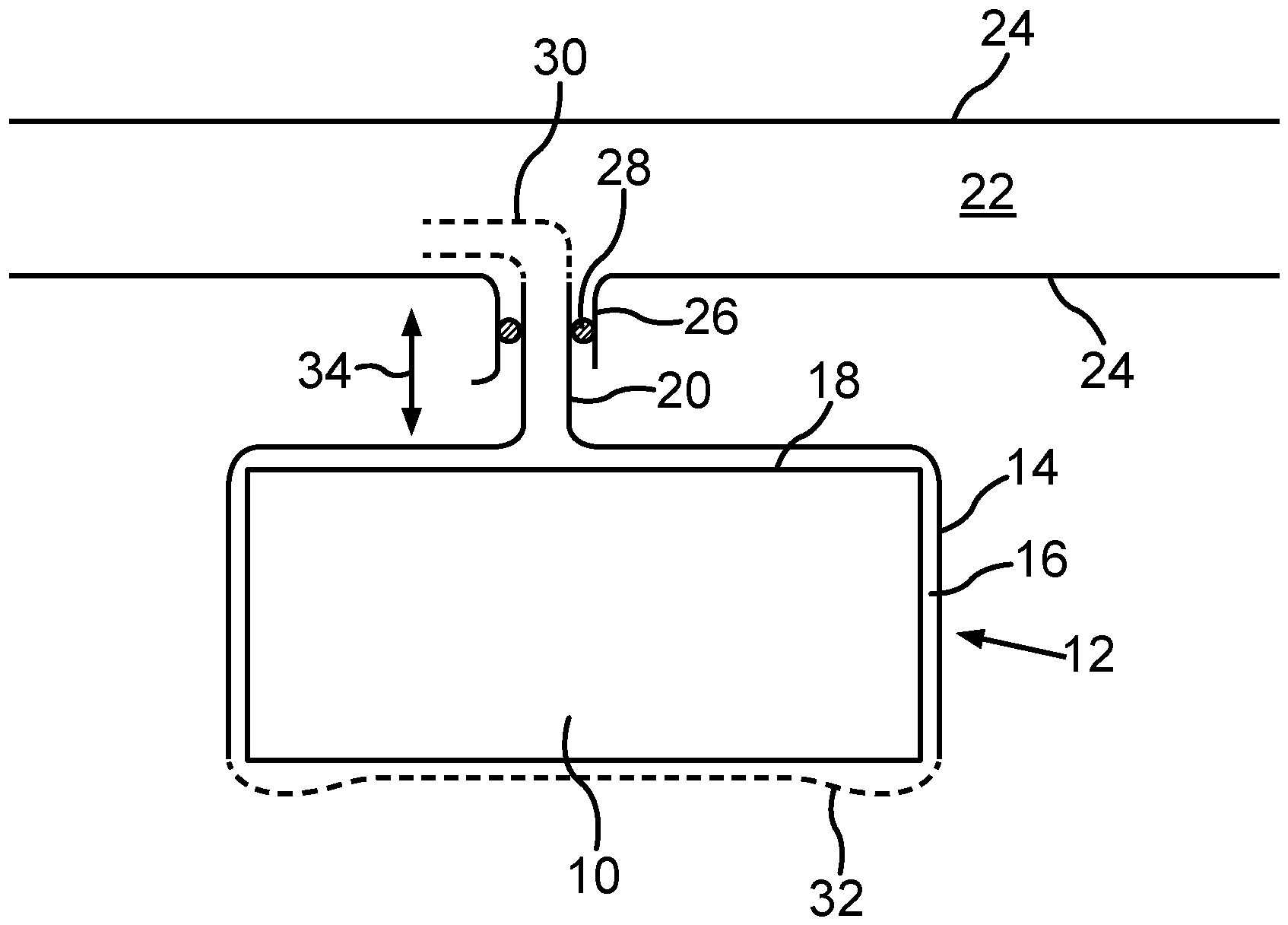
Im Folgenden sind Ausführungsbeispiele der Erfindung beschrieben. Hierzu zeigt:
-
1 einen Ausschnitt aus einem erfindungsgemäßen Batteriesystem, darstellend eine einzelne Umschließung mit einer einzelnen Batteriezelle.
-
1 a section of a battery system according to the invention, showing a single enclosure with a single battery cell.
Bei den im Folgenden erläuterten Ausführungsbeispielen handelt es sich um bevorzugte Ausführungsformen der Erfindung. Bei den Ausführungsbeispielen stellen die beschriebenen Komponenten der Ausführungsformen jeweils einzelne, unabhängig voneinander zu betrachtende Merkmale der Erfindung dar, welche die Erfindung jeweils auch unabhängig voneinander weiterbilden. Daher soll die Offenbarung auch andere als die dargestellten Kombinationen der Merkmale der Ausführungsformen umfassen. Des Weiteren sind die beschriebenen Ausführungsformen auch durch weitere der bereits beschriebenen Merkmale der Erfindung ergänzbar.The exemplary embodiments explained below are preferred embodiments of the invention. In the exemplary embodiments, the components of the embodiments described each represent individual features of the invention that are to be considered independently of one another and which also develop the invention independently of one another. Therefore, the disclosure should also include combinations of the features of the embodiments other than those shown. Furthermore, the described embodiments can also be supplemented by other features of the invention already described.
Eine im Ganzen mit 10 bezeichnete Batteriezelle eines Batteriesystems, das mehrere solche Batteriezellen aufweist, ist von einer trichterförmigen Umschließung 12 bedeckt, die aus Edelstahl besteht und beispielsweise eine Wanddicke von mindestens 0,3 cm, vorzugsweise von mindestens 0,5 cm, aufweist. Die Umschließung 12 umfasst einen Aufsatzkörper 14, der im Wesentlichen die Form der Batteriezelle 10 nachbildet, allerdings zusätzlich neben und/oder über der Batteriezelle Leerräume 16 bzw. 18 bereitstellt, die als Pufferräume für Gas dienen. Vom Aufsatzkörper 14 erstreckt sich ein Auslassrohr 20. Dieses ist mit einem Entgasungskanal (Fluidabfuhrkanal) 22 gekoppelt, der durch Wandungen 24 begrenzt ist. Der Fluidabfuhrkanal lässt sich auch nach dem in Batteriezellen entstehenden sogenannten „Ventgas“ als „Ventkanal“ bezeichnen. Vorliegend von Bedeutung ist es, dass das Auslassrohr 20 in einem Einlassstutzen 26 am Fluidabfuhrkanal 24 eingeführt ist und dort mittels eines Dichtsystems, insbesondere in Form eines radial angordneten Drahtgestricks 28 abgedichtet ist. Wie durch die Strichlierung gemäß 30 gezeigt, kann sich das Auslassrohr optional in den Fluidabfuhrkanal 22 in eine Richtung hinein (gekrümmt) erstrecken, um so eine Abfuhrrichtung für das Ventgas vorzugeben. Die Batteriezelle kann auf einem Boden 32 stehen, der Teil des Batteriesystems oder etwa nur Teil einer Fahrzeugkarosserie ist. Es kann dort jedoch ein gesonderter Deckel vorgesehen sein, wobei es sich entweder um einen Deckel für das gesamte Batteriesystem handeln kann, oder um einen Deckel, der lediglich die einzelne Batteriezelle abdeckt und damit den Aufsatzkörper 14 abschließt.A battery cell, designated as a whole by 10, of a battery system that has several such battery cells is covered by a funnel-shaped
Insgesamt also ist in dem Ausführungsbeispiel jede Batteriezelle von einer trichterförmigen Umschließung oder Hülle umgeben, welche die Batteriezelle 10 gasdicht abschließt. Selbst, wenn sich eine Batteriezelle entzünden sollte, wird das entstehende Ventgas durch das Auslassrohr 20 in den Fluidabfuhrkanal 22 geleitet. Es kann gegebenenfalls mehrere „Kamine“ (Auslassrohre) für eine Umschließung geben. Die Umschließung ist feuerfest, so dass sie auch unter der Reaktion und des Abbrennens der betreffenden Batteriezelle 10 ihre Funktion eines Schutzes beibehält. Durch das Verwenden der radialen Dichtung 28 ist die Abdichtwirkung auch bei thermischer Dehnung der Vorrichtung und damit insbesondere auch des Auslassrohres 20 weiterhin gegeben. (Bei etwa einer thermischen Ausdehnung gemäß dem Pfeil 34 in Längserstreckung des Auslassrohres 20.) Durch die feuerfeste Umschließung 12 als zusätzlicher Materialschicht und dadurch entstehenden weiteren Kontaktwärmeübergängen kommt es zu einer weiteren Isolation der kritischen Batteriezelle.Overall, in the exemplary embodiment, each battery cell is surrounded by a funnel-shaped enclosure or casing which seals the
Insgesamt zeigt das Beispiel, wie eine kontrollierte Führung des Ventgases im Batteriemodul zur Verhinderung von Thermal-Propagation bereitgestellt werden kann.Overall, the example shows how a controlled guidance of the vent gas in the battery module can be provided to prevent thermal propagation.
ZITATE ENTHALTEN IN DER BESCHREIBUNGQUOTES INCLUDED IN THE DESCRIPTION
Diese Liste der vom Anmelder aufgeführten Dokumente wurde automatisiert erzeugt und ist ausschließlich zur besseren Information des Lesers aufgenommen. Die Liste ist nicht Bestandteil der deutschen Patent- bzw. Gebrauchsmusteranmeldung. Das DPMA übernimmt keinerlei Haftung für etwaige Fehler oder Auslassungen.This list of documents listed by the applicant was generated automatically and is included solely for the better information of the reader. The list is not part of the German patent or utility model application. The DPMA accepts no liability for any errors or omissions.
Zitierte PatentliteraturCited patent literature
- DE 102013210323 A1 [0003, 0014]DE 102013210323 A1 [0003, 0014]
- WO 2016010722 A1 [0004]WO 2016010722 A1 [0004]
- CN 216133908 U [0004]CN 216133908 U [0004]
Claims (10)
Priority Applications (1)
| Application Number | Priority Date | Filing Date | Title |
|---|---|---|---|
| DE102022129101.4A DE102022129101A1 (en) | 2022-11-03 | 2022-11-03 | Battery system and motor vehicle |
Applications Claiming Priority (1)
| Application Number | Priority Date | Filing Date | Title |
|---|---|---|---|
| DE102022129101.4A DE102022129101A1 (en) | 2022-11-03 | 2022-11-03 | Battery system and motor vehicle |
Publications (1)
| Publication Number | Publication Date |
|---|---|
| DE102022129101A1 true DE102022129101A1 (en) | 2024-05-08 |
Family
ID=90732075
Family Applications (1)
| Application Number | Title | Priority Date | Filing Date |
|---|---|---|---|
| DE102022129101.4A Pending DE102022129101A1 (en) | 2022-11-03 | 2022-11-03 | Battery system and motor vehicle |
Country Status (1)
| Country | Link |
|---|---|
| DE (1) | DE102022129101A1 (en) |
Citations (10)
| Publication number | Priority date | Publication date | Assignee | Title |
|---|---|---|---|---|
| US20070218351A1 (en) | 2006-03-17 | 2007-09-20 | Boerner Russell W | Battery system with gas discharge device |
| JP2009289583A (en) | 2008-05-29 | 2009-12-10 | Kojima Press Industry Co Ltd | Smoke discharge tube |
| JP2012204193A (en) | 2011-03-25 | 2012-10-22 | Mitsubishi Heavy Ind Ltd | Battery pack |
| DE102012200869A1 (en) | 2012-01-23 | 2013-07-25 | Robert Bosch Gmbh | Battery and motor vehicle |
| DE102013210323A1 (en) | 2013-06-04 | 2014-12-04 | Robert Bosch Gmbh | Battery system and vehicle with battery system |
| US20150325827A1 (en) | 2014-05-06 | 2015-11-12 | Airbus Operations Gmbh | Aircraft battery exhaust system |
| WO2016010722A1 (en) | 2014-07-14 | 2016-01-21 | The Chemours Company Fc, Llc | Li-ion battery having improved safety against combustion |
| WO2022008080A1 (en) | 2020-07-10 | 2022-01-13 | Polarium Energy Solutions Ab | Battery device |
| CN216133908U (en) | 2021-08-03 | 2022-03-25 | 陕西奥林波斯电力能源有限责任公司 | Battery box safety structure for lithium battery |
| DE102021200383A1 (en) | 2021-01-18 | 2022-07-21 | Volkswagen Aktiengesellschaft | Battery and vehicle with such |
-
2022
- 2022-11-03 DE DE102022129101.4A patent/DE102022129101A1/en active Pending
Patent Citations (10)
| Publication number | Priority date | Publication date | Assignee | Title |
|---|---|---|---|---|
| US20070218351A1 (en) | 2006-03-17 | 2007-09-20 | Boerner Russell W | Battery system with gas discharge device |
| JP2009289583A (en) | 2008-05-29 | 2009-12-10 | Kojima Press Industry Co Ltd | Smoke discharge tube |
| JP2012204193A (en) | 2011-03-25 | 2012-10-22 | Mitsubishi Heavy Ind Ltd | Battery pack |
| DE102012200869A1 (en) | 2012-01-23 | 2013-07-25 | Robert Bosch Gmbh | Battery and motor vehicle |
| DE102013210323A1 (en) | 2013-06-04 | 2014-12-04 | Robert Bosch Gmbh | Battery system and vehicle with battery system |
| US20150325827A1 (en) | 2014-05-06 | 2015-11-12 | Airbus Operations Gmbh | Aircraft battery exhaust system |
| WO2016010722A1 (en) | 2014-07-14 | 2016-01-21 | The Chemours Company Fc, Llc | Li-ion battery having improved safety against combustion |
| WO2022008080A1 (en) | 2020-07-10 | 2022-01-13 | Polarium Energy Solutions Ab | Battery device |
| DE102021200383A1 (en) | 2021-01-18 | 2022-07-21 | Volkswagen Aktiengesellschaft | Battery and vehicle with such |
| CN216133908U (en) | 2021-08-03 | 2022-03-25 | 陕西奥林波斯电力能源有限责任公司 | Battery box safety structure for lithium battery |
Similar Documents
| Publication | Publication Date | Title |
|---|---|---|
| EP3493293B1 (en) | Insulating facing for housing | |
| EP1371121B1 (en) | Electrical installation comprising a decompression channel | |
| DE102021114113A1 (en) | BATTERY UNIT, BATTERY MODULE AND BATTERY PACK | |
| DE102013216071A1 (en) | Galvanic system comprising a plurality of galvanic cells and a degassing device | |
| DE102018202947A1 (en) | Protective device for a motor vehicle battery housing, traction battery and motor vehicle | |
| WO2019243079A1 (en) | Vehicle with a high-voltage accumulator | |
| EP3644402B1 (en) | Battery housing comprising a valve for pressure compensation and/or dissipation | |
| DE202009019120U1 (en) | Heat protection for temperature-sensitive components | |
| DE102021102523A1 (en) | BATTERY PACK SUB-UNIT AND BATTERY MODULE INCLUDE THIS | |
| DE102014003586A1 (en) | Fuel tank, motor vehicle | |
| DE102019209210A1 (en) | Fuel cell system with a ventilation line and / or a compressor ventilation line, method for ventilating a housing of a fuel cell system and motor vehicle | |
| DE102022129101A1 (en) | Battery system and motor vehicle | |
| DE102021100727A1 (en) | Electrical energy storage | |
| DE102020125651A1 (en) | Cooling device for a battery cell arrangement | |
| DE102018202742B4 (en) | Pressure tank for an automobile and an automobile | |
| DE112017007420T5 (en) | Valve and exhaust system with such a valve | |
| DE102018209195A1 (en) | Energy storage for a motor vehicle, motor vehicle and method for producing such energy storage | |
| WO2020011472A1 (en) | High-voltage accumulator for vehicles | |
| DE102024128808A1 (en) | One-way valve for battery cells | |
| DE2625357C3 (en) | Nuclear reactor in a refrigerated safety envelope enclosing it | |
| DE102019100889A1 (en) | High voltage storage and vehicle with a high voltage storage | |
| DE102005062030B3 (en) | Heat shield for mounting on a heat-radiating article, in particular on a rocket engine | |
| DE202022104795U1 (en) | Control cabinet and elements for a control cabinet | |
| DE102022115265B4 (en) | BATTERY RECORDING SYSTEM | |
| DE102025115401A1 (en) | Pressure relief device for a battery housing, a battery case and a vehicle battery |
Legal Events
| Date | Code | Title | Description |
|---|---|---|---|
| R163 | Identified publications notified |