DE102022114502B4 - Gripping device for gripping during the manufacture of a bipolar plate - Google Patents
Gripping device for gripping during the manufacture of a bipolar plate Download PDFInfo
- Publication number
- DE102022114502B4 DE102022114502B4 DE102022114502.6A DE102022114502A DE102022114502B4 DE 102022114502 B4 DE102022114502 B4 DE 102022114502B4 DE 102022114502 A DE102022114502 A DE 102022114502A DE 102022114502 B4 DE102022114502 B4 DE 102022114502B4
- Authority
- DE
- Germany
- Prior art keywords
- engagement
- sheet
- gripping
- pins
- engagement pin
- Prior art date
- Legal status (The legal status is an assumption and is not a legal conclusion. Google has not performed a legal analysis and makes no representation as to the accuracy of the status listed.)
- Active
Links
Images

Classifications
-
- B—PERFORMING OPERATIONS; TRANSPORTING
- B21—MECHANICAL METAL-WORKING WITHOUT ESSENTIALLY REMOVING MATERIAL; PUNCHING METAL
- B21D—WORKING OR PROCESSING OF SHEET METAL OR METAL TUBES, RODS OR PROFILES WITHOUT ESSENTIALLY REMOVING MATERIAL; PUNCHING METAL
- B21D43/00—Feeding, positioning or storing devices combined with, or arranged in, or specially adapted for use in connection with, apparatus for working or processing sheet metal, metal tubes or metal profiles; Associations therewith of cutting devices
- B21D43/02—Advancing work in relation to the stroke of the die or tool
- B21D43/04—Advancing work in relation to the stroke of the die or tool by means in mechanical engagement with the work
- B21D43/10—Advancing work in relation to the stroke of the die or tool by means in mechanical engagement with the work by grippers
- B21D43/11—Advancing work in relation to the stroke of the die or tool by means in mechanical engagement with the work by grippers for feeding sheet or strip material
-
- B—PERFORMING OPERATIONS; TRANSPORTING
- B21—MECHANICAL METAL-WORKING WITHOUT ESSENTIALLY REMOVING MATERIAL; PUNCHING METAL
- B21D—WORKING OR PROCESSING OF SHEET METAL OR METAL TUBES, RODS OR PROFILES WITHOUT ESSENTIALLY REMOVING MATERIAL; PUNCHING METAL
- B21D17/00—Forming single grooves in sheet metal or tubular or hollow articles
- B21D17/02—Forming single grooves in sheet metal or tubular or hollow articles by pressing
-
- B—PERFORMING OPERATIONS; TRANSPORTING
- B21—MECHANICAL METAL-WORKING WITHOUT ESSENTIALLY REMOVING MATERIAL; PUNCHING METAL
- B21D—WORKING OR PROCESSING OF SHEET METAL OR METAL TUBES, RODS OR PROFILES WITHOUT ESSENTIALLY REMOVING MATERIAL; PUNCHING METAL
- B21D22/00—Shaping without cutting, by stamping, spinning, or deep-drawing
- B21D22/02—Stamping using rigid devices or tools
-
- B—PERFORMING OPERATIONS; TRANSPORTING
- B21—MECHANICAL METAL-WORKING WITHOUT ESSENTIALLY REMOVING MATERIAL; PUNCHING METAL
- B21D—WORKING OR PROCESSING OF SHEET METAL OR METAL TUBES, RODS OR PROFILES WITHOUT ESSENTIALLY REMOVING MATERIAL; PUNCHING METAL
- B21D28/00—Shaping by press-cutting; Perforating
- B21D28/24—Perforating, i.e. punching holes
- B21D28/26—Perforating, i.e. punching holes in sheets or flat parts
-
- B—PERFORMING OPERATIONS; TRANSPORTING
- B21—MECHANICAL METAL-WORKING WITHOUT ESSENTIALLY REMOVING MATERIAL; PUNCHING METAL
- B21D—WORKING OR PROCESSING OF SHEET METAL OR METAL TUBES, RODS OR PROFILES WITHOUT ESSENTIALLY REMOVING MATERIAL; PUNCHING METAL
- B21D35/00—Combined processes according to or processes combined with methods covered by groups B21D1/00 - B21D31/00
- B21D35/001—Shaping combined with punching, e.g. stamping and perforating
-
- B—PERFORMING OPERATIONS; TRANSPORTING
- B21—MECHANICAL METAL-WORKING WITHOUT ESSENTIALLY REMOVING MATERIAL; PUNCHING METAL
- B21D—WORKING OR PROCESSING OF SHEET METAL OR METAL TUBES, RODS OR PROFILES WITHOUT ESSENTIALLY REMOVING MATERIAL; PUNCHING METAL
- B21D37/00—Tools as parts of machines covered by this subclass
- B21D37/08—Dies with different parts for several steps in a process
-
- B—PERFORMING OPERATIONS; TRANSPORTING
- B21—MECHANICAL METAL-WORKING WITHOUT ESSENTIALLY REMOVING MATERIAL; PUNCHING METAL
- B21D—WORKING OR PROCESSING OF SHEET METAL OR METAL TUBES, RODS OR PROFILES WITHOUT ESSENTIALLY REMOVING MATERIAL; PUNCHING METAL
- B21D43/00—Feeding, positioning or storing devices combined with, or arranged in, or specially adapted for use in connection with, apparatus for working or processing sheet metal, metal tubes or metal profiles; Associations therewith of cutting devices
- B21D43/02—Advancing work in relation to the stroke of the die or tool
- B21D43/04—Advancing work in relation to the stroke of the die or tool by means in mechanical engagement with the work
- B21D43/05—Advancing work in relation to the stroke of the die or tool by means in mechanical engagement with the work specially adapted for multi-stage presses
-
- B—PERFORMING OPERATIONS; TRANSPORTING
- B21—MECHANICAL METAL-WORKING WITHOUT ESSENTIALLY REMOVING MATERIAL; PUNCHING METAL
- B21D—WORKING OR PROCESSING OF SHEET METAL OR METAL TUBES, RODS OR PROFILES WITHOUT ESSENTIALLY REMOVING MATERIAL; PUNCHING METAL
- B21D43/00—Feeding, positioning or storing devices combined with, or arranged in, or specially adapted for use in connection with, apparatus for working or processing sheet metal, metal tubes or metal profiles; Associations therewith of cutting devices
- B21D43/02—Advancing work in relation to the stroke of the die or tool
- B21D43/04—Advancing work in relation to the stroke of the die or tool by means in mechanical engagement with the work
- B21D43/06—Advancing work in relation to the stroke of the die or tool by means in mechanical engagement with the work by positive or negative engaging parts co-operating with corresponding parts of the sheet or the like to be processed, e.g. carrier bolts or grooved section in the carriers
-
- B—PERFORMING OPERATIONS; TRANSPORTING
- B21—MECHANICAL METAL-WORKING WITHOUT ESSENTIALLY REMOVING MATERIAL; PUNCHING METAL
- B21D—WORKING OR PROCESSING OF SHEET METAL OR METAL TUBES, RODS OR PROFILES WITHOUT ESSENTIALLY REMOVING MATERIAL; PUNCHING METAL
- B21D43/00—Feeding, positioning or storing devices combined with, or arranged in, or specially adapted for use in connection with, apparatus for working or processing sheet metal, metal tubes or metal profiles; Associations therewith of cutting devices
- B21D43/28—Associations of cutting devices therewith
- B21D43/287—Devices for handling sheet or strip material
-
- H—ELECTRICITY
- H01—ELECTRIC ELEMENTS
- H01M—PROCESSES OR MEANS, e.g. BATTERIES, FOR THE DIRECT CONVERSION OF CHEMICAL ENERGY INTO ELECTRICAL ENERGY
- H01M8/00—Fuel cells; Manufacture thereof
- H01M8/02—Details
- H01M8/0202—Collectors; Separators, e.g. bipolar separators; Interconnectors
- H01M8/0204—Non-porous and characterised by the material
- H01M8/0206—Metals or alloys
Landscapes
- Engineering & Computer Science (AREA)
- Mechanical Engineering (AREA)
- Life Sciences & Earth Sciences (AREA)
- Manufacturing & Machinery (AREA)
- Sustainable Development (AREA)
- Sustainable Energy (AREA)
- Chemical & Material Sciences (AREA)
- Chemical Kinetics & Catalysis (AREA)
- Electrochemistry (AREA)
- General Chemical & Material Sciences (AREA)
- Manipulator (AREA)
Abstract
Greifeinrichtung (10) zum Greifen wenigstens eines Blechs (42), das eine Dicke (44) unterhalb von 1 mm und wenigstens zwei Bohrungen (46) aufweist, in einer Werkzeugvorrichtung (50) zur getakteten Herstellung einer Bipolarplatte (40) aus dem Blech (42) entlang einer Herstellungsrichtung (X),
- wobei wenigstens zwei quer zur Herstellungsrichtung (X) gegenüberliegende Eingriffspins (14) vorgesehen sind,
- wobei die Eingriffspins (14) zum formschlüssigen Eingreifen entlang jeweils einer, zumindest näherungsweise, normal zum Blech (42) verlaufenden Eingriffsachse (E) und/oder Bewegungsbahn eines Eingriffspins (14) in das Blech (42) an den wenigstens zwei Bohrungen (46) vorgesehen sind, und
- wobei wenigstens einer der Eingriffspins (14) einen zur Eingriffsachse (E) konisch verlaufenden Außenflächenabschnitt (18) zur Zentrierung des Blechs (42) beim Eingreifen aufweist, und
- wobei wenigstens ein Greifmechanismus (12) vorgesehen ist, der einen der Eingriffspins (14) auf einem Eingriffspin-Halter (16) und auf der Eingriffsachse (E) gegenüberliegend zu diesem Eingriffspin (14) einen Gegenhalter (24) für den Eingriffspin (14) aufweist.
- wherein at least two engagement pins (14) are provided which are opposite one another transversely to the direction of production (X),
- wherein the engagement pins (14) are provided for positive engagement along an engagement axis (E) running at least approximately normal to the sheet metal (42) and/or movement path of an engagement pin (14) into the sheet metal (42) at the at least two bores (46), and
- wherein at least one of the engagement pins (14) has an outer surface section (18) which is conical to the engagement axis (E) for centering the sheet (42) during engagement, and
- wherein at least one gripping mechanism (12) is provided which has one of the engagement pins (14) on an engagement pin holder (16) and a counter holder (24) for the engagement pin (14) on the engagement axis (E) opposite this engagement pin (14).
Description
Die vorliegende Erfindung betrifft eine Greifeinrichtung. Die Greifeinrichtung ist insbesondere ausgebildet zum Greifen wenigstens eines Blechs mit einer Dicke unterhalb von 1 mm oder weniger in einer Werkzeugvorrichtung zur insbesondere getakteten Herstellung einer Bipolarplatte aus dem Blech entlang einer Herstellungsrichtung.The present invention relates to a gripping device. The gripping device is designed in particular to grip at least one sheet with a thickness of less than 1 mm or less in a tool device for the particularly synchronized production of a bipolar plate from the sheet along a production direction.
Bei der Herstellung einer Bipolarplatte mittels einer Werkzeugvorrichtung wird typischerweise ein Blech ausgestanzt bzw. verformt, um Kanäle zwischen mehreren Bipolarplatten in einer Brennstoffzelle zu realisieren. Meist besteht das Blech aus hochfestem Edelstahl. Das Blech kann in lose ein Stanzwerkzeug eingelegt werden, wobei es jedoch dazu kommt, dass nicht gestanzte Bereiche zum Stanzwerkzeug hin „nachfließen. Das Blech sollte daher abseits vom Stanzwerkzeug bzw. dem jeweiligen Umformwerkzeug festgehalten werden. Da die Bleche meist eine Dicke unterhalb von 1 mm aufweisen, ist es besonders herausfordernd, beim Ausstanzen und/oder Verformen des Blechs hohe Maßhaltigkeit zu wahren, da beim Stanzen und Verformen das meist hochfeste Blech nur unter großem Aufwand an jeder nicht gestanzten und nicht verformten Stelle in Position zu halten ist. Außerdem müssen die Bleche bei der Herstellung nicht nur in ein Werkzeug eingelegt werden, sondern auch aus dem Werkzeug herausgenommen werden und/oder zu einem weiteren Werkzeug transportiert werden.When manufacturing a bipolar plate using a tool device, a sheet of metal is typically punched out or deformed in order to create channels between several bipolar plates in a fuel cell. The sheet is usually made of high-strength stainless steel. The sheet can be loosely inserted into a punching tool, but this can result in non-punched areas "flowing" towards the punching tool. The sheet should therefore be held away from the punching tool or the respective forming tool. Since the sheets usually have a thickness of less than 1 mm, it is particularly challenging to maintain high dimensional accuracy when punching out and/or forming the sheet, since during punching and forming the usually high-strength sheet can only be held in position at every non-punched and non-deformed point with great effort. In addition, the sheets not only have to be inserted into a tool during production, but also removed from the tool and/or transported to another tool.
Vor diesem Hintergrund werden regelmäßig Greifeinrichtungen verwendet, die ein Blech greifen können. Hier können Probleme auftreten, weil die durch ihre geringe Dicken sehr labilen und leicht deformierbaren Bleche nicht prozesssicher mit den bekannten Greifeinrichtungen transportierbar sind, insbesondere wenn große Hubzahlen eines Stanzwerkzeugs von >20 Hüben pro Minute gewählt sind. Ein Blech kann durchhängen und kann mit dem Werkzeug kollidieren, seine Position verlieren und nicht mehr exakt positioniert werden. Daher sind die Herstellungsprozesse der Bipolarplatten mit den bekannten Greifeinrichtungen nur sehr langsam durchführbar.Against this background, gripping devices that can grip a sheet of metal are regularly used. Problems can arise here because the sheets, which are very unstable and easily deformed due to their low thickness, cannot be transported reliably with the known gripping devices, especially if a punching tool has a high stroke rate of >20 strokes per minute. A sheet of metal can sag and collide with the tool, lose its position and can no longer be positioned precisely. The manufacturing processes for bipolar plates can therefore only be carried out very slowly with the known gripping devices.
Die
Aufgabe der Erfindung ist es, eine Greifeinrichtung, eine Werkzeugvorrichtung mit einer Greifeinrichtung und ein Verfahren mit einer Greifeinrichtung anzugeben, mit der die Maßhaltigkeit bei der Serienfertigung von Bipolarplatten und die Herstellungsgeschwindigkeit und/oder die Hubzahlen erhöht werden können.The object of the invention is to provide a gripping device, a tool device with a gripping device and a method with a gripping device with which the dimensional accuracy in the series production of bipolar plates and the production speed and/or the stroke rates can be increased.
Die Lösung der Aufgabe erfolgt durch eine Greifeinrichtung nach Anspruch 1, durch eine Werkzeugvorrichtung nach Anspruch 8 und durch ein Verfahren nach Anspruch 9. Bevorzugte Ausgestaltungen der Erfindung sind in den Unteransprüchen und der Beschreibung angegeben, die jeweils einzeln oder in Kombination einen Aspekt der Erfindung darstellen können.The object is achieved by a gripping device according to
Es wird eine Greifeinrichtung zum Greifen wenigstens eines Blechs in einer Werkzeugvorrichtung zur getakteten Herstellung einer Bipolarplatte aus dem Blech entlang einer Herstellungsrichtung vorgeschlagen. Es ist vorgesehen, dass das Blech eine Dicke unterhalb von 1 mm, vorzugsweise 0,5 mm, 0,25 mm oder 0,1 mm, und wenigstens zwei Bohrungen aufweist, dass wenigstens zwei quer zur Herstellungsrichtung gegenüberliegende Eingriffspins vorgesehen sind, dass die Eingriffspins zum formschlüssigen Eingreifen entlang jeweils einer, zumindest näherungsweise, normal zum Blech verlaufenden Eingriffsachse bzw. Bewegungsbahn eines Eingriffspins in das Blech an den wenigstens zwei Bohrungen vorgesehen sind, und dass wenigstens einer der Eingriffspins einen zur Eingriffsachse konisch verlaufenden Außenflächenabschnitt zur Zentrierung des Blechs beim Eingreifen aufweist. Weiterhin ist wenigstens ein Greifmechanismus vorgesehen, der einen der Eingriffspins auf einem Eingriffspin-Halter und auf der Eingriffsachse E gegenüberliegend zu diesem Eingriffspin einen Gegenhalter für den Eingriffspin aufweist.A gripping device for gripping at least one sheet in a tool device for the synchronized production of a bipolar plate from the sheet along a production direction is proposed. It is provided that the sheet has a thickness of less than 1 mm, preferably 0.5 mm, 0.25 mm or 0.1 mm, and at least two bores, that at least two engagement pins are provided opposite one another transversely to the production direction, that the engagement pins are provided for positive engagement along an engagement axis or movement path of an engagement pin running at least approximately normal to the sheet in the sheet at the at least two bores, and that at least one of the engagement pins has an outer surface section running conically to the engagement axis for centering the sheet when engaging. Furthermore, at least one gripping mechanism is provided which has one of the engagement pins on an engagement pin holder and a counterholder for the engagement pin on the engagement axis E opposite this engagement pin.
Die Herstellungsrichtung verläuft bevorzugt linear bzw. geradlinig, kann aber auch im Sinne einer Bahnkurve nur abschnittsweise linear und/oder gekrümmt verlaufen. Das Blech kann ursprünglich aufgewickelt sein, das in der Werkzeugvorrichtung abgetrennt wird. Die wenigstens zwei Bohrungen können auch von der Werkzeugvorrichtung eingebracht werden. Die Eingriffspins liegen in etwa unter einem Abstand, der der Breite des Blechs entspricht, gegenüber. Insbesondere können vier oder mehr der Eingriffspins zum Greifen eines einzelnen Blechs vorgesehen sind. Die Eingriffspins korrespondieren zu den Bohrungen, können also darin eingreifen und sind wenigstens abschnittsweise entsprechend kleiner als die Bohrungen. Ein Formschluss beim Eingreifen wirkt entsprechend wenigstens in Breiten- und Längenrichtung des. Blechs, bzw. quer zur Eingriffsachse. Die Eingriffsachse bzw. Bahnkurve ist zumindest näherungsweise und/oder abschnittsweise normal zum Blech orientiert. Die Eingriffsachse entspricht insbesondere einer linearen Bewegungsbahn der Eingriffspins bzw. von Greifmechanismen mit dem Eingriffspins, die zum Greifen verfolgt wird; die Bewegungsbahn kann aber auch nur abschnittsweise linear und/oder gekrümmt verlaufen.The production direction preferably runs linearly or straight, but can also run linearly and/or curved in sections in the sense of a trajectory. The sheet metal can originally be wound up and then cut off in the tool device. The at least two holes can also be made by the tool device. The engagement pins are located opposite one another at a distance that corresponds to the width of the sheet metal. In particular, four or more of the engagement pins can be provided for gripping a single sheet metal. The engagement pins correspond to the holes, can therefore engage in them and are correspondingly smaller than the holes, at least in sections. A positive connection when engaging acts accordingly at least in the width and length direction of the sheet metal, or transversely to the engagement axis. The engagement axis or trajectory is at least approximately and/or in sections oriented perpendicular to the sheet metal. The engagement axis corresponds in particular to a linear movement path of the engagement pins or of gripping mechanisms with the engagement pins, which is followed for gripping; however, the movement path can also be linear and/or curved only in sections.
Insbesondere sind die Eingriffsachsen bzw. Bewegungsbahnen beim Eingreifen zumindest im Wesentlichen normal zum Blech und/oder parallel bzw. korrespondierend zueinander orientiert. Zumindest ein Eingriffspin ist abschnittsweise konisch geformt, also insbesondere bereichsweise um die Eingriffsachse bzw. Bahnkurve herum, insbesondere jedoch um seine Mittelachse herum (soweit diese Mittelachse von der Eingriffsachse bzw. Bahnkurve abweicht) um an der durch den Konus gebildeten Außenfläche das Blech beim Eingreifen zu berühren. Der Eingriffspin weist dadurch im Querschnitt durch die Eingriffsachse im Verlauf entlang der Eingriffsachse eine kontinuierlich zunehmende bzw. abnehmende Querschnittsfläche auf, die so beim Eingreifen in eine Bohrung zunehmend zentriert, weil der Außenflächenabschnitt sich der Bohrung wenigstens abschnittsweise nähert. Insbesondere wird so das Blech bei entsprechender Beabstandung der Eingriffspins und der Bohrungen zwischen den Eingriffspins nicht nur positioniert, sondern auch vorteilhaft vorgespannt.In particular, the engagement axes or movement paths are oriented at least substantially normal to the sheet metal and/or parallel or corresponding to one another during engagement. At least one engagement pin is conically shaped in sections, i.e. in particular in sections around the engagement axis or trajectory, but in particular around its central axis (insofar as this central axis deviates from the engagement axis or trajectory) in order to touch the sheet metal on the outer surface formed by the cone during engagement. The engagement pin therefore has a continuously increasing or decreasing cross-sectional area in the cross section through the engagement axis along the engagement axis, which is increasingly centered when engaging in a hole because the outer surface section approaches the hole at least in sections. In particular, the sheet metal is not only positioned but also advantageously prestressed when the engagement pins and the holes are appropriately spaced between the engagement pins.
Aus der Erfindung resultiert insbesondere vor diesem Hintergrund vorteilhaft, dass Bipolarplatten noch maßhaltiger hergestellt werden können. Denn das Nachfließen von Blechmaterial beim Stanzen und/oder Umformen in der Werkzeugvorrichtung wird dank des konisch verlaufenden Außenflächenabschnitts deutlich reduziert. Insbesondere kann der konisch verlaufende Außenflächenabschnitt sich auf individuelle, auch kleinste Abweichungen von Abständen zwischen den Bohrungen anpassen. Der Eingriffspin, insbesondere der konisch verlaufende Außenflächenabschnitt, sorgt nicht nur für ein Zentrieren des Blechs, sondern auch für eine Vorspannung des Blechs zwischen gegenüberliegenden Eingriffspins. Insbesondere wird durch die Konizität eine stets ausreichend hohe Vorspannung im Blech zwischen den Eingriffspins ermöglicht. Weiter vorteilhaft ist, dass ein Blech in der Werkzeugvorrichtung nicht nur besser gegriffen bzw. festgehalten, sondern auch noch besser transportiert werden kann, insbesondere von Werkzeug zu Werkzeug der Werkzeugvorrichtung. Dabei müssen die einmal eingreifenden Eingriffspins nicht zwangsläufig an jedem Werkzeug neu eingreifen, sondern können am Einlauf Eingreifen, das Blech dauerhaft greifen, zwischenzeitlich transportieren, und am Auslauf loslassen. Das spart Zeit und erhöht die Genauigkeit.Against this background, the invention has the advantage that bipolar plates can be manufactured with even greater dimension accuracy. This is because the flow of sheet metal during punching and/or forming in the tool device is significantly reduced thanks to the conical outer surface section. In particular, the conical outer surface section can adapt to individual, even the smallest deviations in distances between the holes. The engagement pin, in particular the conical outer surface section, not only ensures that the sheet is centered, but also that the sheet is pre-tensioned between opposing engagement pins. In particular, the conicity enables a sufficiently high pre-tension in the sheet between the engagement pins at all times. Another advantage is that a sheet can not only be gripped or held better in the tool device, but can also be transported better, in particular from tool to tool in the tool device. The engagement pins that engage once do not necessarily have to engage again on each tool, but can engage at the inlet, grip the sheet permanently, transport it temporarily, and release it at the outlet. This saves time and increases accuracy.
Die Eingriffspins, insbesondere die wenigstens zwei gegenüberliegenden Eingriffspins, sind zumindest näherungsweise zueinander konstant beabstandet bzw. unverschieblich gehalten. Anders gesagt sind die Eingriffsachsen konstant beabstandet bzw. unverschieblich zueinander (also in Herstellungsrichtung und/oder quer zur Herstellungsrichtung). Denkbar ist es aber auch, dass die Eingriffspins zum weiteren Vorspannen bzw. auch zum Entspannen des Blechs quer zur Eingriffsachse bewegt werden können, insbesondere motorisch bzw. hydraulisch, pneumatisch oder dergleichen.The engagement pins, in particular the at least two opposing engagement pins, are at least approximately kept at a constant distance from one another or immovable. In other words, the engagement axes are kept at a constant distance from one another or immovable from one another (i.e. in the direction of production and/or transversely to the direction of production). However, it is also conceivable that the engagement pins can be moved transversely to the engagement axis for further pre-tensioning or also for relaxing the sheet metal, in particular by motor or hydraulic, pneumatic or similar means.
Wenn der konisch verlaufende Außenflächenabschnitt abgewandt vom gegenüberliegenden Eingriffspin angeordnet ist, wird eine Vorspannung sehr gut gerichtet im Blech zwischen den gegenüberliegenden Eingriffspins ermöglicht. Aber auch die Zentrierung des Blechs gelingt so in der Regel gut. Insbesondere wenn der Außenflächenabschnitt nicht auf der dem gegenüberliegenden Eingriffspin zugewandten Seite liegt bzw. wenn dort kein Außenflächenabschnitt liegt, wird das Zentrieren und das Vorspannen gleichermaßen derart verbessert, dass die Bipolarplatten maßhaltiger und unter weniger Ausschussproduktion hergestellt werden können.If the conical outer surface section is arranged facing away from the opposite engagement pin, a very well-directed prestress is made possible in the sheet between the opposite engagement pins. But the centering of the sheet is also generally successful this way. In particular, if the outer surface section is not on the side facing the opposite engagement pin or if there is no outer surface section there, the centering and prestressing are improved in such a way that the bipolar plates can be manufactured with greater dimension accuracy and with less waste.
Insbesondere wenn wenigstens zwei gegenüberliegende Eingriffspins jeweils einen konisch verlaufenden Außenflächenabschnitt aufweisen, wird zwischen den Eingriffspins symmetrisch zentriert und vorgespannt, um die Herstellung weiter verbessern zu können. Auch diese Außenflächenabschnitte können bzw. sollten für noch bessere Maßhaltigkeit der Bipolarplatten voneinander abgewandt sein.In particular, if at least two opposing engagement pins each have a conical outer surface section, symmetrical centering and pre-tensioning takes place between the engagement pins in order to further improve production. These outer surface sections can and should also face away from each other for even better dimensional stability of the bipolar plates.
Es kann eine Abflachung zumindest näherungsweise parallel zur Eingriffsachse an wenigstens einem Eingriffspin der Eingriffspins vorgesehen sein. Es kann auch an den wenigstens zwei gegenüberliegenden Eingriffspins insbesondere auf einander zugewandten Seiten der wenigstens zwei Eingriffspins eine bzw. die Abflachung vorgesehen sein. Die Abflachung kann eine Abfräsung sein. Die Abflachung kann den Abstand zwischen den gegenüberliegenden Eingriffspins vergrößern. So bleibt mehr Platz für das Blech und die Werkzeugvorrichtung. Die Abflachung ermöglicht aber auch, dass ein Zentrieren und/oder Vorspannen des Blechs in eine falsche Richtung hervorgerufen wird. Denn das Vorspannen des Blechs soll im Grunde in einer Zugspannung - und keiner Druckspannung - zwischen Eingriffspins vorliegen.A flattening can be provided at least approximately parallel to the engagement axis on at least one engagement pin of the engagement pins. A flattening can also be provided on the at least two opposing engagement pins, in particular on the sides of the at least two engagement pins facing each other. The flattening can be a milled section. The flattening can increase the distance between the opposing engagement pins. This leaves more space for the sheet metal and the tool device. However, the flattening also makes it possible for the sheet metal to be centered and/or pre-tensioned in the wrong direction. This is because the pre-tensioning of the sheet metal should basically be a tensile stress - and not a compressive stress - between engagement pins.
Wenn zwei oder mehr der zwei gegenüberliegenden Eingriffspins in einer Ebene, insbesondere mit verstellbarem und/oder gleichem Abstand entlang der Herstellungsrichtung zueinander, angeordnet sind, kann die Greifeinrichtung beispielsweise flexibel auf verschiedene Anwendungsfälle angepasst werden. Die Eingriffspins können in der Ebene sozusagen ein oder mehrere Vierecke bzw. Rechtecke aufspannen. So kann das Blech ferner gleichmäßig an zwei, vier oder mehr Stellen in einer Ebene gegriffen werden und möglichst exakt in dieser Ebene vorgespannt werden. Auch andere Abstände zwischen den Bohrungen sind so bedienbar.If two or more of the two opposing engagement pins are arranged in one plane, in particular with adjustable and/or equal distances from each other along the production direction, the gripping device can, for example, be flexibly adapted to different applications. The engagement pins can span one or more squares or rectangles in the plane. This means that the sheet metal can be gripped evenly at two, four or more points in one plane and pre-tensioned as precisely as possible in this plane. Other distances between the holes can also be used in this way.
Erfindungsgemäß ist wenigstens ein bzw. der Greifmechanismus vorgesehen, der einen der Eingriffspins auf einem Eingriffspin-Halter und auf der Eingriffsachse gegenüberliegend zu diesem Eingriffspin einen Gegenhalter für den Eingriffspin aufweist. Der Greifmechanismus ist mit dem Eingriffspin beispielsweise im unteren Teil und dem Gegenhalter beispielsweise im oberen Teil - oder umgekehrt - als eine Art Zange für eine einzelne Bohrung ausgebildet. Der Eingriffspin kann als Vorsprung auf dem Eingriffspin-Halter angeordnet sein, insbesondere monolithisch mit dem Eingriffspin-Halter ausgebildet sein bzw. stoffschlüssig daran angeordnet sein. Der Gegenhalter kann eine entsprechende Kavität zum Eintauchen des Eingriffspins aufweisen. Grundsätzlich können der Eingriffspin-Halter und der Gegenhalter zumindest bereichsweise flächig aneinander anliegen, insbesondere um den Eingriffspin und/oder die Kavität herum. Der Eingriffspin-Halter und der Gegenhalter können ebenfalls die Abflachung aufweisen. Wenn solche Greifmechanismen an mehreren oder jedem der Eingriffspins vorgesehen sind, kann das Blech rasch gegriffen und losgelassen werden.According to the invention, at least one or the gripping mechanism is provided which has one of the engagement pins on an engagement pin holder and a counterholder for the engagement pin on the engagement axis opposite this engagement pin. The gripping mechanism is designed as a type of pliers for a single hole with the engagement pin, for example in the lower part, and the counterholder, for example in the upper part - or vice versa. The engagement pin can be arranged as a projection on the engagement pin holder, in particular can be formed monolithically with the engagement pin holder or can be arranged in a materially bonded manner thereto. The counterholder can have a corresponding cavity for immersing the engagement pin. In principle, the engagement pin holder and the counterholder can lie flat against one another at least in some areas, in particular around the engagement pin and/or the cavity. The engagement pin holder and the counterholder can also have the flattened area. If such gripping mechanisms are provided on several or each of the engagement pins, the sheet can be quickly gripped and released.
Vorzugsweise sind/ist der Gegenhalter und/oder der Eingriffspin bzw. der Eingriffspin-Halter auf der Eingriffsachse, insbesondere gegensinnig, verstellbar. Insofern kann der Greifmechanismus den Gegenhalter und den Eingriffspin zeitgleich und mit gleicher Geschwindigkeit aufeinander zu bzw. voneinander wegbewegen. Es ist aber auch möglich, dass beispielsweise nur der Gegenhalter oder nur der Eingriffspin verstellbar bzw. beweglich ist. Ergänzend oder alternativ kann der Greifmechanismus pneumatisch, hydraulisch und/oder elektromechanisch verstellbar sein. Das ermöglicht eine automatisierte Betätigung und ein hochpräzises, wiederholgenaues Greifen der Greifeinrichtung.Preferably, the counterholder and/or the engagement pin or the engagement pin holder are adjustable on the engagement axis, in particular in opposite directions. In this respect, the gripping mechanism can move the counterholder and the engagement pin towards or away from each other at the same time and at the same speed. However, it is also possible that, for example, only the counterholder or only the engagement pin is adjustable or movable. In addition or alternatively, the gripping mechanism can be pneumatically, hydraulically and/or electromechanically adjustable. This enables automated actuation and highly precise, repeatable gripping of the gripping device.
Insbesondere an dem Eingriffspin-Halter kann der Eingriffspin eine Höhe im Bereich von 2 bis 10 mm aufweisen. Insbesondere ist der Bereich der Höhe von 3 bis 8 mm besonders vorteilhaft. Die Höhe betrifft insbesondere den Teil des Eingriffspins, der in eine Bohrung eingesetzt werden kann bzw. die Bohrung (zumindest näherungsweise) durchragt. Die Höhe beginnt also regelmäßig an einer ebenen bzw. quer zum Eingriffspin bzw. der Eingriffsachse ausgerichteten Ebene, auf der das Blech aufliegen kann. So kann rasch eingegriffen werden.In particular, the engagement pin can have a height in the range of 2 to 10 mm on the engagement pin holder. In particular, the height range of 3 to 8 mm is particularly advantageous. The height particularly affects the part of the engagement pin that can be inserted into a hole or that extends through the hole (at least approximately). The height therefore usually begins at a level or plane aligned transversely to the engagement pin or the engagement axis on which the sheet can rest. This allows for quick engagement.
Der Eingriffspin kann insbesondere im Bereich des Außenflächenabschnitts bzw. im Übergang vom Außenflächenabschnitt zur Oberseite des Eingriffspins eine Materialrücknahme wie eine Fase oder eine Verrundung aufweisen, um besser eingreifen zu können.The engagement pin can have a material recess such as a chamfer or a rounding, particularly in the area of the outer surface section or in the transition from the outer surface section to the top of the engagement pin, in order to be able to engage better.
Besonders vorteilhaft ist es, wenn der Außenflächenabschnitt einen Winkel bzw. Konuswinkel, beispielsweise relativ zur Eingriffsachse, zur Abflachung und/oder zu einer Normalen in Bezug auf die gewünschte Ebene, in der das gegriffene Blech liegen soll, oberhalb von 1° und unterhalb von 15° aufweist. Als besonders vorteilhaft zum Zentrieren hat sich ein Winkel im Bereich von 2° bis 10°, bevorzugt im Bereich von 3° bis 7°, und besonders bevorzugt von 5°+/-1 ° herausgestellt. So kann auf einem kurzen Weg zentriert und es kann eine genügend große Vorspannung auf das Blech aufgebaut werden.It is particularly advantageous if the outer surface section has an angle or cone angle, for example relative to the engagement axis, to the flattening and/or to a normal in relation to the desired plane in which the gripped sheet is to lie, of above 1° and below 15°. An angle in the range of 2° to 10°, preferably in the range of 3° to 7°, and particularly preferably of 5°+/-1° has proven to be particularly advantageous for centering. This allows centering over a short distance and a sufficiently large preload can be built up on the sheet.
Die Aufgabe wird ferner gelöst durch eine Werkzeugvorrichtung zur getakteten Herstellung einer Bipolarplatte entlang einer Herstellungsrichtung, aufweisend eine erfindungsgemäße Greifeinrichtung zum Greifen wenigstens eines Blechs zur Herstellung der Bipolarplatte, wobei die Werkzeugvorrichtung zum Stanzen des Blechs insbesondere in mehreren Stanzstufen ausgebildet ist, und wobei die Greifeinrichtung das Blech zwischen den Stanzstufen entlang der Herstellungsrichtung greift und/oder transportiert. Mit der Werkzeugvorrichtung können entsprechend maßhaltige Bipolarplatten hergestellt werden, weil die Greifeinrichtung sich besonders für einen getakteten Herstellungsprozess wie den Stanzprozess eignet.The object is further achieved by a tool device for the synchronized production of a bipolar plate along a production direction, having a gripping device according to the invention for gripping at least one sheet for producing the bipolar plate, wherein the tool device is designed for punching the sheet in particular in several punching stages, and wherein the gripping device grips and/or transports the sheet between the punching stages along the production direction. The tool device can be used to produce dimensionally accurate bipolar plates because the gripping device is particularly suitable for a synchronized production process such as the punching process.
Die Aufgabe wird ferner gelöst durch ein Verfahren zum Greifen wenigstens eines Blechs in einer solchen Werkzeugvorrichtung zur getakteten Herstellung der Bipolarplatte aus dem Blech entlang einer Herstellungsrichtung mittels einer erfindungsgemäßen Greifeinrichtung. Das Verfahren umfasst ein Bereitstellen des Blechs, aufweisend ein Blech mit wenigstens zwei Bohrungen; und ein Greifen des Blechs an den wenigstens zwei Bohrungen mittels gegenüberliegender Eingriffspins durch Bewegen der Eingriffspins durch die Bohrungen jeweils entlang einer Eingriffsachse normal und relativ zum Blech, wobei bei dem Bewegen der Eingriffspins ein konisch verlaufender Außenflächenabschnitt eines Eingriffspins und der gegenüberliegende Eingriffspin jeweils in der Bohrung das Blech berühren, und wobei das Blech über den konisch verlaufenden Außenflächenabschnitt bis zum Ende des Bewegens der Eingriffspins relativ zum Blech zunehmend vorgespannt wird. Das vorbeschriebene Verfahren ist durch die entsprechenden Merkmale und Vorteile der Greifeinrichtung bzw. Werkzeugvorrichtung vorteilhaft ergänzbar.The object is further achieved by a method for gripping at least one sheet in such a tool device for the synchronized production of the bipolar plate from the sheet along a production direction by means of a gripping device according to the invention. The method comprises providing the sheet, having a sheet with at least two holes; and gripping the sheet at the at least two holes by means of opposing engagement pins by moving the engagement pins through the holes along an engagement axis normal and relative to the sheet, wherein when the engagement pins are moved, a conical outer surface section of an engagement pin and the opposite engagement pin each touch the sheet in the hole, and wherein the sheet is increasingly prestressed via the conical outer surface section until the end of the movement of the engagement pins relative to the sheet. The method described above can be advantageously supplemented by the corresponding features and advantages of the gripping device or tool device.
Das Verfahren wird mit dem Greifmechanismus durchgeführt, wobei der Greifmechanismus einen der Eingriffspins und auf der Eingriffsachse gegenüberliegend zu diesem Eingriffspin einen Gegenhalter für den Eingriffspin aufweist, und wobei der Greifmechanismus das Greifen an den Bohrungen durchführt. Somit kann ein rasches Zentrieren und Vorspannen des Blechs bewirkt werden. Insbesondere ist dann je Eingriffspin ein Greifmechanismus vorgesehen, d.h. zwei Greifmechanismen für gegenüberliegende zwei Eingriffspins. Das Bewegen der Eingriffspins relativ zum Blech kann dann entweder über jeweils einen Eingriffspin-Halter mit dem Eingriffspin oder aber über den das Blech verschiebenden Gegenhalter geschehen. Möglich ist auch, dass Eingriffspin-Halter und Gegenhalter aufeinander zu bewegt werden, wobei dann das Blech dazwischen am Eingriffspin zentriert wird, insbesondere geschieht das Zentrieren während oder noch bevor der Eingriffspin in eine Kavität am Gegenhalter taucht. Schließlich kann das Blech im Bereich jeder Bohrung an einem Greifmechanismus zentriert festgehalten sein und insofern zwischen den Greifmechanismen vorgespannt vorliegen.The method is carried out with the gripping mechanism, wherein the gripping mechanism has one of the engagement pins and, on the engagement axis opposite this engagement pin, a counterholder for the engagement pin, and wherein the gripping mechanism carries out the gripping at the holes. This enables rapid centering and pre-tensioning of the sheet metal. In particular, one gripping mechanism is then provided for each engagement pin, i.e. two gripping mechanisms for two opposing engagement pins. The engagement pins can then be moved relative to the sheet metal either via an engagement pin holder with the engagement pin or via the counterholder that moves the sheet metal. It is also possible for the engagement pin holder and counterholder to be moved towards one another, with the sheet metal then being centered between them on the engagement pin; in particular, centering takes place during or before the engagement pin dips into a cavity on the counterholder. Finally, the sheet metal can be held centered on a gripping mechanism in the area of each hole and thus pre-tensioned between the gripping mechanisms.
Im Rahmen der vorbeschriebenen und nachfolgenden Offenbarung steht die Abkürzung „bzw.“ als eine Kurzform für „beziehungsweise“ und soll grundsätzlich alternative, im Grunde gleichwertige und/oder synonyme Merkmale oder Begriffe angeben, um die Idee bzw. den Sinn einer Merkmals- oder Begriffsverwendung näher zu bringen. „Beziehungsweise“ kann stets mit „und/oder“ ersetzt werden.In the context of the above and following disclosure, the abbreviation "or." is a short form for "respectively" and is intended to indicate alternative, essentially equivalent and/or synonymous features or terms in order to convey the idea or meaning of a feature or term use. "Respectively" can always be replaced with "and/or."
Nachfolgend wird die Erfindung unter Bezugnahme auf die anliegenden Zeichnungen anhand bevorzugter Ausführungsbeispiele exemplarisch erläutert, wobei die nachfolgend dargestellten Merkmale sowohl jeweils einzeln als auch in Kombination einen Aspekt der Erfindung darstellen können. Es zeigen:
-
1 : eine Greifeinrichtung in einer perspektivischen Ansicht, -
2 : einvergrößertes Detail der 1 , und -
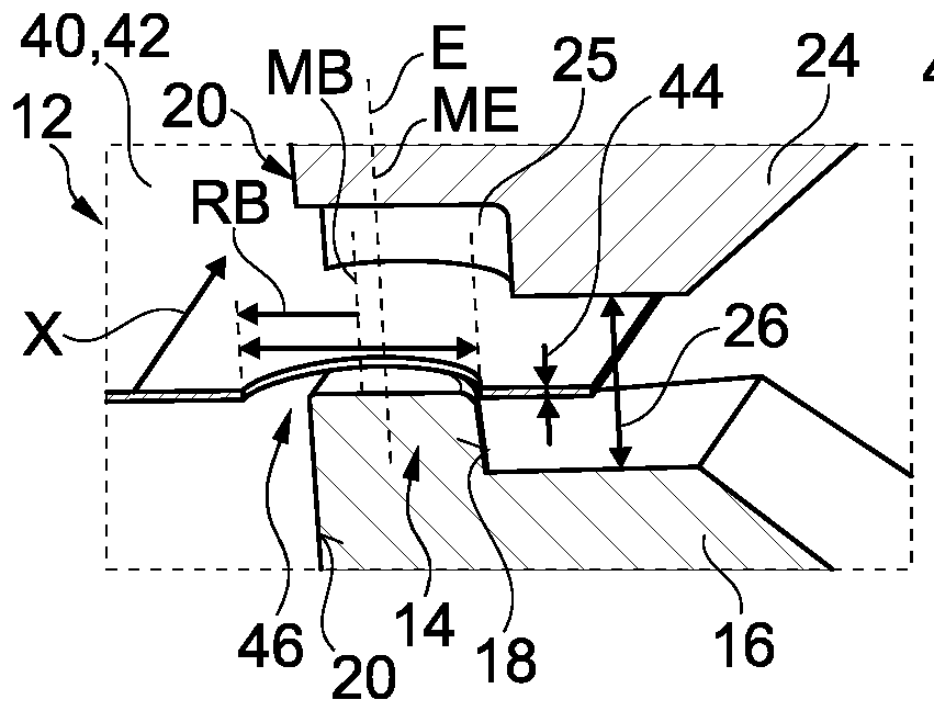
3 : ein weiteres Detail der Greifeinrichtung in einer Schnittansicht.
-
1 : a gripping device in a perspective view, -
2 : an enlarged detail of the1 , and -
3 : another detail of the gripping device in a sectional view.
Die Greifeinrichtung 10 der
Vier der Greifmechanismen 12 greifen vorliegend jeweils über einen Eingriffspin 14, der auf einem Eingriffspin-Halter 16 monolithisch mit diesem angeordnet ist, in die Bohrungen 46 ein. Jeweils zwei Eingriffspins 14 liegen quer zur Herstellungsrichtung X gegenüber und greifen formschlüssig entlang jeweils einer Eingriffsachse E in das Blech 42 ein, wie sich in den
Alle Eingriffspins 14 weisen jeweils einen zur Eingriffsachse E konisch verlaufenden Außenflächenabschnitt 18 auf, der zur Zentrierung des Blechs 42 beim Eingreifen dient; dies ist am besten in
Der Außenflächenabschnitt 18 eines jeden Eingriffspins 14 ist jeweils abgewandt vom gegenüberliegenden Eingriffspin 14 angeordnet, wie ebenfalls
Die Eingriffspins 14 sind im Grunde in einer Ebene angeordnet bzw. spannen diese Ebene auf und weisen einen verstellbaren, und vorliegend gleichen Abstand 22 entlang der Herstellungsrichtung X zueinander auf. „Im Grunde in einer Ebene“ deswegen, weil die Greifermechanismen 12 vorliegend ferner dazu ausgebildet sind, auch die Eingriffspin-Halter 16 bzw. Eingriffspins 14 über eine Länge, die im Wesentlichen zum kollisionsfreien Einsetzen und Herausnehmen eines Blechs 42 aus dem Greifermechanismus 12 gewählt ist, vertikal bzw. entlang der Eingriffsachse E zu bewegen. Deshalb liegen die Eingriffspins 14 nicht immer wortsinngemäß, aber dennoch „im Grunde“, in einer Ebene.The engagement pins 14 are basically arranged in one plane or span this plane and have an adjustable and in this case
Die gegenüberliegenden Eingriffspins 14, insbesondere die Eingriffsachsen E, sind um den Abstand 28 quer zur Herstellungsrichtung X voneinander beabstandet. Der Abstand 28 entspricht zumindest im Wesentlichen einer Breite des Blechs 42. Der Abstand 28 kann auch einstellbar sein, ist aber vorzugsweise konstant.The opposing engagement pins 14, in particular the engagement axes E, are spaced apart from one another by the
Der Eingriffspin 14 auf seinem Eingriffspin-Halter 16 ist korrespondierend zu einem Gegenhalter 24 ausgebildet, vgl.
In
In
Der Gegenhalter 24 und der Eingriffspin 14 sind mittels des vorliegenden Greifmechanismus 2 auf der Eingriffsachse E gegensinnig entlang der Eingriffsachse E pneumatisch verstellbar. Hierzu ist eine Führung 32 vorgesehen, die pneumatisch angesteuert ist und so den Eingriffspin-Halter 16 und den Gegenhalter 24 mit jeweils zumindest näherungsweiser gleicher Geschwindigkeit (je nach Pneumatik-Parametern) und/oder gleicher Wegstrecke (ca. die Hälfte des ursprünglichen Abstands 26) aufeinander zu und voneinander wegbewegen kann. Die Führung 32 ist zum Durchführen einer linearen Bewegung von Eingriffspin-Halter 16 bzw. Gegenhalter 24 ausgebildet. Die Führung 32 kann jedoch auch dazu ausgebildet sein, eine nichtlineare Bewegung durchzuführen, beispielsweise um eine bzw. die Bewegungsbahn abzubilden. Beispielsweise kann die Führung 32 einen Exzenter und/oder einen Roboterarm oder dergleichen aufweisen.The
Am Eingriffspin-Halter 16 hat der Eingriffspin 14 eine Höhe 17 von 5 mm. Andere Höhen sind auch denkbar, beispielsweise 3 mm, 4 mm, 6 mm, 7 mm bis zu 20 mm. Die Höhe 17 ragt zumindest nahezu vollständig durch die Bohrung 46 durch, wenn das Blech 42 wie beispielsweise in
Der Eingriffspin 14 weist im Bereich des Außenflächenabschnitts 18 bzw. im Übergang vom Außenflächenabschnitt 18 zur Oberseite des Eingriffspins 14 eine Materialrücknahme 19 in Form einer Verrundung auf, was das Eingreifen in die Bohrung 46 erleichtert.The
Der Außenflächenabschnitt 18 verläuft unter einem Winkel W bzw. Konuswinkel, hier relativ zur Eingriffsachse E, zu den Abflachungen 20 und zu einer Normalen in Bezug auf die Ebene, in der das gegriffene Blech liegen soll, von 5° bzw. 5°+/-1 °. Gerade mit diesem Winkel kann auf einem kurzen Weg zentriert und es kann eine genügend große Vorspannung auf das Blech aufgebaut werden.The
Insbesondere, aber auch vorliegend, bildet die Eingriffsachse E auch eine Mittelachse ME des Eingriffspins 14, wobei die Mittelachse ME von dem konisch verlaufenden Außenflächenabschnitt 18 umlaufend gleichbeabstandet umgeben sein sollte bzw. ist.In particular, but also in the present case, the engagement axis E also forms a central axis ME of the
In anderen denkbaren Ausführungsformen könnte auch die Eingriffsachse E von der Mittelachse ME abweichend positioniert sein; beispielsweise, wenn die Eingriffsachse E eine Bewegungsbahn ist, die nicht vollständig zur Form des Eingriffspins 14 korrespondiert und/oder wenigstens abschnittsweise nichtlinear bzw. gekrümmt verläuft.In other conceivable embodiments, the engagement axis E could also be positioned differently from the central axis ME; for example, if the engagement axis E is a movement path that does not completely correspond to the shape of the
Vorzugsweise - ebenfalls wie vorliegend - weist der Eingriffspin 14 um die Eingriffsachse E bzw. Mittelachse ME angrenzend an den Eingriffspin-Halter 16, sozusagen an der dicksten Stelle des Eingriffspins 14, einen Radius RE auf, der z.B. bis zu 50 % kleiner als der Radius RB der Bohrung 46 sein sollte. Der Radius RE kann aber auch dem Radius RB entsprechen. Beispielsweise ist ein Radius RE von 3 bis 6 mm vorgesehen, wenn der Radius RB der Bohrung 46 etwa 4 bis 8 mm beträgt.Preferably - also as in the present case - the
Wie insbesondere in
BezugszeichenlisteList of reference symbols
- 1010
- GreifeinrichtungGripping device
- 1212
- GreifmechanismusGripping mechanism
- 1414
- EingriffspinIntervention pin
- 1616
- Eingriffspin-HalterIntervention pin holder
- 1717
- Höhe des EingriffspinsHeight of the engagement pin
- 1818
- AußenflächenabschnittOuter surface section
- 1919
- MaterialrücknahmeMaterial return
- 2020
- AbflachungFlattening
- 2222
- Abstand der Eingriffspins entlang der HerstellungsrichtungDistance of engagement pins along the manufacturing direction
- 2424
- GegenhalterCounterholder
- 2525
- Kavitätcavity
- 2626
- Abstand von Gegenhalter und Eingriffspin-HalterDistance between counterholder and engagement pin holder
- 2828
- Abstand der Eingriffspins quer zur HerstellungsrichtungDistance of the engagement pins transverse to the manufacturing direction
- 3030
- Abstand von Gegenhalter und EingriffspinDistance between counterholder and engagement pin
- 3232
- Führung des Greifermechanismus Guide of the gripper mechanism
- 4040
- BipolarplatteBipolar plate
- 4242
- Blechsheet
- 4444
- Dickethickness
- 4646
- Bohrung Drilling
- 5050
- Werkzeugvorrichtung Tool device
- EE
- EingriffsachseEngagement axis
- MBMB
- Mittelachse BohrungCenter axis bore
- MEMY
- Mittelachse EingriffspinCenter axis engagement pin
- WW
- Winkel AußenflächenabschnittAngle outer surface section
- RBRB
- Radius BohrungRadius hole
- RERE
- Radius EingriffspinRadius engagement pin
- XX
- HerstellungsrichtungProduction direction
Claims (10)
Priority Applications (2)
| Application Number | Priority Date | Filing Date | Title |
|---|---|---|---|
| DE102022114502.6A DE102022114502B4 (en) | 2022-06-09 | 2022-06-09 | Gripping device for gripping during the manufacture of a bipolar plate |
| EP23173852.7A EP4289524A1 (en) | 2022-06-09 | 2023-05-17 | Gripping device for gripping during the production of a bipolar plate |
Applications Claiming Priority (1)
| Application Number | Priority Date | Filing Date | Title |
|---|---|---|---|
| DE102022114502.6A DE102022114502B4 (en) | 2022-06-09 | 2022-06-09 | Gripping device for gripping during the manufacture of a bipolar plate |
Publications (2)
| Publication Number | Publication Date |
|---|---|
| DE102022114502A1 DE102022114502A1 (en) | 2023-12-14 |
| DE102022114502B4 true DE102022114502B4 (en) | 2024-08-01 |
Family
ID=86387014
Family Applications (1)
| Application Number | Title | Priority Date | Filing Date |
|---|---|---|---|
| DE102022114502.6A Active DE102022114502B4 (en) | 2022-06-09 | 2022-06-09 | Gripping device for gripping during the manufacture of a bipolar plate |
Country Status (2)
| Country | Link |
|---|---|
| EP (1) | EP4289524A1 (en) |
| DE (1) | DE102022114502B4 (en) |
Citations (1)
| Publication number | Priority date | Publication date | Assignee | Title |
|---|---|---|---|---|
| DE102019109327A1 (en) | 2018-04-19 | 2019-10-24 | Toyota Jidosha Kabushiki Kaisha | A method of conveying a fuel cell separator material |
Family Cites Families (4)
| Publication number | Priority date | Publication date | Assignee | Title |
|---|---|---|---|---|
| GB801637A (en) * | 1955-04-15 | 1958-09-17 | Budd Co | Server or handler for transferring articles from one machine or position to another |
| CN102233391A (en) * | 2011-03-02 | 2011-11-09 | 浙江博雷重型机床制造有限公司 | Feeding mechanism of computer numerical control (CNC) punching machine tool |
| CN105478611A (en) * | 2014-09-19 | 2016-04-13 | 扬州恒德模具有限公司 | Clamp |
| ES2798024B2 (en) * | 2019-06-04 | 2021-05-13 | Trilla Miquel Sarabia | IMPROVED PNEUMATIC GRIPPER FOR STAMPING PRESS WITH TRANSFER SYSTEM |
-
2022
- 2022-06-09 DE DE102022114502.6A patent/DE102022114502B4/en active Active
-
2023
- 2023-05-17 EP EP23173852.7A patent/EP4289524A1/en active Pending
Patent Citations (1)
| Publication number | Priority date | Publication date | Assignee | Title |
|---|---|---|---|---|
| DE102019109327A1 (en) | 2018-04-19 | 2019-10-24 | Toyota Jidosha Kabushiki Kaisha | A method of conveying a fuel cell separator material |
Also Published As
| Publication number | Publication date |
|---|---|
| EP4289524A1 (en) | 2023-12-13 |
| DE102022114502A1 (en) | 2023-12-14 |
Similar Documents
| Publication | Publication Date | Title |
|---|---|---|
| EP1999048B1 (en) | Gripping element | |
| EP3074152B1 (en) | Tool set-up system for a brake press | |
| EP2140954A1 (en) | Method and device for manufacturing finely cut sections from a strip of material | |
| EP3790681B1 (en) | Device and method for the removal of a workpiece | |
| DE69807723T2 (en) | DEVICE FOR CLAMPING, GUIDING AND CONVEYING THE EDGES OF A CUT FILM SHEET IN A MACHINE FOR PRODUCING STRETCH METAL | |
| EP2233626B1 (en) | Insertion aid for filling needle plates | |
| DE102022114502B4 (en) | Gripping device for gripping during the manufacture of a bipolar plate | |
| EP3605752B1 (en) | Cable changing device and method for locking a cable rake adjustable in height relative to a cable feeding device | |
| WO2015106961A1 (en) | Method for creating through-passages in a metal body by means of high-speed impact cutting | |
| DE112005000553B4 (en) | Punching tool, arrangement and method for punching an oblique metering opening through a metering disk for a fuel injection valve | |
| DE1937818A1 (en) | Method and device for punching out hexagonal blanks | |
| DE102018003622A1 (en) | Device and method for cutting out a workpiece | |
| DE202018002305U1 (en) | Device for separating a workpiece | |
| EP1853785B1 (en) | Method for producing spacers for insulating glass panes | |
| DE4210608A1 (en) | Method for drop forging of elongated products on a multiple die and device for carrying it out | |
| DE2655323A1 (en) | DEVICE FOR FORMING A SINGLE METALLIC WORKPIECE | |
| DE102005047620B9 (en) | Retaining module for rolling balls | |
| DE202020101249U1 (en) | Cutting floor | |
| EP3689545A1 (en) | Jaw for tensioning a workpiece | |
| DE102018125869A1 (en) | Device for supporting at least one component | |
| DE102007024711B4 (en) | Device and method for clinching components | |
| AT392251B (en) | DEVICE FOR ALIGNING A DURABLE DEFORMABLE CONNECTOR | |
| DE10340794A1 (en) | Process and sequential tooling assembly to fabricate complex three-dimensional sheet metal component with one or more apertures | |
| DE112024001799T5 (en) | DEVICE FOR HANDLING CONTAINERS | |
| DE10058193C2 (en) | Sheet metal board with at least one press-in bolt and method for its production |
Legal Events
| Date | Code | Title | Description |
|---|---|---|---|
| R012 | Request for examination validly filed | ||
| R016 | Response to examination communication | ||
| R018 | Grant decision by examination section/examining division | ||
| R020 | Patent grant now final |