DE102022107017A1 - Surgical instrument with an extendable and energized loop made of a metallic wire - Google Patents
Surgical instrument with an extendable and energized loop made of a metallic wire Download PDFInfo
- Publication number
- DE102022107017A1 DE102022107017A1 DE102022107017.4A DE102022107017A DE102022107017A1 DE 102022107017 A1 DE102022107017 A1 DE 102022107017A1 DE 102022107017 A DE102022107017 A DE 102022107017A DE 102022107017 A1 DE102022107017 A1 DE 102022107017A1
- Authority
- DE
- Germany
- Prior art keywords
- contact
- metallic wire
- surgical instrument
- section
- slide
- Prior art date
- Legal status (The legal status is an assumption and is not a legal conclusion. Google has not performed a legal analysis and makes no representation as to the accuracy of the status listed.)
- Pending
Links
- 239000004020 conductor Substances 0.000 claims abstract description 7
- 239000002184 metal Substances 0.000 claims description 10
- 230000007423 decrease Effects 0.000 claims description 5
- 238000010292 electrical insulation Methods 0.000 description 6
- 230000005611 electricity Effects 0.000 description 3
- 238000013021 overheating Methods 0.000 description 3
- 239000004033 plastic Substances 0.000 description 3
- 229910001285 shape-memory alloy Inorganic materials 0.000 description 3
- 241000673677 Viburnum lantana Species 0.000 description 2
- 238000010438 heat treatment Methods 0.000 description 2
- 238000004519 manufacturing process Methods 0.000 description 2
- 229910001000 nickel titanium Inorganic materials 0.000 description 2
- HLXZNVUGXRDIFK-UHFFFAOYSA-N nickel titanium Chemical compound [Ti].[Ti].[Ti].[Ti].[Ti].[Ti].[Ti].[Ti].[Ti].[Ti].[Ti].[Ni].[Ni].[Ni].[Ni].[Ni].[Ni].[Ni].[Ni].[Ni].[Ni].[Ni].[Ni].[Ni].[Ni] HLXZNVUGXRDIFK-UHFFFAOYSA-N 0.000 description 2
- BUHVIAUBTBOHAG-FOYDDCNASA-N (2r,3r,4s,5r)-2-[6-[[2-(3,5-dimethoxyphenyl)-2-(2-methylphenyl)ethyl]amino]purin-9-yl]-5-(hydroxymethyl)oxolane-3,4-diol Chemical compound COC1=CC(OC)=CC(C(CNC=2C=3N=CN(C=3N=CN=2)[C@H]2[C@@H]([C@H](O)[C@@H](CO)O2)O)C=2C(=CC=CC=2)C)=C1 BUHVIAUBTBOHAG-FOYDDCNASA-N 0.000 description 1
- 201000004458 Myoma Diseases 0.000 description 1
- 230000008878 coupling Effects 0.000 description 1
- 238000010168 coupling process Methods 0.000 description 1
- 238000005859 coupling reaction Methods 0.000 description 1
- 230000001419 dependent effect Effects 0.000 description 1
- 238000011161 development Methods 0.000 description 1
- 230000018109 developmental process Effects 0.000 description 1
- 238000006073 displacement reaction Methods 0.000 description 1
- 230000017525 heat dissipation Effects 0.000 description 1
- 238000009413 insulation Methods 0.000 description 1
- 239000004810 polytetrafluoroethylene Substances 0.000 description 1
- 229920001343 polytetrafluoroethylene Polymers 0.000 description 1
Images
Classifications
-
- A—HUMAN NECESSITIES
- A61—MEDICAL OR VETERINARY SCIENCE; HYGIENE
- A61B—DIAGNOSIS; SURGERY; IDENTIFICATION
- A61B18/00—Surgical instruments, devices or methods for transferring non-mechanical forms of energy to or from the body
- A61B18/04—Surgical instruments, devices or methods for transferring non-mechanical forms of energy to or from the body by heating
- A61B18/12—Surgical instruments, devices or methods for transferring non-mechanical forms of energy to or from the body by heating by passing a current through the tissue to be heated, e.g. high-frequency current
- A61B18/14—Probes or electrodes therefor
-
- A—HUMAN NECESSITIES
- A61—MEDICAL OR VETERINARY SCIENCE; HYGIENE
- A61B—DIAGNOSIS; SURGERY; IDENTIFICATION
- A61B17/00—Surgical instruments, devices or methods
- A61B2017/00831—Material properties
- A61B2017/00867—Material properties shape memory effect
-
- A—HUMAN NECESSITIES
- A61—MEDICAL OR VETERINARY SCIENCE; HYGIENE
- A61B—DIAGNOSIS; SURGERY; IDENTIFICATION
- A61B18/00—Surgical instruments, devices or methods for transferring non-mechanical forms of energy to or from the body
- A61B2018/00053—Mechanical features of the instrument of device
- A61B2018/00059—Material properties
- A61B2018/00071—Electrical conductivity
- A61B2018/00077—Electrical conductivity high, i.e. electrically conducting
-
- A—HUMAN NECESSITIES
- A61—MEDICAL OR VETERINARY SCIENCE; HYGIENE
- A61B—DIAGNOSIS; SURGERY; IDENTIFICATION
- A61B18/00—Surgical instruments, devices or methods for transferring non-mechanical forms of energy to or from the body
- A61B2018/00571—Surgical instruments, devices or methods for transferring non-mechanical forms of energy to or from the body for achieving a particular surgical effect
- A61B2018/00589—Coagulation
-
- A—HUMAN NECESSITIES
- A61—MEDICAL OR VETERINARY SCIENCE; HYGIENE
- A61B—DIAGNOSIS; SURGERY; IDENTIFICATION
- A61B18/00—Surgical instruments, devices or methods for transferring non-mechanical forms of energy to or from the body
- A61B2018/00571—Surgical instruments, devices or methods for transferring non-mechanical forms of energy to or from the body for achieving a particular surgical effect
- A61B2018/00601—Cutting
-
- A—HUMAN NECESSITIES
- A61—MEDICAL OR VETERINARY SCIENCE; HYGIENE
- A61B—DIAGNOSIS; SURGERY; IDENTIFICATION
- A61B18/00—Surgical instruments, devices or methods for transferring non-mechanical forms of energy to or from the body
- A61B2018/00571—Surgical instruments, devices or methods for transferring non-mechanical forms of energy to or from the body for achieving a particular surgical effect
- A61B2018/00625—Vaporization
-
- A—HUMAN NECESSITIES
- A61—MEDICAL OR VETERINARY SCIENCE; HYGIENE
- A61B—DIAGNOSIS; SURGERY; IDENTIFICATION
- A61B18/00—Surgical instruments, devices or methods for transferring non-mechanical forms of energy to or from the body
- A61B2018/0091—Handpieces of the surgical instrument or device
- A61B2018/00916—Handpieces of the surgical instrument or device with means for switching or controlling the main function of the instrument or device
- A61B2018/00922—Handpieces of the surgical instrument or device with means for switching or controlling the main function of the instrument or device by switching or controlling the treatment energy directly within the hand-piece
-
- A—HUMAN NECESSITIES
- A61—MEDICAL OR VETERINARY SCIENCE; HYGIENE
- A61B—DIAGNOSIS; SURGERY; IDENTIFICATION
- A61B18/00—Surgical instruments, devices or methods for transferring non-mechanical forms of energy to or from the body
- A61B2018/0091—Handpieces of the surgical instrument or device
- A61B2018/00916—Handpieces of the surgical instrument or device with means for switching or controlling the main function of the instrument or device
- A61B2018/0094—Types of switches or controllers
- A61B2018/00946—Types of switches or controllers slidable
-
- A—HUMAN NECESSITIES
- A61—MEDICAL OR VETERINARY SCIENCE; HYGIENE
- A61B—DIAGNOSIS; SURGERY; IDENTIFICATION
- A61B18/00—Surgical instruments, devices or methods for transferring non-mechanical forms of energy to or from the body
- A61B18/04—Surgical instruments, devices or methods for transferring non-mechanical forms of energy to or from the body by heating
- A61B18/12—Surgical instruments, devices or methods for transferring non-mechanical forms of energy to or from the body by heating by passing a current through the tissue to be heated, e.g. high-frequency current
- A61B18/14—Probes or electrodes therefor
- A61B2018/1405—Electrodes having a specific shape
- A61B2018/1407—Loop
-
- A—HUMAN NECESSITIES
- A61—MEDICAL OR VETERINARY SCIENCE; HYGIENE
- A61B—DIAGNOSIS; SURGERY; IDENTIFICATION
- A61B18/00—Surgical instruments, devices or methods for transferring non-mechanical forms of energy to or from the body
- A61B18/04—Surgical instruments, devices or methods for transferring non-mechanical forms of energy to or from the body by heating
- A61B18/12—Surgical instruments, devices or methods for transferring non-mechanical forms of energy to or from the body by heating by passing a current through the tissue to be heated, e.g. high-frequency current
- A61B18/14—Probes or electrodes therefor
- A61B2018/1405—Electrodes having a specific shape
- A61B2018/144—Wire
-
- A—HUMAN NECESSITIES
- A61—MEDICAL OR VETERINARY SCIENCE; HYGIENE
- A61B—DIAGNOSIS; SURGERY; IDENTIFICATION
- A61B18/00—Surgical instruments, devices or methods for transferring non-mechanical forms of energy to or from the body
- A61B18/04—Surgical instruments, devices or methods for transferring non-mechanical forms of energy to or from the body by heating
- A61B18/12—Surgical instruments, devices or methods for transferring non-mechanical forms of energy to or from the body by heating by passing a current through the tissue to be heated, e.g. high-frequency current
- A61B18/14—Probes or electrodes therefor
- A61B2018/1475—Electrodes retractable in or deployable from a housing
-
- A—HUMAN NECESSITIES
- A61—MEDICAL OR VETERINARY SCIENCE; HYGIENE
- A61B—DIAGNOSIS; SURGERY; IDENTIFICATION
- A61B18/00—Surgical instruments, devices or methods for transferring non-mechanical forms of energy to or from the body
- A61B18/04—Surgical instruments, devices or methods for transferring non-mechanical forms of energy to or from the body by heating
- A61B18/12—Surgical instruments, devices or methods for transferring non-mechanical forms of energy to or from the body by heating by passing a current through the tissue to be heated, e.g. high-frequency current
- A61B18/14—Probes or electrodes therefor
- A61B18/16—Indifferent or passive electrodes for grounding
- A61B2018/162—Indifferent or passive electrodes for grounding located on the probe body
Landscapes
- Health & Medical Sciences (AREA)
- Surgery (AREA)
- Engineering & Computer Science (AREA)
- Life Sciences & Earth Sciences (AREA)
- Biomedical Technology (AREA)
- Otolaryngology (AREA)
- Nuclear Medicine, Radiotherapy & Molecular Imaging (AREA)
- Plasma & Fusion (AREA)
- Physics & Mathematics (AREA)
- Heart & Thoracic Surgery (AREA)
- Medical Informatics (AREA)
- Molecular Biology (AREA)
- Animal Behavior & Ethology (AREA)
- General Health & Medical Sciences (AREA)
- Public Health (AREA)
- Veterinary Medicine (AREA)
- Surgical Instruments (AREA)
Abstract
Bereitgestellt wird ein Chirurgisches Instrument (10) mit einem Handgriff (60) und einem rohrförmigen Schaft (20) mit einem Innenraum und einer Wandung (22) aus einem elektrisch leitenden Material, wobei in einem Innenraum des rohrförmigen Schafts (20) ein metallischer Draht (30) zumindest abschnittsweise und durch Betätigung eines Bedienelements (41) verschiebbar angeordnet ist, so dass eine aus einem distalen Ende des Schafts (20) ausfahrbare Schlinge (33) gebildet wird und mit einem Schalter, durch dessen Betätigung der metallische Draht (30) bestromt werden kann, bei dem das Bedienelement (41) und der Schalter miteinander gekoppelt sind, so dass eine Bestromung des metallischen Drahts (30) lediglich bei einer oder mehreren definierten Positionen des metallischen Drahts (30) erfolgt.A surgical instrument (10) is provided with a handle (60) and a tubular shaft (20) with an interior and a wall (22) made of an electrically conductive material, a metallic wire (20) being located in an interior of the tubular shaft (20). 30) is arranged displaceably at least in sections and by actuating a control element (41), so that a loop (33) which can be extended from a distal end of the shaft (20) is formed and with a switch, the actuation of which energizes the metallic wire (30). can be, in which the control element (41) and the switch are coupled to one another, so that the metallic wire (30) is energized only at one or more defined positions of the metallic wire (30).
Description
Die Erfindung betrifft ein chirurgisches Instrument mit einer ausfahrbaren und bestrombaren Schlinge aus einem metallischen Draht gemäß dem Oberbegriff des Patentanspruchs 1.The invention relates to a surgical instrument with an extendable and energized loop made of a metallic wire according to the preamble of patent claim 1.
Bekannt sind chirurgische Instrumente mit einem Schaft, welcher eine Längsachse, ein proximales Ende und distales Ende aufweist, und mit einer ausfahrbaren Schlinge aus einem metallischen Draht. Ausfahrbar bedeutet dabei, dass die Position zumindest von Abschnitten des metallischen Drahts innerhalb des Schaftes veränderlich ist, so dass beispielsweise die Position der Schlinge relativ zum distalen Ende des Schaftes und/oder ihre Größe veränderbar ist. Ein Beispiel für ein solches chirurgisches Instruments offenbart die
Grundsätzlich kann der metallische Draht mit Strom beaufschlagbar sein, er kann aber auch ohne Strom verwendet werden. Wird der metallische Draht ohne Strom verwendet, kann das chirurgische Instrument beispielsweise zur Dilatation oder Dissektion von Gewebe verwendet werden. Bei Beaufschlagung des metallischen Drahts mit Strom kann das chirurgische Instrument zur Resektion von Gewebe, beispielsweise von Polypen oder Myomen, zur Koagulation von Gewebe oder zur Vaporisation von Gewebe verwendet werden. Dabei kann das Instrument sowohl in einer monopolaren als auch in einer bipolaren Ausführung verwendet werden.In principle, the metallic wire can be supplied with electricity, but it can also be used without electricity. If the metallic wire is used without electricity, the surgical instrument can be used, for example, to dilate or dissect tissue. When current is applied to the metallic wire, the surgical instrument can be used to resect tissue, for example polyps or myomas, to coagulate tissue or to vaporize tissue. The instrument can be used in both a monopolar and a bipolar version.
Bei der praktischen Verwendung von chirurgischen Instrumenten, deren metallischer Draht mit Strom beaufschlagbar ist, zeigt es sich, dass die Bestromung des metallischen Drahts in bestimmten Positionen der Schlinge zu Problemen führt. Dies gilt insbesondere in Positionen, in denen die Abfuhr der bei der Bestromung des metallischen Drahts entstehenden Wärme nicht gewährleistet ist, so dass es zu einer lokalen Überhitzung des metallischen Drahts kommt. Besonders kritisch wirkt sich eine solche Überhitzung bei metallischen Drähten aus einer Formgedächtnislegierung wie z.B. Nitinol aus, denen bei der Produktion des chirurgischen Instruments eine definierte Form eingelernt wird, die der aus dem Schaft herausgefahrene Abschnitt des metallischen Drahts und insbesondere eine durch diesen gebildete Schlinge einnehmen soll, weil dabei eine neue, undefinierte Form eingelernt wird, die dann die bestimmungsgemäße Verwendung des chirurgischen Instruments erschwert oder vollständig unmöglich werden lässt.In the practical use of surgical instruments whose metallic wire can be energized, it turns out that energizing the metallic wire leads to problems in certain positions of the loop. This applies in particular in positions in which the dissipation of the heat generated when the metallic wire is energized is not guaranteed, so that local overheating of the metallic wire occurs. Such overheating is particularly critical in the case of metallic wires made of a shape memory alloy such as Nitinol, for which a defined shape is taught during the production of the surgical instrument, which the section of the metallic wire that is extended out of the shaft and in particular a loop formed by it should assume , because a new, undefined form is learned, which then makes the intended use of the surgical instrument more difficult or completely impossible.
Die Aufgabe der Erfindung besteht darin, ein chirurgisches Instrument mit einer ausfahrbaren und bestrombaren Schlinge aus einem metallischen Draht derart weiterzubilden, dass eine übermäßige Erhitzung von Abschnitten des metallischen Drahts mit höherer Sicherheit vermieden wird.The object of the invention is to develop a surgical instrument with an extendable and energized loop made of a metallic wire in such a way that excessive heating of sections of the metallic wire is avoided with greater safety.
Die Aufgabe der Erfindung wird gelöst durch ein chirurgisches Instrument mit den Merkmalen des Patentanspruchs 1. Vorteilhafte Ausgestaltungen und Weiterbildungen der Erfindung sind in den abhängigen Ansprüchen angegeben.The object of the invention is achieved by a surgical instrument with the features of patent claim 1. Advantageous refinements and developments of the invention are specified in the dependent claims.
Das erfindungsgemäße chirurgische Instrument hat einen vorzugsweise durch ein Gehäuse gebildeten Handgriff und einen rohrförmigen Schaft mit einem Innenraum und einer Wandung aus einem elektrisch leitenden Material. In einem Innenraum des rohrförmigen Schafts ist ein metallischer Draht, der vorzugsweise aus einer Formgedächtnislegierung wie z.B. Nitinol bestehen kann, zumindest abschnittsweise und durch Betätigung eines Bedienelements verschiebbar angeordnet, so dass eine aus einem distalen Ende des Schafts ausfahrbare Schlinge gebildet wird. Das chirurgische Instrument weist weiterhin einen Schalter auf, durch dessen Betätigung der metallische Draht bestromt werden kann. Dementsprechend ist das distale Ende des chirurgischen Instruments das, an dem die Schlinge angeordnet ist; sein proximales Ende ist das dem distalen Ende gegenüber liegende Ende, wodurch die proximale bzw. distale Richtung bezogen auf das Gerät eindeutig definiert sind.The surgical instrument according to the invention has a handle, preferably formed by a housing, and a tubular shaft with an interior and a wall made of an electrically conductive material. In an interior of the tubular shaft, a metallic wire, which can preferably consist of a shape memory alloy such as Nitinol, is arranged at least in sections and can be moved by actuating a control element, so that a loop that can be extended from a distal end of the shaft is formed. The surgical instrument also has a switch, by actuating which the metallic wire can be energized. Accordingly, the distal end of the surgical instrument is that on which the sling is placed; its proximal end is the end opposite the distal end, whereby the proximal and distal directions are clearly defined in relation to the device.
Die ausfahrbare Schlinge wird dabei vorzugsweise dadurch gebildet, dass ein Ende des metallischen Drahtes am distalen Ende der Wandung aus elektrisch leitendem Material des rohrförmigen Schafts in leitendem Kontakt befestigt ist; prinzipiell können aber auch zwei Abschnitte des metallischen Drahts voneinander elektrisch isoliert in dem Innenraum des rohrförmigen Schafts geführt sein.The extendable loop is preferably formed in that one end of the metallic wire is attached in conductive contact to the distal end of the wall made of electrically conductive material of the tubular shaft; In principle, however, two sections of the metallic wire can also be electrically insulated from one another in the interior of the tubular shaft.
Es versteht sich dabei, dass in radialer Richtung zur Rohrmittelachse des rohrförmigen Schafts eine elektrische Isolierung den metallischen Draht in den Abschnitten die mit der Wandung aus elektrisch leitendem Material in Kontakt kommen können, vorhanden ist.It goes without saying that in the radial direction to the tube center axis of the tubular shaft, there is electrical insulation for the metallic wire in the sections that can come into contact with the wall made of electrically conductive material.
Erfindungswesentlich ist, dass das Bedienelement und der Schalter miteinander gekoppelt sind, so dass eine Bestromung des metallischen Drahts lediglich bei einer oder mehreren definierten Positionen des metallischen Drahts erfolgt. Das Bedienelement dient mit anderen Worten gesagt also sowohl dazu, die mechanische Positionsänderung des metallischen Drahts herbeizuführen, als auch den Schalter in eine andere Schaltposition zu bringen. Auf diese Weise kann sichergestellt werden, dass ein Stromfluss und damit eine Erwärmung des metallischen Drahts nur in bestimmten Positionen des metallischen Drahts erfolgen kann.It is essential to the invention that the control element and the switch are coupled to one another, so that the metallic wire is only energized at one or more defined positions of the metallic wire. In other words, the control element serves both to bring about the mechanical change in position of the metallic wire and to bring the switch into a different switching position. In this way it can be ensured that current flow and thus heating of the metallic wire can only take place in certain positions of the metallic wire.
Besonders bevorzugt ist es dabei, wenn eine Bestromung des metallischen Drahts lediglich in der Position des Bedienelements erfolgt, in der die ausfahrbare Schlinge so weit wie möglich ausgefahren ist. Dadurch wird sicher vermieden, dass Abschnitte des metallischen Drahts, die zur Bildung der ausfahrbaren Schlinge verwendet werden, durch Bestromung erwärmt werden, während sie innerhalb des rohrförmigen Schafts angeordnet sind, der dann die Wärmeabfuhr verhindert und zu einer Überhitzung des metallischen Drahts führt, die beispielsweise wenn der metallische Draht aus einer Formgedächtnislegierung besteht, der eine gewünschte Schlingenform eingelernt ist, diese Schlingenform ändern kann.It is particularly preferred if the metallic wire is only energized in the position of the operating element in which the extendable loop is extended as far as possible. This safely avoids that sections of the metallic wire used to form the extendable loop are heated by current while they are arranged within the tubular shaft, which then prevents heat dissipation and leads to overheating of the metallic wire, for example if the metallic wire consists of a shape memory alloy, which is taught a desired loop shape, this loop shape can change.
Vorteilhaft ist es, wenn das Bedienelement in der Position, in der eine Bestromung des metallischen Drahts erfolgt, gehalten wird, so dass eine Haltekraft überwunden werden muss, um das Bedienelement in eine andere Position zu bringen. Dies führt einerseits zu einem innigen elektrischen Kontakt zwischen den Schaltkontakten des Schalters und stellt andererseits sicher, dass die ausfahrbare Schlinge so weit wie möglich ausgefahren ist.It is advantageous if the control element is held in the position in which current is supplied to the metallic wire, so that a holding force must be overcome in order to bring the control element into a different position. On the one hand, this leads to intimate electrical contact between the switching contacts of the switch and, on the other hand, ensures that the extendable loop is extended as far as possible.
Darüber hinaus kann es von Vorteil sein, wenn das Bedienelement in der Position, in der die Schlinge so klein wie möglich oder vollständig in den Innenraum des rohrförmigen Schafts eingezogen ist, gehalten wird, so dass eine Haltekraft überwunden werden muss, um das Bedienelement in eine andere Position zu bringen. Auf diese Weise wird einem versehentlichen Ausfahren der Schlinge und einer versehentlichen Bestromung des metallischen Drahts entgegengewirkt.In addition, it can be advantageous if the control element is held in the position in which the loop is as small as possible or completely drawn into the interior of the tubular shaft, so that a holding force must be overcome in order to move the control element into one to bring another position. In this way, accidental extension of the loop and accidental energization of the metallic wire are counteracted.
Besonders einfach kann eine solche Haltekraft durch ein Federelement bereitgestellt werden.Such a holding force can be provided particularly easily by a spring element.
In einer besonders bevorzugten Ausführungsform der Erfindung ist das Bedienelement Bestandteil eines Schiebers, wobei der Schieber ferner einen Körper aufweist, in dem ein Endabschnitt des metallischen Drahts aufgenommen und fixiert ist. Dieser Körper ist vorteilhaft verschiebbar innerhalb des Gehäuses angeordnet und kann beispielsweise mit einem Verbindungsabschnitt mit dem Bedienelement verbunden sein. Der Verbindungsabschnitt kann in einer besonders vorteilhaften Variante in einer parallel zur Rohrmittelachse des rohrförmigen Schafts verlaufenden Ausnehmung des Gehäuses geführt sein, so dass das Bedienelement lediglich in proximale und distale Richtung verschoben werden kann, damit den Körper mitbewegt und den in diesem mit einem Endabschnitt aufgenommenen metallischen Draht entsprechend innerhalb der rohrförmigen Schafts verschiebt.In a particularly preferred embodiment of the invention, the operating element is part of a slide, the slide further having a body in which an end section of the metallic wire is received and fixed. This body is advantageously displaceable within the housing and can be connected to the control element, for example, with a connecting section. In a particularly advantageous variant, the connecting section can be guided in a recess in the housing that runs parallel to the central axis of the tubular shaft, so that the operating element can only be moved in the proximal and distal directions, so that the body moves with it and the metallic part received in it with an end section Wire moves accordingly within the tubular shaft.
Besonders einfach ist dabei die Kopplung des Bedienelements mit Schalter bei einer Ausgestaltung realisiert, bei der ein Lagerabschnitt eines Kontaktelements, welches elektrisch leitend mit dem metallischen Draht verbunden ist, im Körper des Schiebers gelagert ist und bei der ein Kontaktabschnitt des Kontaktelements aus dem Körper des Schiebers herausragt, so dass der Schieber ein Stellglied des Schalters und der Kontaktabschnitt des Kontaktelements einen ersten Schaltkontakt des Schalters bildet.The coupling of the operating element with the switch is particularly simple in an embodiment in which a bearing section of a contact element, which is electrically conductively connected to the metallic wire, is mounted in the body of the slide and in which a contact section of the contact element is protruded from the body of the slide protrudes, so that the slide forms an actuator of the switch and the contact section of the contact element forms a first switching contact of the switch.
Bevorzugt ist es in dieser Konfiguration, dass ein zweiter Schaltkontakt des Schalters durch einen distalen Endabschnitt einer als Blech ausgeführten Elektrode, die vorzugsweise die Aktivelektrode ist, die mit einem elektrischen Anschluss des chirurgischen Instruments verbunden ist, gebildet wird.In this configuration, it is preferred that a second switching contact of the switch is formed by a distal end section of an electrode designed as a sheet metal, which is preferably the active electrode, which is connected to an electrical connection of the surgical instrument.
Wenn dann der Abstand des distalen Endabschnitts der als Blech ausgeführten Elektrode von einer Mittelachse des rohrförmigen Schafts in distaler Richtung abnimmt, was insbesondere erreicht werden kann, wenn der distale Endabschnitt der als Blech ausgeführten Elektrode abgeknickt oder abgebogen vom benachbarten Abschnitt der als Blech ausgeführten Elektrode verläuft, und wenn ferner der Kontaktabschnitt des Kontaktelements eine erste Anlagefläche aufweist, die im Wesentlichen parallel zum distalen Endabschnitt der als Blech ausgeführten Elektrode verläuft, so dass durch ein Verschieben des Schiebers in distaler Richtung ein Flächenkontakt zwischen der ersten Anlagefläche und dem distalen Endabschnitt der als Blech ausgeführten Elektrode herstellbar ist, kann ein besonders guter elektrischer Kontakt gewährleistet werden.If the distance of the distal end section of the electrode designed as a sheet metal from a central axis of the tubular shaft decreases in the distal direction, which can be achieved in particular if the distal end section of the electrode designed as a sheet metal is bent or bent from the adjacent section of the electrode designed as a sheet metal , and if further the contact section of the contact element has a first contact surface which runs essentially parallel to the distal end section of the electrode designed as a sheet metal, so that by moving the slide in the distal direction, a surface contact between the first contact surface and the distal end section of the electrode designed as a sheet metal executed electrode can be produced, a particularly good electrical contact can be guaranteed.
Besonders vorteilhaft können Ausführungsformen sein, bei denen der Kontaktabschnitt des Kontaktelements eine zweite Anlagefläche aufweist, deren Abstand von der Mittelachse des rohrförmigen Schafts in proximaler Richtung abnimmt und bei denen bei geschlossenem Schalter und vollständig ausgefahrener Schlinge das Federelement an der zweiten Anlagefläche anliegt und bei Bewegung des Schiebers in proximale Richtung das Federelement durch die zweite Anlagefläche weiter gespannt wird, da so eine Haltekraft, die die Schlinge in ihrem maximal ausgefahrenen Zustand hält, einfach erzeugt werden kann.Embodiments can be particularly advantageous in which the contact section of the contact element has a second contact surface, the distance from the central axis of the tubular shaft decreases in the proximal direction and in which the spring element rests on the second contact surface when the switch is closed and the loop is fully extended and when the switch is moved Slider in the proximal direction, the spring element is further tensioned by the second contact surface, since a holding force that holds the loop in its maximum extended state can be easily generated.
Die Erfindung wird nachfolgend anhand von Figuren, die Ausführungsbeispiele zeigen, näher erläutert. Es zeigen
-
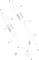
1 ein chirurgisches Instrument mit einer ausgefahrenen bestrombaren Schlinge aus einem metallischen Draht, -
2 das chirurgische Instrument aus1 mit eingefahrener bestrombarer Schlinge, -
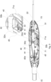
3 einen Blick in das Gehäuseinnere des chirurgischen Instruments aus1 , und -
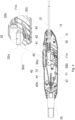
4 einen Blick in das Gehäuseinnere des chirurgischen Instruments aus2 .
-
1 a surgical instrument with an extended energized loop made of a metallic wire, -
2 the surgical instrument1 with retracted energized loop, -
3 a look inside the housing of the surgical instrument1 , and -
4 a look inside the housing of the surgical instrument2 .
Das in den
Im Inneren des rohrförmigen Schafts 20 verläuft ein metallischer Draht 30, der zumindest abschnittsweise durch Betätigung eines als Bestandteil eines Schiebers 40 ausgeführten Bedienelements 41 verschiebbar ist. In der Position des Bedienelements 41, die in
Über einen am proximalen Ende des Handgriffs 60 angeordneten elektrischen Anschluss 70 kann die Verbindung zu einer nicht gezeigten Stromquelle hergestellt werden, so dass der metallische Draht 30 und insbesondere eine Schlinge 33, die er im ausgefahrenen Zustand bildet, bestrombar ist.The connection to a power source, not shown, can be established via an
In den
Das Ende der Passivelektrode 72 kann gefedert in einem Schlitz eines Flansches 73 aus elektrisch leitendem Material aufgenommen sein, in dem auch das proximale Ende einer elektrisch leitenden rohrförmigen Wandung 22 des rohrförmigen Schafts 20 gelagert ist, so dass an dieser Stelle eine elektrisch leitende Verbindung zwischen der Passivelektrode 72 und der elektrisch leitenden rohrförmigen Wandung 22 des rohrförmigen Schafts 20 vorhanden ist, die den Passivleiter bildet. In radialer Richtung nach außen hin kann der Schaft 20 gewünschtenfalls noch mit einer elektrischen Isolierung ummantelt sein, so dass die elektrisch leitende rohrförmige Wandung 22 des rohrförmigen Schafts 20 in dieser Richtung nicht die Oberfläche des rohrförmigen Schafts 20 bildet.The end of the
Im Bereich des distalen Endes der elektrisch leitenden rohrförmigen Wandung 22 des Schafts 20 ist ein elektrischer Kontakt zum distalen Ende des metallischen Drahts 30 hergestellt, der zumindest Abschnitte aufweist, die verschiebbar im Innenraum des Schafts 20 angeordnet sind. Dabei kann der metallische Draht 30 abgesehen von seinen Kontaktabschnitten mit einer elektrischen Isolierung 31, die beispielsweise durch einen PTFE-Schlauch gebildet werden kann, umhüllt sein, so dass in den Abschnitten des metallischen Drahts 30, die im Innenraum des rohrförmigen Schafts 20 verlaufen, eine elektrische Isolierung in radialer Richtung zu der elektrisch leitenden rohrförmigen Wandung 22 des rohrförmigen Schafts 20 gewährleistet ist. Das proximale Ende des metallischen Drahts 30 ist mit einem Kontaktelement 32 verbunden.In the area of the distal end of the electrically conductive
Ein Lagerabschnitt 32a des Kontaktelements 32 kann dabei gemeinsam mit dem proximalen Endabschnitt des metallischen Drahts 30 in den Körper 42 eines Schiebers 40 aufgenommen sein, während ein Kontaktabschnitt 32b des Kontaktelements 32 aus dem Körper 42 des Schiebers 40 herausragt. Der Schieber 40 ist mit einem Verbindungsabschnitt 43 mit einem außerhalb des Gehäuses angeordneten Bedienelement 41 verbunden, wobei der Verbindungsabschnitt 43 in einem parallel zur Rohrmittelachse des rohrförmigen Schafts 20 verlaufenden Schlitz des Gehäuses geführt ist.A
Dementsprechend kann das Bedienelement 41 in Richtung parallel zur Rohrmittelachse des rohrförmigen Schafts 20 verschoben werden, was dann zu einer entsprechenden Verschiebung des Körpers 42 des Schiebers 40 führt. Wird dieser in distale Richtung bewegt, wird der im Körper 42 des Schiebers 40 aufgenommene metallische Draht 30 in dieselbe Richtung geschoben, wodurch sein distaler Endabschnitt weiter aus dem Rohrinnenraum des rohrförmigen Schafts 20 heraustritt und die Schlinge 33 bildet bzw. vergrößert. Wird der Schieber 40 in proximaler Richtung bewegt, bewegt sich der Körper 42 in diese Richtung und demzufolge wird die Schlinge 33 eingezogen.Accordingly, the
Um den Stromkreis zu schließen, muss der Kontaktabschnitt 32b, der sich mit der Bewegung des Schiebers 40 bzw. von dessen Körper in axialer Richtung verschiebt, in elektrisch leitender Verbindung zur Aktivelektrode 71 stehen. Um dies zu ermöglichen, verläuft der distale Abschnitt 71a der Aktivelektrode 71 in Richtung auf die Rohrmittelachse des rohrförmigen Schafts 20 hin und endet auf einer Höhe, in der der Kontaktabschnitt 32b liegt, so dass in der distalen Endposition des Schiebers 40 der elektrische Kontakt zwischen dem distalen Abschnitt 71a der Aktivelektrode 71 und dem Kontaktabschnitt 32b hergestellt ist und bei einer Verschiebung in proximaler Richtung verloren geht. Dementsprechend bilden der Kontaktabschnitt 32b und der distale Abschnitt 71a der Aktivelektrode 71 die Kontakte eines Schalters und der Schieber 40 das Stellelement, mit dem diese Kontakte des Schalters miteinander in Verbindung gebracht und voneinander getrennt werden können.In order to close the circuit, the
In der dargestellten Ausführungsform wird das Herstellen des elektrischen Kontakts dadurch erreicht, dass eine erste Anlagefläche 32c des Kontaktabschnitts 32b vorhanden ist, die im Wesentlichen parallel zum distalen Abschnitt der Aktivelektrode 71 verläuft, so dass ein elektrischer Flächenkontakt zwischen der ersten Anlagefläche 32c und dem distalen Abschnitt 71a der Aktivelektrode 71 entsteht, der vorzugsweise durch eine leichte Federspannung der Aktivelektrode 71 weiter verbessert wird.In the illustrated embodiment, the establishment of the electrical contact is achieved in that a
Der Kontaktabschnitt 32b weist eine zweite Anlagefläche 32d auf, die sich in proximaler Richtung an die erste Anlagefläche 32c anschließt und im Raum so verläuft, dass ihr Abstand zur Rohrmittelachse des rohrförmigen Schafts 20 in proximaler Richtung abnimmt. In der Darstellung der
Der Schieber 40 und damit auch der Kontaktabschnitt 32b des im Körper 42 des Schiebers 40 gelagerten Kontaktelements 32 wird dadurch in seiner distalen Endposition fixiert, die der geschlossenen Position des Schalters entspricht, und vorzugsweise auch gegen den distalen Abschnitt 71a der Aktivelektrode 71 gedrückt, wie dies in
Wegen des schrägen Verlaufs der zweiten Anlagefläche 32c kann jedoch bei entsprechender Krafteinleitung durch den Benutzer über das Bedienelement 41 des Schiebers 40 diese Fixierung überwunden und das flächige Federelement 65 von der Rohrmittelachse des rohrförmigen Schafts 20 weggedrückt werden, so dass der elektrische Kontakt zwischen dem Kontaktabschnitt 32b und dem distalen Abschnitt 71a der Aktivelektrode 71 gelöst und der Stromfluss unterbrochen wird. Dabei gleitet zunächst die zweite Anlagefläche 32d über die distale Kante des flächigen Federelements 65 und drückt diese nach unten, bis die Verbindungslinie zwischen erster Anlagefläche 32c und zweiter Anlagefläche 32d, die durch die Linie des Kontaktabschnitts 32b, die am weitesten von der Rohrmittelachse des rohrförmigen Schafts 20 entfernt ist, gebildet wird, das flächige Federelement 65 erreicht. Von diesem Punkt an unterstützt das flächige Federelement 65 die Bewegung des Schiebers 49 in proximale Richtung, bis er an seinem proximalen Anschlag angekommen ist.Because of the oblique course of the
Bei einem bevorzugten Verfahren zur Herstellung eines solchen chirurgischen Instruments 10 wird das den Handgriff 60 bildende Gehäuse in zwei Halbschalen 60a bereitgestellt, von denen mindestens eine die oben erwähnten Führungselemente 62, die Rippe 64 und das flächige Federelement 65 aufweisen kann. Diese Komponenten können aber auch aus an beiden Halbschalen 60a vorhandenen Teilabschnitten zusammengesetzt sein.In a preferred method for producing such a
Der mit der elektrischen Isolierung 31 ummantelte metallische Draht 30 wird mit dem Kontaktelement 32 verbunden und mit dem Schieber 40 mit Körper 42, Verbindungsstück 43 und Bedienelement 41 umspritzt, vorzugsweise mit Kunststoff.The
Die Aktivelektrode 71 und die Passivelektrode 72 werden geformt, mit den Kontakten des Anschlusses 70 verbunden und der Anschluss selbst durch Umspritzen, vorzugsweise mit Kunststoff, hergestellt.The
Die elektrisch leitende rohrförmige Wandung 22 des rohrförmigen Schafts 20 wird mit dem Flansch 73 verbunden. Anschließend wird der mit der elektrischen Isolierung 31 ummantelte metallische Draht in das Rohrinnere eingeführt, bis zum distalen Ende durchgeschoben und dort der Kontakt mit der elektrisch leitenden rohrförmigen Wandung 22 hergestellt. Ferner wird die Passivelektrode 72 in einen Schlitz im Flansch 73 eingeführt. Zur Fertigstellung der Elektrodenbaugruppe kann der Anschluss 70 mit Anschlusskabeln verbunden und mit einem Knickschutz gesichert werden.The electrically conductive
Die Elektrodenbaugruppe kann dann in eine der Halbschalen eingelegt werden, wobei insbesondere die Aktivelektrode 71 und die Passivelektrode 72 in die Führungselemente 62 eingeschoben werden, um sie zu haltern. Anschließend wird die andere Halbschale 60a des Gehäuses, das den Handgriff 60 bildet, angepresst und so das Gehäuse zusammengefügt.The electrode assembly can then be inserted into one of the half-shells, in particular the
BezugszeichenlisteReference symbol list
- 1010
- Chirurgisches InstrumentSurgical instrument
- 2020
- rohrförmiger Schafttubular shaft
- 2222
- rohrförmige Wandungtubular wall
- 3030
- metallischer Drahtmetallic wire
- 3131
- Isolierunginsulation
- 3232
- KontaktelementContact element
- 32a32a
- LagerabschnittStorage section
- 32b32b
- KontaktabschnittContact section
- 32c32c
- erste Anlageflächefirst contact area
- 32d32d
- zweite Anlageflächesecond contact area
- 3333
- Schlingeloop
- 4040
- SchieberSlider
- 4141
- BedienelementControl element
- 4242
- KörperBody
- 4343
- Verbindungsabschnittconnection section
- 6060
- HandgriffHandle
- 60a60a
- Halbschalehalf shell
- 6161
- Gehäusewandhousing wall
- 6262
- FührungselementLeadership element
- 6464
- Ripperib
- 6565
- FederelementSpring element
- 7070
- elektrischer Anschlusselectrical connection
- 7171
- AktivelektrodeActive electrode
- 71a71a
- distaler Abschnittdistal section
- 7272
- PassivelektrodePassive electrode
- 7373
- Flanschflange
ZITATE ENTHALTEN IN DER BESCHREIBUNGQUOTES INCLUDED IN THE DESCRIPTION
Diese Liste der vom Anmelder aufgeführten Dokumente wurde automatisiert erzeugt und ist ausschließlich zur besseren Information des Lesers aufgenommen. Die Liste ist nicht Bestandteil der deutschen Patent- bzw. Gebrauchsmusteranmeldung. Das DPMA übernimmt keinerlei Haftung für etwaige Fehler oder Auslassungen.This list of documents listed by the applicant was generated automatically and is included solely for the better information of the reader. The list is not part of the German patent or utility model application. The DPMA assumes no liability for any errors or omissions.
Zitierte PatentliteraturCited patent literature
- DE 102017126199 A1 [0002]DE 102017126199 A1 [0002]
Claims (10)
Priority Applications (2)
| Application Number | Priority Date | Filing Date | Title |
|---|---|---|---|
| DE102022107017.4A DE102022107017A1 (en) | 2022-03-24 | 2022-03-24 | Surgical instrument with an extendable and energized loop made of a metallic wire |
| US18/125,487 US20230301706A1 (en) | 2022-03-24 | 2023-03-23 | Surgical instrument with an extendable loop made of metal wire that can be energized |
Applications Claiming Priority (1)
| Application Number | Priority Date | Filing Date | Title |
|---|---|---|---|
| DE102022107017.4A DE102022107017A1 (en) | 2022-03-24 | 2022-03-24 | Surgical instrument with an extendable and energized loop made of a metallic wire |
Publications (1)
| Publication Number | Publication Date |
|---|---|
| DE102022107017A1 true DE102022107017A1 (en) | 2023-09-28 |
Family
ID=87930817
Family Applications (1)
| Application Number | Title | Priority Date | Filing Date |
|---|---|---|---|
| DE102022107017.4A Pending DE102022107017A1 (en) | 2022-03-24 | 2022-03-24 | Surgical instrument with an extendable and energized loop made of a metallic wire |
Country Status (2)
| Country | Link |
|---|---|
| US (1) | US20230301706A1 (en) |
| DE (1) | DE102022107017A1 (en) |
Citations (3)
| Publication number | Priority date | Publication date | Assignee | Title |
|---|---|---|---|---|
| DE10212841A1 (en) | 2002-03-22 | 2003-10-09 | Storz Karl Gmbh & Co Kg | Medical instrument for the treatment of tissue using high-frequency current and medical system with such a medical instrument |
| DE102017126199A1 (en) | 2017-11-09 | 2019-05-09 | Rz-Medizintechnik Gmbh | Surgical instrument with a loop of a metallic wire |
| DE102020118965A1 (en) | 2020-07-17 | 2022-02-10 | Olympus Winter & Ibe Gmbh | Surgical handpiece, insulating liner for a surgical handpiece and method of handling a surgical handpiece |
Family Cites Families (1)
| Publication number | Priority date | Publication date | Assignee | Title |
|---|---|---|---|---|
| US10813685B2 (en) * | 2014-09-25 | 2020-10-27 | Covidien Lp | Single-handed operable surgical instrument including loop electrode with integrated pad electrode |
-
2022
- 2022-03-24 DE DE102022107017.4A patent/DE102022107017A1/en active Pending
-
2023
- 2023-03-23 US US18/125,487 patent/US20230301706A1/en active Pending
Patent Citations (3)
| Publication number | Priority date | Publication date | Assignee | Title |
|---|---|---|---|---|
| DE10212841A1 (en) | 2002-03-22 | 2003-10-09 | Storz Karl Gmbh & Co Kg | Medical instrument for the treatment of tissue using high-frequency current and medical system with such a medical instrument |
| DE102017126199A1 (en) | 2017-11-09 | 2019-05-09 | Rz-Medizintechnik Gmbh | Surgical instrument with a loop of a metallic wire |
| DE102020118965A1 (en) | 2020-07-17 | 2022-02-10 | Olympus Winter & Ibe Gmbh | Surgical handpiece, insulating liner for a surgical handpiece and method of handling a surgical handpiece |
Also Published As
| Publication number | Publication date |
|---|---|
| US20230301706A1 (en) | 2023-09-28 |
Similar Documents
| Publication | Publication Date | Title |
|---|---|---|
| DE102018122806A1 (en) | Conductor terminal and contact insert | |
| DE4338762C2 (en) | Push button switch | |
| WO2017102829A1 (en) | Conductor connection terminal | |
| EP0553694A2 (en) | Electrical switch | |
| DE102020105813A1 (en) | Spring clamp connection | |
| DE102017117509A1 (en) | Electric device | |
| DE3320438A1 (en) | SWITCH ARRANGEMENT | |
| DE3815883A1 (en) | DEVICE SWITCH | |
| DE102022107017A1 (en) | Surgical instrument with an extendable and energized loop made of a metallic wire | |
| WO2003048611A1 (en) | Shift knob | |
| WO2007110178A2 (en) | Plug-type connector comprising a conductor which is secured by crimping | |
| AT409428B (en) | ELECTRICAL INSTALLATION SWITCH | |
| DE102005043903B3 (en) | Plug for an ignition pellet for an airbag has fuse at the plug to interrupt short circuit contact that has a static part and a part movable between transport and end positions | |
| EP0170172B1 (en) | Piezoelectric relay | |
| WO2022023274A2 (en) | Conductor connection terminal | |
| DE4319615C2 (en) | Electrical switch for switching an electric motor, especially in an electric toothbrush | |
| DE10162455A1 (en) | Elongating method for suction hose of vacuum cleaner involves using flexible extendable hose connected between cleaner and vacuum head unit | |
| BE1014553A3 (en) | CONTACT ARRANGEMENT FOR lubricants and PRONGS ELECTRICAL DEVICES AND EQUIPMENT, AND IN PARTICULAR THE ELECTRICAL ENERGIETECHNICK, as well as tax and instrumentation. | |
| DE102010046752B4 (en) | switching element | |
| EP0634764A1 (en) | Kev switch module | |
| DE19816247A1 (en) | Electric connection device, especially for medicine application | |
| DE2609730A1 (en) | CABLE FOR TRANSMITTING TRANSLATION MOVEMENTS AND ASSOCIATED REMOTE CONTROLS | |
| DE102019106352A1 (en) | Conductor connection terminal with an actuating element comprising a driver element | |
| DE2905853A1 (en) | ELECTRIC SWITCH | |
| DE19506896A1 (en) | Electrical switch |
Legal Events
| Date | Code | Title | Description |
|---|---|---|---|
| R012 | Request for examination validly filed | ||
| R016 | Response to examination communication |