DE102022106788A1 - Device for producing a stator and process-integrated testing of a laser weld seam - Google Patents
Device for producing a stator and process-integrated testing of a laser weld seam Download PDFInfo
- Publication number
- DE102022106788A1 DE102022106788A1 DE102022106788.2A DE102022106788A DE102022106788A1 DE 102022106788 A1 DE102022106788 A1 DE 102022106788A1 DE 102022106788 A DE102022106788 A DE 102022106788A DE 102022106788 A1 DE102022106788 A1 DE 102022106788A1
- Authority
- DE
- Germany
- Prior art keywords
- laser
- stator
- weld seam
- welding
- laser weld
- Prior art date
- Legal status (The legal status is an assumption and is not a legal conclusion. Google has not performed a legal analysis and makes no representation as to the accuracy of the status listed.)
- Pending
Links
Images

Classifications
-
- H—ELECTRICITY
- H02—GENERATION; CONVERSION OR DISTRIBUTION OF ELECTRIC POWER
- H02K—DYNAMO-ELECTRIC MACHINES
- H02K15/00—Processes or apparatus specially adapted for manufacturing, assembling, maintaining or repairing of dynamo-electric machines
- H02K15/30—Manufacture of winding connections
- H02K15/33—Connecting winding sections; Forming leads; Connecting leads to terminals
- H02K15/35—Form-wound windings
-
- B—PERFORMING OPERATIONS; TRANSPORTING
- B23—MACHINE TOOLS; METAL-WORKING NOT OTHERWISE PROVIDED FOR
- B23K—SOLDERING OR UNSOLDERING; WELDING; CLADDING OR PLATING BY SOLDERING OR WELDING; CUTTING BY APPLYING HEAT LOCALLY, e.g. FLAME CUTTING; WORKING BY LASER BEAM
- B23K26/00—Working by laser beam, e.g. welding, cutting or boring
- B23K26/02—Positioning or observing the workpiece, e.g. with respect to the point of impact; Aligning, aiming or focusing the laser beam
- B23K26/03—Observing, e.g. monitoring, the workpiece
- B23K26/032—Observing, e.g. monitoring, the workpiece using optical means
-
- B—PERFORMING OPERATIONS; TRANSPORTING
- B23—MACHINE TOOLS; METAL-WORKING NOT OTHERWISE PROVIDED FOR
- B23K—SOLDERING OR UNSOLDERING; WELDING; CLADDING OR PLATING BY SOLDERING OR WELDING; CUTTING BY APPLYING HEAT LOCALLY, e.g. FLAME CUTTING; WORKING BY LASER BEAM
- B23K26/00—Working by laser beam, e.g. welding, cutting or boring
- B23K26/20—Bonding
- B23K26/21—Bonding by welding
- B23K26/24—Seam welding
-
- B—PERFORMING OPERATIONS; TRANSPORTING
- B23—MACHINE TOOLS; METAL-WORKING NOT OTHERWISE PROVIDED FOR
- B23K—SOLDERING OR UNSOLDERING; WELDING; CLADDING OR PLATING BY SOLDERING OR WELDING; CUTTING BY APPLYING HEAT LOCALLY, e.g. FLAME CUTTING; WORKING BY LASER BEAM
- B23K31/00—Processes relevant to this subclass, specially adapted for particular articles or purposes, but not covered by any single one of main groups B23K1/00 - B23K28/00
- B23K31/12—Processes relevant to this subclass, specially adapted for particular articles or purposes, but not covered by any single one of main groups B23K1/00 - B23K28/00 relating to investigating the properties, e.g. the weldability, of materials
- B23K31/125—Weld quality monitoring
Landscapes
- Engineering & Computer Science (AREA)
- Physics & Mathematics (AREA)
- Optics & Photonics (AREA)
- Mechanical Engineering (AREA)
- Plasma & Fusion (AREA)
- Manufacturing & Machinery (AREA)
- Power Engineering (AREA)
- Quality & Reliability (AREA)
- Manufacture Of Motors, Generators (AREA)
Abstract
Die Erfindung betrifft eine Vorrichtung (2) zur Herstellung eines Stators (1) und vorgangsintegrierten Prüfung einer Laserschweißnaht (20), umfassend eine Laserschweißeinrichtung (8) zum Herstellen der Laserschweißnaht (20) mit Hilfe eines Lasers (10) der Laserschweißeinrichtung (8), und mit einer Aufnahmeeinrichtung (11) zur visuellen Erfassung eines mit Hilfe der Laserschweißeinrichtung (8) herbeizuführenden Schweißvorgangs, und mit einem Träger (9) zur Aufnahme eines Stators (1), wobei der Stator (1) eine Wicklung (3) besitzt, welche Hairpins (4) mit je zwei Enden (6) aufweist, und wobei über einen Umfang des Stators (1) jeweils zwei Enden (6) zu einem Endpaar (21) segmentweise verschweißbar sind, wobei jeweils zwei Enden (6) nach Beendigung des Schweißvorganges eines Segmentes (16) des Stators (1) eine Laserschweißnaht (20) aufweisen, und wobei unmittelbar nach Beendigung des Schweißvorganges des Segmentes (16) die vorgangsintegrierte Prüfung der Laserschweißnaht (20) durchführbar ist.

Description
Die Erfindung betrifft eine Vorrichtung zur Herstellung eines Stators und vorgangsintegrierten Prüfung einer Laserschweißnaht gemäß Patentanspruch 1.The invention relates to a device for producing a stator and process-integrated testing of a laser weld seam according to claim 1.
Verschweißen von Bauteilen mit Hilfe eines Laserschweißverfahrens ist bekannt. Ebenso bekannt ist die Ermittlung einer Güte einer mit dem Laserschweißverfahren hergestellten Laserschweißnaht mit Hilfe einer Hochgeschwindigkeitskamera. So ist aus der Patentschrift
Der Patentschrift
Eine Überwachung der Laserschweißnaht in Echtzeit kann auch den Druckschriften
Eine Güteanalyse einer Laserschweißnaht zweier verschweißter Bleche mit Hilfe einer Auswertung von Graustufenbereichen von mit einer hochdynamischen CMOS-Kamera aufgenommenen Bildern geht aus der Druckschrift
In der Herstellung von Statoren mit Hairpins, wie sie bevorzugt im Bau von Elektromotoren im Kraftfahrzeugantrieb eingesetzt werden, ist ein letzter Schritt im Herstellungsverfahren ein Verbinden von Enden der Hairpins zur Herbeiführung eines Kontaktes. Das Hairpin ist in ähnlicher Form einer Haarnadel, somit quasi u-förmig ausgebildet und weist zwei Enden auf. Das Kontaktieren erfolgt mit Hilfe eines Verschweißens von jeweils zwei Enden der Hairpins, wobei bevorzugt ein Strahlschweißverfahren, insbesondere das Laserschweißen eingesetzt wird. Der Schweißvorgang bestimmt maßgeblich die Qualität einer Wicklung des Stators, welche sich aus den Hairpins zusammensetzt, wobei ein Ergebnis des Schweißvorganges eine so genannte Laserschweißnaht in Form einer Schweißperle ist, welche eine Verbindung der beiden Enden herbeiführt. Die Qualität der Wicklung beeinflusst weiter eine Leistung eines den Stator aufweisenden Elektromotors. Problematisch ist, dass bereits eine einzelne so genannte NiO-Kontaktierung zu einem NiO-Stator führt, das heißt, dass eine einzelne Kontaktierung, die nicht in Ordnung, somit fehlerhaft ist, einen fehlerbehafteten Stator zur Folge hat. Die Anforderung an den Kontakt und somit an die mit Hilfe des Schweißvorganges herbeigeführten Laserschweißnaht, resp. Schweißperle, welche den Kontakt bildet, liegt in einem niedrigen Porenanteil und in einer ausreichend hohen Anbindungsfläche.In the production of stators with hairpins, as are preferably used in the construction of electric motors in motor vehicle drives, a final step in the manufacturing process is connecting the ends of the hairpins to create contact. The hairpin is similar in shape to a hairpin, essentially U-shaped, and has two ends. The contact is made by welding two ends of the hairpins, preferably using a beam welding process, in particular laser welding. The welding process significantly determines the quality of a winding of the stator, which is composed of the hairpins, with the result of the welding process being a so-called laser weld seam in the form of a weld bead, which brings about a connection between the two ends. The quality of the winding further influences the performance of an electric motor having the stator. The problem is that even a single so-called NiO contact leads to a NiO stator, which means that a single contact that is not in order, therefore faulty, results in a faulty stator. The requirements for the contact and thus for the laser weld seam created with the help of the welding process, respectively. Weld bead, which forms the contact, is located in a low pore proportion and in a sufficiently high connection surface.
Eine Prüfung von verschweißten, oder mit anderen Worten kontaktierten Hairpins erfolgt zerstörungsfrei bevorzugt mit Hilfe einer Computertomografie oder zerstörend durch Schliffprüfung. Hochgeschwindigkeitsaufnahmen mit Hilfe von Hochgeschwindigkeitskameras werden üblicherweise genutzt, wobei die Bilder manuell gesichtet und bewertet werden. So ist aus der Druckschrift
Es ist die Aufgabe der vorliegenden Erfindung eine Vorrichtung zur Herstellung eines Stators und vorgangsintegrierten Prüfung einer Laserschweißnaht anzugeben, mit deren Hilfe eine Prüfmethodik zur schnellen und effektiven Fehlerdetektion realisierbar ist.It is the object of the present invention to provide a device for producing a stator and process-integrated testing of a laser weld seam, with the help of which a testing methodology for quick and effective fault detection can be implemented.
Die Aufgabe wird erfindungsgemäß durch eine Vorrichtung zur Herstellung eines Stators und vorgangsintegrierten Prüfung einer Laserschweißnaht mit den Merkmalen des Patentanspruchs 1 gelöst. Vorteilhafte Ausgestaltungen mit zweckmäßigen und nicht-trivialen Weiterbildungen der Erfindung sind in den jeweiligen Unteransprüchen angegeben.The object is achieved according to the invention by a device for producing a stator and process-integrated testing of a laser weld seam with the features of patent claim 1. Advantageous embodiments with useful and non-trivial developments of the invention are specified in the respective subclaims.
Eine erfindungsgemäße Vorrichtung zur Herstellung eines Stators und vorgangsintegrierten Prüfung einer Laserschweißnaht, umfasst eine Laserschweißeinrichtung zum Herstellen der Laserschweißnaht mit Hilfe eines Lasers der Laserschweißeinrichtung, und eine Aufnahmeeinrichtung zur visuellen Erfassung eines mit Hilfe der Laserschweißeinrichtung herbeizuführenden Schweißvorgangs. Des Weiteren umfasst sie einen Träger zur Aufnahme eines Stators, wobei der Stator eine Wicklung besitzt, welche Hairpins aufweist. Über einen Umfang des Stators sind jeweils zwei Enden zu einem Endpaar segmentweise verschweißbar, wobei jeweils zwei Enden nach Beendigung des Schweißvorganges eines Segmentes des Stators eine Laserschweißnaht aufweisen, und wobei unmittelbar nach Beendigung des Schweißvorganges des Segmentes die vorgangsintegrierte Prüfung der Laserschweißnaht durchführbar ist.A device according to the invention for producing a stator and process-integrated testing of a laser weld seam comprises a laser welding device for producing the laser weld seam with the aid of a laser from the laser welding device, and a recording device for visually recording a welding process to be carried out with the aid of the laser welding device. Furthermore, it comprises a carrier for receiving a stator, the stator having a winding which has hairpins. Two ends can be welded in segments over the circumference of the stator to form a pair of ends, with two ends of a segment of the stator after the welding process has ended have a laser weld seam, and the process-integrated testing of the laser weld seam can be carried out immediately after the end of the welding process of the segment.
Die Herstellung eines Stators mit Hairpins erfolgt üblicherweise dadurch, dass in einem die Hairpins, welche ähnlich Haarnadeln quasi U-förmig ausgebildet sind, gestanzt werden, anschließend abisoliert werden, daran anschließend in den Stator gefügt werden, dort aufgeweitet und vertwistet werden, um schließlich die Enden mit Hilfe eines Laserstrahlschweißens zu verschweißen.The production of a stator with hairpins is usually done by punching the hairpins, which are similar to hairpins in a quasi U-shape, then stripping the insulation, then inserting them into the stator, expanding them there and twisting them, finally Ends to be welded using laser beam welding.
Mit Hilfe der erfindungsgemäßen Vorrichtung können mit Hilfe der Aufnahmeeinrichtung aufgenommenen Bilder der Schweißvorgänge gestapelt aufgenommen werden und während des Herstellungsvorganges des Stators ausgewertet werden. Da sich in dem Stator üblicherweise zwischen 100 und 200 Schweißstellen befinden ist ein üblicher bevorzugt zerstörungsfreier Prüfaufwand mit Hilfe einer Computertomografie zeit- und kostenintensiv. Der Vorteil der erfindungsgemäßen Vorrichtung ist darin zu sehen, dass bereits während dem Herstellungsvorganges des Stators eine Prüfung der bereits hergestellten Laserschweißnähten erfolgen kann, so dass eine gezielte Prüfung auffälliger Laserschweißnähte nach Beendigung des Herstellungsvorganges durchführbar ist. Das heißt mit anderen Worten, dass die Schweißnahtqualität quasi während des Schweißvorganges kontrolliert werden kann und somit abgesichert werden kann. Des Weiteren können eine Prüfung und eine Überprüfung, bevorzugt mit Hilfe der Computertomografie, der hergestellten Laserschweißnaht mit Hilfe eines dem Schweißvorgang nachgeschalteten Prüfverfahrens wesentlich reduziert werden.With the aid of the device according to the invention, images of the welding processes recorded with the aid of the recording device can be recorded in a stacked manner and evaluated during the manufacturing process of the stator. Since there are usually between 100 and 200 welds in the stator, a usual, preferably non-destructive testing effort using computer tomography is time-consuming and cost-intensive. The advantage of the device according to the invention can be seen in the fact that an inspection of the laser weld seams that have already been produced can be carried out during the manufacturing process of the stator, so that a targeted inspection of conspicuous laser weld seams can be carried out after the manufacturing process has ended. In other words, this means that the weld seam quality can be controlled during the welding process and can therefore be secured. Furthermore, testing and checking, preferably with the help of computer tomography, of the laser weld produced can be significantly reduced with the help of a testing method following the welding process.
Des Weiteren lassen sich Herstellungskosten zur Herstellung des Stators auch aufgrund eines wesentlich geringeren Prüfungszeitaufwandes reduzieren.Furthermore, manufacturing costs for producing the stator can also be reduced due to significantly less testing time.
Eine Kameraoptik der Aufnahmeeinrichtung kann zur verbesserten Erfassung des Schweißvorganges in eine Laseroptik der Laserschweißeinrichtung integriert sein.Camera optics of the recording device can be integrated into laser optics of the laser welding device for improved recording of the welding process.
Weitere Vorteile, Merkmale und Einzelheiten der Erfindung ergeben sich aus der nachfolgenden Beschreibung bevorzugter Ausführungsbeispiele sowie anhand der Zeichnung. Die vorstehend in der Beschreibung genannten Merkmale und Merkmalskombinationen sowie die nachfolgend in der Figurenbeschreibung genannten und/oder in den Figuren alleine gezeigten Merkmale und Merkmalskombinationen sind nicht nur in der jeweils angegebenen Kombination, sondern auch in anderen Kombinationen oder in Alleinstellung verwendbar, ohne den Rahmen der Erfindung zu verlassen. Es zeigen:
-
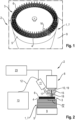
1 in einer perspektivischen Ansicht einen Stator zur Bearbeitung mit Hilfe einer erfindungsgemäßen Vorrichtung zur Herstellung des Stators und vorgangsintegrierten Prüfung einer Laserschweißnaht, -
2 in einer Prinzipdarstellung die erfindungsgemäße Vorrichtung in einem ersten Ausführungsbeispiel, -
3 in einer Prinzipdarstellung die erfindungsgemäße Vorrichtung in einem zweiten Ausführungsbeispiel, -
4 in einer Detailansicht IV ein Segment des Stators während einem Schweißvorgang, -
5 Aufnahmen zu unterschiedlichen Zeitpunkten eines Schweißvorganges, und -
6 eine Aufnahme eines Schweißvorganges mit Schweißspritzer.
-
1 in a perspective view a stator for processing with the aid of a device according to the invention for producing the stator and process-integrated testing of a laser weld seam, -
2 in a schematic representation of the device according to the invention in a first exemplary embodiment, -
3 in a schematic representation the device according to the invention in a second exemplary embodiment, -
4 in a detailed view IV a segment of the stator during a welding process, -
5 Recordings at different times of a welding process, and -
6 a recording of a welding process with weld spatter.
In
Der Stator 1 weist eine Wicklung 3 auf, welche aus so genannten Hairpins 4 ausgebildet ist. Diese Hairpins 4 sind an ihren von einem Statorboden 5 des Stators 1 abgewandt ausgebildeten Enden 6 zu verschweißen, wobei jeweils zwei Enden 6 zu einem Endpaar 21 auch als Pin bezeichnet zumit Hilfe einer Laserschweißnaht 20 einander kontaktierend verschweißt werden. Mit Hilfe der Vorrichtung 2 kann während einem Schweißvorgang eine Güte der Laserschweißnaht 20, welche in Form einer Schweißperle ausgebildet ist, bestimmt werden. Mit anderen Worten gesagt, erfolgt eine Prüfung der Laserschweißnaht 20 während dem Herstellungsvorgang des Stators 1 so dass eine Herstellung der Stators 1 und eine im Herstellungsvorgang vorgangsintegrierte Prüfung der Laserschweißnaht 20 ausgebildet ist.The stator 1 has a winding 3, which is formed from so-called
In den
Die Laserschweißeinrichtung 8 umfasst einen Träger 9 zur gesicherten Aufnahme des Stators 1. Der Stator 1 ist mit der Wicklung 3 derart relativ zu einer Laseroptik 19 der Laserschweißeinrichtung 8 orientiert, dass die Enden 6 im Betreib der Laserschweißeinrichtung 8 einem Laser 10 der Laserschweißeinrichtung 8 zugewandt angeordnet sind.The
Die Vorrichtung 2 umfasst eine Aufnahmeeinrichtung 11 in Form einer Hochgeschwindigkeitskamera zur Aufnahme von 3000 bis 15000 Bildern pro Sekunde zur visuellen Erfassung des Schweißvorganges. Die Aufnahmeeinrichtung 11 ist bevorzugt an einem Achsportal 23 der Laserschweißeinrichtung 8 aufgenommen. Die Aufnahmeeinrichtung 11 ist in der Vorrichtung 2 gemäß
Jedes Hairpin 4 besitzt zwei Enden 6, wobei jeweils zwei Enden 6 der Hairpins 4 zu einem Endpaar 21 zur Herbeiführung einer geschlossenen Wicklung 3 mit Hilfe des Lasers 10 laserverschweißt werden. Die Verschweißung der Enden 6 erfolgt über einem Umfang des Stators 1 segmentweise, wobei jeweils zwei Enden 6 zu einem Endpaar 21 verschweißt werden und das Segment 16 nach erfolgter Verschweißung bevorzugt zwischen einem und fünf Endpaaren 21, insbesondere zwischen einem und drei Endpaare 21 aufweist. Das heißt mit anderen Worten, dass nicht sämtliche Enden 6 gleichzeitig verschweißt werden, sondern es werden bevorzugt zwischen einer und drei Nuten 14 der Hairpins 4 in einer Laserposition des Lasers 10 mit Hilfe der Verschweißung zumindest teilweise geschlossen. Der Schweißvorgang eines Endpaares 21, oder mit anderen Worten das Schließen einer Nut 14 mit Hilfe der Laserschweißnaht benötigt ca. 50-150ms.Each
Während der Verschweißung der Enden 6 bewegt sich der Laser 10, bevorzugt computergesteuert, über eine so genannte Schweißbahn, wobei er in einer Position der Schweißbahn, welche selbstredend eine Mehrzahl von Positionen des Lasers 10 besitzt, bevorzugt die ein bis drei Nuten 14 erfasst. Das heißt mit anderen Worten, dass der Laser 10 zur Verschweißung der Enden 6, wobei jeweils zwei Enden 6 miteinander verschweißt werden, in zeitlicher Abfolge unterschiedliche Positionen einnimmt, wobei er in jeder Position ein bestimmtes Segment 16 des Stators 1, welches die ein bis drei Nuten 14 aufweist, erfasst.During the welding of the
In
Die Aufnahme der Bilder erfolgt mit einer Aufnahmefrequenz von 3000 bis 15000 Bildern pro Sekunde, wobei ein bevorzugter Bereich 5000 bis 10000 Bilder pro Sekunde ist. Um diese hohe Aufnahmefrequenz umsetzen zu können, ist eine bevorzugte Belichtung 15 notwendig. Die Belichtung 15 ist als monochromatische Belichtung, bevorzugt aufweisend eine Wellenlänge mit einem Wert von ca. 500nm, ausgebildet.The images are recorded at a recording frequency of 3,000 to 15,000 images per second, with a preferred range being 5,000 to 10,000 images per second. In order to be able to implement this high recording frequency, a
Eine Optik der Aufnahmeeinrichtung 11 weist einen nicht näher abgebildeten Filter in Form eines Bandpassfilters auf, welcher bevorzugt ausschließlich oder nahezu ausschließlich Licht der Belichtung 15 durchlässt, in einem bevorzugten Wellenlängenbereich von beispielsweise 500nm +/-20nm.An optics of the
Die Vorrichtung 2 des ersten Ausführungsbeispiels, wie sie in
Mit Hilfe der erfindungsgemäßen Vorrichtung 2 können die aufgenommenen Bilder in einem mit der Aufnahmeeinrichtung 11 zur Datenübertragung verbundenen Arbeitsspeicher, welcher auch unmittelbar in der Aufnahmeeinrichtung 11 angeordnet sein kann, gespeichert werden und während des Schweißvorganges, somit während der Herstellung des Stators 1 ausgewertet werden, wobei unmittelbar nach Beendigung des Schweißvorganges des Segmentes 16 eine in den Herstellungsverlauf des Stators 1 vorgangsintegrierte Prüfung der Laserschweißnaht 20 durchgeführt wird. Das heißt mit anderen Worten, dass direkt anschließend an den Schweißvorgang des Segmentes 16 die vorgangsintegrierte Prüfung der Laserschweißnaht 20 durchgeführt wird, wobei bereits das nächste Segment 16 sich im Schweißvorgang befindet.With the help of the
Unmittelbar nach dem Verschweißen des Segments 16 werden die gestapelt abgelegten Bilder, welche in Form von computerverarbeitbaren Daten vorliegen, heruntergeladen und werden unmittelbar verarbeitet. Zur Erfassung der Güte der Laserschweißnaht 20 werden folgende Parameter herangezogen:
- - Anzahl von Schweißspritzer 22, beispielsweise unterteilt in zwei Kategorien mit jeweils einem Größenbereich einer Größe des Schweißspritzers 22, beispielsweise kleine Schweißspritzer 22 mit einer Größe, die in einem ersten Größenbereich liegt, und große Schweißspritzer 22 mit einer Größe, welche in einem zweiten Größenbereich liegt,
- - Durchmesser und Zeitpunkt, jeweils quantifiziert, eines definierten als groß definierten Schweißspritzers 22,
- - Rauch
- - Größe eines so genannten Keyholes über die Zeit.
- - Number of welding spatters 22, for example divided into two categories, each with a size range of a size of the welding spatter 22, for example small welding spatters 22 with a size that is in a first size range, and large welding spatters 22 with a size that is in a second size range ,
- - Diameter and time, each quantified, of a weld spatter 22 defined as large,
- - Smoke
- - Size of a so-called keyhole over time.
Ein Schweißspritzer 22 ist in
Ein weiterer Parameter kann die realisierte Laserschweißbahn selbst sein, welche ebenfalls erfasst ist, im Vergleich zur programmierten Laserschweißbahn, so dass hier eine so genannte Vorgangskontrolle realisiert werden kann.Another parameter can be the realized laser welding path itself, which is also recorded in comparison to the programmed laser welding path, so that a so-called process control can be implemented here.
Die Prüfung der Güte der Laserschweißnaht 20 erfolgt insbesondere durch Auswertung von Grauwerten der Bilder. Dies geschieht in verschiedenen Bildbereichen. Zusätzlich werden Ereignisse im Ereigniszeitraum durch Übereinanderlegen der Bilder und anschließendes Betrachten der Grauwerte ausgewertet. In
In
Mit Hilfe der erfindungsgemäßen Vorrichtung 2 können insbesondere auffällige Laserschweißnähte 20, oder mit anderen Worten, Laserschweißnähte 20, deren Parameter Werte aufweisen, die von Grenzwerten der oben genannten Parameter abweichen, bereits während des Schweißvorganges erkannt und nach einem so genannten Schweißdurchlauf in eine Nachkontrolle, die beispielsweise mit Hilfe eines Computertomographen (CT) durchgeführt wird, geführt werden. So ist es möglich gezielt, und damit kostengünstig, auffällige Laserschweißnähte e 20 im CT oder anderen Prüfeinrichtungen nachzuprüfen.With the help of the
ZITATE ENTHALTEN IN DER BESCHREIBUNGQUOTES INCLUDED IN THE DESCRIPTION
Diese Liste der vom Anmelder aufgeführten Dokumente wurde automatisiert erzeugt und ist ausschließlich zur besseren Information des Lesers aufgenommen. Die Liste ist nicht Bestandteil der deutschen Patent- bzw. Gebrauchsmusteranmeldung. Das DPMA übernimmt keinerlei Haftung für etwaige Fehler oder Auslassungen.This list of documents listed by the applicant was generated automatically and is included solely for the better information of the reader. The list is not part of the German patent or utility model application. The DPMA assumes no liability for any errors or omissions.
Zitierte PatentliteraturCited patent literature
- DE 112010003406 B4 [0002]DE 112010003406 B4 [0002]
- DE 102014107716 B3 [0003]DE 102014107716 B3 [0003]
- JP 2004066267 A [0004]JP 2004066267 A [0004]
- JP 2017060968 A [0004]JP 2017060968 A [0004]
- WO 2008/028580 A1 [0005]WO 2008/028580 A1 [0005]
- JP 2015126660 A [0007]JP 2015126660 A [0007]
Claims (7)
Priority Applications (1)
| Application Number | Priority Date | Filing Date | Title |
|---|---|---|---|
| DE102022106788.2A DE102022106788A1 (en) | 2022-03-23 | 2022-03-23 | Device for producing a stator and process-integrated testing of a laser weld seam |
Applications Claiming Priority (1)
| Application Number | Priority Date | Filing Date | Title |
|---|---|---|---|
| DE102022106788.2A DE102022106788A1 (en) | 2022-03-23 | 2022-03-23 | Device for producing a stator and process-integrated testing of a laser weld seam |
Publications (1)
| Publication Number | Publication Date |
|---|---|
| DE102022106788A1 true DE102022106788A1 (en) | 2023-09-28 |
Family
ID=87930645
Family Applications (1)
| Application Number | Title | Priority Date | Filing Date |
|---|---|---|---|
| DE102022106788.2A Pending DE102022106788A1 (en) | 2022-03-23 | 2022-03-23 | Device for producing a stator and process-integrated testing of a laser weld seam |
Country Status (1)
| Country | Link |
|---|---|
| DE (1) | DE102022106788A1 (en) |
Cited By (1)
| Publication number | Priority date | Publication date | Assignee | Title |
|---|---|---|---|---|
| CN119237984A (en) * | 2024-12-05 | 2025-01-03 | 大连豪森瑞德设备制造有限公司 | A visual inspection system for X-pin stator after welding |
Citations (8)
| Publication number | Priority date | Publication date | Assignee | Title |
|---|---|---|---|---|
| JP2004066267A (en) | 2002-08-02 | 2004-03-04 | Toyota Motor Corp | Laser welding quality inspection method and apparatus |
| WO2008028580A1 (en) | 2006-09-06 | 2008-03-13 | Precitec Vision Gmbh & Co. Kg | Method and device for the optical assessment of welding quality during welding |
| DE102014107716B3 (en) | 2014-06-02 | 2015-06-25 | Scansonic Mi Gmbh | Laser beam welding process |
| JP2015126660A (en) | 2013-12-27 | 2015-07-06 | トヨタ自動車株式会社 | Welding quality inspection apparatus, and welding quality inspection method |
| JP2016107318A (en) | 2014-12-09 | 2016-06-20 | 日立造船株式会社 | Laser welding device having bevel part monitor and bevel part monitoring method of laser welding device |
| JP2017060968A (en) | 2015-09-25 | 2017-03-30 | 株式会社Nishihara | Image processing apparatus, image processing method, laser or TIG welding apparatus, and laser or TIG welding apparatus control method |
| DE112010003406B4 (en) | 2009-08-27 | 2021-05-06 | Ihi Inspection & Instrumentation Co., Ltd. | Laser welding quality determination method and device |
| US20220048137A1 (en) | 2020-08-14 | 2022-02-17 | Corelase Oy | Laser welding of metal pin pairs with time-dependent scan pattern and energy input |
-
2022
- 2022-03-23 DE DE102022106788.2A patent/DE102022106788A1/en active Pending
Patent Citations (8)
| Publication number | Priority date | Publication date | Assignee | Title |
|---|---|---|---|---|
| JP2004066267A (en) | 2002-08-02 | 2004-03-04 | Toyota Motor Corp | Laser welding quality inspection method and apparatus |
| WO2008028580A1 (en) | 2006-09-06 | 2008-03-13 | Precitec Vision Gmbh & Co. Kg | Method and device for the optical assessment of welding quality during welding |
| DE112010003406B4 (en) | 2009-08-27 | 2021-05-06 | Ihi Inspection & Instrumentation Co., Ltd. | Laser welding quality determination method and device |
| JP2015126660A (en) | 2013-12-27 | 2015-07-06 | トヨタ自動車株式会社 | Welding quality inspection apparatus, and welding quality inspection method |
| DE102014107716B3 (en) | 2014-06-02 | 2015-06-25 | Scansonic Mi Gmbh | Laser beam welding process |
| JP2016107318A (en) | 2014-12-09 | 2016-06-20 | 日立造船株式会社 | Laser welding device having bevel part monitor and bevel part monitoring method of laser welding device |
| JP2017060968A (en) | 2015-09-25 | 2017-03-30 | 株式会社Nishihara | Image processing apparatus, image processing method, laser or TIG welding apparatus, and laser or TIG welding apparatus control method |
| US20220048137A1 (en) | 2020-08-14 | 2022-02-17 | Corelase Oy | Laser welding of metal pin pairs with time-dependent scan pattern and energy input |
Cited By (1)
| Publication number | Priority date | Publication date | Assignee | Title |
|---|---|---|---|---|
| CN119237984A (en) * | 2024-12-05 | 2025-01-03 | 大连豪森瑞德设备制造有限公司 | A visual inspection system for X-pin stator after welding |
Similar Documents
| Publication | Publication Date | Title |
|---|---|---|
| EP3076148B1 (en) | Device and method for measuring imaging properties of an optical imaging system | |
| DE102015118874A1 (en) | Method for operating a sensor system of a motor vehicle, driver assistance system and system for calibrating a sensor system of a motor vehicle | |
| EP3961559A1 (en) | Method and device for detecting defects during surface modification method | |
| EP4288932B1 (en) | Method and device for evaluating a weld quality of a weld joint between end sections of two conductor elements | |
| DE102016214227B3 (en) | Apparatus and method for producing a tested welded joint | |
| DE102007053993A1 (en) | Method and device for tool measurement | |
| DE102008027393A1 (en) | Optical monitoring device | |
| DE102015001922A1 (en) | A method of determining a quality of a joining operation and apparatus for determining a quality of a joining operation | |
| DE102014104581A1 (en) | Method for monitoring a tool, method for assessing the quality of a machined surface of a workpiece and apparatus for performing the method | |
| DE102024001048A1 (en) | Method for assessing a weld seam produced on a workpiece during a laser welding process using a laser beam and welding device for carrying out the method | |
| DE102022106788A1 (en) | Device for producing a stator and process-integrated testing of a laser weld seam | |
| DE102020120103A1 (en) | Method for checking the position of a wheel on a vehicle, and checking system | |
| EP4540014A1 (en) | System and method for error control of laser welding processes | |
| DE102023103439A1 (en) | Computer-aided procedure | |
| DE102021209993B4 (en) | Method for determining the quality of a laser beam weld | |
| DE102019132156A1 (en) | Method for connecting shaped bars and components | |
| EP3959094B1 (en) | Method and system for producing a seal | |
| EP4194184B1 (en) | Welding assessment during the welding process | |
| EP4078463A2 (en) | Method for determining and correcting the machine state of a machine tool, and diagnostic system | |
| DE102016218308B4 (en) | Apparatus and method for producing a tested welded joint | |
| DE102016005949A1 (en) | Method for cleaning and checking the technical cleanliness of a drive train surface | |
| DE102023004313A1 (en) | Method and welding system for producing a welded joint | |
| DE102022106769A1 (en) | Method for checking the condition of at least two areas of an object | |
| EP0788851A2 (en) | Method and device for inspecting a drawing die | |
| DE102022203837A1 (en) | Method for monitoring a laser welding process, device for carrying out the same and its use |
Legal Events
| Date | Code | Title | Description |
|---|---|---|---|
| R012 | Request for examination validly filed | ||
| R016 | Response to examination communication |