DE102022003153B3 - Planetary gear, especially for a motor vehicle - Google Patents
Planetary gear, especially for a motor vehicle Download PDFInfo
- Publication number
- DE102022003153B3 DE102022003153B3 DE102022003153.1A DE102022003153A DE102022003153B3 DE 102022003153 B3 DE102022003153 B3 DE 102022003153B3 DE 102022003153 A DE102022003153 A DE 102022003153A DE 102022003153 B3 DE102022003153 B3 DE 102022003153B3
- Authority
- DE
- Germany
- Prior art keywords
- planetary gear
- lubricant
- rotation axis
- planet
- channel
- Prior art date
- Legal status (The legal status is an assumption and is not a legal conclusion. Google has not performed a legal analysis and makes no representation as to the accuracy of the status listed.)
- Active
Links
Images

Classifications
-
- F—MECHANICAL ENGINEERING; LIGHTING; HEATING; WEAPONS; BLASTING
- F16—ENGINEERING ELEMENTS AND UNITS; GENERAL MEASURES FOR PRODUCING AND MAINTAINING EFFECTIVE FUNCTIONING OF MACHINES OR INSTALLATIONS; THERMAL INSULATION IN GENERAL
- F16H—GEARING
- F16H57/00—General details of gearing
- F16H57/04—Features relating to lubrication or cooling or heating
- F16H57/048—Type of gearings to be lubricated, cooled or heated
- F16H57/0482—Gearings with gears having orbital motion
- F16H57/0484—Gearings with gears having orbital motion with variable gear ratio or for reversing rotary motion
-
- B—PERFORMING OPERATIONS; TRANSPORTING
- B60—VEHICLES IN GENERAL
- B60T—VEHICLE BRAKE CONTROL SYSTEMS OR PARTS THEREOF; BRAKE CONTROL SYSTEMS OR PARTS THEREOF, IN GENERAL; ARRANGEMENT OF BRAKING ELEMENTS ON VEHICLES IN GENERAL; PORTABLE DEVICES FOR PREVENTING UNWANTED MOVEMENT OF VEHICLES; VEHICLE MODIFICATIONS TO FACILITATE COOLING OF BRAKES
- B60T1/00—Arrangements of braking elements, i.e. of those parts where braking effect occurs specially for vehicles
- B60T1/02—Arrangements of braking elements, i.e. of those parts where braking effect occurs specially for vehicles acting by retarding wheels
- B60T1/06—Arrangements of braking elements, i.e. of those parts where braking effect occurs specially for vehicles acting by retarding wheels acting otherwise than on tread, e.g. employing rim, drum, disc, or transmission or on double wheels
- B60T1/062—Arrangements of braking elements, i.e. of those parts where braking effect occurs specially for vehicles acting by retarding wheels acting otherwise than on tread, e.g. employing rim, drum, disc, or transmission or on double wheels acting on transmission parts
-
- F—MECHANICAL ENGINEERING; LIGHTING; HEATING; WEAPONS; BLASTING
- F16—ENGINEERING ELEMENTS AND UNITS; GENERAL MEASURES FOR PRODUCING AND MAINTAINING EFFECTIVE FUNCTIONING OF MACHINES OR INSTALLATIONS; THERMAL INSULATION IN GENERAL
- F16D—COUPLINGS FOR TRANSMITTING ROTATION; CLUTCHES; BRAKES
- F16D65/00—Parts or details
- F16D65/78—Features relating to cooling
- F16D65/84—Features relating to cooling for disc brakes
- F16D65/853—Features relating to cooling for disc brakes with closed cooling system
-
- F—MECHANICAL ENGINEERING; LIGHTING; HEATING; WEAPONS; BLASTING
- F16—ENGINEERING ELEMENTS AND UNITS; GENERAL MEASURES FOR PRODUCING AND MAINTAINING EFFECTIVE FUNCTIONING OF MACHINES OR INSTALLATIONS; THERMAL INSULATION IN GENERAL
- F16H—GEARING
- F16H57/00—General details of gearing
- F16H57/04—Features relating to lubrication or cooling or heating
- F16H57/042—Guidance of lubricant
- F16H57/0421—Guidance of lubricant on or within the casing, e.g. shields or baffles for collecting lubricant, tubes, pipes, grooves, channels or the like
- F16H57/0423—Lubricant guiding means mounted or supported on the casing, e.g. shields or baffles for collecting lubricant, tubes or pipes
-
- F—MECHANICAL ENGINEERING; LIGHTING; HEATING; WEAPONS; BLASTING
- F16—ENGINEERING ELEMENTS AND UNITS; GENERAL MEASURES FOR PRODUCING AND MAINTAINING EFFECTIVE FUNCTIONING OF MACHINES OR INSTALLATIONS; THERMAL INSULATION IN GENERAL
- F16H—GEARING
- F16H57/00—General details of gearing
- F16H57/04—Features relating to lubrication or cooling or heating
- F16H57/042—Guidance of lubricant
- F16H57/0427—Guidance of lubricant on rotary parts, e.g. using baffles for collecting lubricant by centrifugal force
-
- F—MECHANICAL ENGINEERING; LIGHTING; HEATING; WEAPONS; BLASTING
- F16—ENGINEERING ELEMENTS AND UNITS; GENERAL MEASURES FOR PRODUCING AND MAINTAINING EFFECTIVE FUNCTIONING OF MACHINES OR INSTALLATIONS; THERMAL INSULATION IN GENERAL
- F16H—GEARING
- F16H57/00—General details of gearing
- F16H57/04—Features relating to lubrication or cooling or heating
- F16H57/042—Guidance of lubricant
- F16H57/043—Guidance of lubricant within rotary parts, e.g. axial channels or radial openings in shafts
-
- F—MECHANICAL ENGINEERING; LIGHTING; HEATING; WEAPONS; BLASTING
- F16—ENGINEERING ELEMENTS AND UNITS; GENERAL MEASURES FOR PRODUCING AND MAINTAINING EFFECTIVE FUNCTIONING OF MACHINES OR INSTALLATIONS; THERMAL INSULATION IN GENERAL
- F16H—GEARING
- F16H57/00—General details of gearing
- F16H57/04—Features relating to lubrication or cooling or heating
- F16H57/0467—Elements of gearings to be lubricated, cooled or heated
- F16H57/0469—Bearings or seals
- F16H57/0471—Bearing
-
- F—MECHANICAL ENGINEERING; LIGHTING; HEATING; WEAPONS; BLASTING
- F16—ENGINEERING ELEMENTS AND UNITS; GENERAL MEASURES FOR PRODUCING AND MAINTAINING EFFECTIVE FUNCTIONING OF MACHINES OR INSTALLATIONS; THERMAL INSULATION IN GENERAL
- F16H—GEARING
- F16H57/00—General details of gearing
- F16H57/04—Features relating to lubrication or cooling or heating
- F16H57/0467—Elements of gearings to be lubricated, cooled or heated
- F16H57/0473—Friction devices, e.g. clutches or brakes
-
- F—MECHANICAL ENGINEERING; LIGHTING; HEATING; WEAPONS; BLASTING
- F16—ENGINEERING ELEMENTS AND UNITS; GENERAL MEASURES FOR PRODUCING AND MAINTAINING EFFECTIVE FUNCTIONING OF MACHINES OR INSTALLATIONS; THERMAL INSULATION IN GENERAL
- F16H—GEARING
- F16H57/00—General details of gearing
- F16H57/04—Features relating to lubrication or cooling or heating
- F16H57/0467—Elements of gearings to be lubricated, cooled or heated
- F16H57/0479—Gears or bearings on planet carriers
-
- F—MECHANICAL ENGINEERING; LIGHTING; HEATING; WEAPONS; BLASTING
- F16—ENGINEERING ELEMENTS AND UNITS; GENERAL MEASURES FOR PRODUCING AND MAINTAINING EFFECTIVE FUNCTIONING OF MACHINES OR INSTALLATIONS; THERMAL INSULATION IN GENERAL
- F16H—GEARING
- F16H57/00—General details of gearing
- F16H57/08—General details of gearing of gearings with members having orbital motion
- F16H57/10—Braking arrangements
-
- F—MECHANICAL ENGINEERING; LIGHTING; HEATING; WEAPONS; BLASTING
- F16—ENGINEERING ELEMENTS AND UNITS; GENERAL MEASURES FOR PRODUCING AND MAINTAINING EFFECTIVE FUNCTIONING OF MACHINES OR INSTALLATIONS; THERMAL INSULATION IN GENERAL
- F16D—COUPLINGS FOR TRANSMITTING ROTATION; CLUTCHES; BRAKES
- F16D13/00—Friction clutches
- F16D13/58—Details
- F16D13/60—Clutching elements
- F16D13/64—Clutch-plates; Clutch-lamellae
- F16D13/648—Clutch-plates; Clutch-lamellae for clutches with multiple lamellae
-
- F—MECHANICAL ENGINEERING; LIGHTING; HEATING; WEAPONS; BLASTING
- F16—ENGINEERING ELEMENTS AND UNITS; GENERAL MEASURES FOR PRODUCING AND MAINTAINING EFFECTIVE FUNCTIONING OF MACHINES OR INSTALLATIONS; THERMAL INSULATION IN GENERAL
- F16D—COUPLINGS FOR TRANSMITTING ROTATION; CLUTCHES; BRAKES
- F16D13/00—Friction clutches
- F16D13/58—Details
- F16D13/74—Features relating to lubrication
-
- F—MECHANICAL ENGINEERING; LIGHTING; HEATING; WEAPONS; BLASTING
- F16—ENGINEERING ELEMENTS AND UNITS; GENERAL MEASURES FOR PRODUCING AND MAINTAINING EFFECTIVE FUNCTIONING OF MACHINES OR INSTALLATIONS; THERMAL INSULATION IN GENERAL
- F16H—GEARING
- F16H57/00—General details of gearing
- F16H57/02—Gearboxes; Mounting gearing therein
- F16H2057/02039—Gearboxes for particular applications
- F16H2057/02043—Gearboxes for particular applications for vehicle transmissions
- F16H2057/02047—Automatic transmissions
-
- F—MECHANICAL ENGINEERING; LIGHTING; HEATING; WEAPONS; BLASTING
- F16—ENGINEERING ELEMENTS AND UNITS; GENERAL MEASURES FOR PRODUCING AND MAINTAINING EFFECTIVE FUNCTIONING OF MACHINES OR INSTALLATIONS; THERMAL INSULATION IN GENERAL
- F16H—GEARING
- F16H57/00—General details of gearing
- F16H57/08—General details of gearing of gearings with members having orbital motion
- F16H2057/087—Arrangement and support of friction devices in planetary gearings, e.g. support of clutch drums, stacked arrangements of friction devices
Landscapes
- Engineering & Computer Science (AREA)
- General Engineering & Computer Science (AREA)
- Mechanical Engineering (AREA)
- Transportation (AREA)
- General Details Of Gearings (AREA)
Abstract
Die Erfindung betrifft ein Planetengetriebe (10), mit einer Fangrinne (12) für ein Schmiermittel, mit einem Planetenradsatz (28), welcher zumindest einen um eine Planetenradsatzdrehachse (92) relativ zu einem Gehäuse (32) des Planetengetriebes (10) drehbaren Planetenträger (30), drehbar an dem Planetenträger (30) gelagerte Planetenräder (34) sowie ein mit den Planetenrädern (34) kämmendes Hohlrad (38) aufweist, und mit einer Lamellenkupplung (39), welche einen drehfest mit der Fangrinne (12) verbundenen Innenlamellenträger (40), einen drehfest mit dem Gehäuse (32) des Planetengetriebes (10) verbundenen Außenlamellenträger (42) sowie einen Satz (44) von Reiblamellen (46, 48) aufweist, wobei der Innenlamellenträger (40) drehfest mit dem Hohlrad (38) verbunden ist, wobei das Hohlrad (38) und/oder ein drehfest mit dem Hohlrad (38) verbundener Zylinderabschnitt (54) einen hinsichtlich der Planetenradsatzdrehachse (92) des Planetengetriebes (10) radial verlaufenden, ersten Schmiermittelkanal (56) aufweist.

Description
Die Erfindung betrifft ein Planetengetriebe, insbesondere für ein Kraftfahrzeug, das heißt insbesondere für einen Antriebsstrang eines Kraftfahrzeugs, gemäß dem Oberbegriff von Patentanspruch 1.The invention relates to a planetary gear, in particular for a motor vehicle, that is in particular for a drive train of a motor vehicle, according to the preamble of patent claim 1.
Der
Die
Aufgabe der vorliegenden Erfindung ist es, ein Planetengetriebe, insbesondere für ein Kraftfahrzeug, zu schaffen, sodass eine besonders vorteilhafte Schmiermittelversorgung realisiert werden kann.The object of the present invention is to create a planetary gear, in particular for a motor vehicle, so that a particularly advantageous lubricant supply can be realized.
Diese Aufgabe wird durch ein Planetengetriebe mit den Merkmalen des Patentanspruchs 1 gelöst. Vorteilhafte Ausgestaltungen mit zweckmäßigen Weiterbildungen der Erfindung sind in den übrigen Ansprüchen angegeben.This task is solved by a planetary gear with the features of patent claim 1. Advantageous embodiments with useful developments of the invention are specified in the remaining claims.
Die Erfindung betrifft ein Planetengetriebe, insbesondere für ein Kraftfahrzeug und ganz insbesondere für einen Antriebsstrang eines Kraftfahrzeugs. Dies bedeutet beispielsweise, dass das einfach auch als Fahrzeug bezeichnete und beispielsweise als Kraftwagen, insbesondere als Personenkraftwagen, ausgebildete Kraftfahrzeug in seinem vollständig hergestellten Zustand das Planetengetriebe aufweist, Insbesondere weist das Kraftfahrzeug den genannten Antriebsstrang auf, mittels welchem das Kraftfahrzeug antreibbar ist. Der Antriebsstrang umfasst dabei das Planetengetriebe. Beispielsweise sind Fahrzeugräder des Kraftfahrzeugs über das Planetengetriebe von einer Antriebseinrichtung des Kraftfahrzeugs antreibbar. Hierdurch kann das Kraftfahrzeug insgesamt angetrieben werden. Die Antriebseinrichtung ist oder umfasst eine elektrische Maschine. Alternativ oder zusätzlich ist oder umfasst die Antriebseinrichtung beispielsweise einen Verbrennungsmotor.The invention relates to a planetary gear, in particular for a motor vehicle and especially for a drive train of a motor vehicle. This means, for example, that the motor vehicle, which is also simply referred to as a vehicle and is designed, for example, as a motor vehicle, in particular as a passenger car, has the planetary gear in its fully manufactured state. In particular, the motor vehicle has the drive train mentioned, by means of which the motor vehicle can be driven. The drive train includes the planetary gear. For example, vehicle wheels of the motor vehicle can be driven by a drive device of the motor vehicle via the planetary gear. This allows the motor vehicle as a whole to be driven. The drive device is or includes an electrical machine. Alternatively or additionally, the drive device is or includes, for example, an internal combustion engine.
Das Planetengetriebe weist eine Fangrinne für ein Schmiermittel auf. Die Fangrinne wird auch als erste Fangrinne bezeichnet. Wenn im Folgenden die Rede von der Fangrinne ist, so ist darunter, falls nichts anderes angegeben ist, die erste Fangrinne zu verstehen. Die Fangrinne ist ein Fangelement, mittels welchem das vorzugsweise flüssige Schmiermittel, welches beispielsweise als ein Öl ausgebildet ist, auffangbar und beispielsweise danach gezielt zu führen oder zu leiten ist. Insbesondere weist beispielsweise die Fangrinne eine gewölbte, insbesondere konkave, Oberfläche auf, die beispielsweise einem von dem Schmiermittel durchströmbaren Austritt zugewandt ist, über welchen das Schmiermittel bereitstellbar ist. Insbesondere ist das vorzugsweise flüssige Schmiermittel aus dem Austritt ausspritzbar und somit über den Austritt bereitstellbar. Das den Austritt durchströmende, insbesondere aus dem Austritt ausgespritzte, Schmiermittel kann gegen die Fangrinne, insbesondere gegen die genannte, als Fangfläche fungierende Oberfläche, strömen und somit durch die Oberfläche aufgefangen werden, woraufhin beispielsweise das mittels der Fangrinne, insbesondere mittels der Oberfläche, aufgefangene Schmiermittel mittels der Fangrinne gezielt zu wenigstens einer Stelle, insbesondere der Schmierstelle, geführt werden kann. An der Stelle kann das Schmiermittel beispielsweise wenigstens zwei relativ zueinander bewegbare Bauelemente schmieren und/oder kühlen.The planetary gear has a collecting channel for a lubricant. The gutter is also referred to as the first gutter. When we talk about the gutter below, this refers to the first gutter unless otherwise stated. The collecting channel is a catching element by means of which the preferably liquid lubricant, which is designed, for example, as an oil, can be collected and, for example, can then be guided or guided in a targeted manner. In particular, for example, the collecting channel has a curved, in particular concave, surface, which faces, for example, an outlet through which the lubricant can flow, via which the lubricant can be provided. In particular, the preferably liquid lubricant can be sprayed out of the outlet and thus made available via the outlet. The lubricant flowing through the outlet, in particular sprayed out of the outlet, can flow against the collecting trough, in particular against the surface mentioned, which acts as a collecting surface, and can thus be collected by the surface, whereupon, for example, the lubricant collected by means of the collecting trough, in particular by means of the surface can be guided specifically to at least one point, in particular the lubrication point, by means of the collecting channel. At this point, the lubricant can, for example, lubricate and/or cool at least two components that can be moved relative to one another.
Das Planetengetriebe weist einen Planetenradsatz auf, welcher auch einfach als Planetensatz bezeichnet wird. Der Planetenradsatz weist zumindest einen auch als Steg bezeichneten Planetenträger auf, welcher um eine Planetenradsatzdrehachse relativ zu einem Gehäuse des Planetengetriebes drehbar ist. Beispielsweise ist der Planetenträger zumindest teilweise in dem Gehäuse angeordnet. Der Planetenradsatz weist auch Planetenräder auf, welche drehbar an dem Planetenträger gelagert sind. Insbesondere ist das jeweilige Planetenrad um eine jeweilige Planetenraddrehachse relativ zu dem Planetenträger drehbar an dem Planetenträger gehalten. Dabei ist es beispielsweise vorgesehen, dass die jeweilige Planetenraddrehachse parallel zur Planetenradsatzdrehachse verläuft und von der Planetenradsatzdrehachse beabstandet ist. Insbesondere ist denkbar, dass die Planetenraddrehachsen insbesondere in um die Planetenradsatzdrehachse verlaufender Umfangsrichtung des Planetenradsatzes voneinander beabstandet sind. Insbesondere sind die Planetenraddrehachsen auf einem gemeinsamen Kreis angeordnet, dessen Mittelpunkt beispielsweise auf der Planetenradsatzdrehachse liegt. Der Planetenradsatz weist auch ein Hohlrad auf, welches mit den Planetenrädern kämmt. Insbesondere ist das Hohlrad um die Planetenradsatzdrehachse relativ zu dem Gehäuse des Planetengetriebes drehbar. Beispielsweise ist das Hohlrad zumindest teilweise im Gehäuse angeordnet. Insbesondere ist denkbar, dass die Planetenräder zumindest teilweise in dem Gehäuse angeordnet sind.The planetary gear has a planetary gear set, which is also simply referred to as a planetary gear set. The planetary gear set has at least one planet carrier, also referred to as a web, which is rotatable about a planetary gear set rotation axis relative to a housing of the planetary gear. For example, the planet carrier is at least partially arranged in the housing. The planetary gear set also has planet gears which are rotatably mounted on the planet carrier. In particular, the respective planet gear is held on the planet carrier so that it can rotate relative to the planet carrier about a respective planet wheel rotation axis. It is provided, for example, that the respective planetary gear rotation axis runs parallel to the planetary gear set rotation axis and is spaced from the planetary gear set rotation axis. In particular, it is conceivable that the planetary gear rotation axes are spaced apart from one another, in particular in the circumferential direction of the planetary gearset that runs around the planetary gearset rotation axis. In particular, the planetary gear rotation axes are arranged on a common circle, the center of which lies, for example, on the planetary gear rotation axis. The planetary gear set also has a ring gear which meshes with the planetary gears. In particular, the ring gear is rotatable about the planetary gear set rotation axis relative to the housing of the planetary gear. For example, the ring gear is at least partially arranged in the housing. In particular, it is conceivable that the planet gears are at least partially arranged in the housing.
Das Planetengetriebe weist auch eine Lamellenkupplung auf, welche einen drehfest mit der Fangrinne verbundenen Innenlamellenträger aufweist. Die Lamellenkupplung weist einen Außenlamellenträger auf, welcher, insbesondere permanent, drehfest mit dem Gehäuse verbunden ist. Des Weiteren weist die Lamellenkupplung einen Satz von Reiblamellen auf. Beispielsweise sind erste der Reiblamellen Innenlamellen, die an dem Innenlamellenträger gehalten und somit durch den Innenlamellenträger gehalten sind. Insbesondere sind die Innenlamellen in um die Planetenradsatzdrehachse verlaufender Umfangsrichtung des Planetenradsatzes an dem Innenlamellenträger abstützbar oder abgestützt, sodass in Umfangsrichtung des Planetenradsatzes verlaufende Drehmomente zwischen den Innenlamellen und dem Innenlamellenträger übertragen werden können. Somit sind die Innenlamellen drehmomentübertragend, insbesondere drehfest, mit dem Innenlamellenträger gekoppelt. Zweite der Reiblamellen sind beispielsweise Außenlamellen, welche an dem Außenlamellenträger gehalten und somit durch den Außenlamellenträger getragen sind. Insbesondere sind die Außenlamellen in um die Planetenradsatzdrehachse verlaufender Umfangsrichtung des Planetenradsatzes an dem Außenlamellenträger abstützbar oder abgestützt, sodass in Umfangsrichtung des Planetenradsatzes verlaufende Drehmomente zwischen den Außenlamellen und dem Außenlamellenträger übertragen werden können. Die Außenlamellen sind somit drehmomentübertragend mit dem Außenlamellenträger gekoppelt. Insbesondere ist denkbar, dass die Innenlamellen und die Außenlamellen insbesondere in axialer Richtung des Planetenradsatzes und somit entlang der Planetenradsatzdrehachse betrachtet abwechselnd aufeinanderfolgend angeordnet sind. Da der Außenlamellenträger, insbesondere permanent, drehfest mit dem Gehäuse verbunden ist, können der Innenlamellenträger und der Außenlamellenträger mittels der Reiblamellen drehfest miteinander verbunden werden, sodass der Innenlamellenträger über den Außenlamellenträger drehfest mit dem Gehäuse verbindbar ist. Die Reiblamellen bilden beispielsweise ein Lamellenpaket. Mit anderen Worten wird der Satz von Reiblamellen beispielsweise auch als Lamellenpaket bezeichnet.The planetary gear also has a multi-plate clutch, which is non-rotatable the inner disk carrier connected to the gutter. The multi-disc clutch has an outer disc carrier, which is connected, in particular permanently, in a rotationally fixed manner to the housing. Furthermore, the multi-plate clutch has a set of friction plates. For example, the first of the friction disks are inner disks that are held on the inner disk carrier and are thus held by the inner disk carrier. In particular, the inner disks can be supported or supported on the inner disk carrier in the circumferential direction of the planetary gear set running around the planetary gear set rotation axis, so that torques running in the circumferential direction of the planetary gear set can be transmitted between the inner disks and the inner disk carrier. The inner disks are thus coupled to the inner disk carrier in a torque-transmitting manner, in particular in a rotationally fixed manner. Second of the friction plates are, for example, outer plates, which are held on the outer plate carrier and are thus supported by the outer plate carrier. In particular, the outer disks can be supported or supported on the outer disk carrier in the circumferential direction of the planetary gear set running around the planetary gear set rotation axis, so that torques running in the circumferential direction of the planetary gear set can be transmitted between the outer disks and the outer disk carrier. The outer disks are thus coupled to the outer disk carrier in a torque-transmitting manner. In particular, it is conceivable that the inner disks and the outer disks are arranged alternately one after the other, particularly in the axial direction of the planetary gear set and thus along the axis of rotation of the planetary gear set. Since the outer disk carrier is connected to the housing in a rotationally fixed manner, in particular permanently, the inner disk carrier and the outer disk carrier can be connected to one another in a rotationally fixed manner by means of the friction disks, so that the inner disk carrier can be connected to the housing in a rotationally fixed manner via the outer disk carrier. The friction plates form, for example, a plate pack. In other words, the set of friction plates is also referred to as a plate pack, for example.
Um nun eine besonders vorteilhafte Schmiermittelversorgung, insbesondere des Lamellenpakets, realisieren zu können, ist es ferner auf bekannte Weise vorgesehen, dass der Innenlamellenträger, insbesondere permanent, drehfest mit dem Hohlrad verbunden ist, sodass der Innenlamellenträger und das Hohlrad gemeinsam beziehungsweise gleichzeitig um die Planetenradsatzdrehachse relativ zu dem Gehäuse drehbar sind. Somit kann das Hohlrad mittels der Lamellenkupplung drehfest mit dem Gehäuse verbunden werden.In order to be able to realize a particularly advantageous lubricant supply, in particular of the disk pack, it is further provided in a known manner that the inner disk carrier is connected, in particular permanently, in a rotationally fixed manner to the ring gear, so that the inner disk carrier and the ring gear together or simultaneously relative to the planetary gear set rotation axis can be rotated to the housing. The ring gear can therefore be connected to the housing in a rotationally fixed manner using the multi-plate clutch.
Des Weiteren ist auf bekannte Weise vorgesehen, dass das Hohlrad und/oder ein drehfest mit dem Hohlrad verbundener Zylinderabschnitt einen hinsichtlich der Planetenradsatzdrehachse des Planetengetriebes radial verlaufenden, ersten Schmiermittelkanal aufweist. Unter dem Merkmal, dass der gegebenenfalls vorgesehene Zylinderabschnitt drehfest mit dem Hohlrad verbunden ist, ist zu verstehen, dass der, insbesondere innenumfangsseitig und/oder außenumfangsseitig, zylinderförmige Zylinderabschnitt und das Hohlrad separat voneinander ausgebildete und, insbesondere permanent, drehfest miteinander verbundene Elemente sind, oder der Zylinderabschnitt und das Hohlrad sind aus einem einzigen Stück gebildet, mithin einstückig miteinander ausgebildet. Unter dem Merkmal, dass das Hohlrad und der Zylinderabschnitt einstückig miteinander ausgebildet sind, mithin aus einem einzigen Stück gebildet sind, ist zu verstehen, dass der Zylinderabschnitt und das Hohlrad nicht etwa aus separat voneinander ausgebildeten und miteinander verbundenen Bauteilen zusammengesetzt sind, sondern das Hohlrad und der Zylinderabschnitt sind aus einem einzigen Stück gebildet, mithin als ein Monoblock ausgebildet oder durch einen Monoblock gebildet. Unter dem Monoblock ist ein aus einem einzigen Stück gebildeter und somit integraler beziehungsweise integral hergestellter Körper zu verstehen. Unter dem Merkmal, dass der erste Schmiermittelkanal hinsichtlich der Planetenradsatzdrehachse radial verläuft, ist zu verstehen, dass der erste Schmiermittelkanal, insbesondere dessen Längserstreckungsrichtung, senkrecht zur Planetenradsatzdrehachse und somit senkrecht zur axialen Richtung des Planetengetriebes und somit in radialer Richtung des Planetengetriebes verläuft. Insbesondere ist hierunter zu verstehen, dass der beispielsweise als eine Bohrung ausgebildete und durch eine Bohrung gebildete und/oder als Durchgangsöffnung ausgebildete, erste Schmiermittelkanal entlang einer ersten Strömungsrichtung von dem vorzugsweise flüssigen Schmiermittel durchströmbar ist, wobei die erste Strömungsrichtung in radialer Richtung des Planetengetriebes, mithin senkrecht zur Planetenradsatzdrehachse und somit senkrecht zur axialen Richtung des Planetengetriebes verläuft. Insbesondere verläuft die erste Strömungsrichtung, in die der erste Schmiermittelkanal von dem Schmiermittel durchströmbar ist, in radialer Richtung des Planetengetriebes von innen nach außen. Dadurch kann eine gezielte und bedarfsgerechte Schmiermittelversorgung, insbesondere des Lamellenpakets, realisiert werden. Unter der Schmiermittelversorgung des Lamellenpakets ist eine Versorgung des Lamellenpakets mit dem Schmiermittel zu verstehen.Furthermore, it is provided in a known manner that the ring gear and/or a cylinder section non-rotatably connected to the ring gear has a first lubricant channel which extends radially with respect to the planetary gear set rotation axis of the planetary gear. The feature that the optionally provided cylinder section is connected in a rotationally fixed manner to the ring gear is to be understood as meaning that the cylindrical cylinder section, in particular on the inner circumference and/or outer circumference, and the ring gear are elements which are designed separately from one another and are, in particular permanently, connected to one another in a rotationally fixed manner, or the cylinder section and the ring gear are formed from a single piece, and are therefore formed in one piece with one another. The feature that the ring gear and the cylinder section are formed in one piece with one another, and are therefore formed from a single piece, means that the cylinder section and the ring gear are not composed of components that are designed separately from one another and are connected to one another, but rather the ring gear and the cylinder section are formed from a single piece, therefore designed as a monoblock or formed by a monoblock. The monoblock is understood to mean a body formed from a single piece and therefore integral or integrally manufactured. The feature that the first lubricant channel runs radially with respect to the planetary gear set rotation axis is to be understood as meaning that the first lubricant channel, in particular its longitudinal extension direction, runs perpendicular to the planetary gear set rotation axis and thus perpendicular to the axial direction of the planetary gear and thus in the radial direction of the planetary gear. In particular, this is to be understood as meaning that the first lubricant channel, which is designed, for example, as a bore and/or as a through opening, can be flowed through by the preferably liquid lubricant along a first flow direction, the first flow direction being in the radial direction of the planetary gear, i.e perpendicular to the planetary gear set rotation axis and thus perpendicular to the axial direction of the planetary gear. In particular, the first flow direction in which the lubricant can flow through the first lubricant channel runs in the radial direction of the planetary gear from the inside to the outside. This allows a targeted and needs-based supply of lubricant, especially to the disk pack, to be achieved. The supply of lubricant to the disk pack is understood to mean supplying the disk pack with the lubricant.
Durch die als Schmiermittelfänger, insbesondere Ölfänger, fungierende oder als Schmiermittelfänger ausgebildete Fangrinne kann ein vorteilhafter Schmiermittelstrom des Schmiermittels gefangen und bewirkt werden, um die einfach auch als Lamellen bezeichneten Reiblamellen gezielt mit dem Schmiermittel zu versorgen, insbesondere zu beölen. Insbesondere ist es möglich, den Schmiermittelstrom dem Lamellenpaket bedarfsgerecht zuzuführen, insbesondere über den genannten Austritt. Durch diese bedarfsgerechte Schmiermittelversorgung können Verluste besonders geringgehalten werden, sodass ein besonders effizienter Betrieb darstellbar ist.Through the collecting trough, which functions as a lubricant catcher, in particular an oil catcher, or is designed as a lubricant catcher, an advantageous lubricant flow of the lubricant can be caught and effected in order to selectively connect the friction plates, which are also simply referred to as plates To supply lubricants, especially to oil. In particular, it is possible to supply the lubricant flow to the disk pack as required, in particular via the outlet mentioned. This needs-based supply of lubricant allows losses to be kept particularly low, so that particularly efficient operation can be achieved.
Im Rahmen der vorliegenden Offenbarung beziehen sich die Begriffe „axial“ und „radial“, wenn nichts anderes angegeben ist, auf die Planetenradsatzdrehachse des Planetengetriebes, wobei der Planetenträger, das Hohlrad, der Innenlamellenträger und der Außenlamellenträger koaxial zueinander beziehungsweise koaxial zu der Planetenradsatzdrehachse angeordnet sind. Der Innenlamellenträger und der Außenlamellenträger werden zusammenfassend als Lamellenträger bezeichnet. Im Rahmen der vorliegenden Offenbarung ist unter dem Begriff „radial innerhalb“ Folgendes zu verstehen: Ein insbesondere drehbar gelagertes, erstes Element ist radial innerhalb eines anderen, zweiten, insbesondere drehbar gelagerten, Elements angeordnet, wenn das erste Element in einem Bereich geringerer Radien angeordnet ist, mithin in radialer Richtung des Planetengetriebes betrachtet weiter innen als das zweite Element angeordnet ist. Unter dem Begriff „radial außerhalb“ ist demzufolge Folgendes zu verstehen: Das erste Element ist radial außerhalb des zweiten Elements angeordnet, wenn das erste Element in einem Bereich größerer Radien angeordnet ist, mithin wenn das erste Element in radialer Richtung des Planetengetriebes weiter außen als das zweite Element angeordnet ist. Unter „unten axial überlappend“ ist insbesondere Folgendes zu verstehen: Zwei Elemente sind axial überlappend angeordnet, wenn sie zumindest teilweise in einem gleichen axialen Bereich angeordnet sind, insbesondere in axialer Richtung des Planetengetriebes betrachtet. Mit anderen Worten, zwei Elemente sind axial überlappend zueinander angeordnet, wenn die Elemente zumindest teilweise gleiche Koordinaten hinsichtlich der Planetenradsatzdrehachse als Bezugsachse haben. Unter „koaxial“ ist zu verstehen, dass zwei beispielsweise drehbar gelagerte Elemente koaxial zueinander angeordnet sind, wenn sie um die gleiche Achse, insbesondere relativ zueinander und/oder relativ zu dem Gehäuse, drehbar sind.In the context of the present disclosure, unless otherwise stated, the terms “axial” and “radial” refer to the planetary gear set rotation axis of the planetary gear, wherein the planet carrier, the ring gear, the inner disk carrier and the outer disk carrier are arranged coaxially to one another or coaxially to the planetary gear set rotation axis . The inner disk carrier and the outer disk carrier are collectively referred to as the disk carrier. In the context of the present disclosure, the term “radially within” is to be understood as meaning the following: a first element, in particular rotatably mounted, is arranged radially within another, second, in particular rotatably mounted, element when the first element is arranged in a region of smaller radii , therefore viewed in the radial direction of the planetary gear is arranged further inside than the second element. The term “radially outside” is therefore to be understood as follows: The first element is arranged radially outside of the second element when the first element is arranged in a region of larger radii, i.e. when the first element is further outwards than that in the radial direction of the planetary gear second element is arranged. “Axially overlapping at the bottom” is to be understood in particular as follows: Two elements are arranged axially overlapping if they are at least partially arranged in the same axial area, in particular when viewed in the axial direction of the planetary gear. In other words, two elements are arranged axially overlapping one another if the elements have at least partially the same coordinates with respect to the planetary gear set rotation axis as a reference axis. “Coaxial” is understood to mean that two elements, for example rotatably mounted, are arranged coaxially to one another if they are rotatable about the same axis, in particular relative to one another and/or relative to the housing.
Im Rahmen der vorliegenden Offenbarung ist unter dem Merkmal, dass zwei Bauelemente drehfest miteinander verbunden sind, zu verstehen, dass die drehfest miteinander verbundenen Bauelemente koaxial zueinander angeordnet sind und sich insbesondere dann, wenn die Bauelemente angetrieben werden, gemeinsam beziehungsweise gleichzeitig um eine den Bauelementen gemeinsame Drehachse wie beispielsweise die Planetenradsatzdrehachse mit der gleichen Winkelgeschwindigkeit, insbesondere relativ zu dem Gehäuse, drehen. Unter dem Merkmal, dass zwei Bauelemente drehmomentübertragend miteinander verbunden sind, ist zu verstehen, dass die Bauelemente miteinander gekoppelt sind, dass Drehmomente zwischen den Bauelementen übertragen werden können, wobei dann, wenn die Bauelemente drehfest miteinander verbunden sind, die Bauelemente auch drehmomentübertragend miteinander verbunden sind. Unter dem Merkmal, dass zwei Bauelemente permanent drehmomentübertragend miteinander verbunden sind, ist zu verstehen, dass nicht etwa ein Schaltelement vorgesehen ist, welches zwischen einem die Bauelemente drehmomentübertragend miteinander verbindenden Koppelzustand und einem Entkoppelzustand umschaltbar ist, in welchem keine Drehmomente zwischen den Bauelementen über das Schaltelement übertragen werden können, sondern die Bauteile sind stets beziehungsweise immer und somit permanent drehmomentübertragend, das heißt derart miteinander verbunden, dass ein Drehmoment zwischen den Bauelementen übertragen werden kann. Somit ist beispielsweise eines der Bauelemente von dem jeweils anderen Bauelement antreibbar beziehungsweise umgekehrt. Insbesondere ist unter dem Merkmal, dass die Bauelemente permanent drehfest miteinander verbunden sind, zu verstehen, dass nicht etwa ein Schaltelement vorgesehen ist, welches zwischen einem die Bauelemente drehfest miteinander verbindenden Koppelzustand und einem Entkoppelzustand umschaltbar ist, in welchem die Bauelemente voneinander entkoppelt und relativ zueinander drehbar sind, sodass keine Drehmomente zwischen den Bauelementen über das Schaltelement übertragen werden können, sondern die Bauelemente sind stets beziehungsweise immer, mithin permanent drehfest miteinander verbunden oder gekoppelt. Unter dem Merkmal, dass zwei Bauelemente drehfest oder drehmomentübertragend miteinander verbindbar sind, ist insbesondere zu verstehen, dass den Bauelementen ein Umschaltelement zugeordnet ist, welches zwischen wenigstens einem Koppelzustand und wenigstens einem Entkoppelzustand umschaltbar ist. In dem Koppelzustand sind die Bauelemente mittels des Umschaltelements drehfest oder drehmomentübertragend miteinander verbunden. In dem Entkoppelzustand sind die Bauelemente voneinander entkoppelt, sodass in dem Entkoppelzustand die Bauelemente relativ zueinander insbesondere um die Bauelementdrehachse drehbar sind und insbesondere sodass keine Drehmomente über das Umschaltelement zwischen den Bauelementen übertragen werden können. Mit anderen Worten ist unter „drehfest“ zu verstehen, dass zwei insbesondere drehbar gelagerte Elemente drehfest miteinander verbunden sind, wenn sie koaxial zueinander angeordnet sind und derart miteinander verbunden sind, dass sie sich mit der gleichen Winkelgeschwindigkeit insbesondere um die gemeinsamen Bauelementdrehachse und insbesondere relativ zu dem Gehäuse drehen, insbesondere wenn die Bauelemente angetrieben werden.In the context of the present disclosure, the feature that two components are connected to one another in a rotationally fixed manner means that the components connected to one another in a rotationally fixed manner are arranged coaxially to one another and, in particular when the components are driven, together or simultaneously around a common component to the components Rotate the axis of rotation, such as the planetary gear set rotation axis, at the same angular speed, in particular relative to the housing. The feature that two components are connected to one another in a torque-transmitting manner is to be understood as meaning that the components are coupled to one another, that torques can be transmitted between the components, whereby when the components are connected to one another in a rotationally fixed manner, the components are also connected to one another in a torque-transmitting manner . The feature that two components are permanently connected to one another in a torque-transmitting manner means that a switching element is not provided which can be switched between a coupling state that connects the components to one another in a torque-transmitting manner and a decoupling state in which no torques are transmitted between the components via the switching element can be transmitted, but the components are always or always and therefore permanently torque-transmitting, that is to say connected to one another in such a way that a torque can be transmitted between the components. Thus, for example, one of the components can be driven by the other component or vice versa. In particular, the feature that the components are permanently connected to one another in a rotationally fixed manner means that a switching element is not provided which can be switched between a coupling state that connects the components to one another in a rotationally fixed manner and a decoupling state in which the components are decoupled from one another and relative to one another are rotatable, so that no torques can be transmitted between the components via the switching element, but the components are always or always, therefore permanently connected or coupled to one another in a rotationally fixed manner. The feature that two components can be connected to one another in a rotationally fixed or torque-transmitting manner means, in particular, that the components are assigned a switching element which can be switched between at least one coupling state and at least one decoupling state. In the coupling state, the components are connected to one another in a rotationally fixed or torque-transmitting manner by means of the switching element. In the decoupling state, the components are decoupled from one another, so that in the decoupling state the components are rotatable relative to one another, in particular about the component rotation axis, and in particular so that no torques can be transmitted between the components via the switching element. In other words, “rotatably fixed” means that two elements, in particular rotatably mounted, are connected to one another in a rotationally fixed manner when they are arranged coaxially to one another and are connected to one another in such a way that they rotate at the same angular speed, in particular around the common component rotation axis and in particular relative to the housing, in particular when the components are driven.
Außerdem werden im Rahmen der vorliegenden Offenbarung auch als Ordinalia bezeichnete Ordnungszahlwörter wie zum Beispiel „erster“, „erstes“, „zweiter“, „zweites“ etc. nicht notwendigerweise verwendet, um eine Anzahl oder Menge von Elementen, auf die sich die Ordnungszahlwörter beziehen, anzugeben oder zu implizieren, sondern um eindeutig auf Begriffe beziehungsweise Elemente referenzieren zu können, denen die Ordnungszahlwörter zugeordnet sind beziehungsweise auf die sich die Ordnungszahlwörter beziehen.In addition, in the context of the present disclosure, ordinal words referred to as ordinals, such as “first”, “first”, “second”, “second”, etc., are not necessarily used to indicate a number or set of elements to which the ordinal words refer , to indicate or imply, but in order to be able to clearly refer to terms or elements to which the ordinal number words are assigned or to which the ordinal number words refer.
Um eine besonders vorteilhafte und bedarfsgerechte Schmiermittelversorgung, insbesondere des Lamellenpakets, realisieren zu können, ist ferner auf an sich bekannte Weise zumindest ein, insbesondere permanent, drehfest mit dem Planetenträger verbundener Planetenradbolzen vorgesehen. Beispielsweise ist der Planetenradbolzen separat von dem Planetenträger ausgebildet und, insbesondere permanent, drehfest mit dem Planetenträger verbunden, insbesondere derart, dass der Planetenradbolzen und der Planetenträger gemeinsam um die Planetenradsatzdrehachse relativ zu dem Gehäuse drehbar sind. Insbesondere ist der Planetenradbolzen derart drehfest mit dem Planetenträger verbunden, dass um die Planetenraddrehachse erfolgende Relativdrehungen zwischen dem Planetenradbolzen und dem Planetenträger unterbunden sind. An dem Planetenradbolzen ist zumindest eines der Planetenräder um die Planetenraddrehachse relativ zu dem Planetenradbolzen und relativ zu dem Planetenträger drehbar gelagert. Dabei weist der Planetenradbolzen einen senkrecht zur Planetenraddrehachse verlaufenden, zweiten Schmiermittelkanal auf. Da die Planetenraddrehachse beispielsweise parallel zur Planetenradsatzdrehachse verläuft, verläuft somit der zweite Schmiermittelkanal beispielsweise radial, mithin in radialer Richtung des Planetengetriebes. Beispielsweise ist der zweite Schmiermittelkanal fluidisch mit dem ersten Schmiermittelkanal verbunden, sodass das den ersten Schmiermittelkanal durchströmende Schmiermittel auch den zweiten Schmiermittelkanal durchströmen kann. Hierunter ist insbesondere zu verstehen, dass zumindest ein Teil des den ersten Schmiermittelkanal durchströmenden Schmiermittels auch den zweiten Schmiermittelkanal durchströmen kann. In Strömungsrichtung des den ersten Schmiermittelkanal und den zweiten Schmiermittelkanal durchströmenden Schmiermittels ist beispielsweise der zweite Schmiermittelkanal stromauf des ersten Schmiermittelkanals angeordnet. Unter dem Merkmal, dass der zweite Schmiermittelkanal senkrecht zur Planetenraddrehachse verläuft, ist insbesondere zu verstehen, dass der zweite Schmiermittelkanal entlang einer zweiten Strömungsrichtung von dem Schmiermittel durchströmbar ist, wobei die zweite Strömungsrichtung senkrecht zur Planetenraddrehachse und somit beispielsweise auch senkrecht zur Planetenradsatzdrehachse und somit insbesondere in radialer Richtung des Planetengetriebes verläuft. Insbesondere verläuft die zweite Strömungsrichtung in radialer Richtung des Planetenradbolzens und somit senkrecht zur Planetenraddrehachse nach außen hin, mithin beispielsweise in radialer Richtung des Planetengetriebes und des Planetenrades nach außen hin. Somit kann das Schmiermittel, insbesondere unter Fliehkrafteinwirkung, vorteilhaft und bedarfsgerecht geleitet und geführt werden, insbesondere zu dem Lamellenpaket. Unter der Fliehkrafteinwirkung ist insbesondere zu verstehen, dass dadurch, dass sich der Planetenträger und der Planetenradbolzen um die Planetenradsatzdrehachse relativ zum Gehäuse drehen, Fliehkräfte auf den Planetenradbolzen und den Planetenträger und auf das Schmiermittel wirken, das den zweiten Schmiermittelkanal und somit den Planetenradbolzen durchströmt. Diese Fliehkräfte wirken insbesondere in radialer Richtung des Planetengetriebes nach außen hin, wodurch insbesondere im Zusammenspiel mit den Schmiermittelkanälen das Schmiermittel vorteilhaft und bedarfsgerecht geführt werden kann.In order to be able to realize a particularly advantageous and needs-based supply of lubricant, in particular to the disk pack, at least one, in particular permanently, non-rotatably connected planet gear bolt to the planet carrier is provided in a manner known per se. For example, the planet gear bolt is designed separately from the planet carrier and, in particular permanently, is connected to the planet carrier in a rotationally fixed manner, in particular in such a way that the planet gear bolt and the planet carrier are rotatable together about the planetary gear set rotation axis relative to the housing. In particular, the planetary gear bolt is connected to the planet carrier in a rotationally fixed manner in such a way that relative rotations between the planetary gear bolt and the planet carrier about the planetary gear rotation axis are prevented. At least one of the planet gears is rotatably mounted on the planet gear pin about the planet gear rotation axis relative to the planet gear pin and relative to the planet carrier. The planet wheel bolt has a second lubricant channel that runs perpendicular to the planet wheel rotation axis. Since the planetary gear axis of rotation runs, for example, parallel to the planetary gear set rotation axis, the second lubricant channel therefore runs, for example, radially, i.e. in the radial direction of the planetary gear. For example, the second lubricant channel is fluidly connected to the first lubricant channel, so that the lubricant flowing through the first lubricant channel can also flow through the second lubricant channel. This is to be understood in particular as meaning that at least part of the lubricant flowing through the first lubricant channel can also flow through the second lubricant channel. In the flow direction of the lubricant flowing through the first lubricant channel and the second lubricant channel, for example, the second lubricant channel is arranged upstream of the first lubricant channel. The feature that the second lubricant channel runs perpendicular to the planetary gear rotation axis is to be understood in particular as meaning that the second lubricant channel can be flowed through by the lubricant along a second flow direction, the second flow direction being perpendicular to the planetary gear rotation axis and thus, for example, also perpendicular to the planetary gear set rotation axis and thus in particular radial direction of the planetary gear. In particular, the second flow direction runs outwards in the radial direction of the planetary gear bolt and thus perpendicular to the planetary gear rotation axis, and therefore, for example, outwards in the radial direction of the planetary gear and the planetary gear. The lubricant can thus be guided and guided advantageously and as required, in particular to the disk pack, in particular under the influence of centrifugal force. The effect of centrifugal force is to be understood in particular as meaning that because the planet carrier and the planetary gear bolt rotate about the planetary gear set rotation axis relative to the housing, centrifugal forces act on the planetary gear bolt and the planet carrier and on the lubricant that flows through the second lubricant channel and thus the planetary gear bolt. These centrifugal forces act outwards in particular in the radial direction of the planetary gear, whereby the lubricant can be guided advantageously and as required, particularly in interaction with the lubricant channels.
Erfindungsgemäß ist zusätzlich zu der ersten Fangrinne eine zweite Fangrinne vorgesehen, welche, insbesondere permanent, drehfest mit dem Planetenradbolzen verbunden ist. Der Planetenradbolzen weist dabei ein Sackloch auf, wobei die zweite Fangrinne, insbesondere in axialer Richtung des Planetenradbolzens und somit entlang der Planetenraddrehachse betrachtet angrenzend an das Sackloch angeordnet ist. Die zweite Fangrinne kann beispielsweise das Schmiermittel, insbesondere zumindest einen Teil des Schmiermittels, auffangen und, insbesondere unter Fliehkrafteinwirkung, gezielt zu dem und in das Sackloch einleiten. Insbesondere ist es denkbar, dass der zweite Schmiermittelkanal in das Sackloch mündet. Dadurch kann eine besonders vorteilhafte Versorgung des zweiten Schmiermittelkanals mit dem Schmiermittel gewährleistet werden. Beispielsweise kann die zweite Fangrinne ein solches Schmiermittel auffangen, welches insbesondere dann, wenn sich der Planetenträger dreht, aufgeschleudert und/oder von dem zumindest einen Teilbereich des Planetenträgers abgeschleudert wird, sodass die zweite Fangrinne beispielsweise das sich in radialer Richtung des Planetengetriebes nach außen bewegende Schmiermittel auffangen und insbesondere gezielt in das Sackloch hineinleiten kann. Die zuvor genannte, gewölbte, insbesondere konkave, Oberfläche der ersten Fangrinne weist beispielsweise in radialer Richtung des Planetengetriebes nach innen. Die vorigen und folgenden Ausführungen zur ersten Fangrinne können ohne Weiteres auch auf die zweite Fangrinne übertragen werden und umgekehrt. Somit ist es denkbar, dass beispielsweise die zweite Fangrinne eine als zweite Fangfläche fungierende, zweite Oberfläche aufweist, welche gewölbt, insbesondere konkav, ist. Beispielsweise weist die gewölbte, zweite Oberfläche der zweiten Fangrinne in radialer Richtung des Planetengetriebes nach innen. Insbesondere ist die zweite Oberfläche der Fangrinne dem Sackloch zugewandt beziehungsweise weist in Richtung des Sackloches. Hierdurch kann eine besonders vorteilhafte Führung und Leitung des Schmiermittels realisiert werden, sodass insbesondere das Lamellenpaket besonders vorteilhaft mit dem Schmiermittel versorgt werden kann.According to the invention, in addition to the first collecting trough, a second collecting trough is provided, which is connected, in particular permanently, in a rotationally fixed manner to the planetary gear bolt. The planet wheel bolt has a blind hole, with the second collecting channel being arranged adjacent to the blind hole, in particular in the axial direction of the planet wheel bolt and thus viewed along the planet wheel rotation axis. The second collecting channel can, for example, collect the lubricant, in particular at least part of the lubricant, and, in particular under the influence of centrifugal force, specifically introduce it to and into the blind hole. In particular, it is conceivable that the second lubricant channel opens into the blind hole. This makes it possible to ensure a particularly advantageous supply of lubricant to the second lubricant channel. For example, the second collecting trough can collect such a lubricant, which is thrown onto and / or thrown off from the at least a partial area of the planet carrier, in particular when the planet carrier rotates, so that the second collecting trough, for example, the lubricant moving outwards in the radial direction of the planetary gear can be collected and, in particular, guided specifically into the blind hole. The aforementioned curved, in particular concave, surface of the first gutter points, for example, in the radial direction of the tarpaulin ten gear inwards. The previous and following statements about the first gutter can easily be transferred to the second gutter and vice versa. It is therefore conceivable that, for example, the second collecting channel has a second surface which functions as a second collecting surface and is curved, in particular concave. For example, the curved, second surface of the second collecting trough points inwards in the radial direction of the planetary gear. In particular, the second surface of the collecting channel faces the blind hole or points in the direction of the blind hole. In this way, a particularly advantageous guidance and management of the lubricant can be realized, so that the disk pack in particular can be supplied with the lubricant in a particularly advantageous manner.
Schließlich ist erfindungsgemäß vorgesehen, dass die zweite Fangrinne einen vierten Schmiermittelkanal aufweist, der dazu ausgebildet ist, einen Teil des durch die zweite Fangrinne aufgefangenen Schmiermittels an dem zweiten Schmiermittelkanal vorbei und zu der ersten Fangrinne zu leiten.Finally, according to the invention it is provided that the second collecting trough has a fourth lubricant channel, which is designed to direct part of the lubricant collected by the second collecting trough past the second lubricant channel and to the first collecting trough.
Dabei hat es sich als besonders vorteilhaft gezeigt, wenn das zumindest eine Planetenrad über, insbesondere wenigstens oder genau, ein Wälzlager drehbar an dem Planetenradbolzen gelagert ist. Dabei ist es vorzugsweise vorgesehen, dass der zweite Schmiermittelkanal hinsichtlich der Planetendrehachse und somit in axialer Richtung des Planetengetriebes betrachtet axial überlappend zu dem Innenlamellenträger angeordnet ist. Dabei ist es beispielsweise denkbar, dass der zweite Schmiermittelkanal in radialer Richtung des Planetengetriebes nach außen hin zumindest teilweise, insbesondere zumindest überwiegend und somit zumindest zu mehr als zur Hälfte oder aber vollständig, durch den Innenlamellenträger überlappt und somit überdeckt ist. Dadurch kann eine besonders vorteilhafte Schmiermittelversorgung, insbesondere des Lamellenpakets, realisiert werden, insbesondere dahingehend, dass in kurzer Zeit eine vorteilhaft große Menge des Schmiermittels dem Lamellenpaket zugeführt werden kann.It has proven to be particularly advantageous if the at least one planet gear is rotatably mounted on the planet gear bolt via, in particular at least or precisely, a rolling bearing. It is preferably provided that the second lubricant channel is arranged axially overlapping the inner disk carrier with respect to the planetary axis of rotation and thus viewed in the axial direction of the planetary gear. It is, for example, conceivable that the second lubricant channel in the radial direction of the planetary gear to the outside is at least partially, in particular at least predominantly and therefore at least more than half or completely, overlapped and thus covered by the inner disk carrier. As a result, a particularly advantageous supply of lubricant, in particular to the disk pack, can be realized, in particular in such a way that an advantageously large amount of lubricant can be supplied to the disk pack in a short time.
Um eine besonders vorteilhafte Schmiermittelversorgung realisieren zu können, ist es in weiterer Ausgestaltung der Erfindung vorgesehen, dass der zweite Schmiermittelkanal axial überlappend zu dem Innenlamellenträger angeordnet ist.In order to be able to realize a particularly advantageous lubricant supply, it is provided in a further embodiment of the invention that the second lubricant channel is arranged axially overlapping the inner disk carrier.
Eine weitere Ausführungsform zeichnet sich dadurch aus, dass der Innenlamellenträger einen radial verlaufenden, dritten Schmiermittelkanal aufweist. Beispielsweise ist der dritte Schmiermittelkanal fluidisch mit dem zweiten Schmiermittelkanal verbunden, sodass zumindest ein Teil des den zweiten Schmiermittelkanal durchströmenden Schmiermittels auch durch den dritten Schmiermittelkanal hindurchströmen kann. Unter dem Merkmal, dass der dritte Schmiermittelkanal radial verläuft, ist insbesondere zu verstehen, dass der dritte Schmiermittelkanal entlang einer dritten Strömungsrichtung von dem Schmiermittel durchströmbar ist, wobei die dritte Strömungsrichtung in radialer Richtung des Planetengetriebes, mithin senkrecht zur Planetenradsatzdrehachse verläuft. Insbesondere verläuft die dritte Strömungsrichtung in radialer Richtung des Planetengetriebes nach außen hin, wodurch eine besonders vorteilhafte Versorgung des Lamellenpakets mit dem Schmiermittel darstellbar ist.A further embodiment is characterized in that the inner disk carrier has a radially extending third lubricant channel. For example, the third lubricant channel is fluidly connected to the second lubricant channel, so that at least part of the lubricant flowing through the second lubricant channel can also flow through the third lubricant channel. The feature that the third lubricant channel runs radially means in particular that the third lubricant channel can be flowed through by the lubricant along a third flow direction, the third flow direction running in the radial direction of the planetary gear, i.e. perpendicular to the planetary gear set rotation axis. In particular, the third flow direction runs outwards in the radial direction of the planetary gear, whereby a particularly advantageous supply of the disk pack with the lubricant can be achieved.
Bei einer weiteren, besonders vorteilhaften Ausführungsform der Erfindung ist es vorgesehen, dass die erste Fangrinne zumindest einen koaxial zu der Planetenradsatzdrehachse angeordneten Kreisabschnitt aufweist. Hierdurch kann das Schmiermittel besonders vorteilhaft aufgefangen und gezielt geleitet werden, sodass das Lamellenpaket besonders vorteilhaft mit dem Schmiermittel versorgt werden kann.In a further, particularly advantageous embodiment of the invention, it is provided that the first collecting trough has at least one circular section arranged coaxially to the planetary gear set rotation axis. As a result, the lubricant can be collected particularly advantageously and directed in a targeted manner, so that the disk pack can be supplied with the lubricant particularly advantageously.
Eine weitere Ausführungsform zeichnet sich durch ein parallel zu der Planetenradsatzdrehachse angeordnetes Schmiermittelrohr auf, welches insbesondere dann, wenn das Schmiermittel als ein Öl ausgebildet ist, auch als Ölrohr bezeichnet wird. Unter dem Merkmal, dass das Schmiermittelrohr parallel zur Planetenradsatzdrehachse verläuft, ist insbesondere zu verstehen, dass das Schmiermittelrohr beziehungsweise ein vierter Schmiermittelkanal des Schmiermittelrohrs entlang einer vierten Strömungsrichtung von dem Schmiermittel durchströmbar ist, wobei die vierte Strömungsrichtung parallel zur axialen Richtung des Planetengetriebes, mithin parallel zur Planetenradsatzdrehachse verläuft. Beispielsweise weist das Schmiermittelrohr beziehungsweise der vierte Schmiermittelkanal den zuvor genannten Austritt auf, sodass beispielsweise mittels des Schmiermittelrohrs oder aus dem Schmiermittelrohr das Schmiermittel ausgespritzt werden kann, welches beispielsweise mittels der ersten Fangrinne aufgefangen werden kann. Dadurch kann eine besonders bedarfsgerechte Versorgung des Lamellenpakets mit dem Schmiermittel realisiert werden. Insbesondere ist es dadurch möglich, das Lamellenpaket aufgrund oder bei einer Schaltung mit einer großen Menge des Schmiermittels bedarfsgerecht versorgen und hierdurch stark kühlen zu können. Hierzu wird beispielsweise das Schmiermittel mittels des Schmiermittelrohrs bereitgestellt, das heißt aus dem Schmiermittelrohr, insbesondere aus dem Austritt ausgespritzt, woraufhin das ausgespritzte Schmiermittel beispielsweise von der ersten Fangrinne aufgefangen und gezielt und bedarfsgerecht zu dem Lamellenpaket geführt werden kann.A further embodiment is characterized by a lubricant tube arranged parallel to the planetary gear set rotation axis, which is also referred to as an oil tube, particularly when the lubricant is in the form of an oil. The feature that the lubricant tube runs parallel to the planetary gear set rotation axis is to be understood in particular as meaning that the lubricant can flow through the lubricant tube or a fourth lubricant channel of the lubricant tube along a fourth flow direction, the fourth flow direction being parallel to the axial direction of the planetary gear, i.e. parallel to the Planetary gear set rotation axis runs. For example, the lubricant pipe or the fourth lubricant channel has the aforementioned outlet, so that the lubricant can be sprayed out, for example, by means of the lubricant pipe or from the lubricant pipe, which can be collected, for example, by means of the first collecting channel. This allows the disk pack to be supplied with lubricant in a particularly needs-based manner. In particular, this makes it possible to supply the disk pack with a large amount of lubricant as required due to or during a circuit and thereby to be able to cool it significantly. For this purpose, for example, the lubricant is provided by means of the lubricant pipe, that is, sprayed out of the lubricant pipe, in particular from the outlet, whereupon the sprayed lubricant can be collected, for example, by the first collecting channel and guided to the disk pack in a targeted manner and as required.
Bei einer weiteren, besonders vorteilhaften Ausführungsform der Erfindung ist ein Tellerelement vorgesehen, welches, insbesondere permanent, drehfest mit dem Hohlrad verbunden ist. Das Tellerelement ist dazu ausgebildet, das Hohlrad und/oder den Innenlamellenträger gegenüber einer radial innerhalb des Hohlrads angeordneten beziehungsweise gelegenen Lagerstelle abzustützen, insbesondere drehbar an der Lagerstelle zu lagern. Hierdurch kann eine solche Gestaltung des Planetengetriebes realisiert werden, dass das Lamellenpaket besonders vorteilhaft mit dem Schmiermittel versorgt werden kann.In a further, particularly advantageous embodiment of the invention, a plate element is provided, which is connected, in particular permanently, in a rotationally fixed manner to the ring gear. The plate element is designed to support the ring gear and/or the inner disk carrier relative to a bearing point arranged or located radially within the ring gear, in particular to store it rotatably at the bearing point. In this way, a design of the planetary gear can be realized in such a way that the disk pack can be supplied with the lubricant in a particularly advantageous manner.
Schließlich hat es sich als besonders vorteilhaft gezeigt, wenn der Satz von Reiblamellen radial außerhalb und zumindest teilweise axial überlappend zu einem Verzahnungsbereich des Hohlrads angeordnet ist, wodurch eine besonders vorteilhafte und bedarfsgerecht Schmiermittelversorgung des Lamellenpakets darstellbar ist. Beispielsweise kämmt der Verzahnungsbereich des Hohlrades mit dem jeweiligen Planetenrad, insbesondere einem jeweiligen, korrespondierenden, weiteren Verzahnungsbereich des jeweiligen Planetenrads.Finally, it has proven to be particularly advantageous if the set of friction disks is arranged radially outside and at least partially axially overlapping a toothing area of the ring gear, whereby a particularly advantageous and needs-based supply of lubricant to the disk pack can be provided. For example, the toothing area of the ring gear meshes with the respective planetary gear, in particular a respective, corresponding, further toothing area of the respective planetary gear.
Weitere Vorteile, Merkmale und Einzelheiten der Erfindung ergeben sich aus der nachfolgenden Beschreibung bevorzugter Ausführungsbeispiele sowie anhand der Zeichnung. Die vorstehend in der Beschreibung genannten Merkmale und Merkmalskombinationen sowie die nachfolgend in der Figurenbeschreibung genannten und/oder in den Figuren alleine gezeigten Merkmale und Merkmalskombinationen sind nicht nur in der jeweils angegebenen Kombination, sondern auch in anderen Kombinationen oder in Alleinstellung verwendbar, ohne den Rahmen der Erfindung zu verlassen.Further advantages, features and details of the invention result from the following description of preferred exemplary embodiments and from the drawing. The features and combinations of features mentioned above in the description as well as the features and combinations of features mentioned below in the description of the figures and/or shown in the figures alone can be used not only in the combination specified in each case, but also in other combinations or on their own, without the scope of to abandon invention.
Die Zeichnung zeigt in:
-
1 ausschnittsweise eine schematische Längsschnittansicht einer ersten Ausführungsform eines Planetengetriebes, insbesondere für ein Kraftfahrzeug; und -
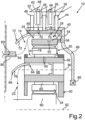
2 ausschnittsweise eine schematische Längsschnittansicht einer nicht unter den Anspruch 1 fallenden zweiten Ausführungsform des Planetengetriebes.
-
1 a detail of a schematic longitudinal sectional view of a first embodiment of a planetary gear, in particular for a motor vehicle; and -
2 a detail of a schematic longitudinal sectional view of a second embodiment of the planetary gear that does not fall under claim 1.
In den Figuren sind gleiche oder funktionsgleiche Elemente mit gleichen Bezugszeichen versehen.In the figures, identical or functionally identical elements are provided with the same reference numerals.
Das Planetengetriebe 10 weist eine erste Fangrinne 12 für ein Schmiermittel auf. Bei dem Schmiermittel, welches Bestandteil des Planetengetriebes 10 sein kann, handelt es sich vorzugsweise um ein flüssiges Schmiermittel, insbesondere um Öl. In
Das Planetengetriebe 10 weist einen Planetenradsatz 28 auf, welcher auch als Planetensatz bezeichnet wird. Der Planetenradsatz 28 weist zumindest einen Planetenträger 30 auf, welcher um eine Planetenradsatzdrehachse 92 relativ zu einem Gehäuse 32 des Planetengetriebes 10 drehbar ist. Es ist erkennbar, dass der Planetenträger 30 zumindest teilweise in dem Gehäuse 32 angeordnet ist. Der Planetenradsatz 28 weist drehbar an dem Planetenträger 30 gelagerte Planetenräder auf, von denen ein mit 34 bezeichnetes Planetenrad in
Das Planetengetriebe 10 weist außerdem eine auch als Reibkupplung bezeichnete oder als Reibkupplung ausgebildete Lamellenkupplung 39 auf. Die Lamellenkupplung 39 umfasst einen Innenlamellenträger 40 als ersten Lamellenträger, welcher, insbesondere permanent, drehfest mit der ersten Fangrinne 12 verbunden ist. Beispielsweise ist die erste Fangrinne 12 separat vom Innenlamellenträger 40 ausgebildet und, insbesondere permanent, drehfest mit dem Innenlamellenträger 40 verbunden. Die Lamellenkupplung 39 umfasst außerdem einen Außenlamellenträger 42 als zweiten Lamellenträger, welcher, insbesondere permanent, drehfest mit dem Gehäuse 32 des Planetengetriebes 10 verbunden ist. Des Weiteren umfasst die Lamellenkupplung 39 einen Satz 44 von Reiblamellen 46 und 48. Der Satz ist ein Lamellenpaket oder wird auch als Lamellenpaket bezeichnet, wobei das Lamellenpaket durch die Reiblamellen 46 und 48 gebildet ist. Aus
Um nun eine besonders vorteilhafte und bedarfsgerecht, auch als Schmiermittelversorgung bezeichnete Versorgung des Lamellenpakets mit dem Schmiermittel realisieren zu können, ist der Innenlamellenträger 40, insbesondere permanent, drehfest mit dem Hohlrad 38 verbunden. Hierdurch kann das Hohlrad 38 über den Innenlamellenträger und mittels des Lamellenpakets drehfest mit dem Gehäuse 32 verbunden werden, sodass das Hohlrad 38 mittels der Lamellenkupplung 44 drehfest mit dem Gehäuse 32 verbindbar ist. Die erste Fangrinne 12 ist, insbesondere permanent, drehfest mit dem Innenlamellenträger 40 verbunden. Beispielsweise ist die erste Fangrinne 12 separat von dem Innenlamellenträger 40 ausgebildet und, insbesondere permanent, drehfest mit dem Innenlamellenträger 40 verbunden.In order to be able to realize a particularly advantageous and needs-based supply of the disk pack with the lubricant, also known as lubricant supply, the
Aus
Das Planetengetriebe 10 weist, insbesondere das Planetenrad 34, einen Planetenradbolzen 58 auf, welcher, insbesondere permanent, drehfest mit dem Planetenträger 30 verbunden ist. Das Planetenrad 34 ist, vorliegend über ein Wälzlager 60, um die Planetenraddrehachse 36 relativ zu dem Planetenradbolzen 58 und relativ zu dem Planetenträger 30 drehbar an dem Planetenradbolzen 58, welcher auch einfach als Bolzen bezeichnet wird, gelagert. Der Planetenradbolzen 58 weist einen senkrecht zu der Planetenraddrehachse 36 und somit in radialer Richtung des Planetengetriebes 10 verlaufenden, zweiten Schmiermittelkanal 62 auf. Dies bedeutet, dass der zweite Schmiermittelkanal 62 in radialer Richtung des Planetengetriebes 10 und somit des Planetenrads 34 verläuft und entlang einer zweiten Strömungsrichtung von dem Schmiermittel, insbesondere von einer siebten der Strömungen des Schmiermittels, durchströmbar ist, wobei die siebte Strömung mit 64 bezeichnet ist. Dabei verläuft die zweite Strömungsrichtung senkrecht zur Planetenraddrehachse 36 und auch senkrecht zur Planetenradsatzdrehachse 92. Es ist erkennbar, dass der zweite Schmiermittelkanal 62 hinsichtlich der Planetenradsatzdrehachse 92 und auch hinsichtlich der Planetenraddrehachse 36 axial überlappend zu dem Wälzlager 60 angeordnet ist.The
Bei der ersten Ausführungsform weist das Planetengetriebe 10 eine zusätzlich zu der ersten Fangrinne vorgesehene zweite Fangrinne 66 auf, welche, insbesondere direkt, drehfest mit dem Planetenradbolzen 58 verbunden ist. Es ist erkennbar, dass die Fangrinne 66 radial innerhalb der ersten Fangrinne 12 angeordnet ist. Mit anderen Worten ist die erste Fangrinne 12 in radialer Richtung des Planetengetriebes 10 weiter außen angeordnet als die Fangrinne 66, wobei zumindest ein Teilbereich der Fangrinne 66 in radialer Richtung des Planetengetriebes 10 nach außen hin durch die erste Fangrinne 12 überlappt ist. Dabei weist der Planetenradbolzen 58 ein Sackloch 68 auf. Das Sackloch 68 ist eine auch als Loch bezeichnete Öffnung, die an ihrem ersten axialen Ende, welches der Fangrinne 66 zugewandt ist, offen ist. An ihrem zweiten axialen Ende ist die Öffnung (das Sackloch 68) verschlossen, wobei das zweite Ende in axialer Richtung des Planetenradbolzens 58 und des Planetengetriebes 10 insgesamt dem ersten Ende gegenüberliegt und von der Fangrinne 66 abgewandt ist. Mit dem Begriff „Sackloch“ 68 ist hier somit ein einseitig verschlossenes Loch gemeint. Das einseitig verschlossene Loch kann durch eine an sich bekannte Sacklochbohrung gebildet sein oder durch einen zunächst beidseitig offenen Zylinder, der dann nachträglich einseitig verschlossen wird. Es ist erkennbar, dass die zweite Fangrinne 66 axial angrenzend an das Sackloch 68, insbesondere an das erste Ende, angeordnet ist.In the first embodiment, the
Der Innenlamellenträger 40 weist radial verlaufende, dritte Schmiermittelkanäle 70 auf. Dies bedeutet, dass der jeweilige, dritte Schmiermittelkanal 70 in radialer Richtung des Planetengetriebes 10 verläuft, mithin entlang einer dritten Strömungsrichtung von dem Schmiermittel durchströmbar ist, wobei die dritte Strömungsrichtung in radialer Richtung des Planetengetriebes 10 und somit senkrecht zur Planetenradsatzdrehachse 92 verläuft.The
Die erste Fangrinne 12 weist eine in radialer Richtung des Planetengetriebes 10 nach innen weisende, konkave, erste Oberfläche 72 auf, welche als eine erste Fangfläche zum Auffangen des Schmiermittels ausgebildet ist. Insbesondere ist die Oberfläche 72 der zweiten Fangrinne 66 zugewandt. Die erste Fangrinne 12, insbesondere die Oberfläche 72, weist einen koaxial zu der Planetenradsatzdrehachse 92 angeordneten Kreisabschnitt 74 auf. Die zweite Fangrinne 66 weist eine in radialer Richtung des Planetengetriebes 10 nach innen weisende, zweite Oberfläche 76 auf, welche konkav ausgebildet ist und von der Oberfläche 72 weg weist.The
Es ist erkennbar, dass die zweite Fangrinne 66 wenigstens einen vierten Schmiermittelkanal 78 aufweist, welcher vorteilhaft radial, mithin in radialer Richtung des Planetengetriebes 10, das heißt vorteilhaft radial bezogen auf die Planetenradsatzdrehachse 92, verläuft. Dies bedeutet, dass der vierte Schmiermittelkanal 78, welcher als Durchgangsöffnung ausgebildet ist, entlang einer vierten Strömungsrichtung von dem Schmiermittel, insbesondere von einer Strömung 16, durchströmbar ist, wobei die vierte Strömungsrichtung in radialer Richtung des Planetengetriebes 10 verläuft. Es ist erkennbar, dass der vierte Schmiermittelkanal 78 die zweite Fangrinne 66 in radialer Richtung vollständig durchdringt. Durch den vierten Schmiermittelkanal 78 kann ein Teil des durch die zweite Fangrinne 66 aufgefangenen Schmiermittels an dem zweiten Schmiermittelkanal 62 vorbei und zu der ersten Fangrinne 12 geleitet werden.It can be seen that the
Vorgesehen ist auch ein parallel zu der Planetenradsatzdrehachse 92 angeordnetes oder verlaufendes Schmiermittelrohr 80. Dies bedeutet, dass das Schmiermittelrohr 80, insbesondere ein fünfter Schmiermittelkanal 82 des Schmiermittelrohrs 80, entlang einer fünften Strömungsrichtung von dem Schmiermittel, insbesondere von der Strömung 14, durchströmbar ist, wobei die fünfte Strömungsrichtung in axialer Richtung des Planetengetriebes 10, vorliegend parallel zur Planetenradsatzdrehachse 92 verläuft. Der Schmiermittelkanal 82 und somit das Schmiermittelrohr 80 weisen eine einfach auch als Austritt bezeichnete Austrittsöffnung 84 auf, welche von dem die Strömung 14 bildenden Schmiermittel durchströmbar ist. Über die Austrittsöffnung 84 kann das Schmiermittel aus dem Schmiermittelkanal 82 und somit aus dem Schmiermittelrohr 80 ausströmen. Insbesondere kann das Schmiermittelrohr 80 das Schmiermittel aus dem Schmiermittelkanal 82 über die Austrittsöffnung 84 ausspritzen und somit bereitstellen. Das Schmiermittelrohr 80, insbesondere die Austrittsöffnung 84, ist axial überlappend zu der Fangrinne 12 angeordnet, vorliegend derart, dass die Austrittsöffnung 84 in radialer Richtung des Planetengetriebes 10 nach außen hin durch die Fangrinne 12, insbesondere durch die Oberfläche 72, überlappt ist. Beispielsweise ist das Wälzlager 60 als ein Nadellager ausgebildet.A
Bei der ersten Ausführungsform weist das Planetengetriebe 10 ein Tellerelement 86 auf, welches, insbesondere permanent, drehfest mit dem Hohlrad 38 verbunden ist. Über das Tellerelement 86 sind das Hohlrad 38 und bei der ersten Ausführungsform auch der Innenlamellenträger 40 gegenüber oder an einer radial innerhalb des Hohlrads 39 angeordneten Lagerstelle abzustützen oder abgestützt, insbesondere um die Planetenradsatzdrehachse 92 relativ zu dem Gehäuse 32 drehbar gelagert.In the first embodiment, the
Bei der ersten Ausführungsform ist der Planetenradbolzen 58 hohl, insbesondere derart, dass der Planetenradbolzen 58 entlang seiner axialen Richtung vollständig von einer Durchgangsöffnung durchdrungen ist. Zu Bildung des Sacklochs 68 ist in der Durchgangsöffnung des Planetenradbolzens 58 ein auch als Stopfen bezeichnetes Verschlusselement 87 angeordnet, durch welches das Sackloch 68 an seinem zweiten Ende fluidisch versperrt oder geschlossen ist.In the first embodiment, the
Aus
Die zweite Ausführungsform unterscheidet sich insbesondere dadurch von der ersten Ausführungsform, dass die zweite Fangrinne 66 den Schmiermittelkanal 78 nicht aufweist. Bei der ersten Ausführungsform wird die Strömung 22 mittels des Schmiermittelkanals 78 in die Strömungen 16 und 64 als Teilströmungen aufgeteilt, was bei der zweiten Ausführungsform entfällt. Somit entfällt bei der zweiten Ausführungsform die Strömung 16. Bei der zweiten Ausführungsform resultiert die Strömung 64 durch das Sackloch 68 und somit durch den Planetenradbolzen 58 aus der Strömung 22, derart, dass die Strömung 64 der Strömung 22 entspricht. Wie bei der ersten Ausführungsform wird die Strömung 64, welche den Schmiermittelkanal 62 durchströmt, in die Strömungen 18 und 20 aufgeteilt. Bei der zweiten Ausführungsform strömt die Strömung 14 durch den Schmiermittelkanal 82 und somit durch die Austrittsöffnung 84 hindurch, wobei wie bei der ersten Ausführungsform die Strömungen 14 und 18 mittels der ersten Fangrinne 12 aufgefangen werden. Hierdurch werden die Strömungen 14 und 18 zu der Strömung 24 vereinigt. Das die Strömungen 20 und 24 bildende Schmiermittel strömt in radialer Richtung des Planetengetriebes 10 von innen nach außen durch die Schmiermittelkanäle 70 und hierdurch zu dem, insbesondere in das, Lamellenpaket. Dadurch kann eine besonders vorteilhafte bedarfsgerechte Schmiermittelversorgung des Lamellenpakets gewährleistet werden.The second embodiment differs from the first embodiment in particular in that the
Das zuvor genannte Sonnenrad ist in
BezugszeichenlisteReference symbol list
- 1010
- PlanetengetriebePlanetary gear
- 1212
- erste Fangrinnefirst gutter
- 1414
- Strömungflow
- 1616
- Strömungflow
- 1818
- Strömungflow
- 2020
- Strömungflow
- 2222
- Strömungflow
- 2424
- Strömungflow
- 2626
- Strömungflow
- 2828
- PlanetenradsatzPlanetary gear set
- 3030
- PlanetenträgerPlanet carrier
- 3232
- GehäuseHousing
- 3434
- PlanetenradPlanetary gear
- 3636
- PlanetenraddrehachsePlanetary wheel rotation axis
- 3838
- Hohlradring gear
- 3939
- LamellenkupplungMulti-plate clutch
- 4040
- InnenlamellenträgerInner disk carrier
- 4242
- AußenlamellenträgerExternal disk carrier
- 4444
- Satz von ReiblamellenSet of friction plates
- 4646
- ReiblamelleFriction plate
- 4848
- ReiblamelleFriction plate
- 5050
- erster Verzahnungsabschnittfirst gear section
- 5252
- zweiter Verzahnungsabschnittsecond gear section
- 5454
- ZylinderabschnittCylinder section
- 5656
- erster Schmiermittelkanalfirst lubricant channel
- 5858
- PlanetenradbolzenPlanetary gear bolt
- 6060
- Wälzlagerroller bearing
- 6262
- zweiter Schmiermittelkanalsecond lubricant channel
- 6464
- Strömungflow
- 6666
- zweite Fangrinnesecond gutter
- 6868
- Sacklochblind hole
- 7070
- dritter Schmiermittelkanalthird lubricant channel
- 7272
- erste Oberflächefirst surface
- 7474
- KreisabschnittCircle section
- 7676
- zweite Oberflächesecond surface
- 7878
- vierter Schmiermittelkanalfourth lubricant channel
- 8080
- SchmiermittelrohrLubricant tube
- 8282
- fünfter Schmiermittelkanalfifth lubricant channel
- 8484
- AustrittsöffnungExit opening
- 8686
- TellerelementPlate element
- 8787
- VerschlusselementClosure element
- 8888
- LagerstelleStorage location
- 9090
- Sonnenradsun gear
Claims (8)
Priority Applications (4)
| Application Number | Priority Date | Filing Date | Title |
|---|---|---|---|
| DE102022003153.1A DE102022003153B3 (en) | 2022-08-29 | 2022-08-29 | Planetary gear, especially for a motor vehicle |
| CN202380054006.4A CN119585542A (en) | 2022-08-29 | 2023-07-21 | Planetary gear transmission, especially for motor vehicles |
| PCT/EP2023/070379 WO2024046654A1 (en) | 2022-08-29 | 2023-07-21 | Planetary transmission, in particular for a motor vehicle |
| US19/107,156 US12601400B2 (en) | 2022-08-29 | 2023-07-21 | Planetary transmission, in particular for a motor vehicle |
Applications Claiming Priority (1)
| Application Number | Priority Date | Filing Date | Title |
|---|---|---|---|
| DE102022003153.1A DE102022003153B3 (en) | 2022-08-29 | 2022-08-29 | Planetary gear, especially for a motor vehicle |
Publications (1)
| Publication Number | Publication Date |
|---|---|
| DE102022003153B3 true DE102022003153B3 (en) | 2023-11-16 |
Family
ID=87468448
Family Applications (1)
| Application Number | Title | Priority Date | Filing Date |
|---|---|---|---|
| DE102022003153.1A Active DE102022003153B3 (en) | 2022-08-29 | 2022-08-29 | Planetary gear, especially for a motor vehicle |
Country Status (4)
| Country | Link |
|---|---|
| US (1) | US12601400B2 (en) |
| CN (1) | CN119585542A (en) |
| DE (1) | DE102022003153B3 (en) |
| WO (1) | WO2024046654A1 (en) |
Cited By (1)
| Publication number | Priority date | Publication date | Assignee | Title |
|---|---|---|---|---|
| WO2026067922A1 (en) * | 2024-09-26 | 2026-04-02 | Schaeffler Technologies AG & Co. KG | Multi-plate brake or multi-plate clutch with external lubrication |
Citations (6)
| Publication number | Priority date | Publication date | Assignee | Title |
|---|---|---|---|---|
| DE7322916U (en) | 1973-06-20 | 1975-11-13 | Voith Getriebe Kg | FLAT DISC CLUTCH OR BRAKE FOR MANUAL TRANSMISSION |
| JPS5142861A (en) | 1974-10-09 | 1976-04-12 | Aisin Seiki | JUSEIHAGURUMASOCHINO JUNKATSUSOCHI |
| JPH0893889A (en) | 1994-09-19 | 1996-04-12 | Mazda Motor Corp | One-way clutch and automatic transmission with one-way clutch |
| JP2010065741A (en) | 2008-09-09 | 2010-03-25 | Honda Motor Co Ltd | Lubricating structure for vehicular automatic transmission |
| KR20120037781A (en) | 2010-10-12 | 2012-04-20 | 현대 파워텍 주식회사 | Friction device for auto transmission |
| DE102011086376A1 (en) | 2011-11-15 | 2013-05-16 | Zf Friedrichshafen Ag | Oil supply device for multi-disk brake of gear module in vehicle, has valve, which controls accurate oil gating for cooling multi-disk brake in drive conditions with slipping multi-disk brake, where oil is injected into inner disk carrier |
Family Cites Families (8)
| Publication number | Priority date | Publication date | Assignee | Title |
|---|---|---|---|---|
| DE19534791C2 (en) * | 1995-09-20 | 1997-11-13 | Ford Werke Ag | Planet carrier arrangement with axial support |
| DE102008000900A1 (en) * | 2008-04-01 | 2009-10-08 | Zf Friedrichshafen Ag | planetary gear |
| US8353797B2 (en) * | 2010-07-29 | 2013-01-15 | GM Global Technology Operations LLC | Lubrication system for a planetary gear set |
| US9429227B2 (en) * | 2014-02-19 | 2016-08-30 | Fairfield Manufacturing Company, Inc. | Planetary gearbox with integral service brake |
| EP3091255B1 (en) * | 2015-05-07 | 2019-11-06 | Flender GmbH | Planetary gear unit |
| KR101755195B1 (en) * | 2015-10-06 | 2017-07-20 | 현대 파워텍 주식회사 | Lubrication apparatus of automatic transmission |
| FR3084428B1 (en) * | 2018-07-26 | 2020-09-11 | Safran Trans Systems | PLANETARY OR EPICYCLOIDAL GEAR REDUCER CAGE FOR TURBOMACHINE |
| US20250137529A1 (en) * | 2022-06-22 | 2025-05-01 | General Electric Company | Gearbox assembly with lubricant extraction volume ratio |
-
2022
- 2022-08-29 DE DE102022003153.1A patent/DE102022003153B3/en active Active
-
2023
- 2023-07-21 CN CN202380054006.4A patent/CN119585542A/en active Pending
- 2023-07-21 US US19/107,156 patent/US12601400B2/en active Active
- 2023-07-21 WO PCT/EP2023/070379 patent/WO2024046654A1/en not_active Ceased
Patent Citations (6)
| Publication number | Priority date | Publication date | Assignee | Title |
|---|---|---|---|---|
| DE7322916U (en) | 1973-06-20 | 1975-11-13 | Voith Getriebe Kg | FLAT DISC CLUTCH OR BRAKE FOR MANUAL TRANSMISSION |
| JPS5142861A (en) | 1974-10-09 | 1976-04-12 | Aisin Seiki | JUSEIHAGURUMASOCHINO JUNKATSUSOCHI |
| JPH0893889A (en) | 1994-09-19 | 1996-04-12 | Mazda Motor Corp | One-way clutch and automatic transmission with one-way clutch |
| JP2010065741A (en) | 2008-09-09 | 2010-03-25 | Honda Motor Co Ltd | Lubricating structure for vehicular automatic transmission |
| KR20120037781A (en) | 2010-10-12 | 2012-04-20 | 현대 파워텍 주식회사 | Friction device for auto transmission |
| DE102011086376A1 (en) | 2011-11-15 | 2013-05-16 | Zf Friedrichshafen Ag | Oil supply device for multi-disk brake of gear module in vehicle, has valve, which controls accurate oil gating for cooling multi-disk brake in drive conditions with slipping multi-disk brake, where oil is injected into inner disk carrier |
Cited By (1)
| Publication number | Priority date | Publication date | Assignee | Title |
|---|---|---|---|---|
| WO2026067922A1 (en) * | 2024-09-26 | 2026-04-02 | Schaeffler Technologies AG & Co. KG | Multi-plate brake or multi-plate clutch with external lubrication |
Also Published As
| Publication number | Publication date |
|---|---|
| WO2024046654A1 (en) | 2024-03-07 |
| US12601400B2 (en) | 2026-04-14 |
| US20260078817A1 (en) | 2026-03-19 |
| CN119585542A (en) | 2025-03-07 |
Similar Documents
| Publication | Publication Date | Title |
|---|---|---|
| DE102021006602A1 (en) | Axial flow machine for a motor vehicle | |
| DE102021006008A1 (en) | Axial flow machine for a motor vehicle | |
| DE102019205760A1 (en) | Lubricator and planetary gear and motor vehicle | |
| AT522062B1 (en) | Axle center gear | |
| DE102022003153B3 (en) | Planetary gear, especially for a motor vehicle | |
| DE102022213923B4 (en) | Transmission for a vehicle and drive train with such a transmission | |
| DE102017102348B4 (en) | Double clutch transmission with bridge clutch | |
| DE102019008948A1 (en) | Gearboxes for a motor vehicle, in particular for a motor vehicle | |
| DE102023004979B3 (en) | Wheel hub drive for a motor vehicle | |
| DE102021005016A1 (en) | Electric drive device for a motor vehicle, in particular for a motor vehicle, and motor vehicle | |
| EP1934068B1 (en) | Engine-driven vehicle having a gear mechanism for an auxiliary unit, in particular as a planetary gear set for integration into the drive of the auxiliary unit, and corresponding gear mechanism | |
| DE102021004615B4 (en) | Drive device for a motor vehicle, in particular for a motor vehicle | |
| DE102023004713A1 (en) | Electric drive system for a motor vehicle and motor vehicle | |
| DE102022004132A1 (en) | Electric drive device for an electrified motor vehicle | |
| DE102020214517B4 (en) | Gear for setting up an axle offset, wheelset arrangement and hybrid transmission for a motor vehicle powertrain | |
| DE102022214115A1 (en) | Motor vehicle transmission for an at least partially electrically powered motor vehicle | |
| DE102022213926A1 (en) | Transmission for a vehicle and drive train with such a transmission | |
| DE102021132892A1 (en) | planetary gear arrangement | |
| WO2018197127A1 (en) | Transmission for a motor vehicle | |
| DE102022004848B3 (en) | Electric drive device for a motor vehicle, in particular for a motor vehicle, and motor vehicle | |
| DE102023000286B4 (en) | Electric drive system for a motor vehicle, in particular for a motor vehicle, and motor vehicle | |
| DE102024001259B4 (en) | electric vehicle | |
| DE102021005017A1 (en) | Electric drive device for a motor vehicle, in particular for a motor vehicle, and motor vehicle | |
| DE102024002413B3 (en) | Wheel hub drive for a motor vehicle | |
| DE102023005243B3 (en) | Planetary gear for a motor vehicle and motor vehicle |
Legal Events
| Date | Code | Title | Description |
|---|---|---|---|
| R012 | Request for examination validly filed | ||
| R016 | Response to examination communication | ||
| R018 | Grant decision by examination section/examining division | ||
| R020 | Patent grant now final |