DE102021211185A1 - Device and method for controlling a robot - Google Patents
Device and method for controlling a robot Download PDFInfo
- Publication number
- DE102021211185A1 DE102021211185A1 DE102021211185.8A DE102021211185A DE102021211185A1 DE 102021211185 A1 DE102021211185 A1 DE 102021211185A1 DE 102021211185 A DE102021211185 A DE 102021211185A DE 102021211185 A1 DE102021211185 A1 DE 102021211185A1
- Authority
- DE
- Germany
- Prior art keywords
- feature points
- robot
- pose
- coordinates
- descriptor
- Prior art date
- Legal status (The legal status is an assumption and is not a legal conclusion. Google has not performed a legal analysis and makes no representation as to the accuracy of the status listed.)
- Granted
Links
Images

Classifications
-
- B—PERFORMING OPERATIONS; TRANSPORTING
- B25—HAND TOOLS; PORTABLE POWER-DRIVEN TOOLS; MANIPULATORS
- B25J—MANIPULATORS; CHAMBERS PROVIDED WITH MANIPULATION DEVICES
- B25J9/00—Program-controlled manipulators
- B25J9/16—Program controls
- B25J9/1694—Program controls characterised by use of sensors other than normal servo-feedback from position, speed or acceleration sensors, perception control, multi-sensor controlled systems, sensor fusion
- B25J9/1697—Vision controlled systems
-
- B—PERFORMING OPERATIONS; TRANSPORTING
- B25—HAND TOOLS; PORTABLE POWER-DRIVEN TOOLS; MANIPULATORS
- B25J—MANIPULATORS; CHAMBERS PROVIDED WITH MANIPULATION DEVICES
- B25J19/00—Accessories fitted to manipulators, e.g. for monitoring, for viewing; Safety devices combined with or specially adapted for use in connection with manipulators
- B25J19/02—Sensing devices
- B25J19/021—Optical sensing devices
- B25J19/023—Optical sensing devices including video camera means
-
- B—PERFORMING OPERATIONS; TRANSPORTING
- B25—HAND TOOLS; PORTABLE POWER-DRIVEN TOOLS; MANIPULATORS
- B25J—MANIPULATORS; CHAMBERS PROVIDED WITH MANIPULATION DEVICES
- B25J9/00—Program-controlled manipulators
- B25J9/16—Program controls
- B25J9/1602—Program controls characterised by the control system, structure, architecture
- B25J9/161—Hardware, e.g. neural networks, fuzzy logic, interfaces, processor
-
- B—PERFORMING OPERATIONS; TRANSPORTING
- B25—HAND TOOLS; PORTABLE POWER-DRIVEN TOOLS; MANIPULATORS
- B25J—MANIPULATORS; CHAMBERS PROVIDED WITH MANIPULATION DEVICES
- B25J9/00—Program-controlled manipulators
- B25J9/16—Program controls
- B25J9/1628—Program controls characterised by the control loop
- B25J9/163—Program controls characterised by the control loop learning, adaptive, model based, rule based expert control
-
- G—PHYSICS
- G05—CONTROLLING; REGULATING
- G05B—CONTROL OR REGULATING SYSTEMS IN GENERAL; FUNCTIONAL ELEMENTS OF SUCH SYSTEMS; MONITORING OR TESTING ARRANGEMENTS FOR SUCH SYSTEMS OR ELEMENTS
- G05B2219/00—Program-control systems
- G05B2219/30—Nc systems
- G05B2219/39—Robotics, robotics to robotics hand
- G05B2219/39546—Map human grasps to manipulator grasps
-
- G—PHYSICS
- G05—CONTROLLING; REGULATING
- G05B—CONTROL OR REGULATING SYSTEMS IN GENERAL; FUNCTIONAL ELEMENTS OF SUCH SYSTEMS; MONITORING OR TESTING ARRANGEMENTS FOR SUCH SYSTEMS OR ELEMENTS
- G05B2219/00—Program-control systems
- G05B2219/30—Nc systems
- G05B2219/40—Robotics, robotics mapping to robotics vision
- G05B2219/40116—Learn by operator observation, symbiosis, show, watch
Landscapes
- Engineering & Computer Science (AREA)
- Robotics (AREA)
- Mechanical Engineering (AREA)
- Automation & Control Theory (AREA)
- Multimedia (AREA)
- Artificial Intelligence (AREA)
- Physics & Mathematics (AREA)
- Evolutionary Computation (AREA)
- Fuzzy Systems (AREA)
- Mathematical Physics (AREA)
- Software Systems (AREA)
- Image Analysis (AREA)
- Manipulator (AREA)
Abstract
Gemäß verschiedenen Ausführungsformen wird ein Verfahren zum Steuern eines Roboters beschrieben, das die folgenden Schritte umfasst: Durchführen von Demonstrationen und Deskriptorbildern für die Demonstrationen aus der Sicht des Roboters auf das Objekt, Auswählen einer Menge von Merkmalspunkten, wobei die Merkmalspunkte durch Suchen eines Optimums einer Zielfunktion ausgewählt werden, die ausgewählte Merkmalspunkte belohnt, die in den Deskriptorbildern sichtbar sind, Trainieren eines Robotersteuerungsmodells unter Verwendung der Demonstrationen und Steuern des Roboters für eine Steuerszene mit dem Objekt durch Bestimmen eines Deskriptorbildes des Objekts, Lokalisieren des ausgewählten Satzes von Merkmalspunkten in dem Deskriptorbild des Objekts, Bestimmen von Koordinaten der lokalisierten Merkmalspunkte, Schätzen einer Pose aus den bestimmten Koordinaten und Steuern des Roboters zum Handhaben des Objekts mittels des Robotersteuerungsmodells mit der geschätzten Pose.

Description
Stand der TechnikState of the art
Die vorliegende Offenbarung bezieht sich auf Vorrichtungen und Verfahren zum Steuern eines Roboters.The present disclosure relates to devices and methods for controlling a robot.
Roboterfähigkeiten können mithilfe von Lernen-durch-Domonstration- (Learning from Demonstration, LfD) Ansätzen programmiert werden, bei denen ein Roboter einen vorgegebenen Plan einer Fähigkeit anhand von Demonstrationen erlernt. Der Grundgedanke von LfD ist die Parametrisierung von Gauß-Funktionen durch die Pose einer Kamera, die den Arbeitsraum des Roboters überwacht, und ein Zielobjekt, das durch den Roboter gehandhabt werden soll. Hierfür und auch für die Verwendung des resultierenden Robotersteuerungsmodells muss eine Schätzung der Pose des Objekts in einer gegebenen Szene durchgeführt werden. Eine Möglichkeit sind auf RGB-Bildern basierende Verfahren zur Posenschätzung. Diese könnten jedoch unzuverlässig sein.Robot skills can be programmed using learning from demonstration (LfD) approaches, in which a robot learns a predetermined blueprint of a skill through demonstrations. The basic idea of LfD is the parameterization of Gaussian functions by posing a camera monitoring the robot's workspace and a target to be manipulated by the robot. For this, and also for using the resulting robot control model, an estimation of the pose of the object in a given scene has to be performed. One possibility are pose estimation methods based on RGB images. However, these may be unreliable.
Daher sind Ansätze wünschenswert, die eine zuverlässige Posenschätzung in einem LfD-Kontext ermöglichen.Therefore, approaches that enable reliable pose estimation in an LfD context are desirable.
Offenbarung der ErfindungDisclosure of Invention
Gemäß verschiedenen Ausführungsformen wird ein Verfahren zum Steuern eines Roboters bereitgestellt, umfassend das Durchführen von Demonstrationen, wobei jede Demonstration eine Handhabung eines Objekts vorführt, für jede Demonstration das Bereitstellen mindestens eines Deskriptorbildes aus Sicht des Roboters des Objekts, wobei das Deskriptorbild Merkmalspunkte für Orte auf dem Objekt spezifiziert, Auswählen eines Satzes von Merkmalspunkten aus den spezifizierten Merkmalspunkten, wobei die Merkmalspunkte durch Suchen eines Optimums einer Zielfunktion ausgewählt werden, die ausgewählte Merkmalspunkte belohnt, die in den Deskriptorbildern sichtbar sind, Trainieren eines Robotersteuerungsmodell anhand der Demonstrationen, wobei das Robotersteuerungsmodell dazu ausgelegt ist, Steuerinformationen in Abhängigkeit von einer eingegebenen Objektpose auszugeben, und Steuern des Roboters für eine Steuerszene mit dem Objekt durch Bestimmen eines Deskriptorbildes des Objekts aus der Sicht des Roboters, Lokalisieren des ausgewählten Satzes von Merkmalspunkten in dem Deskriptorbild des Objekts, Bestimmen von Koordinaten der lokalisierten Merkmalspunkte für die Steuerszene, Schätzen einer Pose aus den bestimmten Koordinaten und Steuern des Roboters zur Handhabung des Objekts mittels des Robotersteuerungsmodells, wobei die geschätzte Pose dem Robotersteuerungsmodell als Eingabe zugeführt wird.According to various embodiments, a method for controlling a robot is provided, comprising performing demonstrations, each demonstration showing how to handle an object, for each demonstration providing at least one descriptor image from the robot's point of view of the object, the descriptor image containing feature points for locations on the Object specified, selecting a set of feature points from the specified feature points, the feature points being selected by finding an optimum of an objective function that rewards selected feature points visible in the descriptor images, training a robot control model based on the demonstrations, the robot control model being designed to do so to output control information dependent on an inputted object pose, and controlling the robot for a control scene with the object by determining a descriptor image of the object as seen by the robot, locating the selected set of feature points in the object's descriptor image, determining coordinates of the located feature points for the control scene, estimating a pose from the determined coordinates and controlling the robot to manipulate the object using the robot control model, the estimated pose being provided as input to the robot control model.
Eine automatische Auswahl von Merkmalspunkten, die für die Posenschätzung eines Objekts verwendet werden, wird damit so vorgenommen, dass die ausgewählten Merkmalspunkte gut sichtbar sind (z. B. in den meisten Deskriptorbildern). Die Auswahl der Merkmalspunkte basiert also auf der Annahme, dass die Merkmale, die in den Demonstrationen (z. B. in den Bildern, die für die Aufnahme der Demonstrationen aufgenommen wurden) zu sehen sind, in dem Sinne gut sind, dass sie meistens in Szenen zu sehen sind, in denen der Roboter die entsprechende Manipulationsfähigkeit ausführen soll.An automatic selection of feature points used for the pose estimation of an object is thus made in such a way that the selected feature points are clearly visible (e.g. in most descriptor images). The selection of feature points is thus based on the assumption that the features seen in the demonstrations (e.g. in the images taken to capture the demonstrations) are good in the sense that they are mostly in Scenes can be seen in which the robot should perform the corresponding manipulation ability.
Der Sichtwinkel des Roboters ist zum Beispiel der Sichtwinkel einer am Roboter angebrachten Kamera, z. B. der Sichtwinkel eines Endeffektors des Roboters.The robot's viewing angle is, for example, the viewing angle of a camera attached to the robot, e.g. B. the viewing angle of an end effector of the robot.
Somit ermöglicht das oben beschriebene Verfahren eine genaue und zuverlässige Schätzung der Pose (z. B. 6D-Pose) eines Objekts.Thus, the method described above enables an accurate and reliable estimation of the pose (e.g. 6D pose) of an object.
Im Folgenden werden verschiedene Beispiele angeführt.Various examples are given below.
Beispiel 1 ist ein Verfahren zum Steuern eines Roboters wie oben beschrieben.Example 1 is a method for controlling a robot as described above.
Beispiel 2 ist das Verfahren von Beispiel 1, wobei die Zielfunktion ferner eines oder mehr belohnt von: ausgewählten Merkmalspunkten, die im Deskriptorraum beabstandet sind, Orten auf dem Objekt, die den ausgewählten Merkmalspunkten entsprechen, die im Raum beabstandet sind, und einem niedrigen Erkennungsfehler für ausgewählte Merkmalspunkte für das Objekt.Example 2 is the method of Example 1, wherein the objective function further rewards one or more of: selected feature points spaced apart in descriptor space, locations on the object corresponding to the selected feature points spaced apart in space, and a low recognition error for selected feature points for the object.
Diese Bedingungen gewährleisten, dass die Merkmalspunkte für das Objekt zuverlässig erkannt werden können und dass nach ihrer Erkennung eine Pose des Objekts zuverlässig bestimmt werden kann.These conditions ensure that the feature points for the object can be reliably detected and that after their detection a pose of the object can be reliably determined.
Beispiel 3 ist das Verfahren von Beispiel 1 oder 2, das ferner das Anpassen einer Ebene an das Objekt und das Auswählen der Merkmalspunkte, sodass sie einen Koordinatenrahmen auf der Ebene definieren, und das Schätzen der Pose aus den bestimmten Koordinaten der lokalisierten Merkmalspunkte und Informationen über die Pose der angepassten Ebene umfasst.Example 3 is the method of Example 1 or 2, which further includes fitting a plane to the object and selecting the feature points so that they define a coordinate frame on the plane, and estimating the pose from the determined coordinates of the located feature points and information about includes the pose of the adjusted layer.
Dies gewährleistet eine zuverlässige Posenschätzung, selbst wenn das Objekt flach ist und/oder wenig Variation in einer räumlichen Richtung aufweist (d. h. kein „echtes“ 3D-Objekt ist).This ensures reliable pose estimation even when the object is flat and/or has little variation in one spatial direction (i.e. is not a "real" 3D object).
Beispiel 4 ist das Verfahren von Beispiel 3, wobei das Schätzen der Pose aus den bestimmten Koordinaten das Projizieren der Koordinaten der lokalisierten Merkmalspunkte auf die angepasste Hyperebene umfasst.Example 4 is the method of Example 3, wherein estimating the pose from the determined coordinates includes projecting the coordinates of the located feature points onto the fitted hyperplane.
So kann ein planarer Koordinatenrahmen (in der Ebene) abgeleitet werden, auch wenn erkannt wird, dass die Koordinaten der Merkmalspunkte nicht in der Ebene liegen.Thus, a planar (in-plane) coordinate frame can be derived even if it is recognized that the coordinates of the feature points are not in-plane.
Beispiel 5 ist das Verfahren von Beispiel 3 oder 4, wobei die Ebene an das Objekt angepasst wird, die Merkmalspunkte so ausgewählt werden, dass sie einen Koordinatenrahmen auf der Ebene definieren, und die Pose aus den ermittelten Koordinaten der lokalisierten Merkmalspunkte und Informationen über die Pose der Ebene geschätzt wird, falls eine Veränderung des Objekts in einer räumlichen Richtung unterhalb eines vorbestimmten Schwellenwerts liegt.Example 5 is the method of Example 3 or 4, fitting the plane to the object, selecting the feature points to define a coordinate frame on the plane, and posing from the determined coordinates of the located feature points and information about the pose of the plane is estimated if a change in the object in a spatial direction is below a predetermined threshold.
Auf diese Weise kann ein zuverlässiges Verfahren zur Posenbestimmung sowohl für echte als auch für nicht-echte 3D-Objekte trainiert werden. Insbesondere die Posenerkennung für echte 3D-Objekte ist immer noch effizient, da die (Hyper-) Ebenenanpassung nur bei Bedarf angewendet wird.In this way, a reliable pose determination method can be trained for both real and non-real 3D objects. In particular, pose detection for real 3D objects is still efficient, since (hyper)level adjustment is only applied when needed.
Beispiel 6 ist das Verfahren von einem der Beispiele 1 bis 5, das das Bestimmen einer Ableitungsregel eines Koordinatenrahmens aus den Koordinaten der ausgewählten Merkmalspunkte umfasst, wobei das Schätzen der Pose aus den bestimmten Koordinaten die Anwendung der Ableitungsregel auf die ausgewählten Merkmalspunkte umfasst, wobei die Ableitungsregel durch Suchen eines Minimums der Abhängigkeit des Koordinatenrahmens vom Rauschen in den Koordinaten bestimmt wird.Example 6 is the method of any one of Examples 1 to 5, comprising determining a derivation rule of a coordinate frame from the coordinates of the selected feature points, estimating the pose from the determined coordinates comprising applying the derivation rule to the selected feature points, the derivation rule is determined by finding a minimum of the dependence of the coordinate frame on noise in the coordinates.
Dies gewährleistet eine zuverlässige Posenerkennung auch bei Erkennungsfehlern der Merkmalspunkte.This ensures reliable pose detection even in the case of feature point detection errors.
Beispiel 7 ist das Verfahren von einem der Beispiele 1 bis 6, wobei das Trainieren des Robotersteuerungsmodells unter Verwendung der Demonstrationen für jede Demonstration das Lokalisieren des ausgewählten Satzes von Merkmalspunkten im Deskriptorbild des Objekts in der Demonstration, das Bestimmen von Koordinaten der lokalisierten Merkmalspunkte für die Demonstration und das Schätzen einer Pose aus den bestimmten Koordinaten für die Demonstration umfasst.Example 7 is the method of any of Examples 1 to 6, wherein training the robot control model using the demonstrations for each demonstration locating the selected set of feature points in the descriptor image of the object in the demonstration, determining coordinates of the located feature points for the demonstration and estimating a pose from the determined coordinates for the demonstration.
Das bedeutet, dass die ausgewählten Merkmalspunkte zur Posenschätzung für das Training des Robotersteuerungsmodells selbst verwendet werden können.This means that the selected pose estimation feature points can be used for training the robot control model itself.
Beispiel 8 ist das Verfahren von einem der Beispiele 1 bis 7, umfassend das Bestimmen des Deskriptorbildes des Objekts aus einem Kamerabild des Objekts durch ein dichtes Objektnetz.Example 8 is the method of any one of Examples 1 to 7, comprising determining the descriptor image of the object from a camera image of the object through a dense object mesh.
Ein dichtes Objektnetz (Dense Object Net, DON) kann trainiert werden, um Punkte auf einem Objekt eindeutig zu identifizieren. Solche Punkte können bei unterschiedlichen Konfigurationen des Objekts zuverlässig verfolgt werden. A Dense Object Net (DON) can be trained to uniquely identify points on an object. Such points can be tracked reliably for different configurations of the object.
Beispiel 9 ist eine Robotersteuervorrichtung, die dazu ausgelegt ist, ein Verfahren gemäß einem der Beispiele 1 bis 8 durchzuführen.Example 9 is a robot control device configured to perform a method according to any one of Examples 1 to 8.
Beispiel 10 ist ein Computerprogramm, das Anweisungen umfasst, die beim Ausführen durch einen Computer den Computer veranlassen, ein Verfahren gemäß einem der Beispiele 1 bis 8 durchzuführen.Example 10 is a computer program that includes instructions that, when executed by a computer, cause the computer to perform a method according to any one of Examples 1-8.
Beispiel 11 ist ein computerlesbaren Medium das Anweisungen umfasst, die beim Ausführen durch einen Computer den Computer veranlassen, ein Verfahren gemäß einem der Beispiele 1 bis 8 durchzuführen.Example 11 is a computer-readable medium that includes instructions that, when executed by a computer, cause the computer to perform a method according to any one of Examples 1-8.
In den Zeichnungen beziehen sich ähnliche Bezugszeichen allgemein auf dieselben Teile in den verschiedenen Ansichten. Die Zeichnungen sind nicht notwendigerweise maßstabsgetreu; der Schwerpunkt liegt stattdessen allgemein auf der Veranschaulichung der Prinzipien der Erfindung. In der folgenden Beschreibung werden verschiedene Aspekte der Offenbarung unter Bezugnahme auf die folgenden Zeichnungen beschrieben. Dabei gilt:
-
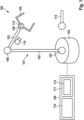
1 zeigt einen Roboter. -
2 veranschaulicht ein Verfahren zur Auswahl von Merkmalspunkten und zum Erlernen eines Koordinatenrahmens für ein Objekt in der Trainingsdatenmenge, das in einer Richtung wenig Variation aufweist, sowie die Anwendung des Koordinatenrahmens beim Einsatz. -
3 zeigt ein Flussdiagramm, das ein Verfahren zum Steuern eines Roboters veranschaulicht.
-
1 shows a robot. -
2 FIG. 12 illustrates a method for selecting feature points and learning a coordinate frame for an object in the training data set that has little variation in one direction, and applying the coordinate frame in the field. -
3 FIG. 12 shows a flow chart illustrating a method for controlling a robot.
Die folgende detaillierte Beschreibung bezieht sich auf die beigefügten Zeichnungen, die zur Veranschaulichung bestimmte Details und Aspekte dieser Offenbarung zeigen, in denen die Erfindung umgesetzt werden kann. Es können auch andere Aspekte genutzt und strukturelle, logische und elektrische Änderungen vorgenommen werden, ohne den Schutzumfang der Erfindung zu verlassen. Die verschiedenen Aspekte dieser Offenbarung schließen sich nicht unbedingt gegenseitig aus, da einige Aspekte dieser Offenbarung mit einem oder mehreren anderen Aspekten dieser Offenbarung kombiniert werden können, um neue Aspekte zu bilden.The following detailed description refers to the accompanying drawings that show by way of illustration certain details and aspects of this disclosure in which the invention may be practiced. Other aspects may be utilized and structural, logical, and electrical changes may be made without departing from the scope of the invention. The various aspects of this disclosure are not necessarily mutually exclusive, as some aspects of this disclosure can be combined with one or more other aspects of this disclosure to form new aspects.
Im Folgenden werden verschiedene Beispiele näher beschrieben.Various examples are described in more detail below.
Der Roboter 100 weist einen Roboterarm 101, zum Beispiel einen Industrieroboterarm zum Handhaben oder Montieren eines Werkstücks (oder eines oder mehrerer anderer Objekte), auf. Der Roboterarm 101 weist Manipulatoren 102, 103, 104 und eine Basis (oder Stütze) 105 auf, an der die Manipulatoren 102, 103, 104 befestigt sind. Der Begriff „Manipulator“ bezieht sich auf die bewegbaren Elemente des Roboterarms 101, deren Betätigung eine physische Interaktion mit der Umgebung ermöglicht, z. B. um eine Aufgabe auszuführen. Zur Steuerung weist der Roboter 100 eine (Roboter-) Steuervorrichtung 106 auf, die dazu ausgelegt ist, die Interaktion mit der Umgebung gemäß einem Steuerprogramm durchzuführen. Das letzte Element 104 (das am weitesten von der Halterung 105 entfernt ist) der Manipulatoren 102, 103, 104 wird auch als Endeffektor 104 bezeichnet und könnte ein oder mehrere Werkzeuge, wie z. B. ein Schweißbrenner, ein Greifinstrument, eine Lackierausrüstung oder dergleichen, sein.The
Die anderen Manipulatoren 102, 103 (näher an der Halterung 105) könnten eine Positioniervorrichtung bilden, sodass zusammen mit dem Endeffektor 104 der Roboterarm 101 mit dem Endeffektor 104 an seinem Ende bereitsteht. Der Roboterarm 101 ist ein mechanischer Arm, der ähnliche Funktionen wie ein menschlicher Arm (möglicherweise mit einem Werkzeug an seinem Ende) erfüllen kann.The
Der Roboterarm 101 könnte Gelenkelemente 107, 108, 109 enthalten, die die Manipulatoren 102, 103, 104 miteinander und mit der Halterung 105 verbinden. Ein Gelenkelement 107, 108, 109 könnte ein oder mehrere Gelenke aufweisen, von denen jedes den zugehörigen Manipulatoren eine Drehbewegung (d. h. eine Rotationsbewegung) und/oder eine Translationsbewegung (d. h. eine Verschiebung) relativ zueinander ermöglichen kann. Die Bewegung der Manipulatoren 102, 103, 104 könnte mithilfe von Aktuatoren eingeleitet werden, die durch die Steuervorrichtung 106 gesteuert werden.The
Der Begriff „Aktuator“ kann als Komponente verstanden werden, die dazu angepasst ist, als Reaktion auf einen Antrieb einen Mechanismus oder einen Prozess zu beeinflussen. Der Aktuator kann die durch die Steuervorrichtung 106 erteilten Anweisungen (die sogenannte Ansteuerung) in mechanische Bewegungen umsetzen. Der Aktuator, z. B. ein elektromechanischer Wandler, könnte dazu ausgelegt sein, bei Ansteuerung elektrische Energie in mechanische Energie umzuwandeln.The term "actuator" can be understood as a component that is adapted to affect a mechanism or process in response to a drive. The actuator can convert the instructions issued by the control device 106 (the so-called actuation) into mechanical movements. The actuator, e.g. B. an electromechanical converter could be designed to convert electrical energy into mechanical energy when activated.
Der Begriff „Steuervorrichtung“ kann als jede Art von Logik implementierender Einrichtung verstanden werden, die beispielsweise eine Schaltung und/oder einen Prozessor aufweisen kann, der in der Lage ist, in einem Speichermedium gespeicherte Software, Firmware oder eine Kombination davon auszuführen, und der Anweisungen, z. B. an einen Aktuator wie im vorliegenden Beispiel, erteilen kann. Die Steuervorrichtung könnte um Beispiel durch Programmcode (z. B. Software) dazu konfiguriert sein, den Betrieb eines Systems, im vorliegenden Beispiel eines Roboters, zu steuern.The term "controller" may be understood as any type of logic implementing device, which may include, for example, circuitry and/or a processor capable of executing software, firmware, or a combination thereof stored in a storage medium and the instructions , e.g. B. to an actuator as in the present example. The controller could be configured, for example, by program code (e.g., software) to control the operation of a system, in this example a robot.
Im vorliegenden Beispiel weist die Steuervorrichtung 106 einen oder mehrere Prozessoren 110 und einen Speicher 111 auf, der Code und Daten speichert, basierend auf dem der Prozessor 110 den Roboterarm 101 steuert. Gemäß verschiedenen Ausführungsformen steuert die Steuervorrichtung 106 den Roboterarm 101 basierend auf einem im Speicher 111 gespeicherten statistischen Modell 112.In the present example, the
Ein Roboter 100 kann die Vorteile von Lernen-durch-Domonstration- (Learning from Demonstration, LfD) Ansätzen nutzen, um zu lernen, eine Aufgabe auszuführen oder mit einem menschlichen Partner zusammenzuarbeiten. Menschliche Demonstrationen können durch ein probabilistisches Modell (auch als statistisches Modell bezeichnet) kodiert werden, das den vorgegebenen Plan der Aufgabe für den Roboter darstellt. Die Steuervorrichtung 106 kann anschließend das statistische Modell, das auch als Robotertrajektorienmodell bezeichnet wird, dazu verwenden, die gewünschten Roboterbewegungen zu erzeugen, möglicherweise in Abhängigkeit vom Zustand des menschlichen Partners und der Umgebung.A
Die Grundidee von LfD besteht darin, ein vorgegebenes Fähigkeitsmodell wie GMMs an eine Handvoll von Demonstrationen anzupassen. Es seien M Demonstrationen vorhanden, von denen jede Tm Datenpunkte für eine Datenmenge von insgesamt N = ΣmTm Beobachtungen![]()
![]()
![]()

![]()
![]()
![]()
![]()
![]()
Im Gegensatz zum Standard-GMM kann das obige Mischungsmodell nicht unabhängig für jedes Bild erlernt werden. Tatsächlich werden die Mischkoeffizienten πk durch alle Rahmen gemeinsam genutzt und die k-te Komponente im Rahmen p muss auf die entsprechende k-te Komponente im globalen Rahmen abgebildet werden. Die Erwartungsmaximierung (EM) ist ein bewährtes Verfahren zum Erlernen solcher Modelle.Unlike the standard GMM, the above mixture model cannot be learned independently for each image. In fact, the blending coefficients π k are shared by all frames and the k th component in frame p has to be mapped to the corresponding k th component in the global frame. Expectation maximization (EM) is a proven technique for learning such models.
Einmal erlernt, kann das TP-GMM während der Ausführung dazu verwendet werden, eine Bewegungsbahn für die erlernte Fähigkeit zu reproduzieren.Once learned, the TP-GMM can be used during execution to reproduce a trajectory for the learned ability.
Verborgene Semi-Markov-Modelle (Hidden semi-Markov Models, HSMMs) erweitern die standardmäßigen verborgenen Markov-Modelle (Hidden Markov Models, HMMs) durch Einbetten zeitlicher Informationen des zugrunde liegenden stochastischen Prozesses. Das heißt, während bei HMM der zugrunde liegende verborgene Prozess als Markov-Prozess angenommen wird, d. h. die Wahrscheinlichkeit des Übergangs zum nächsten Zustand hängt nur vom aktuellen Zustand ab, wird bei HSMM der Zustandsprozess als Semi-Markov-Prozess angenommen. Das bedeutet, dass der Übergang zum nächsten Zustand sowohl vom aktuellen Zustand als auch von der seit dem Eintritt in den Zustand verstrichenen Zeit abhängt. Diese können in Kombination mit TP-GMMs für die Kodierung von Roboterfähigkeiten eingesetzt werden, um raumzeitliche Merkmale der Demonstrationen zu erlernen, was zu einem aufgabenparametrisierten HSMM (TP-HSMM) Modell führt.Hidden semi-Markov models (HSMMs) extend the standard hidden Markov models (HMMs) by embedding temporal information of the underlying stochastic process. That is, while in HMM the underlying hidden process is assumed to be a Markov process, i.e. H. the probability of transition to the next state depends only on the current state, in HSMM the state process is assumed to be a semi-Markov process. This means that the transition to the next state depends on both the current state and the time elapsed since entering the state. These can be used in combination with TP-GMMs to encode robotic capabilities to learn spatiotemporal features of the demonstrations, resulting in a Task Parameterized HSMM (TP-HSMM) model.
Die Anwendung eines solchen Robotersteuerungsmodells erfordert eine Schätzung der Pose eines zu handhabenden Objekts 113. Dies könnte sich dergestalt auf eine anfängliche Pose des zu handhabenden Objekts 113 beziehen, dass die Parameter des TP-GMM korrekt eingestellt werden können. Möglicherweise müssen die Posen aber auch für die Beobachtungen geschätzt werden. Die Demonstrationen werden beispielsweise durch Aufnehmen von Bildsequenzen aufgezeichnet, und die Beobachtungen entsprechen (oder beinhalten) Posen eines gehandhabten Objekts (oder Teilen des Roboters), die aus den Bildern extrahiert werden. Gemäß verschiedenen Ausführungsformen werden Ansätze zum Schätzen von Posen anhand ausgewählter Merkmalspunkte bereitgestellt, die es ermöglichen, während des Einsatzes zunächst die Pose (z. B. 6D-Pose) eines Objekts in einem Steuerungsszenario (Szene) zu schätzen, wenn beispielsweise ein RGBD-Bild (RGB+Tiefe) vorliegt. Anschließend wird diese Pose in TP-HSMM eingegeben, um die gewünschte Bewegungsbahn für dieses Steuerungsszenario zu berechnen. Vor dem Trainieren von TP-HSMM wird eine Auswahl dieser Schlüsselmerkmale vorgenommen. Für jede Demonstration könnte dann auch die 6D-Objektpose anhand dieser Auswahl abgeleitet werden. Beim Trainieren des TP-HSMM werden diese 6D-Posen dazu verwendet, die Aufgabenparameter im Objektrahmen zu berechnen.The application of such a robot control model requires an estimation of the pose of an object to be handled 113. This could relate to an initial pose of the object to be handled 113 such that the parameters of the TP-GMM can be adjusted correctly. However, the poses may also need to be estimated for the observations. The demonstrations are recorded, for example, by taking image sequences, and the observations correspond to (or include) poses of a manipulated object (or parts of the robot) extracted from the images. According to various embodiments, approaches for estimating poses based on selected feature points are provided, which allow the pose (z. B. 6D pose) of an object in a control scenario (scene) to be estimated during use when, for example, a RGBD image (RGB+depth) is present. This pose is then entered into TP-HSMM to calculate the desired trajectory for this control scenario. Before training TP-HSMM, a selection of these key features is made. For each demonstration, the 6D object pose could then also be derived from this selection. When training the TP-HSMM, these 6D poses are used to calculate the task parameters in the object frame.
So wird gemäß verschiedenen Ausführungsformen das Lernen aus Demonstrationen mit einem Ansatz zur Posenschätzung kombiniert, der auf der Zuordnung eines Bildes zu einem Deskriptorbild beruht. Ein Beispiel für ein Modell, das für eine solche Zuordnung trainiert werden könnte, ist ein dichtes Objektnetz.Thus, according to various embodiments, learning from demonstrations is combined with a pose estimation approach based on mapping an image to a descriptor image. An example of a model that could be trained for such an association is a dense object mesh.
Ein dichtes Objektnetz bietet eine Möglichkeit, objektspezifische Merkmale zu verfolgen. Es kann so trainiert werden, dass es entweder objektspezifisch oder objektklassenspezifisch ist. Daher bietet es eine Möglichkeit, objektklassenspezifische Merkmale über eine breite Klasse von Objekten mit einem einzigen neuronalen Netz zu erkennen.A dense object network provides a way to track object-specific features. It can be trained to be either object specific or object class specific. Therefore, it provides a way to detect object-class-specific features across a broad class of objects with a single neural network.
Ein dichtes Objektnetz (DON) stellt ein h × ω × 3 RGB-Bild in einem h × ω × D, D ∈ ℕ+ Deskriptorraum dar.A dense object network (DON) represents an h × ω × 3 RGB image in a h × ω × D, D ∈ ℕ + descriptor space.
Zum Trainieren eines DON kann eine Verlustfunktion, die auf pixelweisem Kontrastverlust basiert, auf einem vollständig verbundenen Netzwerk minimiert werden. Der pixelweise Kontrastverlust ist eine Technik, die aus zwei gegebenen Bildern einen Verlust erzeugt. Diesem Verlust zufolge sollte jedes Paar semantisch ähnlicher Pixel in den beiden Bildern auf ein Paar ähnlicher Punkte im Deskriptorraum abgebildet sein. Außerdem sollte jedes Paar semantisch unähnlicher Pixel in unterschiedlichen Regionen des Deskriptorraums abgebildet sein. Die Anwendung des pixelweisen Kontrastverlustes führt zu einem Netz, das objekt-(klassen-)spezifische Merkmale erkennen kann. Verschiedenen Ausführungsformen zufolge wird diese Fähigkeit ausgenutzt. Insbesondere wird ein objektspezifischer Merkmalspunkt (als Element des Deskriptorraums gegeben (dieses Element wird als Merkmalspunkt bezeichnet) in einem (in den Trainingsdaten) ungesehenen Bild (das eine bestimmte Konfiguration, z. B. eine Ausgangskonfiguration, zeigt, von der aus der Roboterarm 101 gesteuert werden soll) erkannt. Die Koordinaten eines gegebenen Deskriptors (und damit eines bestimmten Merkmals, z. B. des Objekts 113) werden durch Aufsuchen des Pixels des Bildes ermittelt, das im Deskriptorraum durch einen Deskriptor repräsentiert wird, der dem gegebenen (Ziel-)Deskriptor möglichst nahe ist. Um dieses „beste“ Pixel, das mit (u* 1 v*) bezeichnet wird, zu finden, können verschiedene Ansätze verwendet werden. Ein Ansatz besteht darin, das Pixel zu wählen, das einem Deskriptor entspricht, der den Abstand zum Zieldeskriptor minimiert: ![]()
![]()
Wie bereits erwähnt, ist dies nur ein Beispiel, und es könnten auch andere Ansätze verwendet werden, um eine Übereinstimmung in einem (neuen) Bild mit einem bestimmten Deskriptor zu finden. Um die Robustheit zu erhöhen, wird gemäß einer Ausführungsform beispielsweise eine modifizierte Version, die sogenannte räumliche Erwartung, verwendet, bei der die Erwartung eines mit einem Exponentialwert gewichteten quadratischen Fehlers zugrunde gelegt wird.As already mentioned, this is just an example and other approaches could also be used to find a match in a (new) image with a certain descriptor. In order to increase the robustness, according to one embodiment, for example, a modified version, the so-called spatial expectation, is used, which is based on the expectation of a squared error weighted with an exponential value.
Die Transformation von Bildkoordinaten (Pixelkoordinaten) in Weltkoordinaten (z. B. Koordinaten des Roboterbezugsrahmens) ist eine Standardtechnik in der Robotik und der Computer-Vision. Die Anwendung dieser Transformation auf das gefundene „beste“ Pixel führt zu einer Routine zum Ermitteln der Weltkoordinaten für einen objektspezifischen Merkmalspunkt, der im Deskriptorraum gegeben ist. Diese Weltkoordinaten (z. B. euklidische Koordinaten) werden als die Koordinaten des Merkmalspunktes bezeichnet. Sie hängen von der Szene (d. h. der Konfiguration) ab.The transformation of image coordinates (pixel coordinates) to world coordinates (eg, robot frame of reference coordinates) is a standard technique in robotics and computer vision. Applying this transformation to the "best" pixel found leads to a routine for finding the world coordinates for an object-specific feature point given in the descriptor space. These world coordinates (e.g., Euclidean coordinates) are referred to as the coordinates of the feature point. They depend on the scene (i.e. configuration).
Es wird nun angenommen, dass die Ausgabe eines dichten Objektnetzes zur Verfügung steht und für jeden Deskriptor im Deskriptorbild eines aktuellen Bildes (das z. B. eine Ausgangskonfiguration zeigt, für die der Roboterarm 101 gesteuert werden soll) bekannt ist, ob er einem Punkt auf dem Zielobjekt (z. B. Objekt 113) entspricht, und wenn dies der Fall ist, auch die Koordinaten des Punktes auf dem Objekt bekannt sind, zu dem er gehört. Im Folgenden werden Ansätze beschrieben, die es ermöglichen, eine Posenschätzung zu finden, die für das Lernen durch Demonstrationen geeignet ist. Die Posenschätzung sollte invariant gegenüber Bewegungen des Objekts sein, d. h., falls das Objekt bewegt wird, wird auch die Pose auf die gleiche Weise transformiert. Es ist zu beachten, dass hierfür kein RBG-Bild verwendet wird. Insbesondere könnte jeder Datenpunkt in der Trainings- (oder Lern-) Datenmenge {Ii, maski, transformationi}, i =1 ... N, aus einem D-dimensionalen Deskriptorbild I, einer Bildmaske (sie enthält die Informationen, ob ein Punkt zum Objekt gehört oder nicht) und einem Verfahren („Transformation“ bezeichnet) zum Berechnen der Koordinaten für jeden Deskriptor bestehen, der einen Punkt darstellt, der auf dem Objekt liegt. Es ist zu beachten, dass diese Trainingsdatenmenge die Trainingsdatenmenge für die Auswahl der Merkmalspunkte ist. Es wird angenommen, dass das DON bereits trainiert ist oder zuvor für das Objekt mit einer anderen geeigneten Trainingsdatenmenge (überwacht oder nicht überwacht) trainiert wurde.It is now assumed that the output of a dense object network is available and for each descriptor in the descriptor image of a current image (e.g. showing an initial configuration for which the
Gemäß verschiedenen Ausführungsformen enthält ein Ansatz, der es ermöglicht, eine Posenschätzung zu finden, die für das Lernen durch Demonstrationen geeignet ist, ein optimierungsbasiertes Verfahren zum Auffinden von K Deskriptoren (genannt Merkmalspunkte), eine (optional) optimierungsbasierte Parametrisierung eines Koordinatenrahmens für Teilmengen X ⊆ ℝ3 und (optional) eine orthogonale Projektion auf eine geeignete Hyperebene.According to various embodiments, an approach that allows finding a pose estimate suitable for learning through demonstrations includes an optimization-based method for finding K descriptors (called feature points), an (optional) optimization-based parametrization of a coordinate frame for subsets X ⊆ ℝ 3 and (optionally) an orthogonal projection onto a suitable hyperplane.
Auswahl der DeskriptorenChoice of descriptors
Dazu gehört das Auffinden von Merkmalspunkten, die dann für die Parametrisierung eines Koordinatenrahmens verwendet werden könnten.This includes finding feature points that could then be used to parameterize a coordinate frame.
Gemäß verschiedenen Ausführungsformen wird eine Menge von Merkmalspunkten ausgewählt, die verschiedene Bedingungen erfüllen. Im Folgenden werden vier Bedingungen genannt, jedoch ist zu beachten, dass nicht alle berücksichtigt werden müssen und dass sie eventuell gewichtet werden können, um eine gegenüber anderen hervorzuheben.According to various embodiments, a set of feature points that meet various conditions is selected. Four conditions are listed below, but it should be noted that not all need to be taken into account and that they may be weighted to emphasize one over the others.
Eine erste Bedingung ist, dass die ausgewählten Merkmalspunkte mit einem kleinen Erkennungsfehler erkannt werden sollten (dies schließt die Sichtbarkeit der Objektmerkmale ein, die sie kodieren). Zur Quantifizierung dieses Kriteriums wird für jeden möglichen Deskriptor der Abgleichfehler über alle Datenpunkte in der Lerndatenmenge berechnet und der Fehler als Erwartung für den Abgleichfehler für einen unbekannten Datenpunkt berechnet (da der Erkennungsfehler normalisiert ist, kann der kumulative Fehler anstelle des mittleren Fehlers verwendet werden).A first condition is that the selected feature points should be recognized with a small recognition error (this includes the visibility of the object features they encode). To quantify this criterion, for each possible descriptor, the matching error is computed over all data points in the training data set and the error is calculated as the expectation for the matching error for an unknown data point (because the recognition error is normalized, the cumulative error can be used instead of the mean error).
Es gibt zwei Bereiche, in denen der Abgleichfehler berechnet werden kann: im Deskriptorbereich (Abstand zwischen dem Deskriptor und dem Deskriptorbild) und im Weltbereich (Variation in den Weltkoordinaten des Merkmalspunktes). Der Vorteil der Berechnung des Abgleichfehlers im Deskriptorbereich besteht darin, dass keine grundlegenden Informationen darüber erforderlich sind, welche Pixel (semantisch) zu welchem Pixel in einem anderen Bild gehören. Trotz der Verfügbarkeit einer solchen Datenmenge (Trainingsdatenmenge des dichten Objektnetzes) bringt ihre Verwendung einen Verlust an Allgemeinheit mit sich. Es kann jedoch beobachtet werden, dass es Objekte gibt, bei denen Merkmalspunkte vorhanden sind, die im Deskriptorraum sehr gut, im (physischen) Raum jedoch nur unzureichend verfolgt werden können, sodass auch der Weltbereich verwendet werden kann.There are two domains in which the matching error can be calculated: in descriptor domain (distance between the descriptor and the descriptor image) and in world domain (variation in the world coordinates of the feature point). The advantage of calculating the matching error in the descriptor space is that it does not require basic information about which pixels (semantically) belong to which pixel in another image. Despite the availability of such a data set (training data set of the dense object network), its use entails a loss of generality. However, it can be observed that there are objects where there are feature points that can be tracked very well in descriptor space but poorly tracked in (physical) space, so world space can also be used.
Eine zweite Bedingung für die Auswahl der Menge von Merkmalspunkten, die die Menge von Merkmalspunkten erfüllen sollte, ist die räumliche Vielfalt im Deskriptorraum. Diese Bedingung stellt sicher, dass die ausgewählten Merkmalspunkte angesichts des dichten Objektnetzes unterschiedliche Merkmale des Objekts im physischen (d. h. euklidischen) Raum beschreiben. Ähnlich wie die Bedingung der räumlichen Trennung im Deskriptorraum kann eine dritte Bedingung die räumliche Trennung im Raum sein. Liegen die Merkmalspunkte räumlich zu nahe beieinander (d. h. ihre Koordinaten sind für ein Objekt zu ähnlich), erhöht sich die Auswirkung von Abgleichfehlern. Im Gegensatz zur Bedingung des Abgleichfehlers im Raum verursacht die Bedingung der räumlichen Trennung keinen Verlust an Allgemeinheit, da sie keine Kenntnis über die Beziehung der verschiedenen Bilder zueinander erfordert.A second condition for selecting the set of feature points that the set of feature points should satisfy is the spatial diversity in the descriptor space. This constraint ensures that the selected feature points describe different features of the object in physical (i.e. Euclidean) space given the dense object mesh. Similar to the condition of spatial separation in descriptor space, a third condition can be spatial separation in space. If the feature points are too close together spatially (i.e. their coordinates are too similar for an object), the impact of mismatch errors increases. Unlike the spatial mismatch condition, the spatial separation condition does not cause loss of generality since it does not require knowledge of the relationship of the different images to one another.
Eine vierte Bedingung ist, dass Merkmale genommen werden sollten, die in allen (oder möglichst vielen) Datenpunkten der Lerndatenmenge enthalten sind. Unter der Annahme, dass jedes Deskriptorbild in der Trainingsdatenmenge durch das trainierte DON aus einem Kamerabild erzeugt wird, bedeutet dies, dass alle Deskriptoren in allen (oder möglichst vielen) Bildern der Trainingsdatenmenge sichtbar sein sollten. Da angenommen werden kann, dass die Demonstrationen Konfigurationen darstellen, die auch im Einsatz vorhanden sein werden, ist zu erwarten, dass Objektteile, die diese Merkmalspunkte aufweisen, auch in den im Einsatz aufgenommenen Bildern sichtbar sind.A fourth condition is that features should be taken that are contained in all (or as many as possible) data points of the training data set. Assuming that each descriptor image in the training data set is generated from a camera image by the trained DON, this means that all descriptors should be visible in all (or as many as possible) images of the training data set. Since it can be assumed that the demonstrations represent configurations that will also be present in the field, it is to be expected that object parts which have these feature points will also be visible in the images taken in the field.
Gleichung (2) liefert ein Optimierungsproblem für die Auswahl der Merkmalspunkte, das die vier oben beschriebenen Bedingungen berücksichtigt.
![]()

![]()
![]()
![]()
![]()
![]()
Dabei ist K die Anzahl der ausgewählten Deskriptoren, (α1 (α2 ,α3 ,α4 sind positive reelle Zahlen, die als Kopplungsparameter der Bedingungen dienen. Der Normalisierungsoperator NOI ist ein Operator, der die Funktionen ƒ : I ⊆ X → ℝ+ auf die Funktionen ƒ̃ : I ⊆ X → [0,1] abbildet, sodass verschiedene ƒ̃ , die auf I beschränkt sind, zur Definition einer Kostenfunktion (alle ƒ̃ haben dieselbe Auswirkung auf sie) addiert werden können.Where K is the number of selected descriptors, (α 1 (α 2 ,α 3 ,α 4 are positive real numbers that serve as the coupling parameters of the constraints. The normalization operator NOI is an operator combining the functions ƒ : I ⊆ X → ℝ + maps to the functions ƒ̃ : I ⊆ X → [0,1], so different ƒ̃ bounded on I can be added to define a cost function (all ƒ̃ have the same effect on it).
Die erkannte Funktion I(pk) ist eine Indikatorfunktion, die gleich 0 ist, falls der Merkmalspunkt pk im Bild I erkannt wird, und andernfalls ∞ ist.The recognized function I(pk) is an indicator function equal to 0 if the feature point pk is recognized in the image I and ∞ otherwise.
Für jede endliche Menge I kann der Normalisierungsoperator definiert werden durch![]()
![]()
In Gleichung (3) bildet die Funktion e(.) einen Deskriptor auf den entsprechenden Abgleichfehler im Raum ab. Ist die Trainingsdatenmenge für das dichte Objektnetz (oder eine andere Datenmenge, die aus Szenen mit statischer Objektposition und -pose besteht) verfügbar, kann das folgende Schätzverfahren für e(x) verwendet werden:
- Wähle für jede Szene i (zufällig) k Bilder aus und leite die Koordinaten pij für x in jedem Bild ab. Berechne innerhalb einer Szene den Mittelwert


- For each scene i (randomly) select k images and derive the coordinates pij for x in each image. Calculate the mean value within a scene
Parametrisierung eines KoordinatenrahmensParameterization of a coordinate frame
Aus einer Menge von Merkmalspunkten (die z. B. wie oben beschrieben gelernt wurden) wird ein Koordinatensystem (oder Rahmen) für einen Raum X abgeleitet (gelernt), der von den gelernten Merkmalspunkten abhängt. Wir bezeichnen mit D die Matrix, deren Spalten die Koordinaten der gelernten Merkmalspunkte sind, und mit B(D) die gewünschte Basismatrix (d. h. deren Spalten eine Basis von X sind). Im Folgenden wird (ohne Verlust der Allgemeinheit) angenommen, dass X = ℝ3. Andernfalls werden die gelernten Deskriptoren auf X projiziert und die folgenden Operationen werden in allen Schritten sinngemäß auf X durchgeführt (für ein geeignetes n als ℝn bezeichnet). Ferner wird angenommen, dass B(D) = DB für eine Matrix B mit geeigneter Dimension steht. Das gelernte Koordinatensystem sollte in dem Sinne zuverlässig sein, dass Rauschen in den Koordinaten der Merkmalspunkte keinen signifikanten Einfluss auf die Basisvektoren haben sollte. Mathematisch ausgedrückt kann dies als Minimierung von![]()
![]()
Also
Es ist zu beachten, dass ||W B|| der maximale Singulärwert von WB ist. Note that ||W B|| is the maximum singular value of WB.
Die Gewichtungen ωi ,i = 1 ,2,...,K können anhand des oben beschriebenen kumulativen Abgleichfehlers geschätzt werden.The weights ω i ,i=1,2,...,K can be estimated using the cumulative matching error described above.
Der Einfachheit halber könnte die Optimierung von (4) über alle B's durchgeführt werden, die ein Koordinatensystem definieren, dessen Achsen entweder die Vektoren zwischen zwei Punkten oder die Vektoren sind, die von einem zentralen Punkt zu den anderen Punkten zeigen. Ein Orthogonalisierungsprozess kann auf B(D) angewendet werden, um eine orthogonale Basis zu erhalten.For simplicity, the optimization of (4) could be performed over all B's that define a coordinate system whose axes are either the vectors between two points or the vectors pointing from a central point to the other points. An orthogonalization process can be applied to B(D) to obtain an orthogonal basis.
Der Mittelwert der Koordinaten der Merkmalspunkte kann als Ursprung verwendet werden.The mean of the coordinates of the feature points can be used as the origin.
Unterstützende HyperebeneSupporting Hyperplane
Handelt es sich bei dem zu trainierenden Objekt um ein „echtes“ 3D-Objekt, ist der oben beschriebene Ansatz für die Auswahl von Merkmalspunkten und das Lernen eines Koordinatenrahmens auf das Objekt anwendbar. In vielen industriellen Anwendungen sind die betrachteten Objekte jedoch nicht echte 3D-Objekte in dem Sinne, dass es Richtungen gibt, in denen das Objekt weniger Vielfalt bietet. In einem solchen Fall führt der oben beschriebene Ansatz zu mindestens einer unzuverlässigen Koordinatenachse. Daher wird bei einem solchen Objekt (z. B. einem flachen Objekt) diese Richtung mittels einer orthogonalen Projektion auf eine geeignete ausgewählte Hyperebene entfernt.If the object to be trained is a "real" 3D object, the approach described above for selecting feature points and learning a coordinate frame is applicable to the object. However, in many industrial applications, the objects under consideration are not true 3D objects in the sense that there are directions in which the object offers less variety. In such a case, the approach described above leads to at least one unreliable coordinate axis. Therefore, for such an object (e.g. a flat object), this direction is removed by means of an orthogonal projection onto an appropriately selected hyperplane.
Das Verfahren beinhaltet die Auswahl (das Lernen) einer Hyperebene 203. Die Hyperebene sollte die Fläche approximieren, auf der die Punkte liegen, die den (passenden) Deskriptoren des Objekts entsprechen (als Punktwolke des Objekts bezeichnet). Falls die Fläche nahezu eben ist, kann ein Ansatz mit dem Standardverfahren der kleinsten Quadrate oder der Singulärwertzerlegung verwendet werden. Dies ist jedoch nicht immer der Fall. Ein klassisches LP-(Leiterplatten-) Objekt hat beispielsweise eine Richtung, in der es eine geringe Vielfalt aufweist (die Richtung rechtwinklig zur Leiterplatte), und Ansätze wie das Verfahren der kleinsten Quadrate oder der Singulärwertzerlegung können aufgrund der Größe der elektronischen Komponenten und des Abgleichfehlers des dichten Objektnetzes fehlschlagen.The method involves choosing (learning) a
Zur Lösung dieses Problems wird gemäß verschiedenen Ausführungsformen ein modifizierter (oder angepasster) Theil-Sen-Schätzer zur Berechnung der Stützebene 203 verwendet.To solve this problem, a modified (or adapted) Theil-Sen estimator is used to calculate the
Jede Ebene ist eindeutig durch zwei Richtungsvektoren und einen Stützpunkt definiert. Außerdem kann eine Hyperebene als Graph einer Funktion ƒ: ℝ2 →ℝ interpretiert werden. Die Steigung von f kann auf den beiden euklidischen Standardachsen von ℝ2 geschätzt werden.Each plane is uniquely defined by two direction vectors and a support point. In addition, a hyperplane can be interpreted as a graph of a function ƒ: ℝ 2 →ℝ. The slope of f can be estimated on the two standard Euclidean axes of ℝ 2 .
Ein Punkt y, der im Bild von f gegeben ist, kann geschrieben werden als y = c1 + c2 = α1 · m1 ·e1 + (α2 ·m2 ·e2
mit den Standardeinheitsvektoren der euklidischen Achsen e1; e2, den Steigungen m1; m2 von f in Richtung e1/e2 und einigen Skalaren α1, a2, sodass y = ƒ(α1e1 + α2α2).A point y given in the image of f can be written as y = c 1 + c 2 = α 1 m 1 e 1 + (α 2 m 2 e 2
with the standard unit vectors of the Euclidean axes e1; e2, the slopes m1; m2 from f towards e1/e2 and some scalars α1, a2 such that y = ƒ(α 1 e 1 + α 2 α 2 ).
Das Verhältnis m1/m2 kann aus y und c2/c1 berechnet werden. Zum Lernen (d. h. Anpassen) einer Hyperebene müssen beide Steigungen gleichzeitig bestimmt werden. Daher wird gemäß einer Ausführungsform ein iterativer Algorithmus verwendet, der zwischen dem Bestimmen von m1/m2 und dem Schätzen von c1, c2 abwechselt. Der nachstehende Algorithmus 1 gibt ein Beispiel für eine Punktwolke P (wobei jeder Punkt drei Raumkoordinaten aufweist).The ratio m1/m2 can be calculated from y and c2/c1. To learn (i.e., fit) a hyperplane, both slopes must be determined simultaneously. Therefore, according to one embodiment, an iterative algorithm is used, alternating between determining m1/m2 and estimating c1, c2. Algorithm 1 below gives an example of a point cloud P (where each point has three spatial coordinates).

Die Hyperebene 203 kann aus einem beliebigen Datenpunkt (d. h. einem beliebigen Deskriptorbild mit zugehöriger Transformation zum Erzeugen der entsprechenden Punktwolke) der Trainingsdatenmenge geschätzt werden.The
Bei gegebener Hyperebene 203 können die Koordinaten der Merkmalspunkte auf diese Ebene projiziert werden. Für die Anwendung des oben beschriebenen Verfahrens zur Parametrisierung eines Koordinatenrahmens wird die Hyperebene 203 (die mit identifiziert werden kann), die mit ℝ2 identifiziert werden kann, mit einem Koordinatensystem ausgestattet. Eine Möglichkeit besteht darin, das Weltkoordinatensystem so zu verschieben, dass der Ursprung im Mittelwert aller Koordinaten der Deskriptoren liegt und die transformierte z-Achse auf den Normalenvektor der Hyperebene ausgerichtet ist). Dieses transformierte Weltkoordinatensystem induziert ein ebenes Koordinatensystem auf der Hyperebene (Projektion der x- und y-Achse auf die Hyperebene), in dem die Parametrisierung durchgeführt werden kann. Ferner ermöglicht die berechnete Transformation, die parametrisierte planare Basis (sie kann als verallgemeinerte Rotation um die z-Achse/Normalenvektor interpretiert werden) auf eine Basis von ℝ3 erweitern. Dieser Ansatz funktioniert auch bei anderen Verfahren zur Ermittlung einer planaren Basis. Insbesondere kann jedes Verfahren verwendet werden, das auf dem Vergleich von Punktwolken beruht.Given the
Beim Trainieren wird also aus dem Objekt 201 eine Punktwolke von Punkten (im euklidischen Raum) erzeugt, die Deskriptoren entsprechen, die mit Orten auf den Objekten 201 übereinstimmen. Für jedes Deskriptorbild werden die Koordinaten der Deskriptoren durch die entsprechende Transformation für das Deskriptorbild bestimmt.Thus, during training, a point cloud of points (in Euclidean space) corresponding to descriptors corresponding to locations on the
Handelt es sich bei dem Objekt nicht um ein echtes 3D-Objekt, wird eine unterstützende Hyperebene 203 des Objekts wie oben beschrieben bestimmt. Eine Möglichkeit zu bestimmen, ob eine Hyperebene (und eine Projektion auf die Hyperebene) benötigt wird, bieten die Singulärwerte der als Matrix interpretierten Punktwolke. Diese Entscheidung kann automatisch getroffen werden.If the object is not a true 3D object, a supporting
Berechne für jeden Punkt der Punktwolke den euklidischen Abstand zwischen seinen Koordinaten und der Hyperebene. Wähle die Punkte aus, die den kleinsten euklidischen Abstand zur Hyperebene aufweisen, und entferne die anderen, um Ausreißer aus der Punktwolke zu beseitigen.For each point in the point cloud, calculate the Euclidean distance between its coordinates and the hyperplane. Select the points that have the smallest Euclidean distance from the hyperplane and remove the others to eliminate outliers from the point cloud.
Anschließend wird der oben beschriebene Ansatz dazu verwendet, einen planaren Koordinatenrahmen 204 (d. h. einen Koordinatenrahmen für die Hyperebene) zu bestimmen, der von den Koordinaten einer ausgewählten Menge von Merkmalspunkten abhängt. Ist das Objekt kein echtes 3D-Objekt, sind die Koordinaten der ausgewählten Menge von Merkmalspunkten die auf die Hyperebene projizierten Koordinaten. Falls die Merkmalspunkte unter Berücksichtigung einer Bedingung in Bezug auf die Koordinaten der Merkmalspunkte ausgewählt werden und das Objekt kein echtes 3D-Objekt ist, wird diese Bedingung auf die auf die Hyperebene projizierten Koordinaten angewendet.Then, the approach described above is used to determine a planar coordinate frame 204 (i.e., a hyperplane coordinate frame) that depends on the coordinates of a selected set of feature points. If the object is not a true 3D object, the coordinates of the selected set of feature points are the coordinates projected onto the hyperplane. If the feature points are selected considering a condition related to the coordinates of the feature points and the object is not a real 3D object, this condition is applied to the coordinates projected on the hyperplane.
Falls das Objekt kein echtes 3D-Objekt ist, wird beim Einsatz (d. h. bei der Online-Ableitung) mit einer Punktwolke aus Beobachtungen 209 (z. B. ein aktuelles Bild eines Objekts 113 in einem Steuerungsszenario, das beim Trainieren nicht gesehen wird), eine Hyperebene 205 für die Punktwolke und die Positionen 206 der 3D-Punkte, die den ausgewählten Merkmalspunkten entsprechen, (durch Abgleichen der ausgewählten Merkmalspunkte mit den Deskriptoren des aktuellen Bildes) bestimmt. Das bedeutet, dass bei Vorliegen eines Deskriptorbildes (das durch das DON für das Bild des Objekts 113 erzeugt wurde) und der inneren und äußeren Parameter der Kamera die Koordinaten der Punktwolke und insbesondere der ausgewählten Merkmalspunkte (bis zu einem möglichen Abgleichfehler) bestimmt werden können. Die Hyperebene 204 kann wie beim Trainieren mit dem oben beschriebenen Ansatz (d. h. an die Punktwolke angepasst) bestimmt werden.If the object is not a true 3D object, when deployed (i.e. online derivation) with a point cloud of observations 209 (e.g. a current image of an
Die Koordinaten der ausgewählten Merkmalspunkte (d. h. der Punkte, die den planaren Rahmen 204 definieren) werden auf die Hyperebene 207 projiziert, um den durch diese Projektionen gegebenen planaren Koordinatenrahmen zu erhalten.The coordinates of the selected feature points (i.e., the points that define the planar frame 204) are projected onto the
Der gesamte (3D-) Koordinatenrahmen 208 ist die Kombination aus dem Mittelwert der Koordinaten der Punktwolke, dem planaren Koordinatenrahmen und dem transformierten Weltkoordinatensystem wie oben beschrieben. Falls keine Projektion erforderlich ist (d. h. im Falle eines echten 3D-Objekts), ist der Gesamtkoordinatenrahmen 208 gerade derjenige, der durch die Positionen der ausgewählten Merkmalspunkte gegeben ist (die durch Merkmalsabgleich zwischen den Merkmalspunkten und den Deskriptorbildern des aktuellen Bildes ermittelt werden).The overall (3D) coordinate
Die optimierungsbasierte Auswahl von Merkmalspunkten gemäß Gleichung (2) kann zum Beispiel durch den folgenden heuristischen Ansatz gelöst werden. Wähle aus einer Datenmenge einen Datenpunkt aus und leite eine Menge von Deskriptoren ab, die auf dem Objekt liegen. Ersetze/approximiere alle Deskriptoren in dieser Menge, die näher als ein bestimmter Schwellenwert beieinander liegen, durch das koordinatenmäßige Mittel der ursprünglichen Deskriptoren. Berechne in einem zweiten Schritt den Abgleichfehler aller Deskriptoren in der komprimierten Menge über alle Datenpunkte in der Trainingsdatenmenge. Entferne Deskriptoren, deren Abgleichfehler größer als ein bestimmter Schwellenwert für einen Datenpunkt ist. Wähle eine Teilmenge von Deskriptoren aus, die den niedrigsten kumulativen Abgleichfehler (für jeden Deskriptor einzeln) in der Menge aufweisen. Bewerte für jede mögliche Kombination von K Deskriptoren in der Teilmenge die im Optimierungsproblem der Gleichung (2) verwendeten Kosten. Man beachte, dass Gleichung (3) deshalb anwendbar ist, weil die Kosten an endlich vielen Punkten bewertet werden. Verwerfe alle Merkmalspunktepaare, bei denen ein Paar von Merkmalspunkten existiert, dessen euklidischer Abstand kleiner als ein bestimmter Schwellenwert (im Deskriptorraum oder im physischen Raum) ist. Verwende das Deskriptorpaar mit den geringsten Gesamtkosten.The optimization-based selection of feature points according to equation (2) can be solved, for example, by the following heuristic approach. Choose a data point from a data set and derive a set of descriptors lying on the object. Replace/approximate all descriptors in this set that are closer than a certain threshold to each other by the coordinate mean of the original descriptors. In a second step, calculate the matching error of all descriptors in the compressed set over all data points in the training data set. remove Descriptors whose matching error is greater than a certain threshold for a data point. Select a subset of descriptors that have the lowest cumulative matching error (per descriptor individually) in the set. For each possible combination of K descriptors in the subset, evaluate the costs used in the optimization problem of equation (2). Note that equation (3) is applicable because the costs are evaluated at a finite number of points. Reject all feature point pairs where there exists a pair of feature points whose Euclidean distance is less than some threshold (in descriptor space or in physical space). Use the pair of descriptors with the lowest total cost.
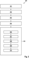
Zusammenfassend lässt sich sagen, dass gemäß verschiedenen Ausführungsformen ein Verfahren wie in
In 301 werden Demonstrationen durchgeführt (z. B. durch einen menschlichen Benutzer), wobei jede Demonstration die Handhabung eines Objekts vorführt.At 301, demonstrations are performed (e.g., by a human user), each demonstration demonstrating manipulation of an object.
In 302 wird für jede Demonstration mindestens ein Deskriptorbild aus dem Blickwinkel des Roboters auf das Objekt bereitgestellt (oder erhalten), wobei das Deskriptorbild Merkmalspunkte für Orte auf dem Objekt angibt. Die Deskriptorbilder könnten zum Beispiel durch ein DON aus Bildern erzeugt werden, die durch eine am Roboter montierte Kamera während der Demonstrationen aufgenommen wurden.At 302, for each demonstration, at least one descriptor image is provided (or obtained) from the robot's view of the object, the descriptor image indicating feature points for locations on the object. For example, the descriptor images could be generated by a DON from images captured by a robot-mounted camera during the demonstrations.
In 303 wird eine Menge von Merkmalspunkten (automatisch) aus den angegebenen Merkmalspunkten ausgewählt, wobei die Merkmalspunkte durch Suchen eines Optimums einer Zielfunktion ausgewählt werden, die ausgewählte Merkmalspunkte belohnt, die in den Deskriptorbildern sichtbar sind.In 303 a set of feature points is (automatically) selected from the given feature points, the feature points being selected by searching an optimum of an objective function rewarding selected feature points visible in the descriptor images.
In 304, ein Robotersteuerungsmodell (d. h. ein TP-HSMM), das die Demonstrationen verwendet, wobei das Robotersteuerungsmodell dazu ausgelegt ist, Steuerinformationen in Abhängigkeit von einer eingegebenen Objektpose auszugeben.In 304, a robot control model (i.e., a TP-HSMM) using the demonstrations, the robot control model being configured to output control information depending on an input object pose.
In 305, ein Roboter für eine Steuerszene mit dem Objekt durch
Bestimmen eines Deskriptorbildes des Objekts aus der Sicht des Roboters in 306,
Lokalisieren der ausgewählten Menge von Merkmalspunkten im Deskriptorbild des Objekts in 307,
Bestimmen der (z. B. euklidischen) Koordinaten der lokalisierten Merkmalspunkte für die Steuerszene in 308,
Schätzen einer Pose aus den ermittelten Koordinaten in 309 und
Steuern des Roboters, um das Objekt mittels des Robotersteuerungsmodells zu handhaben, wobei die geschätzte Pose dem Robotersteuerungsmodell als Eingabe in 310 zugeführt wird.In 305, a robot for a control scene with the object through
determining a descriptor image of the object as seen by the robot in 306,
locating the selected set of feature points in the object's descriptor image in 307,
determining the (e.g. Euclidean) coordinates of the located feature points for the control scene in 308,
Estimating a pose from the determined coordinates in 309 and
Controlling the robot to handle the object using the robot control model, the estimated pose being provided as input to the robot control model in 310 .
Der Ansatz von
Verschiedene Ausführungsformen können Bilddaten (d. h. digitale Bilder) aus verschiedenen visuellen Sensoren (Kameras) wie z. B. Video, Radar, LiDAR, Ultraschall, Wärmebildgebung, Bewegung, Sonar usw. empfangen und als Grundlage für die Deskriptorbilder verwenden.Various embodiments may receive image data (i.e., digital images) from various visual sensors (cameras), such as Receive video, radar, LiDAR, ultrasound, thermal imaging, motion, sonar, etc. and use it as a basis for the descriptor images.
Gemäß einer Ausführungsform ist das Verfahren computerimplementiert.According to one embodiment, the method is computer-implemented.
Auch wenn hier spezifische Ausführungsformen dargestellt und beschrieben sind, wird der Fachmann erkennen, dass eine Vielzahl von alternativen und/oder äquivalenten Ausführungsformen an die Stelle der spezifischen Ausführungsformen treten können, ohne dass der Anwendungsbereich der vorliegenden Erfindung verlassen wird. Diese Anmeldung soll alle Anpassungen oder Variationen der hier besprochenen spezifischen Ausführungsformen abdecken. Daher soll die Erfindung nur durch die Ansprüche und deren Entsprechungen eingeschränkt werden.While specific embodiments are illustrated and described herein, those skilled in the art will recognize that a variety of alternative and/or equivalent embodiments may be substituted for the specific embodiments without departing from the scope of the present invention. This application is intended to cover any adaptations or variations of the specific embodiments discussed herein. Therefore, the invention should be limited only by the claims and their equivalents.
Claims (11)
Priority Applications (4)
| Application Number | Priority Date | Filing Date | Title |
|---|---|---|---|
| DE102021211185.8A DE102021211185B4 (en) | 2021-10-05 | 2021-10-05 | Device and method for controlling a robot |
| US17/935,879 US20230107993A1 (en) | 2021-10-05 | 2022-09-27 | Device and method for controlling a robot |
| JP2022160018A JP2023055217A (en) | 2021-10-05 | 2022-10-04 | Device and method for controlling robot |
| CN202211220363.7A CN115933455A (en) | 2021-10-05 | 2022-10-08 | Apparatus and method for controlling a robot |
Applications Claiming Priority (1)
| Application Number | Priority Date | Filing Date | Title |
|---|---|---|---|
| DE102021211185.8A DE102021211185B4 (en) | 2021-10-05 | 2021-10-05 | Device and method for controlling a robot |
Publications (2)
| Publication Number | Publication Date |
|---|---|
| DE102021211185A1 true DE102021211185A1 (en) | 2023-04-06 |
| DE102021211185B4 DE102021211185B4 (en) | 2024-05-02 |
Family
ID=85570984
Family Applications (1)
| Application Number | Title | Priority Date | Filing Date |
|---|---|---|---|
| DE102021211185.8A Active DE102021211185B4 (en) | 2021-10-05 | 2021-10-05 | Device and method for controlling a robot |
Country Status (4)
| Country | Link |
|---|---|
| US (1) | US20230107993A1 (en) |
| JP (1) | JP2023055217A (en) |
| CN (1) | CN115933455A (en) |
| DE (1) | DE102021211185B4 (en) |
Families Citing this family (2)
| Publication number | Priority date | Publication date | Assignee | Title |
|---|---|---|---|---|
| EP4289566A3 (en) * | 2022-06-07 | 2024-01-03 | Canon Kabushiki Kaisha | Control method, control program, recording medium, method for manufacturing product, and system |
| US20230392931A1 (en) * | 2022-06-07 | 2023-12-07 | Objectvideo Labs, Llc | Robot pose estimation |
Citations (10)
| Publication number | Priority date | Publication date | Assignee | Title |
|---|---|---|---|---|
| DE10355283A1 (en) | 2002-11-21 | 2004-06-17 | Samsung Electronics Co., Ltd., Suwon | Hand / eye calibration procedure and associated point extraction procedure |
| DE102008020579B4 (en) | 2008-04-24 | 2014-07-31 | Fraunhofer-Gesellschaft zur Förderung der angewandten Forschung e.V. | Method for automatic object position detection and movement of a device relative to an object |
| US20150331415A1 (en) | 2014-05-16 | 2015-11-19 | Microsoft Corporation | Robotic task demonstration interface |
| DE102014106210B4 (en) | 2014-04-14 | 2015-12-17 | GM Global Technology Operations LLC (n. d. Ges. d. Staates Delaware) | Probabilistic person tracking using the Multi-View Association |
| US20200276703A1 (en) | 2017-09-20 | 2020-09-03 | Google Llc | Optimizing policy controllers for robotic agents using image embeddings |
| DE102020110650A1 (en) | 2019-06-27 | 2020-12-31 | Intel Corporation | Automatic robot perception programming through initiation learning |
| DE112019001507T5 (en) | 2018-03-23 | 2020-12-31 | Amazon Technologies, Inc. | OPTIMIZATION-BASED GRID DEFORMATION MODEL FOR SOFT MATERIALS |
| DE102019216229A1 (en) | 2019-10-07 | 2021-04-08 | Robert Bosch Gmbh | Apparatus and method for controlling a robotic device |
| DE102020127508A1 (en) | 2019-10-24 | 2021-04-29 | Nvidia Corporation | POSITION TRACKING OBJECTS IN HAND |
| DE102020128653A1 (en) | 2019-11-13 | 2021-05-20 | Nvidia Corporation | Determination of reaching for an object in disarray |
Family Cites Families (6)
| Publication number | Priority date | Publication date | Assignee | Title |
|---|---|---|---|---|
| JP5699697B2 (en) * | 2011-03-07 | 2015-04-15 | セイコーエプソン株式会社 | Robot device, position and orientation detection device, position and orientation detection program, and position and orientation detection method |
| US10974394B2 (en) * | 2016-05-19 | 2021-04-13 | Deep Learning Robotics Ltd. | Robot assisted object learning vision system |
| AU2019336263A1 (en) * | 2018-09-04 | 2021-04-08 | Fastbrick Ip Pty Ltd | Vision system for a robotic machine |
| DE102019216560B4 (en) * | 2019-10-28 | 2022-01-13 | Robert Bosch Gmbh | Method and device for training manipulation skills of a robot system |
| CN111055275B (en) * | 2019-12-04 | 2021-10-29 | 深圳市优必选科技股份有限公司 | Action imitation method, device, computer-readable storage medium, and robot |
| US11813749B2 (en) * | 2020-04-08 | 2023-11-14 | Fanuc Corporation | Robot teaching by human demonstration |
-
2021
- 2021-10-05 DE DE102021211185.8A patent/DE102021211185B4/en active Active
-
2022
- 2022-09-27 US US17/935,879 patent/US20230107993A1/en active Pending
- 2022-10-04 JP JP2022160018A patent/JP2023055217A/en active Pending
- 2022-10-08 CN CN202211220363.7A patent/CN115933455A/en active Pending
Patent Citations (10)
| Publication number | Priority date | Publication date | Assignee | Title |
|---|---|---|---|---|
| DE10355283A1 (en) | 2002-11-21 | 2004-06-17 | Samsung Electronics Co., Ltd., Suwon | Hand / eye calibration procedure and associated point extraction procedure |
| DE102008020579B4 (en) | 2008-04-24 | 2014-07-31 | Fraunhofer-Gesellschaft zur Förderung der angewandten Forschung e.V. | Method for automatic object position detection and movement of a device relative to an object |
| DE102014106210B4 (en) | 2014-04-14 | 2015-12-17 | GM Global Technology Operations LLC (n. d. Ges. d. Staates Delaware) | Probabilistic person tracking using the Multi-View Association |
| US20150331415A1 (en) | 2014-05-16 | 2015-11-19 | Microsoft Corporation | Robotic task demonstration interface |
| US20200276703A1 (en) | 2017-09-20 | 2020-09-03 | Google Llc | Optimizing policy controllers for robotic agents using image embeddings |
| DE112019001507T5 (en) | 2018-03-23 | 2020-12-31 | Amazon Technologies, Inc. | OPTIMIZATION-BASED GRID DEFORMATION MODEL FOR SOFT MATERIALS |
| DE102020110650A1 (en) | 2019-06-27 | 2020-12-31 | Intel Corporation | Automatic robot perception programming through initiation learning |
| DE102019216229A1 (en) | 2019-10-07 | 2021-04-08 | Robert Bosch Gmbh | Apparatus and method for controlling a robotic device |
| DE102020127508A1 (en) | 2019-10-24 | 2021-04-29 | Nvidia Corporation | POSITION TRACKING OBJECTS IN HAND |
| DE102020128653A1 (en) | 2019-11-13 | 2021-05-20 | Nvidia Corporation | Determination of reaching for an object in disarray |
Also Published As
| Publication number | Publication date |
|---|---|
| US20230107993A1 (en) | 2023-04-06 |
| CN115933455A (en) | 2023-04-07 |
| JP2023055217A (en) | 2023-04-17 |
| DE102021211185B4 (en) | 2024-05-02 |
Similar Documents
| Publication | Publication Date | Title |
|---|---|---|
| DE112019002310B4 (en) | PERFORMING A PEG IN HOLE TASK WITH AN UNKNOWN SLOPE | |
| DE102021204961B4 (en) | Method of controlling a robotic device | |
| DE102021107333A1 (en) | 3D POSITION ASSESSMENT WITH A 2D CAMERA | |
| DE102021204846B4 (en) | Method of controlling a robotic device | |
| DE102020214301A1 (en) | DEVICE AND METHOD FOR CONTROLLING A ROBOT TO PICK AN OBJECT IN DIFFERENT POSITIONS | |
| DE112018000332T5 (en) | SEAL VISUAL SLAM WITH PROBABILISTIC SURFEL MAP | |
| DE102020207085A1 (en) | METHOD OF CONTROLLING A ROBOT AND ROBOT CONTROL UNIT | |
| DE102022202144B4 (en) | Device and method for controlling a robot to perform a task | |
| DE102021204697B4 (en) | Method of controlling a robotic device | |
| DE102020214231A1 (en) | METHOD OF CONTROLLING A ROBOT DEVICE AND ROBOT CONTROLLER | |
| DE102020212658A1 (en) | Apparatus and method for controlling a robotic device | |
| DE102022203410B4 (en) | Method for controlling a robot device | |
| DE102021211185B4 (en) | Device and method for controlling a robot | |
| DE102021202340A1 (en) | METHOD OF CONTROLLING A ROBOT TO PICK AND INSPECT AN OBJECT AND ROBOT CONTROL DEVICE | |
| DE102021107479A1 (en) | CAPTURING A THREE-DIMENSIONAL POSE BY MULTIPLE 2D CAMERAS | |
| DE102020214300A1 (en) | DEVICE AND METHOD FOR TRAINING A MACHINE LEARNING MODEL FOR RECOGNIZING AN OBJECT TOPOLOGY OF AN OBJECT FROM AN IMAGE OF THE OBJECT | |
| DE102022202142B3 (en) | Device and method for training a machine learning model for deriving a motion vector for a robot from image data | |
| DE102021202759B4 (en) | Apparatus and method for training a machine learning model for controlling a robot | |
| DE102023201140B4 (en) | Device and method for controlling a robot device | |
| DE102021209761A1 (en) | Procedure for training a control strategy | |
| DE102021212906A1 (en) | Method of controlling an agent | |
| DE102023207208A1 (en) | Method for training a machine learning model for controlling a robot to manipulate an object | |
| DE102022206274B4 (en) | Method for controlling a robot for manipulating, in particular picking up, an object | |
| DE102022207847A1 (en) | Method for controlling a robot for manipulating, in particular picking up, an object | |
| DE102022202145A1 (en) | Robot and method for controlling a robot |
Legal Events
| Date | Code | Title | Description |
|---|---|---|---|
| R163 | Identified publications notified | ||
| R012 | Request for examination validly filed | ||
| R016 | Response to examination communication | ||
| R018 | Grant decision by examination section/examining division | ||
| R020 | Patent grant now final |