DE102021207190A1 - Method for controlling a tank device and tank device for storing a gaseous medium - Google Patents
Method for controlling a tank device and tank device for storing a gaseous medium Download PDFInfo
- Publication number
- DE102021207190A1 DE102021207190A1 DE102021207190.2A DE102021207190A DE102021207190A1 DE 102021207190 A1 DE102021207190 A1 DE 102021207190A1 DE 102021207190 A DE102021207190 A DE 102021207190A DE 102021207190 A1 DE102021207190 A1 DE 102021207190A1
- Authority
- DE
- Germany
- Prior art keywords
- tank
- tank device
- valve
- gaseous medium
- containers
- Prior art date
- Legal status (The legal status is an assumption and is not a legal conclusion. Google has not performed a legal analysis and makes no representation as to the accuracy of the status listed.)
- Pending
Links
Images
Classifications
-
- F—MECHANICAL ENGINEERING; LIGHTING; HEATING; WEAPONS; BLASTING
- F17—STORING OR DISTRIBUTING GASES OR LIQUIDS
- F17C—VESSELS FOR CONTAINING OR STORING COMPRESSED, LIQUEFIED OR SOLIDIFIED GASES; FIXED-CAPACITY GAS-HOLDERS; FILLING VESSELS WITH, OR DISCHARGING FROM VESSELS, COMPRESSED, LIQUEFIED, OR SOLIDIFIED GASES
- F17C13/00—Details of vessels or of the filling or discharging of vessels
- F17C13/04—Arrangement or mounting of valves
-
- F—MECHANICAL ENGINEERING; LIGHTING; HEATING; WEAPONS; BLASTING
- F17—STORING OR DISTRIBUTING GASES OR LIQUIDS
- F17C—VESSELS FOR CONTAINING OR STORING COMPRESSED, LIQUEFIED OR SOLIDIFIED GASES; FIXED-CAPACITY GAS-HOLDERS; FILLING VESSELS WITH, OR DISCHARGING FROM VESSELS, COMPRESSED, LIQUEFIED, OR SOLIDIFIED GASES
- F17C13/00—Details of vessels or of the filling or discharging of vessels
- F17C13/12—Arrangements or mounting of devices for preventing or minimising the effect of explosion ; Other safety measures
-
- F—MECHANICAL ENGINEERING; LIGHTING; HEATING; WEAPONS; BLASTING
- F17—STORING OR DISTRIBUTING GASES OR LIQUIDS
- F17C—VESSELS FOR CONTAINING OR STORING COMPRESSED, LIQUEFIED OR SOLIDIFIED GASES; FIXED-CAPACITY GAS-HOLDERS; FILLING VESSELS WITH, OR DISCHARGING FROM VESSELS, COMPRESSED, LIQUEFIED, OR SOLIDIFIED GASES
- F17C13/00—Details of vessels or of the filling or discharging of vessels
- F17C13/08—Mounting arrangements for vessels
- F17C13/084—Mounting arrangements for vessels for small-sized storage vessels, e.g. compressed gas cylinders or bottles, disposable gas vessels, vessels adapted for automotive use
-
- F—MECHANICAL ENGINEERING; LIGHTING; HEATING; WEAPONS; BLASTING
- F17—STORING OR DISTRIBUTING GASES OR LIQUIDS
- F17C—VESSELS FOR CONTAINING OR STORING COMPRESSED, LIQUEFIED OR SOLIDIFIED GASES; FIXED-CAPACITY GAS-HOLDERS; FILLING VESSELS WITH, OR DISCHARGING FROM VESSELS, COMPRESSED, LIQUEFIED, OR SOLIDIFIED GASES
- F17C7/00—Methods or apparatus for discharging liquefied, solidified, or compressed gases from pressure vessels, not covered by another subclass
-
- F—MECHANICAL ENGINEERING; LIGHTING; HEATING; WEAPONS; BLASTING
- F17—STORING OR DISTRIBUTING GASES OR LIQUIDS
- F17C—VESSELS FOR CONTAINING OR STORING COMPRESSED, LIQUEFIED OR SOLIDIFIED GASES; FIXED-CAPACITY GAS-HOLDERS; FILLING VESSELS WITH, OR DISCHARGING FROM VESSELS, COMPRESSED, LIQUEFIED, OR SOLIDIFIED GASES
- F17C2201/00—Vessel construction, in particular geometry, arrangement or size
- F17C2201/01—Shape
- F17C2201/0104—Shape cylindrical
-
- F—MECHANICAL ENGINEERING; LIGHTING; HEATING; WEAPONS; BLASTING
- F17—STORING OR DISTRIBUTING GASES OR LIQUIDS
- F17C—VESSELS FOR CONTAINING OR STORING COMPRESSED, LIQUEFIED OR SOLIDIFIED GASES; FIXED-CAPACITY GAS-HOLDERS; FILLING VESSELS WITH, OR DISCHARGING FROM VESSELS, COMPRESSED, LIQUEFIED, OR SOLIDIFIED GASES
- F17C2201/00—Vessel construction, in particular geometry, arrangement or size
- F17C2201/03—Orientation
- F17C2201/035—Orientation with substantially horizontal main axis
-
- F—MECHANICAL ENGINEERING; LIGHTING; HEATING; WEAPONS; BLASTING
- F17—STORING OR DISTRIBUTING GASES OR LIQUIDS
- F17C—VESSELS FOR CONTAINING OR STORING COMPRESSED, LIQUEFIED OR SOLIDIFIED GASES; FIXED-CAPACITY GAS-HOLDERS; FILLING VESSELS WITH, OR DISCHARGING FROM VESSELS, COMPRESSED, LIQUEFIED, OR SOLIDIFIED GASES
- F17C2205/00—Vessel construction, in particular mounting arrangements, attachments or identifications means
- F17C2205/01—Mounting arrangements
- F17C2205/0123—Mounting arrangements characterised by number of vessels
- F17C2205/013—Two or more vessels
- F17C2205/0134—Two or more vessels characterised by the presence of fluid connection between vessels
- F17C2205/0142—Two or more vessels characterised by the presence of fluid connection between vessels bundled in parallel
-
- F—MECHANICAL ENGINEERING; LIGHTING; HEATING; WEAPONS; BLASTING
- F17—STORING OR DISTRIBUTING GASES OR LIQUIDS
- F17C—VESSELS FOR CONTAINING OR STORING COMPRESSED, LIQUEFIED OR SOLIDIFIED GASES; FIXED-CAPACITY GAS-HOLDERS; FILLING VESSELS WITH, OR DISCHARGING FROM VESSELS, COMPRESSED, LIQUEFIED, OR SOLIDIFIED GASES
- F17C2205/00—Vessel construction, in particular mounting arrangements, attachments or identifications means
- F17C2205/03—Fluid connections, filters, valves, closure means or other attachments
- F17C2205/0302—Fittings, valves, filters, or components in connection with the gas storage device
- F17C2205/0323—Valves
- F17C2205/0326—Valves electrically actuated
-
- F—MECHANICAL ENGINEERING; LIGHTING; HEATING; WEAPONS; BLASTING
- F17—STORING OR DISTRIBUTING GASES OR LIQUIDS
- F17C—VESSELS FOR CONTAINING OR STORING COMPRESSED, LIQUEFIED OR SOLIDIFIED GASES; FIXED-CAPACITY GAS-HOLDERS; FILLING VESSELS WITH, OR DISCHARGING FROM VESSELS, COMPRESSED, LIQUEFIED, OR SOLIDIFIED GASES
- F17C2205/00—Vessel construction, in particular mounting arrangements, attachments or identifications means
- F17C2205/03—Fluid connections, filters, valves, closure means or other attachments
- F17C2205/0302—Fittings, valves, filters, or components in connection with the gas storage device
- F17C2205/0323—Valves
- F17C2205/0332—Safety valves or pressure relief valves
-
- F—MECHANICAL ENGINEERING; LIGHTING; HEATING; WEAPONS; BLASTING
- F17—STORING OR DISTRIBUTING GASES OR LIQUIDS
- F17C—VESSELS FOR CONTAINING OR STORING COMPRESSED, LIQUEFIED OR SOLIDIFIED GASES; FIXED-CAPACITY GAS-HOLDERS; FILLING VESSELS WITH, OR DISCHARGING FROM VESSELS, COMPRESSED, LIQUEFIED, OR SOLIDIFIED GASES
- F17C2221/00—Handled fluid, in particular type of fluid
- F17C2221/01—Pure fluids
- F17C2221/012—Hydrogen
-
- Y—GENERAL TAGGING OF NEW TECHNOLOGICAL DEVELOPMENTS; GENERAL TAGGING OF CROSS-SECTIONAL TECHNOLOGIES SPANNING OVER SEVERAL SECTIONS OF THE IPC; TECHNICAL SUBJECTS COVERED BY FORMER USPC CROSS-REFERENCE ART COLLECTIONS [XRACs] AND DIGESTS
- Y02—TECHNOLOGIES OR APPLICATIONS FOR MITIGATION OR ADAPTATION AGAINST CLIMATE CHANGE
- Y02E—REDUCTION OF GREENHOUSE GAS [GHG] EMISSIONS, RELATED TO ENERGY GENERATION, TRANSMISSION OR DISTRIBUTION
- Y02E60/00—Enabling technologies; Technologies with a potential or indirect contribution to GHG emissions mitigation
- Y02E60/30—Hydrogen technology
- Y02E60/32—Hydrogen storage
Landscapes
- Engineering & Computer Science (AREA)
- Mechanical Engineering (AREA)
- General Engineering & Computer Science (AREA)
- Filling Or Discharging Of Gas Storage Vessels (AREA)
Abstract
Verfahren zum Ansteuern einer Tankvorrichtung (1) zur Speicherung eines gasförmigen Mediums mit mindestens zwei Tankbehälter (2) und eine mit den Tankbehältern (2) verbindbare Zufuhrleitung (3), wobei jeder Tankbehälter (2) mindestens ein druckgesteuertes Steuerventil (5) aufweist, über welches Steuerventil (5) gasförmiges Medium aus der Tankvorrichtung (1) in die Zufuhrleitung (3) in Richtung eines Verbrauchersystems (40) strömt, gekennzeichnet durch die folgenden Schritte:
a. Gleichzeitiges Öffnen der Steuerventile (5) der Tankbehälter (2) in einem Abstand von Millisekunden während einer Versorgung des Verbrauchersystems (40), so dass gasförmiges Medium aus der Tankvorrichtung (1) über die Zufuhrleitung (3) in Richtung des Verbrauchersystems (40) geleitet wird.

a. Simultaneous opening of the control valves (5) of the tank containers (2) at an interval of milliseconds while the consumer system (40) is being supplied, so that gaseous medium is routed from the tank device (1) via the supply line (3) in the direction of the consumer system (40). will.
Description
Die Erfindung betrifft ein Verfahren zum Ansteuern einer Tankvorrichtung und eine Tankvorrichtung zur Speicherung eines gasförmigen Mediums, insbesondere Wasserstoff, beispielsweise zur Anwendung in Fahrzeugen mit Brennstoffzellenantrieb oder in Fahrzeugen mit einem Wasserstoffverbrenner als Antrieb.The invention relates to a method for controlling a tank device and a tank device for storing a gaseous medium, in particular hydrogen, for example for use in vehicles with a fuel cell drive or in vehicles with a hydrogen combustion engine as the drive.
Stand der TechnikState of the art
Die
Für die Sicherheitsvorkehrungen solch einer Einrichtung ist eine Vielzahl von Ventilen notwendig, wodurch die Komplexität des gesamten Gasspeichersystems sowie dessen Kosten erhöht werden.A large number of valves are necessary for the safety precautions of such a device, which increases the complexity of the entire gas storage system as well as its costs.
Vorteile der ErfindungAdvantages of the Invention
Das erfindungsgemäße Verfahren und die erfindungsgemäße Tankvorrichtung mit den kennzeichnenden Merkmalen des Anspruchs 1 und des Anspruchs 5 weisen demgegenüber den Vorteil auf, dass in einfacher Weise eine konstruktiv kompakte Tankvorrichtung mit gleichzeitiger Kostenersparnis realisiert wird.The method according to the invention and the tank device according to the invention with the characterizing features of claim 1 and
Für das erfindungsgemäße Verfahren zum Ansteuern einer Tankvorrichtung zur Speicherung eines gasförmigen Mediums sind mindestens zwei Tankbehälter und eine mit den Tankbehältern verbindbare Zufuhrleitung vorhanden, wobei jeder Tankbehälter mindestens ein druckgesteuertes Steuerventil aufweist. Über das Steuerventil strömt gasförmiges Medium aus der Tankvorrichtung in die Zufuhrleitung in Richtung eines Verbrauchersystems. Das erfindungsgemäße Verfahren weist den folgenden Schritt auf:
- Gleichzeitiges Öffnen der Steuerventile der Tankbehälter in einem Abstand von Millisekunden während einer Versorgung des Verbrauchersystems, so dass gasförmiges Medium aus der Tankvorrichtung über die Zufuhrleitung in Richtung des Verbrauchersystems geleitet wird.
- Simultaneous opening of the control valves of the tank containers at an interval of milliseconds while the consumer system is being supplied, so that gaseous medium is routed from the tank device via the supply line in the direction of the consumer system.
Durch das nahezu gleichzeitige Öffnen der Steuerventile, d.h. in einem Abstand von Millisekunden, kann der geforderte maximale Massestrom für die Tankvorrichtung realisiert werden, ohne die Tankvorrichtung und insbesondere die Querschnitte der Steuerventile zu groß und zu teuer gestalten zu müssen. Auch die dazugehörige Magnetbaugruppe als Ansteuerung der Steuerventile kann in konstruktiv kompakter Weise ausgelegt werden. Auf diese Weise kann eine kompakte und kostengünstige Tankvorrichtung realisiert werden.Due to the almost simultaneous opening of the control valves, i.e. at an interval of milliseconds, the required maximum mass flow for the tank device can be realized without having to make the tank device and in particular the cross sections of the control valves too large and too expensive. The associated magnet assembly for controlling the control valves can also be designed in a structurally compact manner. In this way, a compact and inexpensive tank device can be implemented.
In erster vorteilhafter Weiterbildung ist es vorgesehen, dass der Abstand des Öffnens der Steuerventile einen Bereich von 1 Millisekunde bis 20 Millisekunden umfasst. So kann beispielsweise die Belastung durch den Stromfluss auf ein Steuergerät der Tankvorrichtung minimiert werden.In a first advantageous development, it is provided that the interval between the opening of the control valves covers a range from 1 millisecond to 20 milliseconds. For example, the load caused by the current flow to a control device of the tank device can be minimized.
In weiterer Ausgestaltung der Erfindung ist es vorteilhaft vorgesehen, dass die Tankvorrichtung eine mit den Tankbehältern verbindbare Ventilleitung umfasst, in welcher Ventilleitung ein zentrales Schmelzsicherheitsventil angeordnet ist. Das Schmelzsicherheitsventil öffnet bei Überschreiten eines vorbestimmten Temperaturschwellwerts und leitet so das gasförmige Medium aus den Tankbehältern über die Ventilleitung in eine Umgebung. So ist sichergestellt, dass im Falle eines Wärmeeintrags auf die Tankvorrichtung, d.h. beispielsweise ein Brand, das gasförmige Medium aus den Tankbehältern geleitet und ein Bersten dieser verhindert wird.In a further embodiment of the invention, it is advantageously provided that the tank device comprises a valve line which can be connected to the tank containers and in which valve line a central melt safety valve is arranged. The melt safety valve opens when a predetermined temperature threshold value is exceeded and thus directs the gaseous medium from the tank containers via the valve line into an environment. This ensures that in the event of heat input to the tank device, i.e. a fire, for example, the gaseous medium is guided out of the tank containers and bursting is prevented.
In vorteilhafter Weiterbildung ist es vorgesehen, dass zwischen den jeweiligen Tankbehältern und der Ventilleitung jeweils ein Steuerventil angeordnet ist, durch welches Steuerventil eine fluidische Verbindung zwischen den Tankbehältern und der Ventilleitung gesteuert wird. Auf diese Weise kann das gasförmige Medium aus den Tankbehältern in die Ventilleitung abgeströmt werden oder durch Absperren des Steuerventils in dem jeweiligen Tankbehälter gespeichert bleiben. Letzteres ist insbesondere auch als Sicherheitsvorkehrung, beispielsweise bei einem Bruch der Ventilleitung von Vorteil.In an advantageous further development, provision is made for a control valve to be arranged between the respective tank containers and the valve line, by means of which control valve a fluidic connection between the tank containers and the valve line is controlled. In this way, the gaseous medium can flow out of the tank containers into the valve line or remain stored in the respective tank container by shutting off the control valve. The latter is particularly advantageous as a safety precaution, for example if the valve line breaks.
Die erfindungsgemäße Tankvorrichtung zur Speicherung eines gasförmigen Mediums, insbesondere Wasserstoff weist mindestens zwei Tankbehälter und eine mit den Tankbehältern verbindbare Zufuhrleitung auf. Jeder Tankbehälter umfasst mindestens ein druckgesteuertes Steuerventil, welches Steuerventil zwischen dem jeweiligen Tankbehälter und der Zufuhrleitung angeordnet ist. Die Zufuhrleitung ist mit einem Verbrauchersystem fluidisch verbunden, wobei die Tankvorrichtung ein Steuergerät aufweist, welches Steuergerät dazu eingerichtet ist, das zuvor beschriebene erfindungsgemäße Verfahren durchzuführen. So kann in konstruktiv kompakter und auf kostensparende Weise eine Tankvorrichtung zur Speicherung eines gasförmigen Mediums für verschiedene Verbrauchersysteme realisiert werden.The tank device according to the invention for storing a gaseous medium, in particular hydrogen, has at least two tank containers and a supply line that can be connected to the tank containers. Each tank contains at least one pressure-controlled control valve, which control valve is arranged between the respective tank and the supply line. The supply line is fluidically connected to a consumer system, with the tank device having a control unit, which control unit is set up to carry out the method according to the invention described above. A tank device for storing a gaseous medium for various consumer systems can thus be implemented in a structurally compact and cost-saving manner.
In vorteilhafter Weiterbildung ist es vorgesehen, dass das Steuerventil des jeweiligen Tankbehälters als Magnetventil ausgebildet ist. So ist eine einfache Ansteuerung möglich.In an advantageous development, it is provided that the control valve of the respective tank container ters is designed as a solenoid valve. In this way, simple control is possible.
In vorteilhafter Weiterbildung sind die Tankbehälter röhrenförmig ausgebildet. Vorteilhafterweise umfassen die Tankbehälter ein kohlefaserverstärktes Material. In an advantageous development, the tank containers are of tubular design. Advantageously, the tank containers comprise a carbon fiber reinforced material.
Durch die Geometrie und geeignete Wahl der Tankbehälter können diese in einfacher Weise an das gasförmige Medium und beispielsweise an ein Chassis eines Fahrzeugs angepasst werden.Due to the geometry and suitable choice of the tank containers, they can easily be adapted to the gaseous medium and, for example, to a chassis of a vehicle.
Weiterhin ist erfindungsgemäß ein Steuergerät vorhanden, welches dazu eingerichtet ist, das erfindungsgemäße Verfahren durchzuführen.Furthermore, according to the invention, there is a control unit which is set up to carry out the method according to the invention.
Die beschriebene Tankvorrichtung und das die Tankvorrichtung ansteuernde Verfahren eignen sich vorzugsweise in einem Brennstoffzellensystem zum Speichern eines gasförmigen Mediums, insbesondere Wasserstoff, für den Betrieb einer Brennstoffzelle.The tank device described and the method controlling the tank device are preferably suitable in a fuel cell system for storing a gaseous medium, in particular hydrogen, for the operation of a fuel cell.
In vorteilhaften Verwendungen kann die Tankvorrichtung und das erfindungsgemäße Verfahren in Fahrzeugen mit einem Brennstoffzellenantrieb verwendet werden.In advantageous uses, the tank device and the method according to the invention can be used in vehicles with a fuel cell drive.
In vorteilhaften Verwendungen kann die Tankvorrichtung und das erfindungsgemäße Verfahren in Fahrzeugen mit einem Wasserstoffantrieb verwendet werden, beispielsweise in einem Fahrzeug mit Wasserstoff-Verbrenner als Antrieb.In advantageous uses, the tank device and the method according to the invention can be used in vehicles with a hydrogen drive, for example in a vehicle with a hydrogen combustion engine as the drive.
Figurenlistecharacter list
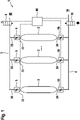
In der Zeichnung ist ein Ausführungsbeispiel einer Tankvorrichtung mit einem erfindungsgemäßen Verfahren zum Ansteuern der Tankvorrichtung dargestellt. Es zeigt in
- Fig. leine Draufsicht eines möglichen Ausführungsbeispiels einer Tankvorrichtung mit einem erfindungsgemäßen Verfahren.
- 1 shows a top view of a possible exemplary embodiment of a tank device with a method according to the invention.
Beschreibung des AusführungsbeispielsDescription of the embodiment
In der
Weiterhin ist jeder Tankbehälter 2 an einem ersten Ende über eine Abzweigung 26 mit einer Zufuhrleitung 3 verbunden, wobei in der Abzweigung 26 der Zufuhrleitung 3 ein Steuerventil 5 angeordnet ist. Somit weist jeder Tankbehälter 2 ein Steuerventil 5 auf, über welches das gasförmige Medium aus dem Tankbehälter 2 in Richtung der Zufuhrleitung 3 ableitbar ist. Die Steuerventile 5 sind beispielsweise durch einen Elektromagneten ansteuerbar.Furthermore, each
In der Zufuhrleitung 3 ist weiterhin ein Druckregelventil 8 angeordnet, welches hier als Magnetventil ausgebildet ist. Das Druckregelventil 8 steuert so mit Hilfe eines Elektromagneten die Wasserstoffzufuhr aus der Tankvorrichtung 1 in Richtung eines Verbrauchersystems 40, beispielsweise eines Brennstoffzellensystems oder eines Wasserstoffverbrennersystems. Das Druckregelventil 8 reguliert hierbei auch den Druck des gasförmigen Mediums, insbesondere als Druckminderung des gasförmigen Mediums für dessen Bereitstellung für das Verbrauchersystem 40.In the
Weiterhin ist jeder Tankbehälter 2 in einer alternativen Anordnung an einem anderen Ende 24 mit einer Ventilleitung 6 verbunden, wobei zwischen jedem einzelnen Tankbehälter 2 und der Ventilleitung 6 ein weiteres Steuerventil 50 angeordnet ist. Im normalen Betriebszustand sind auch die weiteren Steuerventile 50 geöffnet, so dass eine Verbindung zwischen dem Innern des Tankbehälters 2 und der Ventilleitung 6 geöffnet ist. In der Ventilleitung 6 ist ein zentrales Schmelzsicherheitsventil 10 angeordnet. Das Schmelzsicherheitsventil 10 ist im Normalfall geschlossen und öffnet lediglich im Brandfall oder bei Überschreitung eines vorbestimmten Temperaturschwellwertes von beispielsweise 105°C, so dass der Wasserstoff aus den Tankbehältern 2 über die Ventilleitung 6 in eine Umgebung 30 ausgeleitet werden kann und eine mögliche Explosion der Tankbehälter 2 aufgrund eines zu hohen Drucks unterbunden wird.Furthermore, in an alternative arrangement, each
Die Steuerventile 5, 50 sind jeweils an den Enden 22, 24 der Tankbehälter 2 angeordnet, so dass im Falle eines Unfalls der Tankvorrichtung 1 oder bei einem Bruch der ersten Leitung 3 und/oder der Ventilleitung 6 die Steuerventile 5, 50 schließen und das gasförmige Medium nicht aus dem Tankbehälter 2 austreten kann.The
Weiterhin umfasst die Tankvorrichtung 1 ein Steuergerät 80, welches mit den Steuerventilen 5, 50 und dem Schmelzsicherheitsventil 10 verbunden ist. Das Steuergerät 80 weist auch eine Schnittstelle zu einer nicht gezeigten Steuereinheit des Verbrauchersystems 40 auf.Furthermore, the tank device 1 includes a
Soll nun dem Verbrauchersystem 40 gasförmiges Medium, beispielsweise Wasserstoff, zugeführt werden, werden alle Steuerventile 5 der Tankbehälter 2 über den jeweiligen Elektromagneten des jeweiligen Steuerventils 5 mittels des Steuergeräts 80 gleichzeitig in einem Abstand von Millisekunden angesteuert und geöffnet und das gasförmige Medium aus der Tankvorrichtung 1 über die Zufuhrleitung 3 in Richtung des Verbrauchersystems 40 geleitet. Das heißt, die Steuerventile 5 werden in einem Abstand von 1 Millisekunde bis 20 Millisekunden nacheinander geöffnet. Dadurch ist eine Realisierung von geringen geometrischen Dimensionen der Steuerventilquerschnitte trotz beispielsweise maximalem Massestroms möglich. Weiterhin kann so beispielsweise ein Brennstoffzellensystem als Verbrauchersystem 40 mit Brennstoff, beispielsweise Wasserstoff, versorgt werden.If gaseous medium, for example hydrogen, is now to be supplied to the consumer system 40, all
Weiterhin eignet sich die Tankvorrichtung 1 und das genannte Verfahren dazu auch einem brennstoffzellenbetriebenen Fahrzeug für die Bereitstellung des Brennstoffs, beispielsweise Wasserstoff, oder in einem wasserstoffbetriebenen Fahrzeug für die Bereitstellung von Wasserstoff.Furthermore, the tank device 1 and the method mentioned are also suitable for providing the fuel, for example hydrogen, in a fuel cell-powered vehicle, or for providing hydrogen in a hydrogen-powered vehicle.
ZITATE ENTHALTEN IN DER BESCHREIBUNGQUOTES INCLUDED IN DESCRIPTION
Diese Liste der vom Anmelder aufgeführten Dokumente wurde automatisiert erzeugt und ist ausschließlich zur besseren Information des Lesers aufgenommen. Die Liste ist nicht Bestandteil der deutschen Patent- bzw. Gebrauchsmusteranmeldung. Das DPMA übernimmt keinerlei Haftung für etwaige Fehler oder Auslassungen.This list of documents cited by the applicant was generated automatically and is included solely for the better information of the reader. The list is not part of the German patent or utility model application. The DPMA assumes no liability for any errors or omissions.
Zitierte PatentliteraturPatent Literature Cited
- DE 102017212485 A1 [0002]DE 102017212485 A1 [0002]
Claims (12)
Priority Applications (5)
| Application Number | Priority Date | Filing Date | Title |
|---|---|---|---|
| DE102021207190.2A DE102021207190A1 (en) | 2021-07-08 | 2021-07-08 | Method for controlling a tank device and tank device for storing a gaseous medium |
| PCT/EP2022/064706 WO2023280471A1 (en) | 2021-07-08 | 2022-05-31 | Method for actuating a tank device, and tank device for storing a gaseous medium |
| CN202280048312.2A CN117616224A (en) | 2021-07-08 | 2022-05-31 | Method for operating a tank device and tank device for storing gaseous media |
| US18/574,832 US12590677B2 (en) | 2021-07-08 | 2022-05-31 | Method for actuating a tank device, and tank device for storing a gaseous medium |
| EP22729247.1A EP4367430B1 (en) | 2021-07-08 | 2022-05-31 | Method for actuating a tank device, and tank device for storing a gaseous medium |
Applications Claiming Priority (1)
| Application Number | Priority Date | Filing Date | Title |
|---|---|---|---|
| DE102021207190.2A DE102021207190A1 (en) | 2021-07-08 | 2021-07-08 | Method for controlling a tank device and tank device for storing a gaseous medium |
Publications (1)
| Publication Number | Publication Date |
|---|---|
| DE102021207190A1 true DE102021207190A1 (en) | 2023-01-12 |
Family
ID=82016214
Family Applications (1)
| Application Number | Title | Priority Date | Filing Date |
|---|---|---|---|
| DE102021207190.2A Pending DE102021207190A1 (en) | 2021-07-08 | 2021-07-08 | Method for controlling a tank device and tank device for storing a gaseous medium |
Country Status (5)
| Country | Link |
|---|---|
| US (1) | US12590677B2 (en) |
| EP (1) | EP4367430B1 (en) |
| CN (1) | CN117616224A (en) |
| DE (1) | DE102021207190A1 (en) |
| WO (1) | WO2023280471A1 (en) |
Cited By (4)
| Publication number | Priority date | Publication date | Assignee | Title |
|---|---|---|---|---|
| DE102023204705A1 (en) | 2023-05-19 | 2024-11-21 | Robert Bosch Gesellschaft mit beschränkter Haftung | Storage system for storing a gaseous medium, preferably hydrogen, fuel cell system, hydrogen combustion engine system, fuel cell-powered vehicle, hydrogen-powered vehicle |
| DE102023207732A1 (en) | 2023-08-11 | 2025-02-13 | Robert Bosch Gesellschaft mit beschränkter Haftung | tank system for hydrogen applications, fuel cell assembly, hydrogen internal combustion engine system, fuel cell powered vehicle, hydrogen powered vehicle |
| DE102023207760A1 (en) | 2023-08-11 | 2025-02-13 | Robert Bosch Gesellschaft mit beschränkter Haftung | Storage system for storing a gaseous medium, preferably hydrogen, fuel cell system, hydrogen combustion engine system, fuel cell-powered vehicle, hydrogen-powered vehicle |
| WO2025103698A1 (en) | 2023-11-17 | 2025-05-22 | Robert Bosch Gmbh | Storage system for storing a gaseous medium, preferably hydrogen, fuel cell system, hydrogen combustion engine system, fuel cell-powered vehicle, hydrogen-powered vehicle |
Families Citing this family (6)
| Publication number | Priority date | Publication date | Assignee | Title |
|---|---|---|---|---|
| DE102020213268A1 (en) * | 2020-10-21 | 2022-04-21 | Robert Bosch Gesellschaft mit beschränkter Haftung | Tank device for temperature pressure relief of a fuel cell tank |
| DE102021207187A1 (en) * | 2021-07-08 | 2023-01-12 | Robert Bosch Gesellschaft mit beschränkter Haftung | Tank device for storing a gaseous medium |
| WO2024102662A1 (en) * | 2022-11-08 | 2024-05-16 | Nikola Corporation | Systems and methods for monitoring hydrogen fuel |
| CN116658814B (en) * | 2023-04-17 | 2024-04-16 | 东风汽车集团股份有限公司 | Medium storage system and vehicle |
| CN117028848B (en) * | 2023-07-21 | 2025-11-21 | 厚普清洁能源集团能源装备有限公司 | Control method for charging and discharging sequence of hydrogen storage bottle group of hydrogen adding station |
| US20250314353A1 (en) * | 2024-04-09 | 2025-10-09 | Caterpillar Inc. | Hydrogen defuel system for hydrogen tanks |
Citations (1)
| Publication number | Priority date | Publication date | Assignee | Title |
|---|---|---|---|---|
| DE102017212485A1 (en) | 2017-07-20 | 2019-01-24 | Robert Bosch Gmbh | Device for storing compressed fluids |
Family Cites Families (6)
| Publication number | Priority date | Publication date | Assignee | Title |
|---|---|---|---|---|
| WO2005010427A1 (en) * | 2003-07-25 | 2005-02-03 | Toyota Jidosha Kabushiki Kaisha | Gas supply system |
| DE102009024794A1 (en) * | 2009-06-10 | 2010-12-16 | Daimler Ag | Hydrogen tank for use in motor vehicle, has multi-shell structure with tank volumes enclosed from each other, where higher and lower filling pressures of tank volumes are decreased outwardly, and tank walls exhibiting different shapes |
| DE102014000713A1 (en) * | 2014-01-18 | 2015-07-23 | Daimler Ag | Method for removing high pressure stored gas |
| DE102018209057A1 (en) | 2018-06-07 | 2019-12-12 | Robert Bosch Gmbh | Tank device for temperature pressure relief of a fuel cell tank |
| DE102020001257A1 (en) * | 2020-02-26 | 2021-08-26 | Man Truck & Bus Se | Device for fuel supply and vehicle with such a device |
| DE102020212078A1 (en) * | 2020-11-13 | 2022-05-19 | Robert Bosch Gesellschaft mit beschränkter Haftung | Pressure storage device for storing a medium and method for operating a pressure storage device |
-
2021
- 2021-07-08 DE DE102021207190.2A patent/DE102021207190A1/en active Pending
-
2022
- 2022-05-31 EP EP22729247.1A patent/EP4367430B1/en active Active
- 2022-05-31 WO PCT/EP2022/064706 patent/WO2023280471A1/en not_active Ceased
- 2022-05-31 CN CN202280048312.2A patent/CN117616224A/en active Pending
- 2022-05-31 US US18/574,832 patent/US12590677B2/en active Active
Patent Citations (1)
| Publication number | Priority date | Publication date | Assignee | Title |
|---|---|---|---|---|
| DE102017212485A1 (en) | 2017-07-20 | 2019-01-24 | Robert Bosch Gmbh | Device for storing compressed fluids |
Cited By (4)
| Publication number | Priority date | Publication date | Assignee | Title |
|---|---|---|---|---|
| DE102023204705A1 (en) | 2023-05-19 | 2024-11-21 | Robert Bosch Gesellschaft mit beschränkter Haftung | Storage system for storing a gaseous medium, preferably hydrogen, fuel cell system, hydrogen combustion engine system, fuel cell-powered vehicle, hydrogen-powered vehicle |
| DE102023207732A1 (en) | 2023-08-11 | 2025-02-13 | Robert Bosch Gesellschaft mit beschränkter Haftung | tank system for hydrogen applications, fuel cell assembly, hydrogen internal combustion engine system, fuel cell powered vehicle, hydrogen powered vehicle |
| DE102023207760A1 (en) | 2023-08-11 | 2025-02-13 | Robert Bosch Gesellschaft mit beschränkter Haftung | Storage system for storing a gaseous medium, preferably hydrogen, fuel cell system, hydrogen combustion engine system, fuel cell-powered vehicle, hydrogen-powered vehicle |
| WO2025103698A1 (en) | 2023-11-17 | 2025-05-22 | Robert Bosch Gmbh | Storage system for storing a gaseous medium, preferably hydrogen, fuel cell system, hydrogen combustion engine system, fuel cell-powered vehicle, hydrogen-powered vehicle |
Also Published As
| Publication number | Publication date |
|---|---|
| US20240302002A1 (en) | 2024-09-12 |
| EP4367430A1 (en) | 2024-05-15 |
| WO2023280471A1 (en) | 2023-01-12 |
| EP4367430B1 (en) | 2025-10-08 |
| CN117616224A (en) | 2024-02-27 |
| US12590677B2 (en) | 2026-03-31 |
Similar Documents
| Publication | Publication Date | Title |
|---|---|---|
| DE102021207190A1 (en) | Method for controlling a tank device and tank device for storing a gaseous medium | |
| EP3803191B1 (en) | Tank device for the temperature pressure relief of a fuel cell tank | |
| DE102018221602A1 (en) | Tank device for storing a gaseous medium | |
| DE102006017541B4 (en) | Method for discharging high-pressure storage containers | |
| DE102018215380A1 (en) | Valve device for a gaseous medium and tank device for storing a gaseous medium | |
| DE102020108176A1 (en) | Fuel supply system and motor vehicle | |
| EP3961083A1 (en) | Tank system | |
| DE102020213268A1 (en) | Tank device for temperature pressure relief of a fuel cell tank | |
| DE102021205684A1 (en) | Shut-off valve for hydrogen tank systems, hydrogen tank system and use of a shut-off valve in a hydrogen tank system | |
| DE102008063563A1 (en) | Fuel e.g. liquid hydrogen, supply system for passenger car, has cryotank with multiple connections for guiding and diverting fuel, and manifold valve exhibiting pre-defined shut-off position, filling position and withdrawal position | |
| DE102015221717A1 (en) | Solenoid valve and method for controlling the solenoid valve | |
| DE102022208072A1 (en) | Valve assembly for a fuel gas tank, fuel gas tank with valve assembly and fuel gas tank system | |
| DE102020213577A1 (en) | Tank device for storing a gaseous medium | |
| DE102021104334A1 (en) | Connection element, pressure vessel assembly and motor vehicle | |
| DE102024116968A1 (en) | On-Tank Valve | |
| DE102019211730A1 (en) | Tank device for storing a gaseous medium | |
| EP4409195B1 (en) | Cryogenic tank | |
| DE102022211716A1 (en) | Valve assembly for a fuel gas tank, fuel gas tank with valve assembly | |
| DE102019217064A1 (en) | Tank device for relieving the temperature of a fuel cell tank | |
| DE102020201364A1 (en) | Tank device for storing a gaseous medium | |
| DE102019210515A1 (en) | Tank device for storing a gaseous medium | |
| DE102020215929A1 (en) | Tank device for temperature pressure relief of a hydrogen tank | |
| DE102017113055A1 (en) | Gas pressure regulator | |
| DE102021200470A1 (en) | Compressed gas container device for storing a gaseous medium | |
| DE102021115940A1 (en) | Valve device |