DE102021125561A1 - Medical Fluid Container - Google Patents
Medical Fluid Container Download PDFInfo
- Publication number
- DE102021125561A1 DE102021125561A1 DE102021125561.9A DE102021125561A DE102021125561A1 DE 102021125561 A1 DE102021125561 A1 DE 102021125561A1 DE 102021125561 A DE102021125561 A DE 102021125561A DE 102021125561 A1 DE102021125561 A1 DE 102021125561A1
- Authority
- DE
- Germany
- Prior art keywords
- container
- medical fluid
- fluid container
- inner channel
- die
- Prior art date
- Legal status (The legal status is an assumption and is not a legal conclusion. Google has not performed a legal analysis and makes no representation as to the accuracy of the status listed.)
- Pending
Links
Images

Classifications
-
- B—PERFORMING OPERATIONS; TRANSPORTING
- B65—CONVEYING; PACKING; STORING; HANDLING THIN OR FILAMENTARY MATERIAL
- B65D—CONTAINERS FOR STORAGE OR TRANSPORT OF ARTICLES OR MATERIALS, e.g. BAGS, BARRELS, BOTTLES, BOXES, CANS, CARTONS, CRATES, DRUMS, JARS, TANKS, HOPPERS, FORWARDING CONTAINERS; ACCESSORIES, CLOSURES, OR FITTINGS THEREFOR; PACKAGING ELEMENTS; PACKAGES
- B65D1/00—Rigid or semi-rigid containers having bodies formed in one piece, e.g. by casting metallic material, by moulding plastics, by blowing vitreous material, by throwing ceramic material, by moulding pulped fibrous material or by deep-drawing operations performed on sheet material
- B65D1/02—Bottles or similar containers with necks or like restricted apertures, designed for pouring contents
- B65D1/0223—Bottles or similar containers with necks or like restricted apertures, designed for pouring contents characterised by shape
- B65D1/023—Neck construction
- B65D1/0246—Closure retaining means, e.g. beads, screw-threads
-
- A—HUMAN NECESSITIES
- A61—MEDICAL OR VETERINARY SCIENCE; HYGIENE
- A61J—CONTAINERS SPECIALLY ADAPTED FOR MEDICAL OR PHARMACEUTICAL PURPOSES; DEVICES OR METHODS SPECIALLY ADAPTED FOR BRINGING PHARMACEUTICAL PRODUCTS INTO PARTICULAR PHYSICAL OR ADMINISTERING FORMS; DEVICES FOR ADMINISTERING FOOD OR MEDICINES ORALLY; BABY COMFORTERS; DEVICES FOR RECEIVING SPITTLE
- A61J1/00—Containers specially adapted for medical or pharmaceutical purposes
- A61J1/14—Details; Accessories therefor
- A61J1/1412—Containers with closing means, e.g. caps
- A61J1/1418—Threaded type
-
- B—PERFORMING OPERATIONS; TRANSPORTING
- B29—WORKING OF PLASTICS; WORKING OF SUBSTANCES IN A PLASTIC STATE IN GENERAL
- B29C—SHAPING OR JOINING OF PLASTICS; SHAPING OF MATERIAL IN A PLASTIC STATE, NOT OTHERWISE PROVIDED FOR; AFTER-TREATMENT OF THE SHAPED PRODUCTS, e.g. REPAIRING
- B29C49/00—Blow-moulding, i.e. blowing a preform or parison to a desired shape within a mould; Apparatus therefor
- B29C49/02—Combined blow-moulding and manufacture of the preform or the parison
- B29C49/04—Extrusion blow-moulding
-
- B—PERFORMING OPERATIONS; TRANSPORTING
- B29—WORKING OF PLASTICS; WORKING OF SUBSTANCES IN A PLASTIC STATE IN GENERAL
- B29C—SHAPING OR JOINING OF PLASTICS; SHAPING OF MATERIAL IN A PLASTIC STATE, NOT OTHERWISE PROVIDED FOR; AFTER-TREATMENT OF THE SHAPED PRODUCTS, e.g. REPAIRING
- B29C49/00—Blow-moulding, i.e. blowing a preform or parison to a desired shape within a mould; Apparatus therefor
- B29C49/42—Component parts, details or accessories; Auxiliary operations
- B29C49/58—Blowing means
-
- B—PERFORMING OPERATIONS; TRANSPORTING
- B29—WORKING OF PLASTICS; WORKING OF SUBSTANCES IN A PLASTIC STATE IN GENERAL
- B29C—SHAPING OR JOINING OF PLASTICS; SHAPING OF MATERIAL IN A PLASTIC STATE, NOT OTHERWISE PROVIDED FOR; AFTER-TREATMENT OF THE SHAPED PRODUCTS, e.g. REPAIRING
- B29C49/00—Blow-moulding, i.e. blowing a preform or parison to a desired shape within a mould; Apparatus therefor
- B29C49/42—Component parts, details or accessories; Auxiliary operations
- B29C49/76—Neck calibration
- B29C49/761—Forming threads, e.g. shaping neck thread between blowing means and mould
-
- B—PERFORMING OPERATIONS; TRANSPORTING
- B65—CONVEYING; PACKING; STORING; HANDLING THIN OR FILAMENTARY MATERIAL
- B65D—CONTAINERS FOR STORAGE OR TRANSPORT OF ARTICLES OR MATERIALS, e.g. BAGS, BARRELS, BOTTLES, BOXES, CANS, CARTONS, CRATES, DRUMS, JARS, TANKS, HOPPERS, FORWARDING CONTAINERS; ACCESSORIES, CLOSURES, OR FITTINGS THEREFOR; PACKAGING ELEMENTS; PACKAGES
- B65D1/00—Rigid or semi-rigid containers having bodies formed in one piece, e.g. by casting metallic material, by moulding plastics, by blowing vitreous material, by throwing ceramic material, by moulding pulped fibrous material or by deep-drawing operations performed on sheet material
- B65D1/02—Bottles or similar containers with necks or like restricted apertures, designed for pouring contents
- B65D1/0223—Bottles or similar containers with necks or like restricted apertures, designed for pouring contents characterised by shape
- B65D1/023—Neck construction
-
- B—PERFORMING OPERATIONS; TRANSPORTING
- B29—WORKING OF PLASTICS; WORKING OF SUBSTANCES IN A PLASTIC STATE IN GENERAL
- B29C—SHAPING OR JOINING OF PLASTICS; SHAPING OF MATERIAL IN A PLASTIC STATE, NOT OTHERWISE PROVIDED FOR; AFTER-TREATMENT OF THE SHAPED PRODUCTS, e.g. REPAIRING
- B29C49/00—Blow-moulding, i.e. blowing a preform or parison to a desired shape within a mould; Apparatus therefor
- B29C49/42—Component parts, details or accessories; Auxiliary operations
- B29C49/48—Moulds
- B29C2049/4879—Moulds characterised by mould configurations
- B29C2049/4894—With at least a part of the mould cavity formed by a cylindrical mould
-
- B—PERFORMING OPERATIONS; TRANSPORTING
- B29—WORKING OF PLASTICS; WORKING OF SUBSTANCES IN A PLASTIC STATE IN GENERAL
- B29C—SHAPING OR JOINING OF PLASTICS; SHAPING OF MATERIAL IN A PLASTIC STATE, NOT OTHERWISE PROVIDED FOR; AFTER-TREATMENT OF THE SHAPED PRODUCTS, e.g. REPAIRING
- B29C49/00—Blow-moulding, i.e. blowing a preform or parison to a desired shape within a mould; Apparatus therefor
- B29C49/42—Component parts, details or accessories; Auxiliary operations
- B29C49/58—Blowing means
- B29C2049/5862—Drive means therefore
-
- B—PERFORMING OPERATIONS; TRANSPORTING
- B29—WORKING OF PLASTICS; WORKING OF SUBSTANCES IN A PLASTIC STATE IN GENERAL
- B29C—SHAPING OR JOINING OF PLASTICS; SHAPING OF MATERIAL IN A PLASTIC STATE, NOT OTHERWISE PROVIDED FOR; AFTER-TREATMENT OF THE SHAPED PRODUCTS, e.g. REPAIRING
- B29C49/00—Blow-moulding, i.e. blowing a preform or parison to a desired shape within a mould; Apparatus therefor
- B29C49/42—Component parts, details or accessories; Auxiliary operations
- B29C49/58—Blowing means
- B29C2049/5893—Mounting, exchanging or centering blowing means
- B29C2049/5896—Centering means therefore
-
- B—PERFORMING OPERATIONS; TRANSPORTING
- B29—WORKING OF PLASTICS; WORKING OF SUBSTANCES IN A PLASTIC STATE IN GENERAL
- B29C—SHAPING OR JOINING OF PLASTICS; SHAPING OF MATERIAL IN A PLASTIC STATE, NOT OTHERWISE PROVIDED FOR; AFTER-TREATMENT OF THE SHAPED PRODUCTS, e.g. REPAIRING
- B29C2949/00—Indexing scheme relating to blow-moulding
- B29C2949/07—Preforms or parisons characterised by their configuration
- B29C2949/071—Preforms or parisons characterised by their configuration the preform being a tube, i.e. with both ends open
-
- B—PERFORMING OPERATIONS; TRANSPORTING
- B29—WORKING OF PLASTICS; WORKING OF SUBSTANCES IN A PLASTIC STATE IN GENERAL
- B29C—SHAPING OR JOINING OF PLASTICS; SHAPING OF MATERIAL IN A PLASTIC STATE, NOT OTHERWISE PROVIDED FOR; AFTER-TREATMENT OF THE SHAPED PRODUCTS, e.g. REPAIRING
- B29C2949/00—Indexing scheme relating to blow-moulding
- B29C2949/07—Preforms or parisons characterised by their configuration
- B29C2949/076—Preforms or parisons characterised by their configuration characterised by the shape
- B29C2949/0768—Preforms or parisons characterised by their configuration characterised by the shape characterised by the shape of specific parts of preform
- B29C2949/077—Preforms or parisons characterised by their configuration characterised by the shape characterised by the shape of specific parts of preform characterised by the neck
- B29C2949/0772—Closure retaining means
- B29C2949/0773—Threads
-
- B—PERFORMING OPERATIONS; TRANSPORTING
- B29—WORKING OF PLASTICS; WORKING OF SUBSTANCES IN A PLASTIC STATE IN GENERAL
- B29C—SHAPING OR JOINING OF PLASTICS; SHAPING OF MATERIAL IN A PLASTIC STATE, NOT OTHERWISE PROVIDED FOR; AFTER-TREATMENT OF THE SHAPED PRODUCTS, e.g. REPAIRING
- B29C2949/00—Indexing scheme relating to blow-moulding
- B29C2949/07—Preforms or parisons characterised by their configuration
- B29C2949/076—Preforms or parisons characterised by their configuration characterised by the shape
- B29C2949/0768—Preforms or parisons characterised by their configuration characterised by the shape characterised by the shape of specific parts of preform
- B29C2949/077—Preforms or parisons characterised by their configuration characterised by the shape characterised by the shape of specific parts of preform characterised by the neck
- B29C2949/0777—Tamper-evident band retaining ring
-
- B—PERFORMING OPERATIONS; TRANSPORTING
- B29—WORKING OF PLASTICS; WORKING OF SUBSTANCES IN A PLASTIC STATE IN GENERAL
- B29C—SHAPING OR JOINING OF PLASTICS; SHAPING OF MATERIAL IN A PLASTIC STATE, NOT OTHERWISE PROVIDED FOR; AFTER-TREATMENT OF THE SHAPED PRODUCTS, e.g. REPAIRING
- B29C2949/00—Indexing scheme relating to blow-moulding
- B29C2949/07—Preforms or parisons characterised by their configuration
- B29C2949/081—Specified dimensions, e.g. values or ranges
- B29C2949/0811—Wall thickness
- B29C2949/0813—Wall thickness of the neck
-
- B—PERFORMING OPERATIONS; TRANSPORTING
- B29—WORKING OF PLASTICS; WORKING OF SUBSTANCES IN A PLASTIC STATE IN GENERAL
- B29C—SHAPING OR JOINING OF PLASTICS; SHAPING OF MATERIAL IN A PLASTIC STATE, NOT OTHERWISE PROVIDED FOR; AFTER-TREATMENT OF THE SHAPED PRODUCTS, e.g. REPAIRING
- B29C2949/00—Indexing scheme relating to blow-moulding
- B29C2949/07—Preforms or parisons characterised by their configuration
- B29C2949/081—Specified dimensions, e.g. values or ranges
- B29C2949/0811—Wall thickness
- B29C2949/0814—Wall thickness of the threads
-
- B—PERFORMING OPERATIONS; TRANSPORTING
- B29—WORKING OF PLASTICS; WORKING OF SUBSTANCES IN A PLASTIC STATE IN GENERAL
- B29C—SHAPING OR JOINING OF PLASTICS; SHAPING OF MATERIAL IN A PLASTIC STATE, NOT OTHERWISE PROVIDED FOR; AFTER-TREATMENT OF THE SHAPED PRODUCTS, e.g. REPAIRING
- B29C2949/00—Indexing scheme relating to blow-moulding
- B29C2949/20—Preforms or parisons whereby a specific part is made of only one component, e.g. only one layer
- B29C2949/22—Preforms or parisons whereby a specific part is made of only one component, e.g. only one layer at neck portion
-
- B—PERFORMING OPERATIONS; TRANSPORTING
- B29—WORKING OF PLASTICS; WORKING OF SUBSTANCES IN A PLASTIC STATE IN GENERAL
- B29C—SHAPING OR JOINING OF PLASTICS; SHAPING OF MATERIAL IN A PLASTIC STATE, NOT OTHERWISE PROVIDED FOR; AFTER-TREATMENT OF THE SHAPED PRODUCTS, e.g. REPAIRING
- B29C2949/00—Indexing scheme relating to blow-moulding
- B29C2949/20—Preforms or parisons whereby a specific part is made of only one component, e.g. only one layer
- B29C2949/24—Preforms or parisons whereby a specific part is made of only one component, e.g. only one layer at flange portion
-
- B—PERFORMING OPERATIONS; TRANSPORTING
- B29—WORKING OF PLASTICS; WORKING OF SUBSTANCES IN A PLASTIC STATE IN GENERAL
- B29C—SHAPING OR JOINING OF PLASTICS; SHAPING OF MATERIAL IN A PLASTIC STATE, NOT OTHERWISE PROVIDED FOR; AFTER-TREATMENT OF THE SHAPED PRODUCTS, e.g. REPAIRING
- B29C2949/00—Indexing scheme relating to blow-moulding
- B29C2949/20—Preforms or parisons whereby a specific part is made of only one component, e.g. only one layer
- B29C2949/26—Preforms or parisons whereby a specific part is made of only one component, e.g. only one layer at body portion
-
- B—PERFORMING OPERATIONS; TRANSPORTING
- B29—WORKING OF PLASTICS; WORKING OF SUBSTANCES IN A PLASTIC STATE IN GENERAL
- B29C—SHAPING OR JOINING OF PLASTICS; SHAPING OF MATERIAL IN A PLASTIC STATE, NOT OTHERWISE PROVIDED FOR; AFTER-TREATMENT OF THE SHAPED PRODUCTS, e.g. REPAIRING
- B29C2949/00—Indexing scheme relating to blow-moulding
- B29C2949/30—Preforms or parisons made of several components
- B29C2949/3041—Preforms or parisons made of several components having components being extruded
-
- B—PERFORMING OPERATIONS; TRANSPORTING
- B29—WORKING OF PLASTICS; WORKING OF SUBSTANCES IN A PLASTIC STATE IN GENERAL
- B29C—SHAPING OR JOINING OF PLASTICS; SHAPING OF MATERIAL IN A PLASTIC STATE, NOT OTHERWISE PROVIDED FOR; AFTER-TREATMENT OF THE SHAPED PRODUCTS, e.g. REPAIRING
- B29C49/00—Blow-moulding, i.e. blowing a preform or parison to a desired shape within a mould; Apparatus therefor
- B29C49/42—Component parts, details or accessories; Auxiliary operations
- B29C49/4205—Handling means, e.g. transfer, loading or discharging means
- B29C49/42065—Means specially adapted for transporting preforms
- B29C49/42067—Extruded preforms, e.g. providing means for avoiding deformation of the soft preform
-
- B—PERFORMING OPERATIONS; TRANSPORTING
- B29—WORKING OF PLASTICS; WORKING OF SUBSTANCES IN A PLASTIC STATE IN GENERAL
- B29L—INDEXING SCHEME ASSOCIATED WITH SUBCLASS B29C, RELATING TO PARTICULAR ARTICLES
- B29L2001/00—Articles provided with screw threads
-
- B—PERFORMING OPERATIONS; TRANSPORTING
- B29—WORKING OF PLASTICS; WORKING OF SUBSTANCES IN A PLASTIC STATE IN GENERAL
- B29L—INDEXING SCHEME ASSOCIATED WITH SUBCLASS B29C, RELATING TO PARTICULAR ARTICLES
- B29L2031/00—Other particular articles
- B29L2031/712—Containers; Packaging elements or accessories, Packages
- B29L2031/7158—Bottles
Landscapes
- Engineering & Computer Science (AREA)
- Mechanical Engineering (AREA)
- Manufacturing & Machinery (AREA)
- Health & Medical Sciences (AREA)
- Ceramic Engineering (AREA)
- Animal Behavior & Ethology (AREA)
- Life Sciences & Earth Sciences (AREA)
- General Health & Medical Sciences (AREA)
- Public Health (AREA)
- Veterinary Medicine (AREA)
- Pharmacology & Pharmacy (AREA)
- Containers Having Bodies Formed In One Piece (AREA)
- Blow-Moulding Or Thermoforming Of Plastics Or The Like (AREA)
- Medical Preparation Storing Or Oral Administration Devices (AREA)
Abstract
Die vorliegende Offenbarung betrifft einen medizinischer Fluidbehälter (2) mit einem, einen Innenkanal (12) ausbildenden Behälter-Anschlussstutzen (6), über den ein Behälterinnenraum (14) von außerhalb zugänglich ist und der an einem Stutzenlängsabschnitt ein Außengewinde (10) aufweist, wobei der Innenkanal (12) in einem Bereich des Außengewindes (10) ausgehend von einem Behälterinnenraum (14) sich im Wesentlichen konisch aufweitet (20), um dann vorzugsweise in eine erste zylindrische Kanalform (16) überzugehen, die sich bis zur freien Mündung (18) des Behälter-Anschlussstutzens (6) erstreckt.The present disclosure relates to a medical fluid container (2) with a container connection piece (6) forming an inner channel (12), via which a container interior (14) is accessible from the outside and which has an external thread (10) on a longitudinal piece section, wherein the inner channel (12) in an area of the outer thread (10) widens essentially conically (20), starting from a container interior (14), in order to then preferably transition into a first cylindrical channel shape (16), which extends to the free mouth (18 ) of the container connection piece (6).
Description
Technisches Gebiettechnical field
Die vorliegende Offenbarung betrifft einen insbesondere wiederverschließbaren medizinischen Fluidbehälter mit einem einen Innenkanal ausbildenden Behälter-Anschlussstutzen und ein Verfahren zur Ausbildung eines medizinischen Fluidbehälters.The present disclosure relates to a medical fluid container, in particular a reclosable one, with a container connecting piece forming an inner channel, and a method for forming a medical fluid container.
Zur Aufbewahrung und zum Transport von medizinischen Fluiden werden medizinische Fluidbehälter verwendet. Solche medizinischen Fluidbehälter sind häufig verschweißt, um ein Auslaufen des medizinischen Fluids zu verhindern. Alternativ können medizinische Fluidbehälter als wiederverschließbare medizinische Fluidbehälter ausgebildet sein. Die Herstellung eines solchen wiederverschließbaren medizinischen Fluidbehälters ist jedoch teuer und komplex.Medical fluid containers are used for storing and transporting medical fluids. Such medical fluid containers are often sealed to prevent leakage of the medical fluid. Alternatively, medical fluid containers can be designed as reclosable medical fluid containers. However, manufacturing such a reclosable medical fluid container is expensive and complex.
Aufgabe der vorliegenden Offenbarung ist es demnach, die Nachteile solcher insbesondere wiederverschließbarer medizinischer Fluidbehälter zu beheben oder zumindest zu reduzieren und einen wiederverschließbaren medizinischen Fluidbehälter bereitzustellen, der einfach und kostengünstig gefertigt werden kann. Weiterhin Ziel der Offenbarung ist es, ein Verfahren zur Herstellung eines solchen wiederverschließbaren medizinischen Fluidbehälters bereitzustellen.The object of the present disclosure is therefore to eliminate or at least reduce the disadvantages of such, in particular resealable, medical fluid containers and to provide a resealable medical fluid container that can be manufactured simply and inexpensively. Another object of the disclosure is to provide a method for manufacturing such a reclosable medical fluid container.
Diese Aufgabe wird durch einen medizinischen Fluidbehälter mit den Merkmalen des Patentanspruchs 1 und / oder 2 bzw. hinsichtlich des Verfahrens mit den Merkmalen des Patentanspruchs 3 gelöst. Vorteilhafte Weiterbildungen sind Gegenstand der Unteransprüche.This object is achieved by a medical fluid container with the features of patent claim 1 and/or 2 or with the features of patent claim 3 with regard to the method. Advantageous developments are the subject of the subclaims.
Im Konkreten ist ein medizinischer Fluidbehälter mit einem, einen Innenkanal ausbildenden Behälter-Anschlussstutzen, über den ein Behälterinnenraum von außerhalb zugänglich ist und der an einem Stutzenlängsabschnitt ein Außengewinde aufweist ausgebildet. Der Innenkanal weitet sich in einem Bereich des Außengewindes ausgehend von einem Behälterinnenraum im Wesentlichen konisch auf, um dann vorzugsweise in eine erste im Wesentlichen zylindrische Kanalform überzugehen, die sich bis zur freien Mündung des Behälter-Anschlussstutzens erstreckt.In concrete terms, a medical fluid container is designed with a container connecting piece forming an inner channel, via which a container interior is accessible from the outside and which has an external thread on a longitudinal piece section. The inner channel expands essentially conically in a region of the external thread, starting from a container interior, in order to then preferably transition into a first essentially cylindrical channel shape, which extends to the free mouth of the container connection piece.
In anderen Worten ist der medizinische Fluidbehälter mit dem Behälter-Anschlussstutzen ausgebildet, welcher den Behälterinnenraum mit einem den medizinischen Fluidbehälter umgebenden Außenbereich verbindet und welcher ein Außengewinde aufweist und somit mittels eines Schraubdeckels verschlossen werden kann. Der Innenkanal des Behälter-Anschlussstutzens weist in einem von dem Behälterinnenraum abgewandten Abschnitt einen im Wesentlichen konstanten Innendurchmesser auf. Von diesem Abschnitt mit konstantem Innendurchmesser ausgehend, im Anschluss an den Abschnitt mit konstantem Innendurchmesser verkleinert sich der Innendurchmesser in Richtung zu dem Behälterinnenraum vorzugsweise linear über eine Länge des Behälter-Anschlussstutzens. Insbesondere vorzugsweise verkleinert sich der Innendurchmesser ausgehend von ungefähr 28 mm auf ungefähr 25 mm.In other words, the medical fluid container is designed with the container connection piece, which connects the interior of the container to an exterior surrounding the medical fluid container and which has an external thread and can therefore be closed by means of a screw cap. The inner channel of the container connecting piece has a substantially constant inner diameter in a section facing away from the container interior. Starting from this section with a constant inner diameter, following the section with a constant inner diameter, the inner diameter decreases in the direction of the container interior, preferably linearly over a length of the container connection piece. More preferably, the inner diameter decreases from about 28 mm to about 25 mm.
Ein derart ausgebildeter medizinischer Fluidbehälter mit einem so gestalteten Behälter-Anschlussstutzen ermöglicht eine reduzierte Wandstärke bei gleichzeitig reduziertem Risiko von Fehlstellen in dem Material des Behälter-Anschlussstutzens. Auf diese Weise kann Material und damit Kosten eingespart werden. Zusätzlich ist es möglich, einen derartigen medizinischen Fluidbehälter in nur einem Werkzeug zu fertigen, was Herstellungs- und Handhabungskosten erheblich verringert.A medical fluid container designed in this way with a container connection piece designed in this way enables a reduced wall thickness with a simultaneously reduced risk of defects in the material of the container connection piece. In this way, material and thus costs can be saved. In addition, it is possible to manufacture such a medical fluid container in just one tool, which significantly reduces manufacturing and handling costs.
Gemäß einem weiteren Aspekt der Offenbarung ist der medizinische Fluidbehälter mit dem, den Innenkanal ausbildenden Behälter-Anschlussstutzen, über den der Behälterinnenraum von außerhalb zugänglich ist und der an dem Stutzenlängsabschnitt das Außengewinde aufweist ausgebildet. Der Behälter-Anschlussstutzen wird ausschließlich durch kalibrierenden Materialeinschub mittels eines vorzugsweise einen sich konisch verjüngenden Außenumfangs-Längsabschnitt aufweisenden Blasdorn / eine Blasdornspitze ausgeformt, der / die einen Behälter-Rohling im Bereich des Behälter-Anschlussstutzens gegen / in eine einen Außengewinde-Längsabschnitt aufweisende Matrize presst.According to a further aspect of the disclosure, the medical fluid container is designed with the container connecting piece forming the inner channel, via which the container interior is accessible from the outside and which has the external thread on the longitudinal piece section. The container connection piece is formed exclusively by calibrating material insertion using a blow mandrel/blow mandrel tip preferably having a conically tapering outer peripheral longitudinal section, which presses a container blank in the area of the container connection piece against/into a die having a longitudinal section with an external thread .
In anderen Worten wird der Behälter-Anschlussstutzen des medizinischen Fluidbehälters ausschließlich durch mechanisches Druckumformen, insbesondere durch mechanisches Thermoformen ausgebildet. Hierbei drückt / presst der sich konisch verjüngende Außenumfangs-Längsabschnitt des Blasdorns den Behälter-Rohling in Form eines (erwärmten) extrudierten Schlauches gegen eine definierte Kontur. Durch das Pressen des Behälter-Rohlings zwischen zwei Formwerkzeugen aus Stahl (Blasdorn(-spitze) und Matrize) ist die Maßhaltigkeit im Vergleich zu Blasformen ohne entsprechende Maßnahmen deutlich verbessert und eine Wandstärke kann auf ein notwendiges Minimum reduziert werden. Durch das Pressen wir das Material des Behälter-Rohlings in dem betreffenden Bereich zusätzlich verdichtet, was das Risiko von Fehl- und Einfallstellen minimiert. Bei dem Behälter-Rohling handelt es sich vorzugsweise um einen extrudierten Schlauch aus thermoplastischem Kunststoff.In other words, the container connection piece of the medical fluid container is formed exclusively by mechanical pressure forming, in particular by mechanical thermoforming. Here, the conically tapering outer peripheral longitudinal section of the blow mandrel pushes/presses the container blank in the form of a (heated) extruded tube against a defined contour. By pressing the container blank between two steel molds (blow mandrel (tip) and die), the dimensional accuracy is significantly improved compared to blow molding without appropriate measures and a wall thickness can be reduced to a necessary minimum. By pressing, the material of the container blank is additionally compacted in the relevant area, which minimizes the risk of defects and sink marks. The container blank is preferably an extruded tube made of thermoplastic material.
Kern der Erfindung ist demnach, dass der Behälter-Anschlussstutzen mittels kalibrierendem Materialeinschub bzw. mittels mechanischem Druckumformen mit Formwerkzeugen, welche den Blasdorn bzw. die Blasdornspitze und die Matrize enthalten, ausgebildet wird.The core of the invention is therefore that the container connecting piece is formed by means of calibrated material insertion or by means of mechanical pressure forming with forming tools which contain the blow mandrel or the blow mandrel tip and the die.
Gemäß einem weiteren Aspekt der Offenbarung wird der medizinischer Fluidbehälter mit einem Verfahren, das die folgenden Verfahrensschritte aufweist, ausgebildet:
- - Einführen des Blasdorns in den im Wesentlichen zylindrischen Behälter-Rohling;
- - Einführen des Behälter-Rohlings in die Matrize mittels des Blasdorns;
- - Ausschließlich mechanisches (An-) Pressen des Behälter-Rohlings gegen die Matrize zur Herstellung des Behälter-Anschlussstutzens mittels des Blasdorns und
- - Pneumatisches Ausformen des Behälterinnenraums durch Einblasen von Druckgas über den Blasdorn in den Behälter-Rohling.
- - Inserting the mandrel into the essentially cylindrical container blank;
- - Insertion of the container blank into the die by means of the blow mandrel;
- - Exclusively mechanical (on) pressing of the container blank against the die to produce the container connection piece using the blow mandrel and
- - Pneumatic shaping of the container interior by blowing compressed gas into the container blank via the blow mandrel.
In anderen Worten lässt sich das Verfahren zur Herstellung des medizinisches Fluidbehälters in die folgenden Verfahrensschritte einteilen:
- - Platzieren des Blasdorns in einem Inneren des (erwärmten) schlauchförmigen Behälter-Rohlings;
- - Platzieren des schlauchförmigen Behälter-Rohlings in der Matrize;
- - Definiertes Verfahren des Blasdorns mit der Blasdornspitze relativ zu der Matrize in Richtung entlang einer Mittelfaser des Blasdorns und Formpressen des schlauchförmigen Behälter-Rohlings zwischen dem Blasdorn bzw. der Blasdornspitze, insbesondere der sich konisch verjüngende Außenumfangs-Längsabschnitt des Blasdorns, und der Matrize;
- - Einblasen von Druckgas, insbesondere Druckluft, durch eine Druckgasleitung, welche durch den Blasdorn verläuft in den schlauchförmigen Behälter-Rohling und damit Ausbilden des Behälterinnenraums unterhalb des Behälter-Anschlussstutzens durch Aufblasen des schlauchförmigen Behälter-Rohlings in der Matrize, wobei sich der Behälter-Rohling gegen eine Formwandung der Matrize aufbläst;
- - Aushärten des medizinischen Fluidbehälters;
- - Entformen des medizinischen Fluidbehälters und
- - Abtrennen von etwaigen Überständen und Grate, insbesondere eines Kopf- und Bodenbutzen.
- - Placing the blow mandrel in an interior of the (heated) tubular container blank;
- - placing the tubular container blank in the die;
- - Defined movement of the blow pin with the blow pin tip relative to the die in the direction along a central fiber of the blow pin and compression molding of the tubular container blank between the blow pin or the blow pin tip, in particular the conically tapering outer peripheral longitudinal section of the blow pin, and the die;
- - Blowing compressed gas, in particular compressed air, through a compressed gas line, which runs through the blow mandrel into the tubular container blank and thus forming the container interior below the container connection piece by inflating the tubular container blank in the die, whereby the container blank inflates against a mold wall of the die;
- - curing the medical fluid container;
- - demolding the medical fluid container and
- - Cutting off any overhangs and burrs, especially a top and bottom slug.
In einem weiteren Aspekt kann der Innenkanal des Behälter-Anschlussstutzens des medizinischen Fluidbehälters eine zweite zylindrische Kanalform aufweisen, die sich, ausgehend von dem sich im Wesentlich konisch aufweitenden Bereich, in Richtung zu dem Behälterinnenraum erstreckt.In a further aspect, the inner channel of the container connection piece of the medical fluid container can have a second cylindrical channel shape which, starting from the essentially conically widening area, extends in the direction of the container interior.
In anderen Worten kann der Innenkanal drei Abschnitte beinhalten, wobei ein sich konisch aufweitender Abschnitt in Form des sich konisch aufweitenden Bereichs an beiden Enden von jeweils einem zylindrischen Abschnitt begrenzt ist.In other words, the inner channel can contain three sections, with a conically widening section in the form of the conically widening area being delimited at both ends by a cylindrical section in each case.
In einem weiteren Aspekt kann zwischen dem Behälter-Anschlussstutzen und einem Behälterkörper des medizinischen Fluidbehälters eine vorzugsweise mit einem Radius versehene Wulstgeometrie ausgebildet sein.In a further aspect, a bead geometry, preferably provided with a radius, can be formed between the container connection piece and a container body of the medical fluid container.
In anderen Worten kann in einer Behälterwand des medizinischen Fluidbehälters die Wulstgeometrie in Form einer Auswölbung der Behälterwand in einer radialen Richtung, bezogen auf eine Mittelfaser des Behälter-Anschlussstutzens, weg von dem Behälterinnenraum ausgebildet sein. Diese Wulstgeometrie ist benachbart zu dem Behälter-Anschlussstutzen hin zu dem Behälterkörper angeordnet. Die Wulstgeometrie kann vorzugsweise mit dem Radius ausgebildet sein. Eine solche Wulstgeometrie ermöglicht ein Vorsehen eines Originalitätsrings, insbesondere eine beschädigungsfreie Montage des Originalitätsrings. Der Originalitätsring gewährleistet ein sicheres Anzeigen, ob der medizinische Fluidbehälter seit einem Verschließen (durch den Hersteller) erstmals geöffnet wurde. Dies geschieht, indem der Originalitätsring, welcher formschlüssig in dem Schraubdeckel ausgebildet ist, bei einem Aufschrauben des Schraubdeckels zumindest teilweise von diesem getrennt wird. Die Wulstgeometrie ist vorzugsweise dem Behälterkörper zuzuordnen und wird insbesondere durch Formblasen zeitgleich mit dem Behälterkörper ausgebildet.In other words, in a container wall of the medical fluid container, the bead geometry can be formed in the form of a bulging of the container wall in a radial direction, relative to a central fiber of the container connection piece, away from the container interior. This bead geometry is located adjacent the tank port towards the tank body. The bead geometry can preferably be formed with the radius. Such a bead geometry enables a tamper-evident ring to be provided, in particular a damage-free assembly of the tamper-evident ring. The tamper-evident ring ensures a reliable indication of whether the medical fluid container has been opened for the first time since it was sealed (by the manufacturer). This is done in that the tamper-evident ring, which is formed in a form-fitting manner in the screw cap, is at least partially separated from the screw cap when the latter is unscrewed. The bead geometry is preferably assigned to the container body and is formed at the same time as the container body, in particular by blow molding.
In einem weiteren Aspekt kann der Radius dem Behälter-Anschlussstutzen zugewandt orientiert sein.In a further aspect, the radius can be oriented towards the container connection piece.
In anderen Worten kann der Radius dem Behälter-Anschlussstutzen zugewandt an einer von der Mittelfaser des Behälter-Anschlussstutzens abgewandten Kante der Wulstgeometrie ausgebildet sein. Eine weitere, der Behälter-Anschlussstutzen abgewandte Kante der Wulstgeometrie kann ohne Radius, insbesondere mit einer Rückhaltegeometrie ausgebildet sein. Auf diese Weise kann gewährleistet werden, dass der Originalitätsring bei einer Montage über den Radius der Wulstgeometrie gleitet, ohne dabei beschädigt zu werden und eine automatisierte Montage ermöglicht werden. Andererseits kann durch die Rückhaltegeometrie gewährleistet werden, dass der Originalitätsring bei dem Aufschrauben des Schraubdeckels zuverlässig von dem Schraubdeckel abgetrennt wird.In other words, the radius can be formed facing the container connection piece on an edge of the bead geometry facing away from the central fiber of the container connection piece. Another edge of the bead geometry facing away from the container connection piece can be designed without a radius, in particular with a retention geometry. In this way, it can be ensured that the originality ring slides over the radius of the bead geometry during assembly without being damaged in the process, and automated assembly is made possible. On the other hand, can be guaranteed by the retention geometry be that the tamper-evident ring is reliably separated from the screw cap when the screw cap is screwed on.
In einem weiteren Aspekt kann ein erster Durchmesser der ersten zylindrischen Kanalform des Innenkanals größer sein als ein zweiter Durchmesser der zweiten zylindrischen Kanalform des Innenkanals.In a further aspect, a first diameter of the first cylindrical channel shape of the inner channel can be larger than a second diameter of the second cylindrical channel shape of the inner channel.
In anderen Worten kann der erste Durchmesser der ersten zylindrischen Kanalform des Innenkanals, welche einem Durchmesser einer Ausgussöffnung / freien Mündung des Behälter-Anschlussstutzens entspricht, größer sein als der zweite Durchmesser der zweiten zylindrischen Kanalform des Innenkanals, welche von der ersten zylindrischen Kanalform durch den konischen Bereich beabstandet ist. Insbesondere kann der erste Durchmesser ungefähr 28 mm betragen und der zweite Durchmesser kann ungefähr 25 mm betragen.In other words, the first diameter of the first cylindrical channel shape of the inner channel, which corresponds to a diameter of a pouring opening/free mouth of the container connection piece, can be larger than the second diameter of the second cylindrical channel shape of the inner channel, which differs from the first cylindrical channel shape through the conical area is spaced. In particular, the first diameter can be approximately 28 mm and the second diameter can be approximately 25 mm.
In einem weiteren Aspekt kann eine Wandstärke des Behälter-Anschlussstutzen kleiner gleich 1,8 mm sein. Durch eine solche dünne Wandstärke kann gewährleistet werden, dass Schrumpfungs- und / oder Setzungseffekte insbesondere bei einer thermischen Sterilisation des medizinischen Fluidbehälters reduziert werden. Anders ausgedrückt können durch eine derart dünne Wandstärke die Maßhaltigkeit und die mechanische Beständigkeit insbesondere auf thermische Einflüsse erhöht werden.In a further aspect, a wall thickness of the container connection piece can be less than or equal to 1.8 mm. Such a thin wall thickness can ensure that shrinkage and/or settling effects are reduced, particularly during thermal sterilization of the medical fluid container. In other words, with such a thin wall thickness, the dimensional accuracy and the mechanical resistance, in particular to thermal influences, can be increased.
In einem weiteren Aspekt kann der Innenkanal sich konisch in einem Winkel von ungefähr 30° aufweiten.In another aspect, the inner channel may flare at an angle of about 30°.
In anderen Worten kann der Bereich des Innenkanals der sich ausgehend von einem Behälterinnenraum hin zu der Ausgussöffnung konisch aufweitet, eine Steigung von ungefähr 30° aufweisen. Durch einen solchen Winkel wird eine hohe Verdichtung des Materials im Fertigungsprozess gewährleistet, ohne dabei eine Ausflusscharakteristik eines Fluids aus dem medizinischen Fluidbehälter negativ zu beeinflussen. Insbesondere kann durch einen Winkel von ungefähr 30° ein gluckerfreies Ausgießen des Fluids bei ordnungsgemäßer Handhabung sichergestellt werden. Für das gluckerfreie Ausgießen ist ebenfalls ein Mindestdurchmesser von ungefähr 25 mm des Innenkanals erforderlich.In other words, the area of the inner channel, which widens conically starting from a container interior towards the pouring opening, can have an incline of approximately 30°. Such an angle ensures a high compression of the material in the production process, without negatively influencing an outflow characteristic of a fluid from the medical fluid container. In particular, an angle of approximately 30° can ensure that the fluid is poured out without gurgling if handled properly. A minimum diameter of about 25 mm of the inner channel is also required for pouring without gurgling.
In einem weiteren Aspekt kann der Behälterkörper des medizinischen Fluidbehälters durch Blasformen ausgeformt sein.In another aspect, the container body of the medical fluid container may be formed by blow molding.
In anderen Worten können der Behälter-Anschlussstutzen und der Behälterkörper in zwei voneinander verschiedenen Verfahren ausgebildet werden. Während der Behälter-Anschlussstutzen ausschließlich durch kalibrierenden Materialeinschub ausgebildet wird, wird der Behälterkörper durch ein Einblasen von Druckgas in den Behälterkörper ausgeformt.In other words, the tank connector and the tank body can be formed in two different methods from each other. While the container connecting piece is formed exclusively by inserting calibrated material, the container body is formed by blowing compressed gas into the container body.
In einem weiteren Aspekt des beschriebenen Verfahrens kann der Behälter-Rohling mechanisch gegen eine Staukante der Matrize zur Herstellung des Behälter-Anschlussstutzens (in Form) gepresst werden.In a further aspect of the method described, the container blank can be pressed mechanically against a retaining edge of the die for producing the container connecting piece (in the form).
In anderen Worten kann bei dem Verfahren zur Herstellung des medizinischen Fluidbehälters der Behälter-Anschlussstutzen durch mechanisches Pressen eines Abschnitts des Behälter-Rohlings ausgebildet werden. Der Behälter-Anschlussstutzen kann zwischen einem Abschnitt des Blasdorns bzw. der Blasdornspitze und einem als matrizenseitige Staukante ausgebildeten Abschnitt der Matrize ausgebildet werden. Bei der Staukante handelt es sich um eine Einschnürung des medizinischen Fluidbehälters, welcher durch einen Vorsprung oder Absatz in der Matrize erzeugt wird. Die Staukante verhindert ein Abfließen von Material des Behälter-Rohlings in Richtung des Behälterkörpers. Der Behälter-Anschlussstutzen wird durch Pressen zwischen dem Blasdorn und der Matrize hergestellt und durch die Staukante kann das Material in dem Bereich des Behälter-Anschlussstutzens verdichtet werden. Dies verhindert die Ausbildung von Fehlstellen, beispielsweise in Form von Lufteinschlüssen und erhöht die Festigkeit des Behälter-Anschlussstutzens.In other words, in the method of manufacturing the medical fluid container, the container port can be formed by mechanically pressing a portion of the container blank. The container connecting piece can be formed between a section of the blow mandrel or the blow mandrel tip and a section of the die designed as a retaining edge on the die side. The damming edge is a constriction of the medical fluid container, which is produced by a projection or step in the matrix. The damming edge prevents material from the container blank from flowing off in the direction of the container body. The container connection piece is produced by pressing between the blow mandrel and the die and the material in the area of the container connection piece can be compressed by the damming edge. This prevents the formation of defects, for example in the form of air pockets, and increases the strength of the container connection piece.
Die Staukante kann als imaginäre räumliche Trennebene betrachtet werden, die die Herstellverfahren des kalibrierenden Materialeinschubs für den Behälter-Anschlussstutzen und des Formblasens für den Behälterkörper voneinander trennt.The dam edge can be viewed as an imaginary spatial dividing plane that separates the manufacturing processes of the calibrating material insertion for the container connection piece and the blow molding for the container body.
Figurenlistecharacter list
-
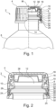
1 ist eine Darstellung eines oberen Abschnittes eines erfindungsgemäßen medizinischen Fluidbehälters, welcher mit einem Schraubdeckel verschlossen ist.1 Fig. 12 is an illustration of a top portion of a medical fluid container of the present invention sealed with a screw cap. -
2 ist eine vergrößerte Schnittdarstellung des oberen Abschnitts des erfindungsgemäßen medizinischen Fluidbehälters, welcher mit einem Schraubdeckel verschlossen ist.2 Fig. 12 is an enlarged sectional view of the upper portion of the medical fluid container of the present invention which is closed with a screw cap. -
3 ist eine vergrößerte Schnittdarstellung des oberen Abschnitts des erfindungsgemäßen medizinischen Fluidbehälters.3 12 is an enlarged sectional view of the upper portion of the medical fluid container of the present invention. -
4 ist eine vergrößerte Schnittdarstellung des oberen Abschnitts des erfindungsgemäßen medizinischen Fluidbehälters mit einer Blasdornspitze und einer Matrize.4 12 is an enlarged sectional view of the top portion of the medical fluid container of the present invention with a blow mandrel tip and a die.
Detaillierte BeschreibungDetailed description
Nachstehend werden Ausführungsbeispiele der vorliegenden Offenbarung auf der Basis der zugehörigen Figuren beschrieben.Embodiments of the present disclosure will be described below based on the accompanying figures.
Die Ausgestaltung des Behälterkörpers 8 ist für die vorliegende Offenbarung von nachrangiger Bedeutung, weshalb auf eine detaillierte Darstellung und ausführliche Beschreibung des Behälterkörpers 8 verzichtet wird. Der Behälterkörper 8 kann jegliche geometrische Form aufweisen, welche für eine Verwendung als medizinischer Fluidbehälter 2 dienlich ist.The configuration of the
Der Behälter-Anschlussstutzen 6 wird nachfolgend ausführlich anhand von
Die Wandstärke p des Behälter-Anschlussstutzen 6 beträgt an keiner Stelle mehr als 1,8 mm. Der Durchmesser d1 beträgt ungefähr 28 mm und der Durchmesser d2 beträgt ungefähr 25 mm. Der Winkel α beträgt ungefähr 30°.The wall thickness p of the
Der Schraubdeckel beinhaltet weiterhin ein Dichtungseinlage 38, welches jedoch im Rahmen dieser Offenbarung nicht näher betrachtet wird.The screw cap also includes a sealing
Ein Blasdorn mit der Blasdornspitze 40 wird in einen im Wesentlichen zylindrischen Behälter-Rohling, vorzugweisen in Form eines Schlauchs eingeführt. Der Behälter-Rohling besteht hierbei vorzugsweise aus einem Thermoplast. Der Behälter-Rohling wird erwärmt und mittels des Blasdorns mit der Blasdornspitze 40 in die Matrize 42 eingeführt. Die Blasdornspitze 40 presst den Behälter-Rohling gegen die Matrize 42, insbesondere gegen eine matrizenseitige Staukante 44. Hierdurch wird der Behälter-Anschlussstutzen 6, welcher in
BezugszeichenlisteReference List
- 22
- medizinischer Fluidbehältermedical fluid container
- 44
- Schraubdeckelscrew cap
- 66
- Behälter-Anschlussstutzencontainer connection piece
- 88th
- Behälterkörpercontainer body
- 1010
- Außengewindeexternal thread
- 1212
- Innenkanalinner canal
- 1414
- Behälterinnenraumcontainer interior
- 1616
- erste zylindrische Kanalformfirst cylindrical canal shape
- 1818
- Ausgussöffnung / freie MündungPouring opening / free mouth
- 2020
- konischer Bereichconical area
- 2222
- zweite zylindrische Kanalformsecond cylindrical channel shape
- 2424
- Wulstgeometriebead geometry
- 2626
- Radiusradius
- 2828
- Originalitätsringoriginality ring
- 3030
- Oberringtop ring
- 3232
- Unterringunderring
- 3434
- Sollbruchstegpredetermined breaking point
- 3636
- Rückhaltegeometrieretention geometry
- 3838
- Dichtungseinlagegasket insert
- 4040
- Blasdornspitzeblow pin tip
- 4242
- Matrizedie
- 4444
- matrizenseitige Staukantedie-side accumulation edge
- 4646
- Druckgasleitungcompressed gas line
- αa
- Winkelangle
- MM
- Mittelachsecentral axis
- d1d1
- Durchmesser 1diameter 1
- d2d2
-
Durchmesser 2
diameter 2 - pp
- WandstärkeWall thickness
Claims (11)
Priority Applications (4)
| Application Number | Priority Date | Filing Date | Title |
|---|---|---|---|
| DE102021125561.9A DE102021125561A1 (en) | 2021-10-01 | 2021-10-01 | Medical Fluid Container |
| US18/697,456 US12564542B2 (en) | 2021-10-01 | 2022-09-21 | Medical fluid container |
| EP22793139.1A EP4408639A2 (en) | 2021-10-01 | 2022-09-21 | Medical fluid container |
| PCT/EP2022/076234 WO2023052218A2 (en) | 2021-10-01 | 2022-09-21 | Medical fluid container |
Applications Claiming Priority (1)
| Application Number | Priority Date | Filing Date | Title |
|---|---|---|---|
| DE102021125561.9A DE102021125561A1 (en) | 2021-10-01 | 2021-10-01 | Medical Fluid Container |
Publications (1)
| Publication Number | Publication Date |
|---|---|
| DE102021125561A1 true DE102021125561A1 (en) | 2023-04-06 |
Family
ID=83903190
Family Applications (1)
| Application Number | Title | Priority Date | Filing Date |
|---|---|---|---|
| DE102021125561.9A Pending DE102021125561A1 (en) | 2021-10-01 | 2021-10-01 | Medical Fluid Container |
Country Status (4)
| Country | Link |
|---|---|
| US (1) | US12564542B2 (en) |
| EP (1) | EP4408639A2 (en) |
| DE (1) | DE102021125561A1 (en) |
| WO (1) | WO2023052218A2 (en) |
Citations (6)
| Publication number | Priority date | Publication date | Assignee | Title |
|---|---|---|---|---|
| JPH0457732A (en) | 1990-06-25 | 1992-02-25 | Dainippon Printing Co Ltd | Biaxially stretched blow molding-fabricated container having heat resistance and gas-barrier property |
| US20050271843A1 (en) | 1992-07-07 | 2005-12-08 | Collette Wayne N | Method of forming container with high-crystallinity sidewall and low-crystallinity base |
| DE202007009983U1 (en) | 2007-07-17 | 2007-10-31 | Krones Ag | Plastic container with engagement groove |
| WO2007122324A1 (en) | 2006-04-20 | 2007-11-01 | Tetra Laval Holdings & Finance S.A. | Container comprising a neck equipped with a screwed closure |
| WO2009053921A1 (en) | 2007-10-23 | 2009-04-30 | S.I.P.A. Societa' Industrializzazione Progettazione E Automazione S.P.A. | Plastic material container |
| US20120027966A1 (en) | 2008-12-30 | 2012-02-02 | Moreno Barel | Process for Drawing, Injection and Blowing Ultra-Light Weight Bottles ( Swerve Neck) |
Family Cites Families (9)
| Publication number | Priority date | Publication date | Assignee | Title |
|---|---|---|---|---|
| US3224038A (en) * | 1962-03-28 | 1965-12-21 | Schmalbach Ag J A | Apparatus for the manufacture of blown, hollow articles |
| US4007243A (en) | 1974-02-25 | 1977-02-08 | Hoover Ball And Bearing Company | Method of blow molding |
| US4065535A (en) | 1976-12-27 | 1977-12-27 | Hercules Incorporated | Thread forming and neck finishing process |
| JP5918888B1 (en) | 2015-08-28 | 2016-05-18 | エム・エフ・ヴィ株式会社 | Refill bottle |
| DE102017009012A1 (en) | 2017-09-26 | 2019-03-28 | Kocher-Plastik Maschinenbau Gmbh | Container and connecting and manufacturing device |
| US20240270433A1 (en) * | 2021-06-08 | 2024-08-15 | PAPACKS SALES GmbH | Molded product with connection element |
| JP2024527906A (en) * | 2021-07-27 | 2024-07-26 | コーニング インコーポレイテッド | Pharmaceutical container with a neck having a non-uniform outer surface and method for evaluating the same |
| JP7651172B2 (en) * | 2021-08-06 | 2025-03-26 | 大成化工株式会社 | Chemical liquid applicator and chemical liquid application container equipped with same |
| EP4190303A1 (en) * | 2021-12-01 | 2023-06-07 | Wirthwein Medical GmbH & Co. KG | Medication container |
-
2021
- 2021-10-01 DE DE102021125561.9A patent/DE102021125561A1/en active Pending
-
2022
- 2022-09-21 EP EP22793139.1A patent/EP4408639A2/en active Pending
- 2022-09-21 US US18/697,456 patent/US12564542B2/en active Active
- 2022-09-21 WO PCT/EP2022/076234 patent/WO2023052218A2/en not_active Ceased
Patent Citations (6)
| Publication number | Priority date | Publication date | Assignee | Title |
|---|---|---|---|---|
| JPH0457732A (en) | 1990-06-25 | 1992-02-25 | Dainippon Printing Co Ltd | Biaxially stretched blow molding-fabricated container having heat resistance and gas-barrier property |
| US20050271843A1 (en) | 1992-07-07 | 2005-12-08 | Collette Wayne N | Method of forming container with high-crystallinity sidewall and low-crystallinity base |
| WO2007122324A1 (en) | 2006-04-20 | 2007-11-01 | Tetra Laval Holdings & Finance S.A. | Container comprising a neck equipped with a screwed closure |
| DE202007009983U1 (en) | 2007-07-17 | 2007-10-31 | Krones Ag | Plastic container with engagement groove |
| WO2009053921A1 (en) | 2007-10-23 | 2009-04-30 | S.I.P.A. Societa' Industrializzazione Progettazione E Automazione S.P.A. | Plastic material container |
| US20120027966A1 (en) | 2008-12-30 | 2012-02-02 | Moreno Barel | Process for Drawing, Injection and Blowing Ultra-Light Weight Bottles ( Swerve Neck) |
Also Published As
| Publication number | Publication date |
|---|---|
| WO2023052218A3 (en) | 2023-05-25 |
| WO2023052218A2 (en) | 2023-04-06 |
| EP4408639A2 (en) | 2024-08-07 |
| US12564542B2 (en) | 2026-03-03 |
| US20240398664A1 (en) | 2024-12-05 |
Similar Documents
| Publication | Publication Date | Title |
|---|---|---|
| DE10215722B4 (en) | Method and device for processing preforms | |
| EP3433120B1 (en) | Operating liquid container with stiffening element and method for manufacturing an operating liquid container | |
| DE112014003365T5 (en) | Method for attaching an accessory to the wall of a container | |
| DE19944579B4 (en) | Process for producing a plastic container | |
| DE69528038T2 (en) | BIAXIAL-ORIENTED BLOW MOLDING PROCESS AND PREFORM HOLDING DEVICE | |
| DE102015112223A1 (en) | Injection mold with core ring | |
| DE69501713T2 (en) | Process for the manufacture of containers for liquid dispensing | |
| EP1045179B1 (en) | Sealing device | |
| DE4412907C1 (en) | Plastics delivery tube | |
| DE102021125561A1 (en) | Medical Fluid Container | |
| DE2557416A1 (en) | METHOD AND APPARATUS FOR MANUFACTURING A PIPE CONNECTOR WITH RADIAL EXPANSION | |
| EP3911490B1 (en) | Method and device for producing a fluid line with connecting element | |
| DE4205332A1 (en) | CONNECTING A METAL CONNECTING ELEMENT WITH A BLOW-MOLDED PLASTIC CONTAINER | |
| DE102017215191A1 (en) | Pressure vessel for storing liquid and / or gaseous media | |
| DE69410717T2 (en) | Method and device for the production of tubular articles with a surrounding accumulation of material | |
| AT403676B (en) | HOLLOW MOLD FOR THE PRODUCTION OF HOLLOW BODIES WITH HANDLE TIPS FROM THERMOPLASTIC MATERIAL | |
| DE19730800C2 (en) | Method of making a hot water bottle and hot water bottle made thereafter | |
| EP4495019A1 (en) | Extrusion blow-molded container | |
| EP4069492B1 (en) | Blow mold, stretch blow molder and method for forming a container | |
| EP4159638B1 (en) | Fluid container with closure cap | |
| DE102021104435A1 (en) | Vertically split feeder for use in casting metals in molds and method of making same | |
| EP3957462A1 (en) | Method of manufacturing a half-shell | |
| DE3940497C2 (en) | ||
| DE4412657A1 (en) | Plastic container for fluids and mfg. process | |
| DE102018204145A1 (en) | Method and tool for producing a plastic container, in particular a fuel tank, by internal pressure forming |
Legal Events
| Date | Code | Title | Description |
|---|---|---|---|
| R079 | Amendment of ipc main class |
Free format text: PREVIOUS MAIN CLASS: B65D0051000000 Ipc: B65D0001020000 |
|
| R163 | Identified publications notified |