DE102021125212A1 - Lamination stack for an electrical machine and method for producing a lamination stack - Google Patents
Lamination stack for an electrical machine and method for producing a lamination stack Download PDFInfo
- Publication number
- DE102021125212A1 DE102021125212A1 DE102021125212.1A DE102021125212A DE102021125212A1 DE 102021125212 A1 DE102021125212 A1 DE 102021125212A1 DE 102021125212 A DE102021125212 A DE 102021125212A DE 102021125212 A1 DE102021125212 A1 DE 102021125212A1
- Authority
- DE
- Germany
- Prior art keywords
- laminated core
- electrical
- individual
- casting element
- openings
- Prior art date
- Legal status (The legal status is an assumption and is not a legal conclusion. Google has not performed a legal analysis and makes no representation as to the accuracy of the status listed.)
- Granted
Links
- 238000003475 lamination Methods 0.000 title claims abstract description 21
- 238000004519 manufacturing process Methods 0.000 title claims description 16
- 238000005266 casting Methods 0.000 claims abstract description 41
- 238000001721 transfer moulding Methods 0.000 claims description 22
- 239000000463 material Substances 0.000 claims description 15
- 238000000034 method Methods 0.000 claims description 8
- 239000002184 metal Substances 0.000 claims description 6
- 229910052751 metal Inorganic materials 0.000 claims description 6
- 230000000149 penetrating effect Effects 0.000 claims 1
- 238000001746 injection moulding Methods 0.000 description 6
- 239000004020 conductor Substances 0.000 description 4
- 239000004033 plastic Substances 0.000 description 4
- 239000003822 epoxy resin Substances 0.000 description 3
- 238000009413 insulation Methods 0.000 description 3
- 229920000647 polyepoxide Polymers 0.000 description 3
- 238000004804 winding Methods 0.000 description 3
- 238000004026 adhesive bonding Methods 0.000 description 2
- 238000000576 coating method Methods 0.000 description 2
- 150000001875 compounds Chemical class 0.000 description 2
- 239000006249 magnetic particle Substances 0.000 description 2
- 239000011159 matrix material Substances 0.000 description 2
- 238000004382 potting Methods 0.000 description 2
- 238000004080 punching Methods 0.000 description 2
- 239000012815 thermoplastic material Substances 0.000 description 2
- 238000003466 welding Methods 0.000 description 2
- BUHVIAUBTBOHAG-FOYDDCNASA-N (2r,3r,4s,5r)-2-[6-[[2-(3,5-dimethoxyphenyl)-2-(2-methylphenyl)ethyl]amino]purin-9-yl]-5-(hydroxymethyl)oxolane-3,4-diol Chemical compound COC1=CC(OC)=CC(C(CNC=2C=3N=CN(C=3N=CN=2)[C@H]2[C@@H]([C@H](O)[C@@H](CO)O2)O)C=2C(=CC=CC=2)C)=C1 BUHVIAUBTBOHAG-FOYDDCNASA-N 0.000 description 1
- RYGMFSIKBFXOCR-UHFFFAOYSA-N Copper Chemical compound [Cu] RYGMFSIKBFXOCR-UHFFFAOYSA-N 0.000 description 1
- 241000736305 Marsilea quadrifolia Species 0.000 description 1
- 241000555745 Sciuridae Species 0.000 description 1
- 230000006978 adaptation Effects 0.000 description 1
- 230000004888 barrier function Effects 0.000 description 1
- 239000007795 chemical reaction product Substances 0.000 description 1
- 239000011248 coating agent Substances 0.000 description 1
- 238000000748 compression moulding Methods 0.000 description 1
- 229910052802 copper Inorganic materials 0.000 description 1
- 239000010949 copper Substances 0.000 description 1
- 230000001066 destructive effect Effects 0.000 description 1
- 230000000694 effects Effects 0.000 description 1
- 238000010292 electrical insulation Methods 0.000 description 1
- 238000005538 encapsulation Methods 0.000 description 1
- 239000000835 fiber Substances 0.000 description 1
- 238000007667 floating Methods 0.000 description 1
- 230000004907 flux Effects 0.000 description 1
- 238000003780 insertion Methods 0.000 description 1
- 230000037431 insertion Effects 0.000 description 1
- 239000000203 mixture Substances 0.000 description 1
- 238000000465 moulding Methods 0.000 description 1
- 238000003825 pressing Methods 0.000 description 1
- 239000000047 product Substances 0.000 description 1
- 238000007789 sealing Methods 0.000 description 1
- 239000011265 semifinished product Substances 0.000 description 1
- 239000000243 solution Substances 0.000 description 1
- 238000005507 spraying Methods 0.000 description 1
- 230000001360 synchronised effect Effects 0.000 description 1
- 229920001187 thermosetting polymer Polymers 0.000 description 1
- 238000009423 ventilation Methods 0.000 description 1
Images



Classifications
-
- H—ELECTRICITY
- H02—GENERATION; CONVERSION OR DISTRIBUTION OF ELECTRIC POWER
- H02K—DYNAMO-ELECTRIC MACHINES
- H02K1/00—Details of the magnetic circuit
- H02K1/04—Details of the magnetic circuit characterised by the material used for insulating the magnetic circuit or parts thereof
-
- H—ELECTRICITY
- H02—GENERATION; CONVERSION OR DISTRIBUTION OF ELECTRIC POWER
- H02K—DYNAMO-ELECTRIC MACHINES
- H02K1/00—Details of the magnetic circuit
- H02K1/06—Details of the magnetic circuit characterised by the shape, form or construction
- H02K1/12—Stationary parts of the magnetic circuit
- H02K1/16—Stator cores with slots for windings
-
- H—ELECTRICITY
- H02—GENERATION; CONVERSION OR DISTRIBUTION OF ELECTRIC POWER
- H02K—DYNAMO-ELECTRIC MACHINES
- H02K1/00—Details of the magnetic circuit
- H02K1/06—Details of the magnetic circuit characterised by the shape, form or construction
- H02K1/22—Rotating parts of the magnetic circuit
- H02K1/27—Rotor cores with permanent magnets
- H02K1/2706—Inner rotors
- H02K1/272—Inner rotors the magnetisation axis of the magnets being perpendicular to the rotor axis
- H02K1/274—Inner rotors the magnetisation axis of the magnets being perpendicular to the rotor axis the rotor consisting of two or more circumferentially positioned magnets
- H02K1/2753—Inner rotors the magnetisation axis of the magnets being perpendicular to the rotor axis the rotor consisting of two or more circumferentially positioned magnets the rotor consisting of magnets or groups of magnets arranged with alternating polarity
- H02K1/276—Magnets embedded in the magnetic core, e.g. interior permanent magnets [IPM]
- H02K1/2766—Magnets embedded in the magnetic core, e.g. interior permanent magnets [IPM] having a flux concentration effect
-
- H—ELECTRICITY
- H02—GENERATION; CONVERSION OR DISTRIBUTION OF ELECTRIC POWER
- H02K—DYNAMO-ELECTRIC MACHINES
- H02K15/00—Processes or apparatus specially adapted for manufacturing, assembling, maintaining or repairing of dynamo-electric machines
- H02K15/02—Processes or apparatus specially adapted for manufacturing, assembling, maintaining or repairing of dynamo-electric machines of stator or rotor bodies
- H02K15/021—Magnetic cores
-
- H—ELECTRICITY
- H02—GENERATION; CONVERSION OR DISTRIBUTION OF ELECTRIC POWER
- H02K—DYNAMO-ELECTRIC MACHINES
- H02K15/00—Processes or apparatus specially adapted for manufacturing, assembling, maintaining or repairing of dynamo-electric machines
- H02K15/02—Processes or apparatus specially adapted for manufacturing, assembling, maintaining or repairing of dynamo-electric machines of stator or rotor bodies
- H02K15/03—Processes or apparatus specially adapted for manufacturing, assembling, maintaining or repairing of dynamo-electric machines of stator or rotor bodies having permanent magnets
-
- H—ELECTRICITY
- H02—GENERATION; CONVERSION OR DISTRIBUTION OF ELECTRIC POWER
- H02K—DYNAMO-ELECTRIC MACHINES
- H02K15/00—Processes or apparatus specially adapted for manufacturing, assembling, maintaining or repairing of dynamo-electric machines
- H02K15/12—Impregnating, moulding insulation, heating or drying of windings, stators, rotors or machines
Landscapes
- Engineering & Computer Science (AREA)
- Power Engineering (AREA)
- Manufacturing & Machinery (AREA)
- Manufacture Of Motors, Generators (AREA)
- Iron Core Of Rotating Electric Machines (AREA)
Abstract
Ein Elektroblechpaket (2) für eine elektrische Maschine umfasst eine Anzahl Einzelbleche (3), welche elektrisch voneinander isoliert gestapelt sind und miteinander fluchtende Durchbrüche (4, 8) aufweisen, sowie ein die Durchbrüche (4, 8) durchdringendes und hierbei die Einzelbleche (3) formschlüssig hintergreifendes duroplastisches Vergusselement (5).

Description
Die Erfindung betrifft ein Elektroblechpaket für einen Stator oder Rotor einer elektrischen Maschine. Ferner betrifft die Erfindung ein Verfahren zur Herstellung eines Elektroblechpaketes, welches zur Verwendung in einer elektrischen Maschine geeignet ist.The invention relates to an electrical laminated core for a stator or rotor of an electrical machine. Furthermore, the invention relates to a method for producing an electrical laminated core which is suitable for use in an electrical machine.
Die
Im Unterschied zum Spritzgießen, bei welchem thermoplastisches Material verarbeitet wird, wird beim Spritzpressen duroplastisches Material verarbeitet. Dies kann geschehen, indem mit Hilfe eines Kolbens Formmasse von einer beheizten Vorkammer aus in einen Hohlraum eingebracht wird und dort aushärtet. Grundsätzlich bekannt ist auch die Herstellung faserverstärkter Werkstücke durch Spritzpressen.In contrast to injection molding, in which thermoplastic material is processed, duroplastic material is processed in transfer molding. This can be done by using a piston to introduce molding compound from a heated antechamber into a cavity and hardens there. Also known in principle is the production of fiber-reinforced workpieces by transfer molding.
Die Umspritzung eines Stators einer elektrischen Maschine mit einer duroplastischen Masse ist beispielsweise in der
Die
Aus der
Die
Die
Aus der
Der Erfindung liegt die Aufgabe zugrunde, Komponenten elektrischer Maschinen, das heißt Elektromotoren, Generatoren oder Transformatoren, bei deren Herstellung Spritzpressen zum Einsatz kommt, gegenüber dem genannten Stand der Technik insbesondere unter fertigungstechnischen Aspekten weiterzuentwickeln.The invention is based on the object of further developing components of electrical machines, ie electric motors, generators or transformers, in the manufacture of which transfer molding is used, compared to the prior art mentioned, in particular with regard to manufacturing aspects.
Diese Aufgabe wird erfindungsgemäß gelöst durch ein Elektroblechpaket mit den Merkmalen des Anspruchs 1. Ebenso wird die Aufgabe gelöst durch ein Verfahren zur Herstellung eines für die Verwendung in einer elektrischen Maschine geeigneten Elektroblechpakets gemäß Anspruch 9. Im Folgenden im Zusammenhang mit dem Herstellungsverfahren erläuterte Ausgestaltungen und Vorteile der Erfindung gelten sinngemäß auch für die Vorrichtung, das heißt das für Verwendung in einer elektrischen Maschine vorgesehene Elektroblechpaket, und umgekehrt.This object is achieved according to the invention by an electrical laminated core having the features of
Das Elektroblechpaket umfasst eine Anzahl an Einzelblechen, welche elektrisch voneinander isoliert gestapelt sind und miteinander fluchtende Durchbrüche aufweisen. Ferner ist ein duroplastisches, durch Spritzpressen erzeugtes Vergusselement vorgesehen, welches die Gesamtheit der Durchbrüche durchdringt und hierbei die Einzelbleche formschlüssig hintergreift.The stack of electrical laminations comprises a number of individual laminations which are stacked in an electrically isolated manner from one another and have openings which are aligned with one another. Furthermore, a duroplastic casting element produced by injection molding is provided, which penetrates the entirety of the openings and thereby engages behind the individual sheets in a form-fitting manner.
Das duroplastische Material, welches durch Transfer Moulding verarbeitet wird, weist elektrisch isolierende Eigenschaften auf. Damit sind insbesondere elektrische Überschläge zwischen elektrischen Leitungen und Blechen des Elektroblechpakets ausgeschlossen. Zugleich kann die Materialzusammensetzung derart gewählt werden, dass eine für den Anwendungsfall ausreichend hohe thermische Leitfähigkeit gegeben ist. Insbesondere ist als duroplastisches Material Epoxidharz verwendbar, welches zum Beispiel unter der Bezeichnung EPOXIDUR® EP 3161 E am Markt erhältlich ist.The duroplastic material, which is processed by transfer molding, has electrically insulating properties. In this way, in particular, electrical flashovers between electrical lines and laminations of the electrical laminated core are ruled out. At the same time, the material composition can be chosen such that one for the Application is given sufficiently high thermal conductivity. In particular, epoxy resin can be used as the duroplastic material, which is available on the market, for example, under the name EPOXIDUR® EP 3161 E.
Um den erforderlichen Formschluss zu den metallischen Komponenten des Blechpakets herzustellen, weist das insgesamt längliche Vergusselement eine über seine Länge uneinheitliche Breite auf. Beispielsweise weist das Vergusselement eine jeweils zwischen zwei Einzelblechen gegebene Maximalbreite auf, die mindestens das 1,5-fache der in den Durchbrüchen zu messenden Minimalbreite des Vergusselementes beträgt. Die Maximalbreite beträgt hierbei insbesondere nicht mehr als das Dreifache der Minimalbreite des Vergusselementes.In order to produce the required form fit with the metallic components of the laminated core, the casting element, which is elongated overall, has a non-uniform width over its length. For example, the casting element has a maximum width between two individual sheets, which is at least 1.5 times the minimum width of the casting element to be measured in the openings. In this case, the maximum width is in particular no more than three times the minimum width of the casting element.
Gemäß verschiedener möglicher Ausführungsformen sind die Einzelbleche frei von direkt zwischen diesen Einzelblechen gebildetem Formschluss aufeinandergestapelt. Dies hat den Vorteil, dass jegliche Verfahrensschritte, in denen die Einzelbleche umgeformt werden, etwa durch Clinchen, entfallen können. Ebenso können Schritte wie Laserschweißen entfallen. Das mindestens eine Vergusselement, welche durch Transfer Moulding erzeugt wird, kann das einzige Mittel zum Zusammenhalten des gesamten Elektroblechpakets darstellen.According to various possible embodiments, the individual sheets are stacked one on top of the other without any positive locking formed directly between these individual sheets. This has the advantage that any process steps in which the individual sheets are formed, such as by clinching, can be omitted. Steps such as laser welding can also be omitted. The at least one casting element, which is produced by transfer molding, can represent the only means for holding the entire laminated core together.
Was die Form der Durchbrüche des Blechstapels betrifft, sind verschiedenste Varianten möglich. Weisen die Durchbrüche eine geschlossene Umrandung auf, kann es sich insbesondere um kreisrunde, ovale oder polygonförmige Löcher handeln. Ebenso können die Durchbrüche beispielsweise eine Kleeblatt-, Standuhr- oder Schwalbenschwanzform haben. In allen Fällen sind durch das Aushärten des duroplastischen Materials Verspannungen innerhalb des Elektroblechpakets erzeugbar, wobei das Vergusselement insbesondere zur Übertragung von Zugkräften geeignet ist und damit einen Zuganker darstellen kann. Der vielfach gegebene Formschluss zwischen dem Vergusselement und den einzelnen Blechen des Elektroblechpaketes kann hierbei dafür sorgen, dass Kräfte nicht über die gesamte Länge des Vergusselementes, sondern nur über einen Bruchteil seiner Länge zu übertragen sind. Insgesamt sind somit in Relation zu den Abmessungen des Vergusselementes hohe Kräfte innerhalb des Elektroblechpaketes übertragbar.As far as the shape of the openings in the sheet metal stack is concerned, a wide variety of variants are possible. If the openings have a closed border, they can in particular be circular, oval or polygonal holes. Likewise, the openings can have, for example, a cloverleaf, grandfather clock or dovetail shape. In all cases, as a result of the curing of the duroplastic material, tension can be generated within the laminated core stack of electrical conductors, with the casting element being particularly suitable for transmitting tensile forces and thus being able to represent a tie rod. The often given positive connection between the casting element and the individual laminations of the electrical laminated core can ensure that forces are not to be transmitted over the entire length of the casting element, but only over a fraction of its length. Overall, in relation to the dimensions of the casting element, high forces can therefore be transmitted within the laminated core stack.
Im Fall von Durchbrüchen ohne geschlossene Umrandung bilden diese insbesondere eine Nut, beispielsweise eine U-förmige Nut eines Stators. In die Statornut können elektrische Leiter eingebracht werden. Auch ist es möglich, Leiter innerhalb der Statornut unmittelbar durch duroplastisches Material zu umspritzen. Im Fall des Einbringens von Kupferwicklungen im Hairpin-Verfahren ist ein direkter Verschluss einer Nut durch das Transfer Moulding möglich, so dass das Einbringen eines Verschlusskeils entfallen kann.In the case of openings without a closed border, these form in particular a groove, for example a U-shaped groove of a stator. Electrical conductors can be inserted into the stator slot. It is also possible to encapsulate conductors directly within the stator slot with duroplastic material. If copper windings are inserted using the hairpin method, a slot can be closed directly by transfer molding, so that there is no need to insert a sealing wedge.
Allgemein ist das Elektroblechpaket herstellbar, indem ein Stapel elektrisch gegeneinander isolierter Einzelbleche, welche miteinander fluchtende Durchbrüche aufweisen, durch Transfer Moulding mit einem insgesamt bolzenförmigen duroplastischen, in die Durchbrüche eingebrachten Vergusselement, welches zur Aufnahme von Zugkräften zwischen beliebigen der Einzelbleche ausgebildet ist, versehen wird. Beim Transfer Moulding, das heißt Spritzgießen, wird duroplastisches Material insbesondere derart zwischen die Einzelbleiche eingebracht, dass ein Formschluss zwischen jedem der Einzelbleche und dem Vergusselement entsteht.In general, the stack of electrical laminations can be produced by providing a stack of individual laminations that are electrically insulated from one another and have openings that are aligned with one another, using transfer molding with a generally bolt-shaped duroplastic casting element that is introduced into the openings and is designed to absorb tensile forces between any of the individual laminations. In the case of transfer molding, that is to say injection molding, duroplastic material is introduced between the individual sheets in particular in such a way that a form fit is created between each of the individual sheets and the casting element.
Handelt es sich bei dem Elektroblechpaket um ein Teil eines mit Permanentmagneten zu bestückenden Rotors eines Elektromotors, so kann die Fixierung der einzelnen Magnete in einem einzigen Arbeitsgang zusammen mit der Herstellung der Verbindung zwischen den Einzelblechen durch Transfer Moulding erfolgen. Als Werkstoff hierfür ist insbesondere Epoxidharz geeignet. Im Vergleich zu herkömmlichen Herstellungsverfahren ist damit die Anzahl der Arbeitsschritte und der Abstimmaufwand reduziert, wobei zugleich eine hohe geometrische Präzision des Endproduktes, das heißt Elektroblechpaketes einschließlich der Permanentmagnete, erzielbar ist.If the laminated core is part of an electric motor rotor to be fitted with permanent magnets, the individual magnets can be fixed in a single operation together with the production of the connection between the individual laminations by transfer molding. Epoxy resin is particularly suitable as the material for this. Compared to conventional manufacturing methods, the number of work steps and the tuning effort are reduced, while at the same time a high geometric precision of the end product, ie the laminated core including the permanent magnets, can be achieved.
Der Vorgang des Transfer Mouldings ist mit einer magnetischen Fixierung des Blechpakets kombinierbar. Dies gilt insbesondere für Verfahrensvarianten, in denen durch Transfer Moulding eine Statornut isoliert wird. Unabhängig von der Art des Blechpaketes können die Einzelbleche mit Hilfe eines Spanndorns zentriert werden, welcher auch für die geforderte Rechtwinkligkeit innerhalb der zu montierenden Anordnung sorgt. Gleichzeitig kann das Blechpaket durch Zusammenpressen eines für das Transfer Moulding vorgesehenen Werkzeugs hinsichtlich seiner Abmessung in axialer Richtung, das heißt der Richtung normal zu den Ebenen, in welchen die Einzelbleche angeordnet sind, justiert werden.The process of transfer molding can be combined with a magnetic fixation of the laminated core. This applies in particular to process variants in which a stator slot is insulated by transfer molding. Regardless of the type of laminated core, the individual sheets can be centered using a mandrel, which also ensures the required squareness within the assembly to be assembled. At the same time, the laminated core can be adjusted in terms of its dimensions in the axial direction, ie the direction normal to the planes in which the individual sheets are arranged, by pressing together a tool provided for the transfer molding.
Der Vorteil der Erfindung liegt insbesondere darin, dass bei der Herstellung von Statoren oder Rotoren von Elektromotoren oder Generatoren aufwendige Herstellungsschritte wie Kleben oder Umformen komplett entfallen oder im Vergleich zu herkömmlichen Lösungen zumindest deutlich einfacher gestaltet werden können. Funktionale Einschränkungen des hergestellten Bauteils, das heißt Stators oder Rotors, sind hierbei nicht in Kauf zu nehmen. Vielmehr zeichnet sich das Herstellungsverfahren durch eine Anwendbarkeit bei einer Vielzahl unterschiedlichster elektrotechnischer Produkte, deren Komponenten durch betriebsbedingte Kräfte belastet sind, aus. Eine zerstörungsfreie Demontage des Elektroblechpakets, welches durch das duroplastische Vergusselement oder eine Mehrzahl solcher Vergusselemente zusammengehalten wird, ist in der Regel nicht vorgesehen. Das Elektroblechpaket ist unter Verwendung standardisierter Elektrobleche ohne Beschichtung herstellbar.The particular advantage of the invention is that in the production of stators or rotors of electric motors or generators, complex production steps such as gluing or forming are completely eliminated or can at least be made much simpler compared to conventional solutions. Functional limitations of the manufactured component, i.e. stator or rotor, are not to be accepted here men. Rather, the manufacturing process is characterized by its applicability to a large number of different electrotechnical products whose components are subject to operational forces. A non-destructive dismantling of the laminated core stack, which is held together by the duroplastic casting element or a plurality of such casting elements, is generally not provided. The electrical sheet stack can be produced using standardized electrical sheets without a coating.
Nachfolgend werden mehrere Ausführungsbeispiele der Erfindung anhand einer Zeichnung näher erläutert. Hierin zeigen:
-
1 den Aufbau eines Elektroblechpakets für eine elektrische Maschine in einer schematischen Schnittdarstellung, -
2 ein Elektroblechpaket eines Stators eines Elektromotors in perspektivischer Ansicht, -
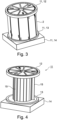
3 eine Anordnung zum Verbinden der Einzelbleche des Elektroblechpakets nach2 mittels Transfer Moulding, -
4 dieAnordnung nach 3 ohne Elektroblechpaket, -
5 ein Detail eines Elektroblechpakets eines Rotors eines Elektromotors, -
6 den Querschnitt eines Vergusselementes der Anordnung nach1 , -
7 ein weiteres Vergusselement für ein Elektroblechpaket inAnsicht analog 6 , -
8 ausschnittsweise einen ein Elektroblechpaket umfassenden Rotor eines Elektromotors in Draufsicht, -
9 dieAnordnung nach 8 in perspektivischer Ansicht.
-
1 the structure of an electrical laminated core for an electrical machine in a schematic sectional view, -
2 a perspective view of an electrical laminated core of a stator of an electric motor, -
3 according to an arrangement for connecting the individual laminations of the electricallaminated core 2 by transfer moulding, -
4 according to thearrangement 3 without electrical laminated core, -
5 a detail of an electrical laminated core of a rotor of an electric motor, -
6 the cross section of a casting element according to thearrangement 1 , -
7 Another casting element for an electrical laminated core in asimilar view 6 , -
8th detail of a rotor of an electric motor comprising an electrical laminated core in plan view, -
9 according to the arrangement8th in perspective view.
Die folgenden Erläuterungen beziehen sich, soweit nicht anders angegeben, auf sämtliche Ausführungsbeispiele. Einander entsprechende oder prinzipiell gleichwirkende Teile sind in allen Figuren mit den gleichen Bezugszeichen gekennzeichnet.Unless otherwise stated, the following explanations relate to all exemplary embodiments. Parts that correspond to one another or have the same effect in principle are marked with the same reference symbols in all figures.
Ein insgesamt mit dem Bezugszeichen 1 gekennzeichnetes Funktionsteil eines Elektromotors, das heißt ein Stator oder ein Rotor, umfasst ein Elektroblechpaket 2, welches aus einer Vielzahl an Einzelblechen 3 aufgebaut ist. Zwischen den Einzelblechen 3 befinden sich elektrisch isolierende Lagen, die entweder durch gesonderte Komponenten oder durch Beschichtungen der Einzelbleche 3 bereitgestellt werden können. Ebenso ist es möglich, die elektrische Isolation innerhalb des Elektroblechpakets 2 ausschließlich durch das Verfahren des Transfer Mouldings, auf welches noch im Detail eingegangen werden wird, herzustellen.A functional part of an electric motor, identified overall by the
In allen Fällen weisen die aufeinander gestapelten Einzelbleche 3, das heißt die einzelnen Elektrobleche, mehrere Durchbrüche 4 mit geschlossener Umrandung, insbesondere kreisrunde Löcher, und/oder Nuten 8, welche allgemein als Durchbrüche ohne geschlossene Umrandung bezeichnet werden, auf. Die Durchbrüche 4, 8 sind beispielsweise durch Stanzen herstellbar. Zumindest einzelne Durchbrüche 4, 8 sind vollständig oder teilweise durch ein Vergusselement 5 aus duroplastischem Material ausgefüllt. Die Vergusselemente 5 sind elektrisch isolierend und stellen formschlüssige, mechanisch belastbare Verbindungen zwischen den Einzelblechen 3 her.In all cases, the stacked
Jedes Vergusselement 5 erstreckt sich parallel zur Mittelachse des Funktionsteils 1 und umfasst alternierend angeordnete sogenannte eingeschnürte Abschnitte 6 und Formschlussabschlüsse 7. Die Breite der eingeschnürten Abschnitte 6 ist mit Bmin, die Breite der Formschlussabschnitte 7 mit Bmax angegeben. In axialer Richtung des Funktionsteils 1 und damit auch des Vergusselementes 5 weist jeder eingeschnürte Abschnitt 6 eine Dicke DE auf, welche der Dicke eines Einzelblechs 3 entspricht. Die zwischen den Einzelblechen 3 gegebene Dicke des Formschlussabschnitts 7 ist mit D7 angegeben.Each
Im Ausführungsbeispiel nach
Schritte der Herstellung des Elektroblechpakets 2 nach
Während des Spritzpressens, das heißt Transfer Mouldings, werden automatisch auch die Formschlussabschnitte 7 der Vergusselement 6 erzeugt, wobei die tatsächliche Form der Formschlusselemente 7 von der in den
Die
Die Formschlussabschnitte 7 des U-förmigen Vergusselementes 5 nach
Die
In den
Der Durchbruch 4 ist im vorliegenden Fall in der Art eines vierblättrigen Kleeblatts gestaltet und damit in besonderem Maße zur Aufnahme von Kräften in verschiedensten Richtungen geeignet. Beim Aushärten des Materials, aus welchem das Vergusselement 5 gebildet wird, entstehen mechanische Spannungen, die das Elektroblechpaket besonders wirksam zusammenhalten. Mehrere kleeblattförmige Durchbrüche 4 der dargestellten Art sind über den Querschnitt des Elektroblechpakets 2 verteilt und ersetzen insbesondere gesonderte, metallische Verbindungselemente sowie durch Verformung der Einzelbleche 3 gebildete Verbindungen herkömmlicher Elektromotoren.In the present case, the
BezugszeichenlisteReference List
- 11
- Funktionsteil, Stator, RotorFunctional part, stator, rotor
- 22
- Elektroblechpaketelectrical laminated core
- 33
- Einzelblechsingle sheet
- 44
- Durchbruch mit geschlossener UmrandungHole with closed border
- 55
- Vergusselementpotting element
- 66
- eingeschnürter Abschnitt des Vergusselementconstricted section of the potting element
- 77
- Formschlussabschnitt des VergusselementsForm-fitting section of the casting element
- 88th
- Nutgroove
- 99
- Nutflankegroove flank
- 1010
- Nutgrundgroove bottom
- 1111
- WerkzeugTool
- 1212
- Angussplattesprue plate
- 1313
- Entlüftungsplattevent plate
- 1414
- Trägerplattebacking plate
- 1515
- Zentrierschwertcenter sword
- 1616
- Ausnehmungrecess
- 1717
- Magnet magnet
- BmaxB max
- maximale Breitemaximum width
- Bminb min
- minimale Breiteminimum width
- D7D7
- Dicke des FormschlussabschnittsThickness of the interlocking section
- DEEN
- Dicke des EinzelblechsThickness of the single sheet
ZITATE ENTHALTEN IN DER BESCHREIBUNGQUOTES INCLUDED IN DESCRIPTION
Diese Liste der vom Anmelder aufgeführten Dokumente wurde automatisiert erzeugt und ist ausschließlich zur besseren Information des Lesers aufgenommen. Die Liste ist nicht Bestandteil der deutschen Patent- bzw. Gebrauchsmusteranmeldung. Das DPMA übernimmt keinerlei Haftung für etwaige Fehler oder Auslassungen.This list of documents cited by the applicant was generated automatically and is included solely for the better information of the reader. The list is not part of the German patent or utility model application. The DPMA assumes no liability for any errors or omissions.
Zitierte PatentliteraturPatent Literature Cited
- EP 0729665 B1 [0002]EP 0729665 B1 [0002]
- DE 102013227054 A1 [0004]DE 102013227054 A1 [0004]
- DE 102015212007 A1 [0005]DE 102015212007 A1 [0005]
- DE 102017220123 A1 [0006]DE 102017220123 A1 [0006]
- DE 102008032214 B4 [0007]DE 102008032214 B4 [0007]
- DE 10201624249 A1 [0008]DE 10201624249 A1 [0008]
- DE 2536390 B1 [0009]DE 2536390 B1 [0009]
Claims (10)
Priority Applications (3)
| Application Number | Priority Date | Filing Date | Title |
|---|---|---|---|
| DE102021125212.1A DE102021125212B4 (en) | 2021-09-29 | 2021-09-29 | Electrical sheet metal package for an electrical machine and method for producing an electrical sheet metal package |
| PCT/DE2022/100635 WO2023051861A1 (en) | 2021-09-29 | 2022-08-24 | Laminated electrical steel core for an electric machine and method for producing a laminated electrical steel core |
| CN202290000680.5U CN222966768U (en) | 2021-09-29 | 2022-08-24 | Electrical lamination packs for electric motors |
Applications Claiming Priority (1)
| Application Number | Priority Date | Filing Date | Title |
|---|---|---|---|
| DE102021125212.1A DE102021125212B4 (en) | 2021-09-29 | 2021-09-29 | Electrical sheet metal package for an electrical machine and method for producing an electrical sheet metal package |
Publications (2)
| Publication Number | Publication Date |
|---|---|
| DE102021125212A1 true DE102021125212A1 (en) | 2023-03-30 |
| DE102021125212B4 DE102021125212B4 (en) | 2023-09-14 |
Family
ID=83192046
Family Applications (1)
| Application Number | Title | Priority Date | Filing Date |
|---|---|---|---|
| DE102021125212.1A Active DE102021125212B4 (en) | 2021-09-29 | 2021-09-29 | Electrical sheet metal package for an electrical machine and method for producing an electrical sheet metal package |
Country Status (3)
| Country | Link |
|---|---|
| CN (1) | CN222966768U (en) |
| DE (1) | DE102021125212B4 (en) |
| WO (1) | WO2023051861A1 (en) |
Cited By (1)
| Publication number | Priority date | Publication date | Assignee | Title |
|---|---|---|---|---|
| DE102023112585A1 (en) * | 2023-05-12 | 2024-11-14 | Schaeffler Technologies AG & Co. KG | Stator and method for producing a stator |
Citations (10)
| Publication number | Priority date | Publication date | Assignee | Title |
|---|---|---|---|---|
| DE2536390B1 (en) | 1975-08-14 | 1976-11-11 | Siemens Ag | Electric motor squirrel cage rotor - has squirrel cage injection moulded into rotor laminations which acts as binder holding laminations together |
| EP0729665B1 (en) | 1993-11-15 | 1998-05-27 | Vacontec | Process for manufacturing an armature for an electric motor |
| US5806169A (en) | 1995-04-03 | 1998-09-15 | Trago; Bradley A. | Method of fabricating an injected molded motor assembly |
| DE102013227054A1 (en) | 2013-12-23 | 2015-06-25 | Robert Bosch Gmbh | Stator with an encapsulation and electric machine with the stator |
| DE102015212007A1 (en) | 2015-06-29 | 2016-12-29 | Robert Bosch Gmbh | Device for forming an at least partially encapsulation |
| US20170117781A1 (en) | 2015-10-26 | 2017-04-27 | Mitsui High-Tec, Inc. | Method of manufacturing laminated core |
| US20180131247A1 (en) | 2015-04-29 | 2018-05-10 | Continental Automotive Gmbh | Unenclosed electrical machine |
| DE102016224249A1 (en) | 2016-12-06 | 2018-06-07 | KSB SE & Co. KGaA | A method of manufacturing a rotor for a synchronous reluctance machine and rotor for a synchronous reluctance machine |
| DE102017220123A1 (en) | 2017-11-13 | 2019-05-16 | Audi Ag | Groove wall insulation for a stator of an electric motor |
| DE102008032214B4 (en) | 2007-08-21 | 2020-10-29 | Sew-Eurodrive Gmbh & Co Kg | Reluctance motor |
Family Cites Families (5)
| Publication number | Priority date | Publication date | Assignee | Title |
|---|---|---|---|---|
| JP6136718B2 (en) * | 2013-07-31 | 2017-05-31 | 日産自動車株式会社 | Rotating electrical machine rotor and method of manufacturing the same |
| EP2961039B1 (en) * | 2014-06-23 | 2019-10-02 | Siemens Aktiengesellschaft | Mechanically stabilised rotor for a reluctance motor |
| JP6213654B2 (en) * | 2015-11-12 | 2017-10-18 | ダイキン工業株式会社 | Motor core, and motor and compressor using the same |
| JP6805093B2 (en) * | 2017-02-13 | 2020-12-23 | 株式会社三井ハイテック | Manufacturing method of stator laminated iron core and stator laminated iron core |
| JP7435154B2 (en) * | 2020-03-27 | 2024-02-21 | ニデック株式会社 | Plate laminates, laminated cores and motors |
-
2021
- 2021-09-29 DE DE102021125212.1A patent/DE102021125212B4/en active Active
-
2022
- 2022-08-24 CN CN202290000680.5U patent/CN222966768U/en active Active
- 2022-08-24 WO PCT/DE2022/100635 patent/WO2023051861A1/en not_active Ceased
Patent Citations (10)
| Publication number | Priority date | Publication date | Assignee | Title |
|---|---|---|---|---|
| DE2536390B1 (en) | 1975-08-14 | 1976-11-11 | Siemens Ag | Electric motor squirrel cage rotor - has squirrel cage injection moulded into rotor laminations which acts as binder holding laminations together |
| EP0729665B1 (en) | 1993-11-15 | 1998-05-27 | Vacontec | Process for manufacturing an armature for an electric motor |
| US5806169A (en) | 1995-04-03 | 1998-09-15 | Trago; Bradley A. | Method of fabricating an injected molded motor assembly |
| DE102008032214B4 (en) | 2007-08-21 | 2020-10-29 | Sew-Eurodrive Gmbh & Co Kg | Reluctance motor |
| DE102013227054A1 (en) | 2013-12-23 | 2015-06-25 | Robert Bosch Gmbh | Stator with an encapsulation and electric machine with the stator |
| US20180131247A1 (en) | 2015-04-29 | 2018-05-10 | Continental Automotive Gmbh | Unenclosed electrical machine |
| DE102015212007A1 (en) | 2015-06-29 | 2016-12-29 | Robert Bosch Gmbh | Device for forming an at least partially encapsulation |
| US20170117781A1 (en) | 2015-10-26 | 2017-04-27 | Mitsui High-Tec, Inc. | Method of manufacturing laminated core |
| DE102016224249A1 (en) | 2016-12-06 | 2018-06-07 | KSB SE & Co. KGaA | A method of manufacturing a rotor for a synchronous reluctance machine and rotor for a synchronous reluctance machine |
| DE102017220123A1 (en) | 2017-11-13 | 2019-05-16 | Audi Ag | Groove wall insulation for a stator of an electric motor |
Cited By (1)
| Publication number | Priority date | Publication date | Assignee | Title |
|---|---|---|---|---|
| DE102023112585A1 (en) * | 2023-05-12 | 2024-11-14 | Schaeffler Technologies AG & Co. KG | Stator and method for producing a stator |
Also Published As
| Publication number | Publication date |
|---|---|
| DE102021125212B4 (en) | 2023-09-14 |
| CN222966768U (en) | 2025-06-10 |
| WO2023051861A1 (en) | 2023-04-06 |
Similar Documents
| Publication | Publication Date | Title |
|---|---|---|
| EP2807726B1 (en) | Rotor for a rotating electrical machine and electric motor | |
| DE3784831T2 (en) | PERMANENT MAGNET COMPILATION AND METHOD FOR THEIR PRODUCTION. | |
| EP3552301B1 (en) | Method for manufacturing a rotor for a synchronous reluctance machine and rotor for a synchronous reluctance machine | |
| EP1114500A1 (en) | Electric motor | |
| DE102010004887A1 (en) | Spool for mounting on a magnetic core, magnetic core for reluctance resolver and method of manufacture | |
| DE3440193A1 (en) | RUNNER WITH PERMANENT MAGNETS | |
| DE102004054277A1 (en) | Rotor assembly for an electric machine and method of manufacturing a rotor assembly | |
| DE102006054579A1 (en) | Partial stator for an electric motor | |
| EP3462582A1 (en) | Permanent magnet rotor, method for its production and magnetizing apparatus | |
| DE112004001898T5 (en) | Short circuit part, commutator and method for producing a short-circuit part | |
| DE102017213904A1 (en) | rotor | |
| DE102020119110A1 (en) | Can for sealing a rotor space of a stator space of an electric machine, stator for an electric machine, electric machine, motor vehicle, method for producing a can | |
| DE102020103868A1 (en) | Rotor and method of making a rotor | |
| WO2008034760A1 (en) | Pole tooth with permanent magnet | |
| AT504016A1 (en) | transverse flux | |
| EP3560077B1 (en) | Method for winding and contacting a stator and stator for an electric motor | |
| DE202017100616U1 (en) | Stator for an electric motor | |
| DE102017102255A1 (en) | Stator for an electric motor | |
| DE102021125212B4 (en) | Electrical sheet metal package for an electrical machine and method for producing an electrical sheet metal package | |
| EP1041697B1 (en) | Reluctance machine with at least two salient poles each having an exciter coil and method for manufacturing the stator of such a machine | |
| DE102019134792A1 (en) | Isolation device, stator device, electrical machine and method for manufacturing a stator device | |
| DE2056640A1 (en) | Method and device for manufacturing a stator for electric motors or other electric machines | |
| DE102019129243A1 (en) | Electric machine rotor, associated manufacturing process, and electric machine for driving a vehicle | |
| DE102009000028A1 (en) | DC motor | |
| DE102011107140A1 (en) | Stator segment and stator and method for producing a stator segment |
Legal Events
| Date | Code | Title | Description |
|---|---|---|---|
| R012 | Request for examination validly filed | ||
| R016 | Response to examination communication | ||
| R016 | Response to examination communication | ||
| R018 | Grant decision by examination section/examining division | ||
| R020 | Patent grant now final |