DE102021120198A1 - Improved cutting segments for cut-off tools - Google Patents
Improved cutting segments for cut-off tools Download PDFInfo
- Publication number
- DE102021120198A1 DE102021120198A1 DE102021120198.5A DE102021120198A DE102021120198A1 DE 102021120198 A1 DE102021120198 A1 DE 102021120198A1 DE 102021120198 A DE102021120198 A DE 102021120198A DE 102021120198 A1 DE102021120198 A1 DE 102021120198A1
- Authority
- DE
- Germany
- Prior art keywords
- cutting
- cutting segment
- segment
- projections
- saw blade
- Prior art date
- Legal status (The legal status is an assumption and is not a legal conclusion. Google has not performed a legal analysis and makes no representation as to the accuracy of the status listed.)
- Withdrawn
Links
- 238000005520 cutting process Methods 0.000 title claims abstract description 250
- 239000010432 diamond Substances 0.000 claims abstract description 42
- 229910003460 diamond Inorganic materials 0.000 claims abstract description 41
- 239000002184 metal Substances 0.000 claims abstract description 19
- 239000000843 powder Substances 0.000 claims abstract description 15
- 239000008240 homogeneous mixture Substances 0.000 claims abstract description 10
- 238000000227 grinding Methods 0.000 claims abstract description 6
- 230000002093 peripheral effect Effects 0.000 claims description 13
- 239000000428 dust Substances 0.000 claims description 12
- 239000000203 mixture Substances 0.000 claims description 6
- 230000009471 action Effects 0.000 abstract description 4
- 239000000463 material Substances 0.000 description 9
- 238000007373 indentation Methods 0.000 description 6
- 230000008901 benefit Effects 0.000 description 5
- 239000011150 reinforced concrete Substances 0.000 description 5
- 230000002787 reinforcement Effects 0.000 description 5
- 239000004575 stone Substances 0.000 description 5
- 239000004567 concrete Substances 0.000 description 4
- 230000000694 effects Effects 0.000 description 3
- 238000004519 manufacturing process Methods 0.000 description 3
- 230000000007 visual effect Effects 0.000 description 3
- 230000009286 beneficial effect Effects 0.000 description 2
- 238000010276 construction Methods 0.000 description 2
- 239000008187 granular material Substances 0.000 description 2
- 238000005259 measurement Methods 0.000 description 2
- 239000002245 particle Substances 0.000 description 2
- 239000010802 sludge Substances 0.000 description 2
- BUHVIAUBTBOHAG-FOYDDCNASA-N (2r,3r,4s,5r)-2-[6-[[2-(3,5-dimethoxyphenyl)-2-(2-methylphenyl)ethyl]amino]purin-9-yl]-5-(hydroxymethyl)oxolane-3,4-diol Chemical compound COC1=CC(OC)=CC(C(CNC=2C=3N=CN(C=3N=CN=2)[C@H]2[C@@H]([C@H](O)[C@@H](CO)O2)O)C=2C(=CC=CC=2)C)=C1 BUHVIAUBTBOHAG-FOYDDCNASA-N 0.000 description 1
- 229910000831 Steel Inorganic materials 0.000 description 1
- 239000003082 abrasive agent Substances 0.000 description 1
- 239000010426 asphalt Substances 0.000 description 1
- 239000011248 coating agent Substances 0.000 description 1
- 238000000576 coating method Methods 0.000 description 1
- 238000004891 communication Methods 0.000 description 1
- 238000001816 cooling Methods 0.000 description 1
- 239000010437 gem Substances 0.000 description 1
- 238000009533 lab test Methods 0.000 description 1
- 238000003754 machining Methods 0.000 description 1
- 238000012986 modification Methods 0.000 description 1
- 230000004048 modification Effects 0.000 description 1
- 238000005457 optimization Methods 0.000 description 1
- 238000003825 pressing Methods 0.000 description 1
- 239000010959 steel Substances 0.000 description 1
- 238000003756 stirring Methods 0.000 description 1
- 239000000725 suspension Substances 0.000 description 1
- 238000003466 welding Methods 0.000 description 1
Images


Classifications
-
- B—PERFORMING OPERATIONS; TRANSPORTING
- B28—WORKING CEMENT, CLAY, OR STONE
- B28D—WORKING STONE OR STONE-LIKE MATERIALS
- B28D1/00—Working stone or stone-like materials, e.g. brick, concrete or glass, not provided for elsewhere; Machines, devices, tools therefor
- B28D1/02—Working stone or stone-like materials, e.g. brick, concrete or glass, not provided for elsewhere; Machines, devices, tools therefor by sawing
- B28D1/12—Saw-blades or saw-discs specially adapted for working stone
- B28D1/121—Circular saw blades
-
- B—PERFORMING OPERATIONS; TRANSPORTING
- B23—MACHINE TOOLS; METAL-WORKING NOT OTHERWISE PROVIDED FOR
- B23D—PLANING; SLOTTING; SHEARING; BROACHING; SAWING; FILING; SCRAPING; LIKE OPERATIONS FOR WORKING METAL BY REMOVING MATERIAL, NOT OTHERWISE PROVIDED FOR
- B23D61/00—Tools for sawing machines or sawing devices; Clamping devices for these tools
- B23D61/02—Circular saw blades
-
- B—PERFORMING OPERATIONS; TRANSPORTING
- B23—MACHINE TOOLS; METAL-WORKING NOT OTHERWISE PROVIDED FOR
- B23D—PLANING; SLOTTING; SHEARING; BROACHING; SAWING; FILING; SCRAPING; LIKE OPERATIONS FOR WORKING METAL BY REMOVING MATERIAL, NOT OTHERWISE PROVIDED FOR
- B23D61/00—Tools for sawing machines or sawing devices; Clamping devices for these tools
- B23D61/18—Sawing tools of special type, e.g. wire saw strands, saw blades or saw wire equipped with diamonds or other abrasive particles in selected individual positions
Landscapes
- Engineering & Computer Science (AREA)
- Mechanical Engineering (AREA)
- Mining & Mineral Resources (AREA)
- Polishing Bodies And Polishing Tools (AREA)
Abstract
Ein Schneidsegment (110), insbesondere zur Befestigung an einem Sägeblatt zur Bereitstellung eines Schleifbetriebs durch das Sägeblatt, wobei das Schneidsegment einen Körper (200) mit einer Schneidfläche (210), die in eine Schneidrichtung (C) weist, und Seitenflächen (220), die lateral (L) zur Schneidrichtung (C) weisen, umfasst,
- wobei sich mehrere Vorsprünge (230) lateral von den Seiten (220) erstrecken,
und
- wobei das Schneidsegment (110, 410, 510), das durch den Körper (200) und die Vorsprünge (230) gebildet wird, aus einem homogenen Gemisch aus Metallpulver und Diamantkörnern ausgebildet ist.

- a plurality of projections (230) extending laterally from the sides (220),
and
- wherein the cutting segment (110, 410, 510) formed by the body (200) and the projections (230) is formed from a homogeneous mixture of metal powder and diamond grains.
Description
TECHNISCHES GEBIETTECHNICAL AREA
Die vorliegende Offenbarung bezieht sich auf Trennschleifwerkzeuge zur Bearbeitung harter Materialien, wie z. B. Beton, Stahlbeton und Stein. Es werden Schneidsegmente und Sägeblätter, die die Schneidsegmente umfassen, sowie damit in Zusammenhang stehende Arbeitswerkzeuge und Baugeräte offenbart.The present disclosure relates to cut-off tools for machining hard materials, such as. B. concrete, reinforced concrete and stone. Cutting segments and saw blades comprising the cutting segments and related work tools and construction equipment are disclosed.
HINTERGRUNDBACKGROUND
Bekanntermaßen werden Diamantwerkzeuge zum Schneiden harter Materialien, wie z. B. Beton, Stahlbeton und Stein, verwendet. Diamantwerkzeuge verwenden normalerweise Schneidsegmente, die an der Peripherie einer Drehscheibe, die mit dem zu schneidenden Material schleifend in Eingriff steht, angeordnet sind.It is known that diamond tools are used for cutting hard materials such as e.g. As concrete, reinforced concrete and stone used. Diamond tools typically use cutting segments located on the periphery of a rotating disc that abrasively engages the material to be cut.
Zur Förderung eines effizienten Schneidbetriebs ist es wünschenswert, die Reibung auf Flächen des Schneidsegments, die lateral zur Schneidrichtung sind, auf ein Minimum zu reduzieren.To promote efficient cutting operation, it is desirable to minimize friction on surfaces of the cutting segment that are lateral to the cutting direction.
Während des Betriebs wird bzw. werden Staub und/oder Schlamm erzeugt, die vom Schneidbereich weg transportiert werden müssen, um die Schneidleistung nicht zu reduzieren. Es ist somit wünschenswert, das Abführen des Staubs und/oder des Schlamms, der während Schneidens erzeugt wird, aus dem Schneidbereich zu fördern.Dust and/or sludge is or are generated during operation, which must be transported away from the cutting area in order not to reduce the cutting performance. It is thus desirable to promote the evacuation of the dust and/or sludge generated during cutting from the cutting area.
Die
Es besteht jedoch Bedarf an kosteneffektiveren Schneidsegmenten, die eine verbesserte Schneidwirkung hinsichtlich z. B. Schneidgeschwindigkeit und Segmentlebensdauer gestatten.However, there is a need for more cost-effective cutting segments that provide improved cutting action in terms of e.g. B. allow cutting speed and segment life.
KURZDARSTELLUNGEXECUTIVE SUMMARY
Eine Aufgabe der vorliegenden Offenbarung besteht darin, verbesserte Schneidsegmente, Sägeblätter und Arbeitswerkzeuge zum Schneiden harter Materialien, wie z. B. Stahlbeton und Stein, durch Schleifbetrieb bereitzustellen, die zumindest einige der oben erwähnten Probleme mildern.An object of the present disclosure is to provide improved cutting segments, saw blades and work tools for cutting hard materials such as. B. reinforced concrete and stone, by grinding operation, which mitigate at least some of the problems mentioned above.
Diese Aufgabe wird durch ein Schneidsegment insbesondere zur Befestigung (oder: Montage) an einem Sägeblatt zur Bereitstellung eines Schleifbetriebs durch das Sägeblatt gelöst. Das Schneidsegment umfasst einen Körper mit einer Schneidfläche, die in eine Schneidrichtung des Schneidsegments weist (oder: einer Schneidrichtung des Schneidsegments zugewandt ist), und Seitenflächen (oder: seitliche Oberflächen), die lateral zur Schneidrichtung weisen (oder: lateral der Schneidrichtung zugewandt sind). Mehrere Vorsprünge erstrecken sich (oder: Eine Vielzahl von Vorsprüngen erstreckt sich) lateral von den Seitenflächen (oder: seitlichen Oberflächen). Das Schneidsegment, das durch den Körper und durch die Vorsprünge gebildet wird, ist aus einem homogenen Gemisch aus Metallpulver und Diamantkörnern (oder: Diamantgranulat) ausgebildet.This object is achieved by a cutting segment, in particular for attachment (or: assembly) to a saw blade in order to provide a grinding operation through the saw blade. The cutting segment comprises a body with a cutting surface facing in a cutting direction of the cutting segment (or: facing a cutting direction of the cutting segment), and side surfaces (or: lateral surfaces) facing laterally to the cutting direction (or: laterally facing the cutting direction) . A plurality of protrusions extend (or: a plurality of protrusions extend) laterally from the side faces (or: side surfaces). The cutting segment, which is formed by the body and by the projections, is formed from a homogeneous mixture of metal powder and diamond grains (or: diamond granules).
In einer Ausführungsform wird die Aufgabe durch ein Schneidsegment zur Befestigung (oder: Montage) an einem Sägeblatt zur Bereitstellung eines Schleifbetriebs durch das Sägeblatt gelöst.In one embodiment, the object is achieved by a cutting segment for attachment (or: mounting) to a saw blade to provide a grinding action by the saw blade.
Da das gesamte Schneidsegment aus einem einzigen homogenen Gemisch aus Metallpulver und Diamantkörnern ausgebildet wird, kann es effizient und kosteneffektiv hergestellt werden, z. B. durch Kaltformen des Schneidsegments.Because the entire cutting segment is formed from a single homogeneous mixture of metal powder and diamond grains, it can be efficiently and cost-effectively manufactured, e.g. B. by cold forming the cutting segment.
Einige der Vorsprünge können ein Diamantkorn umfassen, und einige Vorsprünge können lediglich Metall umfassen. Statistisch umfasst jedoch ein Anteil der vorragenden Elemente Diamantkörner, die das Schneidsegment vor lateraler Abnutzung schützen. Die Vorsprünge erstrecken sich lateral aus den Seitenflächen des Schneidsegments heraus, was bedeutet, dass die Vorsprünge in der lateralen Richtung den zu schneidenden Arbeitsgegenstand berühren, und nicht die Seitenflächen. Das bedeutet, dass die Vorsprünge laterale Reibungskräfte, die auf das Schneidsegment wirken, reduzieren und auch das Abführen von Staub und Schlamm aus dem Schneidbereich während des Betriebs fördern, wobei es sich um einen Vorteil handelt.Some of the protrusions may include diamond grit and some protrusions may only include metal. Statistically, however, a proportion of the protruding elements comprise diamond grains, which protect the cutting segment from lateral wear. The projections extend laterally out of the side surfaces of the cutting segment, which means that the projections contact the work object to be cut in the lateral direction and not the side surfaces. This means that the projections reduce lateral frictional forces acting on the cutting segment and also promote the evacuation of dust and mud from the cutting area during operation, which is an advantage.
Vorteilhafterweise müssen Vorsprünge, wie z. B. Diamantkörner nicht einzeln an den Seiten des Schneidsegments angebracht werden, da das Schneidsegment stattdessen durch ein homogenes Gemisch aus Metallpulver und Diamantkörnern ausgebildet wird. Das bedeutet, dass statistisch der Anteil der Diamantkörner über das gesamte Schneidsegment hinweg gleich ist.Advantageously, projections such. B. Diamond grains cannot be individually attached to the sides of the cutting segment, as the cutting segment is instead formed by a homogeneous mixture of metal powder and diamond grains. This means that statistically the proportion of diamond grains is the same over the entire cutting segment.
Gemäß einigen Aspekten umfasst das Gemisch aus Metallpulver und Diamantkörnern in dem Schneidsegment zwischen 90 Vol.-% und 97 Vol.-% Metallpulver und entsprechend zwischen 10 Vol.-% und 3 Vol.-% Diamanten. Es hat sich herausgestellt, dass dieser Volumenanteilsbereich gute Ergebnisse bei der Schneidleistung und der Lebensdauer des Schneidsegments hervorbringt.In some aspects, the mixture of metal powder and diamond grains in the cutting segment between 90% and 97% by volume metal powder and correspondingly between 10% and 3% by volume diamond. This volume fraction range has been found to produce good results in cutting performance and cutting segment life.
Die Vorsprünge können verschiedene Formen und Größen aufweisen. Beispielsweise können die Vorsprünge halbkugelförmig mit einem Grundradius zwischen 0,3 mm und 1,0 mm und vorzugsweise etwa 0,70 mm und mit einer Höhe zwischen 0,2 mm und 0,6 mm und vorzugsweise etwa 0,4 mm sein. Halbkugelförmige Vorsprünge gestatten einen effizienten Herstellungsprozess des Schneidsegments und sorgen gleichzeitig für eine verbesserte Schneidleistung des Schneidsegments aufgrund von z. B. reduzierter lateraler Reibung. Die Vorsprünge können auch andere Formen aufweisen, wie z. B. Zylinder, abgeschrägte Zylinder, Rechtecke oder abgeschrägte Rechtecke. Im Allgemeinen werden die Vorsprünge durch Grenzen an den Seitenflächen begrenzt, so dass mindestens zwei Vorsprunggrenzen durch einen Abschnitt der Seitenfläche voneinander und von der Schneidfläche getrennt sind.The protrusions can have different shapes and sizes. For example, the protrusions may be hemispherical with a base radius of between 0.3mm and 1.0mm and preferably about 0.70mm and a height of between 0.2mm and 0.6mm and preferably about 0.4mm. Hemispherical projections allow an efficient manufacturing process of the cutting segment and at the same time ensure an improved cutting performance of the cutting segment due to e.g. B. Reduced lateral friction. The projections can also have other shapes, such as. B. cylinders, beveled cylinders, rectangles or beveled rectangles. In general, the protrusions are bounded by boundaries on the side surfaces such that at least two protrusion boundaries are separated from each other and from the cutting surface by a portion of the side surface.
Gemäß einigen anderen Aspekten umfasst das Schneidsegment eine Längsabnutzungsanzeigenut, die sich in der Schneidrichtung erstreckt und lateral zur Schneidrichtung weist. Diese Längsabnutzungsanzeigenut sorgt für eine visuelle Anzeige des Ausmaßes der Längsabnutzung an einem Schneidsegment. Ein Bediener kann somit ohne Weiteres erkennen, wenn es Zeit ist, das Sägeblatt zu ersetzen.In some other aspects, the cutting segment includes a longitudinal wear indicator groove extending in the cutting direction and facing lateral to the cutting direction. This longitudinal wear indicator groove provides a visual indication of the amount of longitudinal wear on a cutting segment. An operator can thus readily tell when it is time to replace the saw blade.
Gemäß einigen anderen Aspekten umfasst das Schneidsegment eine Lateralabnutzungsanzeigenut, die in einer oder beiden der Seitenflächen ausgebildet ist und lateral zur Schneidrichtung weist. Die laterale Tiefe dieser Lateralabnutzungsanzeigenut zeigt eine zulässige laterale Abnutzung des Schneidsegments an. Diese Lateralabnutzungsanzeigenut sorgt für eine visuelle Anzeige der lateralen Abnutzung. Somit kann ein Bediener ähnlich wie bei der Längsabnutzungsanzeigenut visuell die gegenwärtige laterale Abnutzung erkennen und somit bestimmen, wann es Zeit ist, das Sägeblatt zu ersetzen.In some other aspects, the cutting segment includes a lateral wear indicator groove formed in one or both of the side surfaces and facing lateral to the cutting direction. The lateral depth of this lateral wear indicator groove indicates allowable lateral wear of the cutting segment. This lateral wear indicator groove provides a visual indication of lateral wear. Thus, similar to the longitudinal wear indicator groove, an operator can visually identify the current lateral wear and thus determine when it is time to replace the saw blade.
In einer Ausführungsform beträgt die laterale Tiefe der Lateralabnutzungsanzeigenut zwischen 0,3 mm und 0,7 mm und vorzugsweise 0,5 mm.In one embodiment, the lateral depth of the lateral wear indicator groove is between 0.3mm and 0.7mm and preferably 0.5mm.
In einer Ausführungsform betragen eine Höhe und Breite der Lateralabnutzungsanzeigenut zwischen 2 mm und 4 mm und 3,5 mm und 5,5 mm und vorzugsweise 3 mm bzw. 4,75 mm.In one embodiment, a height and width of the lateral wear indicator groove are between 2mm and 4mm and 3.5mm and 5.5mm, and preferably 3mm and 4.75mm, respectively.
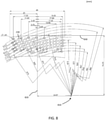
Gemäß weiteren Aspekten sind die Vorsprünge auf versetzten gekrümmten Linien angeordnet. Es hat sich herausgestellt, dass diese Anordnung der Vorsprünge Verbesserungen bei der Schneidleistung erzielt. Die gekrümmten Linien können z. B. durch von einem Kreis mit einer Mitte, die von einer Längsmittellinie des Schneidsegments und von einer oberen Linie des Schneidsegments verschoben worden ist, gezeichnete Kreissegmente bereitgestellt werden, wie nachstehend erläutert wird. Diese spezielle Anordnung der Vorsprünge verbessert die Schneidleistung des Schneidsegments bei gleichbleibend leichter Herstellung.In other aspects, the protrusions are arranged on staggered curved lines. It has been found that this arrangement of the projections achieves improvements in cutting performance. The curved lines can e.g. B. be provided by circle segments drawn from a circle with a center offset from a longitudinal center line of the cutting segment and from a top line of the cutting segment, as will be explained below. This special arrangement of the protrusions improves the cutting performance of the cutting segment while remaining easy to manufacture.
Gemäß weiteren Aspekten ist eine Vertiefung mit einer lateralen Erstreckung in der Schneidfläche ausgebildet. Es hat sich herausgestellt, dass diese Vertiefung Unterschneidungseffekte reduziert, was von Vorteil ist.According to further aspects, an indentation with a lateral extent is formed in the cutting surface. This indentation has been found to reduce undercutting effects, which is beneficial.
In einer Ausführungsform umfasst ein erster Anteil der Vorsprünge mindestens ein jeweiliges Diamantkorn und/oder ein zweiter Anteil der Vorsprünge umfasst kein Diamantkorn.In one embodiment, a first portion of the protrusions includes at least one respective diamond grit and/or a second portion of the protrusions does not include a diamond grit.
In einer Ausführungsform sind die Vorsprünge dahingehend angeordnet, das Abführen von Staub und Schlamm aus einem Schneidbereich des Schneidsegments während des Betriebs zu fördern.In one embodiment, the projections are arranged to promote the evacuation of dust and mud from a cutting area of the cutting segment during operation.
In einer Ausführungsform sind die Vorsprünge so konfiguriert, dass sie verschiedene Formen und Größen aufweisen und/oder unterschiedliche geometrische Formen aufweisen.In one embodiment, the protrusions are configured to have different shapes and sizes and/or have different geometric shapes.
In einer Ausführungsform sind die Vorsprünge mit einem Grundradius zwischen 0,3 mm und 1,0 mm und vorzugsweise etwa 0,70 mm konfiguriert.In one embodiment, the protrusions are configured with a base radius between 0.3 mm and 1.0 mm, and preferably about 0.70 mm.
In einer Ausführungsform ist mindestens einer der Vorsprünge innerhalb einer Fläche auf seiner jeweiligen Seitenfläche von 0,28 mm2 bis 3,14 mm2 positioniert.In one embodiment, at least one of the protrusions is positioned within an area on its respective side surface from 0.28 mm 2 to 3.14 mm 2 .
In einer Ausführungsform werden die Vorsprünge von jeweiligen Vorsprunggrenzen auf den Seitenflächenebenen begrenzt, wobei die Grenzen von der Schneidfläche durch eine Beabstandung abgetrennt werden, und wobei sich ein Abschnitt der Seitenfläche zwischen mindestens zwei Vorsprunggrenzen befindet.In one embodiment, the protrusions are bounded by respective protrusion boundaries at the face planes, the boundaries being separated from the cutting face by a spacing, and a portion of the face is located between at least two protrusion boundaries.
In einer Ausführungsform wird eine Größe der Diamantkörner so gewählt, dass sie in der Größenordnung der Vorsprünge liegt.In one embodiment, a size of the diamond grains is chosen to be of the order of the protrusions.
In einer Ausführungsform wird die Größe der Diamantkörner so gewählt, dass sie kleiner als die Vorsprünge ist.In one embodiment, the diamond grains are sized to be smaller than the protrusions.
In einer Ausführungsform erstrecken sich die Seitenflächen entlang jeweiligen Seitenflächenebenen, wobei sich die Vorsprünge aus den Seitenflächenebenen heraus in der lateralen Richtung von dem Schneidsegment weg erstrecken.In one embodiment, the side surfaces extend along respective side surface planes, with the protrusions extending out of the side surface planes in the lateral direction away from the cutting segment.
In einer Ausführungsform ist mindestens einer der Vorsprünge dahingehend angeordnet, sich lateral über das Sägeblatt hinaus zu erstrecken.In one embodiment, at least one of the projections is arranged to extend laterally beyond the saw blade.
In einer Ausführungsform ist der Schneidfläche ein Normalvektor zugeordnet, der sich normal zur Schneidfläche entgegengesetzt zur Schneidrichtung des Schneidsegments erstreckt, wobei mindestens einer der Vorsprünge eine begrenzte Erstreckung entlang dem Normalvektor der Schneidfläche aufweist.In one embodiment, the cutting surface is associated with a normal vector extending normal to the cutting surface in the opposite direction to the cutting direction of the cutting segment, with at least one of the projections having a finite extent along the normal vector of the cutting surface.
Die Aufgabe wird auch gelöst durch ein Sägeblatt, das mehrere Schneidsegmente gemäß Obigem umfasst, die entlang einem Peripherierand des Sägeblatts angeordnet sind. Dieses Sägeblatt kann kosteneffizient hergestellt werden und bietet eine exzellente Schneidleistung im Hinblick auf die Schneidgeschwindigkeit. Einige Aspekte des vorgeschlagenen Sägeblatts bieten Verbesserungen von bis zu oder sogar mehr als 20 % bei der Schneidgeschwindigkeit und eine Erhöhung von etwa 10 % bei der Schneidsegmentlebensdauer im Vergleich zu einigen bekannten Sägeblättern.The object is also achieved by a saw blade comprising a plurality of cutting segments according to the above arranged along a peripheral edge of the saw blade. This saw blade can be manufactured cost-effectively and offers excellent cutting performance in terms of cutting speed. Some aspects of the proposed saw blade offer improvements of up to or even more than 20% in cutting speed and an increase of about 10% in cutting segment life compared to some known saw blades.
In einer Ausführungsform sind die entlang dem Peripherierand des Sägeblatts angeordneten Schneidsegmente von mindestens zwei Arten, wobei die Schneidsegmente der mindestens zwei Arten entlang dem Peripherierand des Sägeblatts verschachtelt sind.In one embodiment, the cutting segments disposed along the peripheral edge of the saw blade are of at least two types, with the cutting segments of the at least two types being nested along the peripheral edge of the saw blade.
In einer Ausführungsform umfasst eine erste Art von Schneidsegment die Längsabnutzungsanzeigenut, die sich in der Schneidrichtung des Sägeblatts erstreckt und lateral zur Schneidrichtung weist.In one embodiment, a first type of cutting segment includes the longitudinal wear indicator groove extending in the cutting direction of the saw blade and facing lateral to the cutting direction.
In einer Ausführungsform umfasst eine zweite Art von Schneidsegment eine Vertiefung, die mit einer lateralen Erstreckung in der Schneidfläche ausgebildet ist.In one embodiment, a second type of cutting segment includes an indentation formed with a lateral extent in the cutting surface.
In einer Ausführungsform weist eine dritte Art von Schneidsegment eine Höhe auf, die größer als mindestens ein anderes Schneidsegment an dem Sägeblatt ist.In one embodiment, a third type of cutting segment has a height that is greater than at least one other cutting segment on the saw blade.
Die Erfindung umfasst auch ein Arbeitswerkzeug mit einem erfindungsgemäßen Sägeblatt.The invention also includes a working tool with a saw blade according to the invention.
Gemäß weiteren Aspekten sind die entlang dem Peripherierand des Sägeblatts angeordneten Schneidsegmente von mindestens zwei Arten, wobei die Schneidsegmente der mindestens zwei Arten entlang dem Peripherierand des Sägeblatts verschachtelt sind. Durch das Anordnen verschiedener Arten von Schneidsegmenten entlang der Peripherie des Sägeblatts kann das Sägeblatt für verschiedene Materialarten für einfaches und kosteneffizientes Schneiden optimiert werden, da lediglich einige Schneidsegmentarten für einen großen Bereich von verschiedenen Optimierungen erforderlich sind.In further aspects, the cutting segments disposed along the peripheral edge of the saw blade are of at least two types, wherein the cutting segments of the at least two types are nested along the peripheral edge of the saw blade. By arranging different types of cutting segments along the periphery of the saw blade, the saw blade can be optimized for different types of material for easy and cost-effective cutting, since only a few types of cutting segments are required for a wide range of different optimizations.
Hier werden auch Arbeitswerkzeuge und Baugeräte, die mit den oben erwähnten Vorteilen in Zusammenhang stehen, offenbart.Working tools and construction equipment related to the above-mentioned advantages are also disclosed here.
Allgemein sind alle in den Ansprüchen verwendeten Begriffe entsprechend ihren gebräuchlichen Bedeutungen in dem technischen Gebiet zu interpretieren, sofern hier nicht ausdrücklich etwas anderes definiert wird. Alle Bezugnahmen auf „ein/eine/einen/das/die/den Element, Einrichtung, Komponente, Mittel, Schritt usw.“ sind offen so zu interpretieren, dass sie sich auf mindestens ein Vorkommen des Elements, der Einrichtung, der Komponente, des Mittels, des Schritts usw. beziehen, es sei denn, es wird ausdrücklich etwas Gegenteiliges angegeben. Weitere Merkmale und Vorteile der vorliegenden Erfindung werden bei Betrachtung der anhängigen Ansprüche und der folgenden Beschreibung offensichtlich. Der Fachmann erkennt, dass verschiedene Merkmale der vorliegenden Erfindung zur Schaffung von Ausführungsformen, bei denen es sich nicht um jene, die im Folgenden beschrieben werden, handelt, kombiniert werden können, ohne den Schutzumfang der vorliegenden Erfindung zu verlassen.In general, all terms used in the claims are to be construed according to their customary meanings in the technical field, unless expressly defined otherwise herein. All references to "an element, device, component, means, step, etc." are to be openly construed as referring to at least one occurrence of the element, device, component, step, etc means, step, etc., unless expressly stated otherwise. Further features and advantages of the present invention will become apparent upon consideration of the appended claims and the following description. Those skilled in the art will recognize that various features of the present invention can be combined to create embodiments other than those described below, without departing from the scope of the present invention.
Figurenlistecharacter list
Die vorliegende Offenbarung wird nun unter Bezugnahme auf die anhängigen Zeichnungen genauer beschrieben; in den Zeichnungen zeigen:
-
1A-B ein beispielhaftes Sägeblatt, das Schneidsegmente umfasst; -
2A-D ein Schneidsegment gemäß einem ersten Beispiel; -
3A-F schematisch beispielhafte Vorsprungformen; -
4A-C ein Schneidsegment gemäß einem zweiten Beispiel; -
5A-C ein Schneidsegment gemäß einem dritten Beispiel; -
6A-B ein beispielhaftes Sägeblatt, das Schneidsegmente umfasst; -
7A-B ein weiteres beispielhaftes Sägeblatt, das Schneidsegmente umfasst; -
8 eine Anordnung von Vorsprüngen an einem Schneidsegment; und -
9 eine Anordnung von Vorsprüngen an einem Schneidsegment.
-
1A-B an exemplary saw blade including cutting segments; -
2A-D a cutting segment according to a first example; -
3A-F schematically exemplary protrusion shapes; -
4A-C a cutting segment according to a second example; -
5A-C a cutting segment according to a third example; -
6A-B an exemplary saw blade including cutting segments; -
7A-B another exemplary saw blade that includes cutting segments; -
8th an array of projections on a cutting segment; and -
9 an array of projections on a cutting segment.
DETAILLIERTE BESCHREIBUNGDETAILED DESCRIPTION
Die Erfindung wird nun nachstehend unter Bezugnahme auf die anhängigen Zeichnungen, in denen einige Aspekte der Erfindung gezeigt werden, genauer beschrieben. Diese Erfindung kann jedoch in vielen verschiedenen Arten ausgeführt sein und sollte nicht als auf die hier angeführten Ausführungsformen und Aspekte beschränkend aufgefasst werden; stattdessen werden diese Ausführungsformen als Beispiele bereitgestellt, so dass die vorliegende Offenbarung gründlich und vollständig ist und dem Fachmann den Schutzumfang der Erfindung vollständig vermittelt. Gleiche Bezugszeichen beziehen sich in der Beschreibung durchgehend auf gleiche Elemente.The invention will now be described in more detail below with reference to the accompanying drawings, in which some aspects of the invention are shown. However, this invention may be embodied in many different forms and should not be construed as limited to the embodiments and aspects set forth herein; rather, these embodiments are provided by way of example so that this disclosure will be thorough and complete, and will fully convey the scope of the invention to those skilled in the art. Like reference numbers refer to like elements throughout the description.
Es versteht sich, dass die vorliegende Erfindung nicht auf die hier beschriebenen und in den Zeichnungen dargestellten Ausführungsformen beschränkt ist; stattdessen erkennt der Fachmann, dass viele Änderungen und Modifikationen innerhalb des Schutzumfangs der anhängigen Ansprüche durchgeführt werden können. Dies betrifft insbesondere die beispielhaften Abmessungen der Schneidsegmente und der Sägeblätter, die nachstehend beschrieben werden.It should be understood that the present invention is not limited to the embodiments described herein and illustrated in the drawings; instead, those skilled in the art will recognize that many changes and modifications can be made within the scope of the appended claims. This concerns in particular the exemplary dimensions of the cutting segments and the saw blades, which are described below.
Ein homogenes Gemisch ist hier als ein Gemisch von Partikeln und/oder Körnern, das über eine gegebene Probe hinweg ungefähr dieselben Anteile seiner Komponenten aufweist, zu interpretieren. Es versteht sich, dass die Anteile von Partikeln im gesamten Gemisch aufgrund von Randomisation geringfügig verschieden sein können. Ein homogenes Gemisch aus Metallpulver und Diamantkörnern kann beispielsweise durch Hinzugeben des Metallpulvers und der Diamantkörner in einen Behälter und dann Rühren oder Schütteln des Gemischs, bis ein homogenes Gemisch erhalten wird, erhalten werden.A homogeneous mixture is to be interpreted herein as a mixture of particles and/or granules that has approximately the same proportions of its components throughout a given sample. It is understood that the proportions of particles in the entire mixture can be slightly different due to randomization. A homogeneous mixture of metal powder and diamond grains can be obtained, for example, by adding the metal powder and diamond grains to a container and then stirring or shaking the mixture until a homogeneous mixture is obtained.
Allgemein werden hier Abmessungen in Millimetern (mm) angegeben. Es versteht sich, dass die angegebenen Maße lediglich beispielhaft sind, um zu veranschaulichen, wie die offenbarten Schneidsegmente und Sägeblätter in die Praxis umgesetzt werden können.In general, dimensions are given here in millimeters (mm). It should be understood that the dimensions given are merely exemplary to illustrate how the disclosed cutting segments and saw blades may be put into practice.
Eine Schneidrichtung C des Sägeblatts 100 ist eine Richtung, die von der Mitte des Blatts zu dem Peripherierand E und darüber hinaus verläuft. Dies ist die Richtung, in der das Sägeblatt mit dem zu schneidenden Material in Eingriff gelangt.A cutting direction C of the
Die beabsichtigte Drehrichtung des Sägeblatts wird durch einen Pfeil 120 angezeigt, der optional in das Sägeblatt geschnitten ist oder anderweitig an dem Sägeblatt markiert ist.The intended direction of rotation of the saw blade is indicated by an
Die Schneidsegmente 110 sind durch Schrägschlitze 130 abgetrennt, die in Löchern enden, deren Durchmesser etwas mehr als die Breite des Schrägschlitzes beträgt. Diese Schrägschlitze fördern das Abführen von Staub und Schlamm während des Schneidbetriebs. Die Schrägschlitze können eine Breite von etwa 2 mm und einen Schrägungswinkel von etwa 30 Grad aufweisen. Diese Schrägschlitze fördern das Abführen von Staub und Schlamm und fördern auch das Kühlen der Schneidsegmente während des Schneidbetriebs.The cutting
Messlöcher 140 sind entlang einem Kreis, der auf der Sägeblattmitte 170 zentriert ist und einen kleineren Radius als ein Radius des Sägeblatts aufweist, angeordnet. Die Messlöcher gestatten das Messen von Schneidsegmentabnutzung, z. B. durch Taster.Measurement holes 140 are arranged along a circle centered on
Die Messlöcher 140, die zusammen mit einem zweiten Satz von Löchern 150 auch auf einem Kreis angeordnet sind, bilden eine Schnitttiefenanzeigeanordnung. Der erste Satz von Löchern 140 kann etwa 1 Inch von dem Schneidsegmentrand weg angeordnet sein, und der zweite Satz von Löchern 150 etwa 2 Inch von dem Schneidsegmentrand weg. Auf diese Weise kann ein Bediener visuell die ungefähre Schnitttiefe während des Betriebs bestimmen.The gauge holes 140, also arranged on a circle along with a second set of
Ein Stiftloch 160 ist in Verbindung mit der Blattmitte 170 zur Befestigung des Blatts an einem Werkzeug angeordnet.A
Die Differenz zwischen einer Nut und einem Vorsprung ist in
Das Schneidsegment 110, das von dem Körper 200 und von den Vorsprüngen 230 gebildet wird, wird durch ein homogenes Gemisch aus Metallpulver und Diamantkörnern ausgebildet. D. h., dass die Vorsprünge nicht einzeln an dem Körper angebracht werden, sondern zusammen mit dem Körper einstückig integral ausgebildet werden. Also kann, da das gesamte Schneidsegment durch ein einziges homogenes Gemisch aus Metallpulver und Diamantkörnern ausgebildet wird, es effizient und kosteneffektiv, z. B. durch Kaltpressen des Schneidsegments, hergestellt werden. Einige der Vorsprünge können nach der Herstellung zufällig ein oder mehrere Diamantkörner umfassen, und einige Vorsprünge können nur Metall umfassen. Statistisch umfasst jedoch ein Anteil der vorragenden Elemente Diamantkörner, die das Schneidsegment vor lateraler Abnutzung schützen. Gemäß einigen Aspekten wird die Größe der Diamantkörner so gewählt, dass sie in der Größenordnung der Vorsprünge liegen, jedoch nicht größer als die Vorsprünge sind, da sonst keine Diamantkörner von dem Körper 200 vorragen. Bei Versuchen im Labor hat sich herausgestellt, dass ein Gemisch aus Metallpulver und Diamantkörnern, das zwischen 90 Vol.-% und 97 Vol.-% Metallpulver und dementsprechend zwischen 10 Vol.-% und 3 Vol.-% Diamanten zur Bereitstellung eines effizienten Schneidbetriebs bei einem großen Bereich von Materialien, wie z. B. Stahlbeton und Stein, wünschenswert ist.The cutting
Unter Bezugnahme auf
Gemäß einigen Aspekten sind die Vorsprünge 230 auf versetzten gekrümmten Linien 240A, 240B angeordnet, die schematisch in
Das Schneidsegment 110 umfasst optional des Weiteren eine Längsabnutzungsanzeigenut 250, die sich in der Schneidrichtung C erstreckt und lateral L zur Schneidrichtung C weist. Eine Querschnittsansicht durch diese Längsabnutzungsanzeigenut wird in
Es hat sich herausgestellt, dass die Kombination aus der Längsabnutzungsanzeigenut und den Vorsprüngen ein besonders effektives Schneidsegment erzielt.It has been found that the combination of the longitudinal wear indicator groove and the projections results in a particularly effective cutting segment.
Das Schneidsegment 110 umfasst optional des Weiteren eine Lateralabnutzungsanzeigenut 260, die in einer oder beiden der Seitenflächen 220 ausgebildet ist und lateral L zur Schneidrichtung C weist. Die laterale Tiefe der Lateralabnutzungsanzeigenut 260 zeigt eine zulässige laterale Abnutzung des Schneidsegments 110 an und kann von dem Konstrukteur des Sägeblatts entsprechend der Art von Schneidsegment und beabsichtigter Verwendung konfiguriert werden. Somit kann ein Bediener visuell die gegenwärtige laterale Abnutzung erkennen und somit bestimmen, wann es Zeit ist, das Sägeblatt zu ersetzen.The cutting
Es hat sich herausgestellt, dass die Kombination aus der Lateralabnutzungsanzeigenut und den Vorsprüngen ein besonders effektives Schneidsegment erzielt.It has been found that the combination of the lateral wear indicator groove and the projections results in a particularly effective cutting segment.
Sowohl die Längs- als auch die Lateralabnutzungsanzeige erleichtern auch das Abführen von Staub und Schlamm aus dem Schneidbereich, indem Staub und Schlamm hinaus und von dem Schnitt weg transportiert werden, während sich das Sägeblatt dreht.Both the longitudinal and lateral wear indicators also make it easier to clear dust and mud from the cutting area by transporting dust and mud out and away from the cut as the saw blade rotates.
Die laterale Tiefe der Lateralabnutzungsanzeigenut 260 kann in der Größenordnung von zwischen 0,3 mm und 0,7 mm und vorzugsweise etwa 0,5 mm liegen.The lateral depth of the lateral
Die Höhe und Breite der Lateralabnutzungsanzeigenut 260 können auf zwischen 2 mm und 4 mm und 3,5 mm und 5,5 mm und vorzugsweise 3 mm bzw. 4,75 mm konfiguriert sein.The height and width of the lateral
Es versteht sich, dass die Vorsprünge 230 mit unterschiedlichen geometrischen Formen ausgebildet sein können.
Es versteht sich, dass sich ein Vorsprung von einer in der Seitenfläche ausgebildeten Nut unterscheidet. Während sich ein Vorsprung lateral aus der Seitenfläche heraus erstreckt, erstreckt sich eine Nut lateral nach innen zur Mitte des Schneidsegments hin. Wie in
Die Schneidsegmentkörperbreite 280 kann zwischen 3,5 mm und 4,0 mm und vorzugsweise 3,7 mm betragen, wie in
Ein Vorsprung ist auch auf der Seitenfläche positioniert, wohingegen eine Nut länglich ist und eine Erstreckungsrichtung aufweist, entlang der sie sich erstreckt. Gemäß einigen Aspekten werden die hier erörterten Vorsprünge durch eine jeweilige Vorsprunggrenze auf eine Fläche auf der Seitenfläche von 0,28 mm2 bis 3,14 mm2 für die runden Vorsprünge beschränkt, was gemäß einigen Aspekten auch für andere Formen von Vorsprüngen gilt. Die Vorsprünge werden von Vorsprunggrenzen auf den Seitenflächenebenen P1, P2 begrenzt, und die Grenzen sind von der Schneidfläche 210 durch eine Beabstandung abgetrennt. Anders ausgedrückt befindet sich ein Abschnitt der Seitenfläche 220 zwischen mindestens zwei Vorsprüngen 230 und vorzugsweise zwischen beliebigen zwei Vorsprüngen oder zumindest zwischen einem Großteil der Vorsprünge.A protrusion is also positioned on the side surface, whereas a groove is elongate and has a direction of extension along which it extends. In some aspects, the protrusions discussed herein are constrained by a respective protrusion limit to an area on the side surface from 0.28 mm 2 to 3.14 mm 2 for the round protrusions, which in some aspects also applies to other protrusion shapes. The protrusions are bounded by protrusion boundaries on the side surface planes P1, P2 and the boundaries are separated from the cutting
Allgemein wird ein Vorsprung unabhängig von seiner geometrischen Form auf eine Fläche auf der Seitenfläche von 0,28 mm2 bis 3,14 mm2 beschränkt. Dies bedeutet, dass die Seiten S1 und S2 in der Größenordnung des Doppelten des Radius R liegen, wie in
Die hier offenbarten Schneidsegmente umfassen eine Schneidfläche 210. Dieser Schneidfläche ist ein Normalvektor zugeordnet, der sich in dem Beispiel von
Die Vorsprünge 230 können wie oben erwähnt in unterschiedlichen geometrischen Formen ausgebildet sein. Jeder solchen Form ist eine geometrische Mitte oder ein Schwerpunkt, d. h. eine arithmetische Mittelwertposition all der Punkte in der Form, zugeordnet. Bei den hier offenbarten Schneidsegmenten, die z. B. durch
Es hat sich herausgestellt, dass die Vertiefung 420 solche Unterschneidungseffekte reduziert, wobei es sich um einen Vorteil handelt.
Eine dritte Art von Schneidsegment 510 weist optional eine Höhe 270 auf, die größer als mindestens ein anderes Schneidsegment an dem Sägeblatt 700 ist, wie in
ZITATE ENTHALTEN IN DER BESCHREIBUNGQUOTES INCLUDED IN DESCRIPTION
Diese Liste der vom Anmelder aufgeführten Dokumente wurde automatisiert erzeugt und ist ausschließlich zur besseren Information des Lesers aufgenommen. Die Liste ist nicht Bestandteil der deutschen Patent- bzw. Gebrauchsmusteranmeldung. Das DPMA übernimmt keinerlei Haftung für etwaige Fehler oder Auslassungen.This list of documents cited by the applicant was generated automatically and is included solely for the better information of the reader. The list is not part of the German patent or utility model application. The DPMA assumes no liability for any errors or omissions.
Zitierte PatentliteraturPatent Literature Cited
- US 2010291845 [0005]US2010291845 [0005]
- US 20060130823 A1 [0005, 0067]US20060130823 A1 [0005, 0067]
- WO 2002066217 A1 [0005, 0067]WO 2002066217 A1 [0005, 0067]
Claims (15)
Applications Claiming Priority (2)
| Application Number | Priority Date | Filing Date | Title |
|---|---|---|---|
| SE2050932A SE2050932A1 (en) | 2020-08-04 | 2020-08-04 | Improved cutting segments for abrasive cutting tools |
| SE2050932-9 | 2020-08-04 |
Publications (1)
| Publication Number | Publication Date |
|---|---|
| DE102021120198A1 true DE102021120198A1 (en) | 2022-02-10 |
Family
ID=77358255
Family Applications (1)
| Application Number | Title | Priority Date | Filing Date |
|---|---|---|---|
| DE102021120198.5A Withdrawn DE102021120198A1 (en) | 2020-08-04 | 2021-08-03 | Improved cutting segments for cut-off tools |
Country Status (4)
| Country | Link |
|---|---|
| US (1) | US20230278259A1 (en) |
| DE (1) | DE102021120198A1 (en) |
| SE (1) | SE2050932A1 (en) |
| WO (1) | WO2022029144A1 (en) |
Families Citing this family (3)
| Publication number | Priority date | Publication date | Assignee | Title |
|---|---|---|---|---|
| USD1037808S1 (en) | 2021-09-23 | 2024-08-06 | C.M.T. Utensili S.P.A. | Cutting disc |
| WO2023249602A1 (en) * | 2022-06-20 | 2023-12-28 | Husqvarna Ab | U-shaped cutting segments for abrasive cutting tools |
| USD1119491S1 (en) * | 2023-07-11 | 2026-03-24 | Hilti Aktiengesellschaft | Part of a diamond saw blade |
Citations (3)
| Publication number | Priority date | Publication date | Assignee | Title |
|---|---|---|---|---|
| WO2002066217A1 (en) | 2001-02-20 | 2002-08-29 | Ehwa Diamond Ind. Co., Ltd. | Machining tips and cutting wheel, grinding wheel and drilling wheel therewith |
| US20060130823A1 (en) | 2003-03-06 | 2006-06-22 | Kim Soo K | Gear type machining tip and tool attaching the same thereon |
| US20100291845A1 (en) | 2006-11-16 | 2010-11-18 | Shinhan Diamond Ind. Co., Ltd. | Diamond tool |
Family Cites Families (14)
| Publication number | Priority date | Publication date | Assignee | Title |
|---|---|---|---|---|
| US5190568B1 (en) * | 1989-01-30 | 1996-03-12 | Ultimate Abrasive Syst Inc | Abrasive tool with contoured surface |
| DE4243017A1 (en) * | 1992-12-18 | 1994-06-23 | Hilti Ag | Disc-shaped grinding tool |
| US5518443A (en) * | 1994-05-13 | 1996-05-21 | Norton Company | Superabrasive tool |
| DE19810511B4 (en) * | 1998-03-11 | 2006-12-28 | Scintilla Ag | Tool with a plurality of cutting segments for working stone, masonry or concrete |
| KR100426843B1 (en) * | 2000-11-13 | 2004-04-13 | 박인순 | Method and apparatus for manufacturing cutting blades, and a cutting blade manufactured by the same |
| JP2002254321A (en) * | 2001-02-28 | 2002-09-10 | Noritake Co Ltd | Segmented grinding wheel |
| DE20104395U1 (en) * | 2001-03-10 | 2001-07-26 | didia Diamanttechnik GmbH, 95032 Hof | Segments for machine cutting and cutting tools |
| US6932076B2 (en) * | 2003-10-17 | 2005-08-23 | Chien-Cheng Liao | Diamond circular saw blade |
| KR100466510B1 (en) * | 2004-05-10 | 2005-01-15 | 신한다이아몬드공업 주식회사 | Metal plate insert type diamond tools |
| DE202005016385U1 (en) * | 2005-10-19 | 2006-01-12 | Heger Gmbh European Diamand Tools | Cut-off wheel and grinding segment for this |
| US7353819B2 (en) * | 2005-12-23 | 2008-04-08 | Dong Young Diamond Industrial Co., Ltd. | Processing tips and tools using the same |
| KR20100005412U (en) * | 2008-11-18 | 2010-05-27 | 형운다이아몬드공업주식회사 | A diamond tip for a saw blade cutting stones |
| JP6844430B2 (en) * | 2017-06-09 | 2021-03-17 | 信越化学工業株式会社 | Peripheral cutting blade and its manufacturing method |
| EP3670050A1 (en) * | 2018-12-21 | 2020-06-24 | Hilti Aktiengesellschaft | Processing segment for a machining tool |
-
2020
- 2020-08-04 SE SE2050932A patent/SE2050932A1/en not_active Application Discontinuation
-
2021
- 2021-08-03 WO PCT/EP2021/071700 patent/WO2022029144A1/en not_active Ceased
- 2021-08-03 DE DE102021120198.5A patent/DE102021120198A1/en not_active Withdrawn
- 2021-08-03 US US18/018,076 patent/US20230278259A1/en active Pending
Patent Citations (3)
| Publication number | Priority date | Publication date | Assignee | Title |
|---|---|---|---|---|
| WO2002066217A1 (en) | 2001-02-20 | 2002-08-29 | Ehwa Diamond Ind. Co., Ltd. | Machining tips and cutting wheel, grinding wheel and drilling wheel therewith |
| US20060130823A1 (en) | 2003-03-06 | 2006-06-22 | Kim Soo K | Gear type machining tip and tool attaching the same thereon |
| US20100291845A1 (en) | 2006-11-16 | 2010-11-18 | Shinhan Diamond Ind. Co., Ltd. | Diamond tool |
Also Published As
| Publication number | Publication date |
|---|---|
| US20230278259A1 (en) | 2023-09-07 |
| WO2022029144A1 (en) | 2022-02-10 |
| SE2050932A1 (en) | 2022-02-05 |
Similar Documents
| Publication | Publication Date | Title |
|---|---|---|
| DE4324411B4 (en) | Saw blade for metal cutting | |
| DE102021120198A1 (en) | Improved cutting segments for cut-off tools | |
| DE202009018703U1 (en) | Road leveling tip with washer | |
| DE102007054600B4 (en) | Saw blade with a basic body and teeth with cutting edges | |
| DE10317760A1 (en) | Milling tool and insert for such | |
| DE3300791A1 (en) | SAW BLADE | |
| DE102007054601A1 (en) | Saw blade with a basic body and teeth with cutting edges | |
| DE2516147A1 (en) | CUTTING INSERT FOR A STONE CUTTING TOOL | |
| DE1502019A1 (en) | Tools and tooling made of sintered hard metal | |
| EP3356073B1 (en) | Band saw blade having a chip-splitting tooth | |
| DE2058468A1 (en) | Abrasive cutting saw blade | |
| DE102007034087A1 (en) | Milling cutter for machining workpiece, has roughing blades and finishing blade provided with blade edges, where blades are arranged in block, and teeth of blade edges on blades axially displaced to each other | |
| EP0287847B1 (en) | Cutting tool | |
| DE8420322U1 (en) | Grinding wheel | |
| DE3114687A1 (en) | Cutting blade | |
| DE2436596B2 (en) | BLADE FOR CYLINDRICAL TOOLS FOR REMOVING RUBBER OR RUBBER-LIKE MATERIAL | |
| DE2755426A1 (en) | CRUSHING PLATE FOR JAW CRUSHERS | |
| DE10253711B4 (en) | sawblade | |
| DE19638718C1 (en) | Saw blade for slot cutting device, used in road and floor surfaces of asphalt, concrete and like | |
| EP3444072A1 (en) | Dressing tool comprising a metallic base body with an outer edge or circumferential surface with hard elements | |
| DE102018123117A1 (en) | Tangentially tipped circular saw blade and process for resharpening it | |
| DE102015223428B4 (en) | Cut-off wheel, use of a cut-off wheel and method for cutting a workpiece by means of cut-off grinding | |
| DE69314716T2 (en) | Circular saw blade | |
| DE8321789U1 (en) | CUTTING WHEEL | |
| DE2213811A1 (en) | DIAMOND SAW FOR NATURAL, ARTIFICIAL STONE AND CONCRETE BODY |
Legal Events
| Date | Code | Title | Description |
|---|---|---|---|
| R012 | Request for examination validly filed | ||
| R016 | Response to examination communication | ||
| R119 | Application deemed withdrawn, or ip right lapsed, due to non-payment of renewal fee |