DE102021110421B3 - Hand trolley for direct loading into a motor vehicle - Google Patents

Hand trolley for direct loading into a motor vehicle Download PDF

Info

Publication number
DE102021110421B3
DE102021110421B3 DE102021110421.1A DE102021110421A DE102021110421B3 DE 102021110421 B3 DE102021110421 B3 DE 102021110421B3 DE 102021110421 A DE102021110421 A DE 102021110421A DE 102021110421 B3 DE102021110421 B3 DE 102021110421B3
Authority
DE
Germany
Prior art keywords
handcart
frame element
longitudinal beam
longitudinal
bolt
Prior art date
Legal status (The legal status is an assumption and is not a legal conclusion. Google has not performed a legal analysis and makes no representation as to the accuracy of the status listed.)
Active
Application number
DE102021110421.1A
Other languages
German (de)
Inventor
Patentinhaber gleich
Current Assignee (The listed assignees may be inaccurate. Google has not performed a legal analysis and makes no representation or warranty as to the accuracy of the list.)
Individual
Original Assignee
Individual
Priority date (The priority date is an assumption and is not a legal conclusion. Google has not performed a legal analysis and makes no representation as to the accuracy of the date listed.)
Filing date
Publication date
Application filed by Individual filed Critical Individual
Priority to DE102021110421.1A priority Critical patent/DE102021110421B3/en
Application granted granted Critical
Publication of DE102021110421B3 publication Critical patent/DE102021110421B3/en
Priority to EP22162409.1A priority patent/EP4079601A1/en
Active legal-status Critical Current
Anticipated expiration legal-status Critical

Links

Images

Classifications

    • BPERFORMING OPERATIONS; TRANSPORTING
    • B62LAND VEHICLES FOR TRAVELLING OTHERWISE THAN ON RAILS
    • B62BHAND-PROPELLED VEHICLES, e.g. HAND CARTS OR PERAMBULATORS; SLEDGES
    • B62B5/00Accessories or details specially adapted for hand carts
    • B62B5/0003Adaptations for loading in or on a vehicle
    • BPERFORMING OPERATIONS; TRANSPORTING
    • B62LAND VEHICLES FOR TRAVELLING OTHERWISE THAN ON RAILS
    • B62BHAND-PROPELLED VEHICLES, e.g. HAND CARTS OR PERAMBULATORS; SLEDGES
    • B62B3/00Hand carts having more than one axis carrying transport wheels; Steering devices therefor; Equipment therefor
    • B62B3/02Hand carts having more than one axis carrying transport wheels; Steering devices therefor; Equipment therefor involving parts being adjustable, collapsible, attachable, detachable or convertible
    • B62B3/027Hand carts having more than one axis carrying transport wheels; Steering devices therefor; Equipment therefor involving parts being adjustable, collapsible, attachable, detachable or convertible collapsible shopping trolleys
    • BPERFORMING OPERATIONS; TRANSPORTING
    • B62LAND VEHICLES FOR TRAVELLING OTHERWISE THAN ON RAILS
    • B62BHAND-PROPELLED VEHICLES, e.g. HAND CARTS OR PERAMBULATORS; SLEDGES
    • B62B2205/00Hand-propelled vehicles or sledges being foldable or dismountable when not in use
    • B62B2205/10Detachable wheels
    • B62B2205/104Detachable wheel units, e.g. together with the wheel shaft
    • BPERFORMING OPERATIONS; TRANSPORTING
    • B62LAND VEHICLES FOR TRAVELLING OTHERWISE THAN ON RAILS
    • B62BHAND-PROPELLED VEHICLES, e.g. HAND CARTS OR PERAMBULATORS; SLEDGES
    • B62B2205/00Hand-propelled vehicles or sledges being foldable or dismountable when not in use
    • B62B2205/20Catches; Locking or releasing an articulation

Landscapes

  • Engineering & Computer Science (AREA)
  • Chemical & Material Sciences (AREA)
  • Combustion & Propulsion (AREA)
  • Transportation (AREA)
  • Mechanical Engineering (AREA)
  • Handcart (AREA)

Abstract

Die Erfindung betrifft einen Handwagen zum direkten Verladen in ein Kraftfahrzeug, insbesondere in den Laderaum eines Kraftfahrzeugs, wobei der Handwagen ein einklappbares Fahrwerk mit einem ersten Rahmenelement und einem zweiten Rahmenelement mit daran angeordneten Rädern aufweist, das an einem ersten Längsträger und einem, über ein Grundelement (1) mit dem ersten Längsträger verbundenen parallelen zweiten Längsträger schwenkbar gelagert ist, wobei das erste Rahmenelement mittels einer Achse in einer Bohrung der Längsträger und das zweite Rahmenelement in einer Führung entlang der Längsträger verschiebbar gelagert ist und wobei die Längsträger je einen ersten Endbereich und einen, dem ersten Endbereich gegenüberliegenden, zweiten Endbereich aufweisen, wobei im ersten Endbereich je Längsträger ein Rollelement angeordnet ist, auf dem der Handwagen in den Kofferraum schiebbar ist und im zweiten Endbereich je Längsträger ein Gelenkpunkt für eine Abstützstrebe des hinteren Rahmenelements und eines Schiebegriffelements angeordnet ist derart, dass im zusammengeklappten Zustand das Schiebergriffelement auf im Wesentlichen die Höhe des Grundelements klappbar ist.The invention relates to a handcart for direct loading into a motor vehicle, in particular in the loading space of a motor vehicle, the handcart having a retractable chassis with a first frame element and a second frame element with wheels arranged thereon, which is attached to a first longitudinal member and a base element (1) the parallel second longitudinal beam connected to the first longitudinal beam is pivotably mounted, the first frame element being mounted displaceably by means of an axis in a bore of the longitudinal beam and the second frame element in a guide along the longitudinal beam, and wherein the longitudinal beams each have a first end region and a , the first end region opposite, second end region, wherein in the first end region per longitudinal member a rolling element is arranged on which the handcart can be pushed into the trunk and in the second end region per longitudinal member a hinge point for a support strut of the rear frame element u nd a push handle element is arranged such that in the folded state the slide handle element can be folded to essentially the height of the base element.

Description

Die Erfindung betrifft einen Handwagen zum direkten Verladen in ein Kraftfahrzeug und findet insbesondere für die Verladung in einen Kofferraum eines Kraftfahrzeuges ohne erneutes Umpacken der Waren Anwendung.The invention relates to a handcart for direct loading into a motor vehicle and is used in particular for loading into a trunk of a motor vehicle without repacking the goods.

Die Druckschrift DE 10 2010 022 452 A1 offenbart einen Handwagen, insbesondere einen Einkaufswagen, mit wenigstens einem Behältnis zur Aufnahme und/oder zum Transport von Gegenständen und mit wenigstens einem das Behältnis tragenden Fahrgestell zum Verfahren des Behältnisses. Des Weiteren weist der Handwagen wenigstens eine Schiebeeinrichtung mit einem Griff und einem Griffbereich auf, mittels dessen ein manuelles Schieben und/oder Ziehen erfolgt.The pamphlet DE 10 2010 022 452 A1 discloses a handcart, in particular a shopping cart, with at least one container for receiving and / or for transporting objects and with at least one chassis carrying the container for moving the container. Furthermore, the handcart has at least one pushing device with a handle and a grip area, by means of which manual pushing and / or pulling takes place.

Das Fahrgestell weist wenigstens ein gegenüber dem Behältnis zumindest zwischen wenigstens zwei Stellungen hin und her bewegbares Fahrgestellelement auf.The chassis has at least one chassis element that can be moved back and forth with respect to the container at least between at least two positions.

Aus der Druckschrift DE 20 2010 014 136 U1 ist ein faltbarer Einkaufswagen bekannt, wobei je zwei der Räder in einem Radrahmen angebracht sind, die unter dem faltbaren Warenkorb raumsparend beigeklappt werden können.From the pamphlet DE 20 2010 014 136 U1 a foldable shopping cart is known, two of the wheels being mounted in a wheel frame, which can be folded under the foldable shopping cart to save space.

Das Gefährt weist zusätzliche Rollen zur rollenden Bewegung der Last im Laderaum von Fahrzeugen auf, wobei diese an dem vorderen Radrahmen ausgebildet sind und bei eingeklapptem Radrahmen auf der Ladefläche des Fahrzeuges aufliegen. Nachteilig ist, dass diese Art des Einkaufswagens im Kofferraum kippen und verrutschen kann, da die Auflagefläche durch die Rollen sehr klein ist.The vehicle has additional rollers for the rolling movement of the load in the loading space of vehicles, these being formed on the front wheel frame and resting on the loading area of the vehicle when the wheel frame is folded in. The disadvantage is that this type of shopping trolley can tilt and slip in the trunk, since the bearing surface is very small due to the rollers.

In der Druckschrift FR 2 850 623 A1 wird ein Einkaufswagen beschrieben, der ein vorderes und ein hinteres Traggestell aufweist, wobei das hintere Traggestell einen Drehpunkt am Einkaufskorb aufweist und im verladenen Zustand um den Einkaufskorb schwenkbar ist, so dass die Rollen oberhalb des Einkaufskorbes angeordnet sind. Eine derartige Ausgestaltung benötigt jedoch viel Platz in einem Laderaum, insbesondere in dessen Höhe. Der Einkaufskorb ist starr und kann nicht in seiner Größe reduziert werden.In the pamphlet FR 2 850 623 A1 A shopping cart is described which has a front and a rear support frame, the rear support frame having a pivot point on the shopping basket and being pivotable around the shopping basket when loaded so that the rollers are arranged above the shopping basket. Such a configuration, however, requires a lot of space in a cargo space, especially at its height. The shopping basket is rigid and cannot be reduced in size.

Ein weiteres faltbares System für ein Fahrgestell eines Einkaufswagens ist aus der Druckschrift FR 2 775 645 B1 bekannt. Das offenbarte System weist jedoch einen komplizierten Aufbau mit mehreren Getriebeelementen auf. Des Weiteren ist der Platzbedarf in einem Laderaum sehr groß.Another foldable system for a chassis of a shopping trolley is from the document FR 2 775 645 B1 known. However, the disclosed system has a complicated structure with multiple transmission elements. Furthermore, the space required in a cargo space is very large.

Die Druckschrift DE 10 2008 031 541 A1 beschreibt einen Transportwagen, insbesondere einen Einkaufswagen, der ein zusammenklappbares Fahrgestell aufweist. Gemäß der Ausgestaltung weist der Einkaufswagen ein Gestell und einen Einkaufskorb auf, die getrennt voneinander gelagert und transportiert werden können. Der Einkaufskorb ist ebenfalls klappbar auf dem Fahrgestell befestigbar. Nachteilig sind der große Platzbedarf und die fehlende Möglichkeit, den Einkaufswagen beladen in einen Laderaum eines Fahrzeugs hineinzuschieben.The pamphlet DE 10 2008 031 541 A1 describes a transport trolley, in particular a shopping trolley, which has a collapsible chassis. According to the embodiment, the shopping cart has a frame and a shopping basket, which can be stored and transported separately from one another. The shopping basket can also be attached to the chassis in a foldable manner. Disadvantages are the large amount of space required and the lack of the possibility of pushing the loaded shopping trolley into a loading space of a vehicle.

Die Druckschrift FR 2 971 220 A1 beschreibt einen Handwagen, der zusammenfaltbar ist, wobei der Handwagen eine obere und eine parallele untere Ebene aufweist, die über Streben miteinander verbunden sind. Je nach Positionierung der Streben kann der Abstand zwischen der unteren und oberen Ebene eingestellt werden. Der Handwagen weist an seiner Unterseite Rollen auf, mittels derer er verschiebbar ist. Diese Ausgestaltung weist einerseits einen sehr großen Platzbedarf im gefalteten Zustand und andererseits keine Möglichkeit auf, den Handwagen in einen Laderaum zu schieben.The pamphlet FR 2 971 220 A1 describes a handcart which is collapsible, the handcart having an upper and a parallel lower level which are connected to one another by struts. Depending on the positioning of the struts, the distance between the lower and upper levels can be adjusted. The handcart has rollers on its underside, by means of which it can be moved. This embodiment, on the one hand, requires a very large amount of space in the folded state and, on the other hand, has no possibility of pushing the handcart into a loading space.

Ein Transportwagen für Lastgüter ist aus der Druckschrift FR 2 987 592 B1 bekannt. Der Transportwagen weist einen Faltmechanismus für das Zusammengelegen der oberen und unteren Ebene auf. Jedoch ist der Transportwagen nicht für einen Einkaufskorb oder den Einsatz in einem Fahrzeug geeignet.A transport trolley for goods is from the publication FR 2 987 592 B1 known. The trolley has a folding mechanism for bringing the upper and lower levels together. However, the trolley is not suitable for a shopping basket or use in a vehicle.

Aufgabe der Erfindung ist es, einen Handwagen zum direkten Verladen in ein Kraftfahrzeug zu entwickeln, welcher einen einfachen konstruktiven Aufbau aufweist und im zusammengeklappten Zustand einen gegenüber dem Stand der Technik geringeren Platzbedarf hat.The object of the invention is to develop a handcart for direct loading into a motor vehicle, which has a simple structural design and, in the folded state, requires less space than in the prior art.

Diese Aufgabe wird mit den Merkmalen des ersten Patentanspruchs gelöst.This object is achieved with the features of the first claim.

Vorteilhafte Ausgestaltungen ergeben sich aus den Unteransprüchen.Advantageous refinements result from the subclaims.

Der Handwagen zum direkten Verladen in ein Kraftfahrzeug, insbesondere in den Laderaum eines Kraftfahrzeugs, weist ein einklappbares Fahrwerk mit einem ersten Rahmenelement und einem zweiten Rahmenelement mit daran angeordneten Rädern auf, das an einem ersten Längsträger und einem, über ein Grundelement mit dem ersten Längsträger verbundenen parallelen zweiten Längsträger schwenkbar gelagert ist. Das erste Rahmenelement mittels einer Achse in einer Bohrung der Längsträger und das zweite Rahmenelement in einer Führung entlang der Längsträger verschiebbar gelagert. Die Längsträger weisen je einen ersten Endbereich und einen, dem ersten Endbereich gegenüberliegenden, zweiten Endbereich auf, wobei im ersten Endbereich je Längsträger ein Rollelement angeordnet ist, auf dem der Handwagen in den Kofferraum schiebbar ist und wobei im zweiten Endbereich je Längsträger ein Gelenkpunkt für eine Abstützstrebe des hinteren Rahmenelements und ein Abstützelement eines an dem Bolzen montierten Schiebegriffelements angeordnet ist derart, dass im zusammengeklappten Zustand das Schiebergriffelement auf im Wesentlichen die Höhe des Grundelements klappbar ist.The handcart for direct loading into a motor vehicle, in particular into the cargo space of a motor vehicle, has a retractable chassis with a first frame element and a second frame element with wheels arranged thereon, which is connected to a first longitudinal member and to a base element connected to the first longitudinal member parallel second longitudinal beam is pivotally mounted. The first frame element is mounted displaceably by means of an axis in a bore in the side rails and the second frame element is slidably mounted in a guide along the side rails. The longitudinal beams each have a first end area and a second end area opposite the first end area, a rolling element being arranged in the first end area for each longitudinal beam, on which the handcart can be pushed into the trunk and with a hinge point for a support strut of the rear frame element and a support element of a push handle element mounted on the bolt in the second end area of each longitudinal member such that in the folded state the slider handle element is essentially at the height of the base element is foldable.

Bevorzugt ist das Rollelement in Form einer, an dem Längsträger drehbar gelagerten Grundplatte mit wenigstens zwei hintereinanderliegend angeordneten Rollen ausgebildet. Die Rollen weisen je eine Rotationsachse auf, die nach innen in Richtung des gegenüberliegenden Längsträgers weist. Besonders bevorzugt sind drei hintereinanderliegende Rollen je Seite vorgesehen. Damit wird ein stabiler nicht kippender Stand im Kofferraum erreicht.The rolling element is preferably designed in the form of a base plate rotatably mounted on the longitudinal beam with at least two rollers arranged one behind the other. The rollers each have an axis of rotation that points inward in the direction of the opposite side member. It is particularly preferable for three rollers lying one behind the other to be provided on each side. This ensures a stable, non-tipping position in the trunk.

Das Grundelement ist bevorzugt derart gestaltet, dass es eine umfangsseitige Führung für einen Einkaufskorb oder ähnliche Aufbewahrungsmittel aufweist, Insbesondere ist der Handwagen für klappbare Einkaufskörbe geeignet. Das Grundelement weist ein erstes Halteelement an einer ersten Seite und ein, dem ersten Halteelement gegenüberliegend zweites Halteelement auf, wobei das zweite Halteelement herausnehmbar und/oder verstellbar ist. Eine umlaufende Kante eines typischen Einkaufskorbs ist so unter die Halteelemente schiebbar derart, dass eine Fixierung des Einkaufskorbs auf dem Grundelement erfolgt.The base element is preferably designed in such a way that it has a circumferential guide for a shopping basket or similar storage means. In particular, the handcart is suitable for folding shopping baskets. The base element has a first holding element on a first side and a second holding element opposite the first holding element, the second holding element being removable and / or adjustable. A circumferential edge of a typical shopping basket can be pushed under the holding elements in such a way that the shopping basket is fixed on the base element.

Der Klappmechanismus des vorderen Rahmenelements ist bevorzugt mittels einer Fernsteuerung entriegelbar. Diese Fernsteuerung wird insbesondere in Form eines Seilzugs umgesetzt, wobei das vordere Rahmenelement mittels des Seilzugsystems aus einer festen Position entriegelbar ist.The folding mechanism of the front frame element can preferably be unlocked by means of a remote control. This remote control is implemented in particular in the form of a cable, the front frame element being unlockable from a fixed position by means of the cable system.

Das hintere Rahmenelement ist bevorzugt an dem ersten Längsträger mittels eines ersten Bolzens und an dem zweiten Längsträger mittels eines zweiten Bolzens in der jeweiligen Führung gelagert, wobei die Führung eine Ausbuchtung nach oben aufweist, in die sich die Bolzen in der ausgeklappten Position drücken.The rear frame element is preferably mounted on the first longitudinal member by means of a first bolt and on the second longitudinal member by means of a second bolt in the respective guide, the guide having an upward bulge into which the bolts press in the unfolded position.

In einer vorteilhaften Ausgestaltung sind mittels der Bolzen das hintere Rahmenelement und das Schiebegriffelement koaxial gelagert und miteinander verbunden.In an advantageous embodiment, the rear frame element and the push handle element are mounted coaxially and connected to one another by means of the bolts.

Eine weitere vorteilhafte Ausgestaltung ist, dass das hintere Rahmenelement mittels eines drehbaren Riegels in der Führung gegen ein unbeabsichtigtes Einklappen gesichert ist. Diese Merkmale erhöhen den Bedienkomfort und die Sicherheit bei der Nutzung des Handwagens.A further advantageous embodiment is that the rear frame element is secured against unintentional folding in by means of a rotatable bolt in the guide. These features increase the ease of use and safety when using the handcart.

Der Riegel ist bevorzugt über ein Rohr mit einem Hebel verbunden, der mittels Nuten in einer ersten und zweiten Position fixierbar ist, wobei die erste Position des Riegels das hintere Rahmenelement gegen ein Einklappen fixiert und die zweite Position die Führung frei gibt.The bolt is preferably connected via a tube to a lever which can be fixed in a first and second position by means of grooves, the first position of the bolt fixing the rear frame element against folding in and the second position releasing the guide.

In einer vorteilhaften Ausgestaltung des Handwangens ist das vordere Rahmenelement in Form eines Biegeprofils ausgebildet. In einer weiteren vorteilhaften Ausgestaltung sind zudem die Räder abnehmbar. In einer alternativen Ausgestaltung können die Räder über ein Getriebe einklappbar sein.In an advantageous embodiment of the cheek, the front frame element is designed in the form of a flexible profile. In a further advantageous embodiment, the wheels can also be removed. In an alternative embodiment, the wheels can be folded in via a gear.

Der erfindungsgemäße Handwagen ist skalierbar ausgebildet, das heißt er kann an verschiedene Größen in Abhängigkeit der verschieden großen Klappboxen oder ähnlichen Behältnissen angepasst werden.The handcart according to the invention is designed to be scalable, that is to say it can be adapted to different sizes depending on the differently sized folding boxes or similar containers.

Die Erfindung wird nachfolgend an einem Ausführungsbeispiel und zugehörigen Zeichnungen näher erläutert.The invention is explained in more detail below using an exemplary embodiment and associated drawings.

Es zeigen:

  • 1 einen Handwagen im Betriebszustand,
  • 2 einen Handwagen zusammengeklappt in einer Seitenansicht,
  • 3 einen Handwagen zusammengeklappt in einer Ansicht von schräg unten,
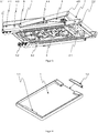
  • 4 das Grundelement im Einzelnen,
  • 5 einen Längsträger in einer dreidimensionalen Darstellung,
  • 6 das Seilzugsystem,
  • 7 den Riegelmechanismus für das hintere Rahmenelement,
  • 8 eine Explosionsdarstellung des Riegelmechanismus.
Show it:
  • 1 a handcart in operating condition,
  • 2 a handcart folded up in a side view,
  • 3 a handcart folded up in an oblique view from below,
  • 4th the basic element in detail,
  • 5 a side member in a three-dimensional representation,
  • 6th the cable system,
  • 7th the locking mechanism for the rear frame element,
  • 8th an exploded view of the locking mechanism.

Die 1 bis 3 zeigen einen erfindungsgemäßen Handwagen H mit einem darauf anordbaren nicht dargestellten Einkaufskorb. Gemäß den 2 und 3 ist der Handwagen H zusammengeklappt.the 1 until 3 show a handcart H according to the invention with a shopping basket (not shown) that can be arranged thereon. According to the 2 and 3 the handcart H is folded up.

Die Basis des Handwagens H bildet das Grundelement 1 auf das ein Einkaufskorb K gestellt werden kann. Ein derartiger Einkaufskorb ist vorzugsweise in Form eines handelsüblichen Klappkorbs ausgebildet, wobei diese Art der Klappkörbe standardmäßig über eine Kante verfügen. Diese Kante wird bei Montage des Klappkorbs auf der einen Seite unter ein, an dem Grundelement 1 vorgesehenen erstes Halteelement 1.1 geschoben. Gegenüberliegend ist ein zweites Halteelement 1.2 angeordnet, das herausnehmbar und/oder verstellbar ist und in Form einer Klemmverriegelung den Korb fixiert.The base of the handcart H forms the basic element 1 on which a shopping basket K can be placed. Such a shopping basket is preferably designed in the form of a commercially available folding basket, this type of folding baskets having an edge as standard. When the folding basket is installed, this edge is on one side under a, on the basic element 1 provided first holding element 1.1 pushed. Opposite is a second holding element 1.2 arranged that is removable and / or adjustable and fixes the basket in the form of a clamping lock.

Diese Art der Fixierung des Korbes ermöglicht auch ein Klappen des Einkaufskorbes während der Installation auf dem Grundelement 1, da die Fixierung außerhalb des Korbes erfolgt.This type of fixing of the basket also enables the shopping basket to be folded up during installation on the base element 1 , because the fixation takes place outside the basket.

Der Handwagen weist ein einklappbares Fahrwerk 2 mit einem ersten vorderen Rahmenelement 2.1 und einem zweiten hinteren Rahmenelement 2.2 mit daran angeordneten Rädern 3 auf. Das Fahrwerk 2 ist an einem ersten Längsträger 4, 4.1 und einem, über ein Grundelement 1 mit dem ersten Längsträger 4.1 verbundenen parallelen zweiten Längsträger 4.2 schwenkbar gelagert, wobei das erste Rahmenelement 2.1 mittels einer nicht dargestellten Achse in einer Bohrung 4.3 der Längsträger 4 gelagert ist. Das zweite Rahmenelement 2.2 ist in einer Führung 4.4 entlang der Längsträger 4 verschiebbar gelagert.The handcart has a retractable chassis 2 with a first front frame element 2.1 and a second rear frame member 2.2 with wheels arranged on it 3 on. The landing gear 2 is on a first side member 4th , 4.1 and one, about a primitive 1 with the first longitudinal member 4.1 connected parallel second longitudinal member 4.2 pivotally mounted, the first frame element 2.1 by means of an axis, not shown, in a bore 4.3 the side member 4th is stored. The second frame element 2.2 is on a tour 4.4 along the side members 4th movably mounted.

Die Längsträger 4 weisen einen ersten Endbereich und einen, dem ersten Endbereich gegenüberliegenden, zweiten Endbereich auf, wobei im ersten Endbereich je Längsträger 4 ein Rollelement 5 angeordnet ist, auf dem der Handwagen in den Kofferraum schiebbar ist. Das Rollelement 5 ist in Form einer Grundplatte 5.1 mit drei hintereinanderliegend angeordneten Rollen 5.2 ausgebildet, wobei die Rollen 5.2 je eine Rotationsachse aufweisen, die nach innen in Richtung des gegenüberliegenden Längsträgers 4 weist.The side members 4th have a first end area and a second end area opposite the first end area, with each longitudinal member in the first end area 4th a rolling element 5 is arranged on which the handcart can be pushed into the trunk. The rolling element 5 is in the form of a base plate 5.1 with three rollers arranged one behind the other 5.2 formed, the roles 5.2 each have an axis of rotation inward in the direction of the opposite side member 4th shows.

Das erste Rahmenelement 2.1 als Biegeprofil ausgebildet und an einer, mit den Längsträgern 4 verbundenen Achse in einer Bohrung 4.5 montiert. Die nicht dargestellte Achse erstreckt sich zwischen dem ersten und zweiten Längsträger 4.1, 4.2.The first frame element 2.1 designed as a bending profile and on one, with the longitudinal beams 4th connected axis in a hole 4.5 assembled. The axis, not shown, extends between the first and second side rails 4.1 , 4.2 .

Im zweiten Endbereich je Längsträger 4 ein Gelenkpunkt 4.6 für eine Abstützstrebe 6 des hinteren Rahmenelement 2.2 und eines Schiebegriffelements 7 mit einem daran ausgebildeten Griffbereich angeordnet, die im zusammengeklappten Zustand das Schiebergriffelement 7 auf im Wesentlichen die Höhe des Grundelements 1 klappbar ist. Das Schiebergriffelement 7 ist über eine zweite Abstützstrebe 8 mit dem Längsträger 4 im Gelenkpunkt 4.6 verbunden.In the second end area of each longitudinal beam 4th a pivot point 4.6 for a support strut 6th of the rear frame element 2.2 and a push handle element 7th arranged with a handle area formed thereon, which in the folded state, the slide handle element 7th to essentially the height of the base element 1 is foldable. The slide handle element 7th is via a second support strut 8th with the side member 4th in the hinge point 4.6 tied together.

Das hintere Rahmenelement 2.2 ist mittels Bolzen 9 in jeweils einer Führung 4.4 in dem ersten und zweiten Längsträger 4.1, 4.2 gelagert. An dem Bolzen 9 ist zudem das untere Ende des Schiebergriffelements 7 montiert, wobei im zusammenklappenden Zustand der Bolzen 9 entlang der Führung 4.4 nach vorn in Richtung des vorderen Endes der Längsträger gleitet und das hintere Rahmenelement 2.2 und das Schiebergriffelement 7 mitzieht.The rear frame element 2.2 is by means of bolts 9 in one tour each 4.4 in the first and second side rails 4.1 , 4.2 stored. On the bolt 9 is also the lower end of the slide handle element 7th mounted, with the bolt in the collapsed state 9 along the guide 4.4 slides forward towards the front end of the side member and the rear frame member 2.2 and the slide handle element 7th pulls along.

Bevorzugt ist die Führung 4.4 mit einer PTFE-Beschichtung versehen, um die Gleitfähigkeit zu erhöhen. Die Verbindung zwischen den Abstützstreben 6 und 8 bildet der Bolzen 9, auf die zur Aufnahme des Rahmens des Griffes eine Gleitbuchse genutzt wird. Zwischen dem Längsträger 4 und den Abstützstreben 6 und 8 des Rahmenelements 2.2 und des Schiebegriffelements 7 sind bevorzugt, wo benötigt, Gleitringe angeordnet.Leadership is preferred 4.4 provided with a PTFE coating to increase the sliding properties. The connection between the support struts 6th and 8th forms the bolt 9 , on which a sliding bushing is used to hold the frame of the handle. Between the side member 4th and the support struts 6th and 8th of the frame element 2.2 and the push handle element 7th sliding rings are preferred where required.

Gemäß den 2 und 3 sind für das Verstauen des Wagens bei Nichtgebrauch an der Unterseite des Grundelements 1 Haltemittel zum Verstauen der Räder 3 vorgesehen, wodurch sich der Platzbedarf bei der Lagerung weiter verringert. Die Räder 3 sind dafür von den Rahmenelementen 2.1, 2.2 abnehmbar ausgebildet und werden in einer Vertiefung innerhalb des Grundelements 1 angeordnet.According to the 2 and 3 are for stowing the trolley when not in use on the underside of the basic element 1 Holding means for stowing the wheels 3 provided, which further reduces the space required for storage. The wheels 3 are from the frame elements 2.1 , 2.2 detachable and are in a recess within the base element 1 arranged.

4 zeigt das Grundelement 1 im Einzelnen, wobei an dem Grundelement 1 das erste Halteelement 1.1 fest ausgebildet ist. Gegenüberliegend ist das zweites Halteelement 1.2 angeordnet, das herausnehmbar ist und in Form einer Klemmverriegelung den Korb fixiert. Durch eine derartige Fixierung des Korbes kann dieser auch bei erfolgter Montage auf dem Grundelement 1 zusammengeklappt werden. Der Handwagen findet insbesondere für übliche Klappkörbe Anwendung. 4th shows the basic element 1 in detail, with the basic element 1 the first holding element 1.1 is firmly formed. Opposite is the second holding element 1.2 arranged, which is removable and fixes the basket in the form of a clamping lock. By fixing the basket in this way, it can also be installed on the base element 1 be folded up. The handcart is used in particular for conventional folding baskets.

Die 5 zeigt einen der beiden Längsträger 4, wobei der erste und zweite Längsträger 4.1, 4.2 einen identischen gespiegelten Aufbau aufweisen.the 5 shows one of the two side members 4th , wherein the first and second side rails 4.1 , 4.2 have an identical mirrored structure.

Der Längsträger 4 weist an seinem vorderen Ende das Rollelement 5 auf, welches das Aufsetzen auf der Stoßstange und das Rollen im Kofferraum ermöglichen. Es besteht aus einer Grundplatte 5.1, die an den Längsträger 4 innenseitig an einer Aufnahme 4.7 angeschraubt ist und sich Drehen kann, wodurch auch schräge Kanten möglich sind.The longitudinal beam 4th has the rolling element at its front end 5 which allow it to be placed on the bumper and rolling in the trunk. It consists of a base plate 5.1 attached to the side member 4th inside on a recording 4.7 is screwed on and can rotate, which means that inclined edges are also possible.

An der Grundplatte 5.1 können beliebig viele, im vorliegenden Fall drei Rollen 5.2 befestigt sein. Ein für ein Rad benötigtes Set besteht dabei aus einer Schraube die als Achse dient, eine Abstandselement und einer Mutter. Zwischen dem Abstandselement und der Mutter befindet sich die Rolle 5.2, welche bevorzugt durch zwei Kugellager gelagert wird. Zur Verschleißminimierung der Kugellager befindet sich zwischen diesen Beiden auf der Schaube noch ein Abstandselement.At the base plate 5.1 can have any number, in this case three roles 5.2 be attached. A set required for a wheel consists of a screw that serves as an axle, a spacer element and a nut. The roller is located between the spacer element and the nut 5.2 , which is preferably supported by two ball bearings. To minimize wear on the ball bearings, there is a spacer between these two on the screw.

Entlang des Längsträgers 4 erstreckt sich die Führung 4.4, in der der Bolzen 9 verschiebbar angeordnet ist. Zwischen der Führung 4.4 und dem Rollelement 5 ist die Bohrung 4.3 angeordnet, mittels derer die nicht dargestellte Achse des vorderen Rahmenelements 2.1 gelagert ist.Along the side member 4th extends the leadership 4.4 in which the bolt 9 is arranged displaceably. Between the tour 4.4 and the rolling element 5 is the hole 4.3 arranged, by means of which the axis, not shown, of the front frame element 2.1 is stored.

In dem Längsträger 4 ist ein Seilzugsystem 10 für die Entriegelung des vorderen Rahmenelements 2.1 angeordnet. Das Seilzugsystem 10 ist in 6 herausgelöst dargestelltIn the side member 4th is a cable system 10 for unlocking the front frame element 2.1 arranged. The cable system 10 is in 6th shown detached

In der 6 ist das Seilzugsystem 10 für die Verriegelung des ersten Rahmenelements dargestellt.In the 6th is the cable system 10 shown for locking the first frame element.

Zur Sicherstellung, dass sich das Rahmenelement 2.1 vorne während der Benutzung nicht ungewollt einklappt, befindet sich hier ein Mechanismus, der sowohl Rahmenelement 2.1 im Nutzungs- als auch im Lagerungszustand fixiert.To ensure that the frame element 2.1 does not unintentionally fold in front during use, there is a mechanism here that serves as both a frame element 2.1 Fixed in use as well as in storage condition.

Im Längsträger 4 befinden sich hierfür entsprechende Ausschnitte, wobei der Mechanismus bevorzugt in diese genietet wird.In the side member 4th there are corresponding cutouts for this purpose, whereby the mechanism is preferably riveted into these.

Hauptbestandteil ist ein Bowdenzug 10.1, der die Bewegung aus einem nicht dargestellten Griff zum Mechanismus überträgt. Dieser ist mit Klammern 10.2 an einem Träger 10.3 fixiert. Der Träger 10.3 beinhaltet die Aufnahme für die Achse des vorderen Rahmenelements 2.1 für die vorderen Räder, einen Anschlag für dieses und auf der gegenüberliegenden Seite des Anschlags eine Führung für die Verriegelung. Die Verriegelung, bestehen aus einem Blech 10.4, Federn 10.5 und einer Achse 10.6, fixiert durch eine Mutter 10.7, wird durch die Federn 10.5 dauerhaft geschlossen und durch Zug an dem Bowdenzug 10.1 freigegeben.The main component is a Bowden cable 10.1 , which transmits the movement from a handle, not shown, to the mechanism. This one is with brackets 10.2 on a carrier 10.3 fixed. The carrier 10.3 contains the receptacle for the axis of the front frame element 2.1 for the front wheels, a stop for this and on the opposite side of the stop a guide for the lock. The interlocks consist of a sheet metal 10.4 , Feathers 10.5 and an axis 10.6 , fixed by a nut 10.7 , is through the springs 10.5 permanently closed and by pulling the bowden cable 10.1 Approved.

Dieses Teil ist symmetrisch auch auf dem anderen Hauptträger zu finden. Die Bowdenzüge 10.1 werden am Zuggriff zusammengeführt, wodurch mit einem Griff beide Seiten entriegelt werden können.This part can also be found symmetrically on the other main beam. The bowden cables 10.1 are brought together at the pull handle, whereby both sides can be unlocked with one handle.

Die, in dem hinteren Bereich des Längsträgers 4 angeordnete Verriegelung des zweiten Rahmenelements 2.2 ist in der 7 und als Explosionszeichnung in 8 dargestellt. Zum Verhindern des Einklappens des hinteren Rahmenelements 2.2 während der Benutzung befindet sich zum einen in der Führung 4.4 im Längsträger 4 eine Ausbuchtung 4.8 nach oben, in die sich der Bolzen 9 drückt und zum anderen ein Riegelmechanismus 11. Dieser Riegelmechanismus 11 ist mit einem Halter 11.1 in dem Längsträger 4 gelagert und besteht aus einer inneren Achse 11.2 und einem darauf geschobenem Rohr 11.3. An diesem Rohr 11.3 befindet sich der Riegel 11.4, welcher mittels einer Madenschraube 11.5 befestigt ist. Auf der inneren Achse 11.2 befindet sich eine Feder 11.6 zwischen dem Halter 11.1 und dem Rohr 11.3.The one in the back of the side member 4th arranged locking of the second frame element 2.2 is in the 7th and as an exploded view in 8th shown. To prevent the rear frame element from collapsing 2.2 during use there is on the one hand in the guide 4.4 in the side member 4th a bulge 4.8 up into which the bolt is located 9 presses and on the other hand a locking mechanism 11 . This locking mechanism 11 is with a holder 11.1 in the side member 4th stored and consists of an inner axle 11.2 and a pipe pushed on it 11.3 . On this pipe 11.3 is the latch 11.4 , which by means of a grub screw 11.5 is attached. On the inner axis 11.2 there is a spring 11.6 between the holder 11.1 and the pipe 11.3 .

Auf der anderen Seite ist ein Hebel 11.7 mit einer Schraube 11.8 aufgeschraubt. Auf dieser Seite ist die Lagerung durch die Endkappe realisiert, die innen mit Nuten 11.9 in zwei Stellungen versehen ist. auf dem Rohr 11.3 befindet sich das Gegenstück 11.10, welches durch die Feder 11.6 in der vordefinierten Stellung fixiert wird.On the other side is a lever 11.7 with a screw 11.8 unscrewed. On this side, the storage is realized by the end cap, which has grooves on the inside 11.9 is provided in two positions. on the pipe 11.3 is the counterpart 11.10 which by the pen 11.6 is fixed in the predefined position.

BezugszeichenlisteList of reference symbols

11
GrundelementBasic element
1.11.1
erstes Halteelementfirst holding element
1.21.2
zweites Halteelementsecond holding element
22
RahmenelementFrame element
2.12.1
Erstes vorderes RahmenelementFirst front frame element
2.22.2
Zweites hinteres RahmenelementSecond rear frame element
33
Räderbikes
44th
LängsträgerSide member
4.14.1
Erster LängsträgerFirst side member
4.24.2
Zweiter LängsträgerSecond side member
4.34.3
Bohrungdrilling
4.44.4
Führungguide
4.54.5
Bohrungdrilling
4.64.6
GelenkpunktPivot point
4.74.7
Aufnahmerecording
4.84.8
Ausbuchtungbulge
55
RollelementRolling element
5.15.1
GrundplatteBase plate
5.25.2
Rollerole
66th
AbstützstrebeSupport strut
77th
SchiebegriffelementPush handle element
88th
AbstützstrebeSupport strut
99
Bolzenbolt
1010
SeilzugsystemCable system
10.110.1
BowdenzugBowden cable
10.210.2
KlammerBracket
10.310.3
Trägercarrier
10.410.4
Blechsheet
10.510.5
Federfeather
10.610.6
Achseaxis
10.710.7
Muttermother
1111
RiegelmechanismusLatch mechanism
11.111.1
Halterholder
11.211.2
Innere AchseInner axis
11.311.3
Rohrpipe
11.411.4
Riegelbars
11.511.5
MadenschraubeGrub screw
11.611.6
Federfeather
11.711.7
Hebellever
11.811.8
Schraubescrew
11.911.9
NutGroove
11.1011.10
GegenstückCounterpart

Claims (10)

Handwagen zum direkten Verladen in ein Kraftfahrzeug, insbesondere in den Laderaum eines Kraftfahrzeugs, wobei der Handwagen ein einklappbares Fahrwerk mit einem ersten Rahmenelement (2.1) und einem zweiten Rahmenelement (2.2) mit daran angeordneten Rädern (3) aufweist, das an einem ersten Längsträger (4, 4.1) und einem, über ein Grundelement (1) mit dem ersten Längsträger (4.1) verbundenen parallelen zweiten Längsträger (4, 4.2) schwenkbar gelagert ist, wobei das erste Rahmenelement (2.1) mittels einer Achse in einer Bohrung (4.5) der Längsträger (4) und das zweite Rahmenelement (2.2) in einer Führung (4.4) entlang der Längsträger (4) verschiebbar gelagert ist und wobei die Längsträger (4) je einen ersten Endbereich und einen, dem ersten Endbereich gegenüberliegenden, zweiten Endbereich aufweisen, wobei im ersten Endbereich je Längsträger (4) ein Rollelement (5) angeordnet ist, auf dem der Handwagen in den Kofferraum schiebbar ist und im zweiten Endbereich je Längsträger (4) ein Gelenkpunkt (4.6) für eine Abstützstrebe (6) des hinteren Rahmenelements (2.2) und ein Abstützelement (8) eines an dem Bolzen (9) montierten Schiebegriffelements (7) angeordnet ist derart, dass im zusammengeklappten Zustand das Schiebergriffelement (7) auf im Wesentlichen die Höhe des Grundelements (1) klappbar ist.Hand trolley for direct loading into a motor vehicle, in particular into the cargo space of a motor vehicle, the hand trolley having a retractable chassis with a first frame element (2.1) and a second frame element (2.2) with wheels (3) arranged thereon, which is attached to a first longitudinal member ( 4, 4.1) and a, via a base element (1) with the first longitudinal beam (4.1) connected parallel second longitudinal beam (4, 4.2) is pivotably mounted, the first frame element (2.1) by means of an axis in a bore (4.5) of the The longitudinal beam (4) and the second frame element (2.2) are slidably mounted in a guide (4.4) along the longitudinal beam (4) and the longitudinal beams (4) each have a first end region and a second end region opposite the first end region, wherein a rolling element (5) on which the handcart can be pushed into the trunk is arranged in the first end area of each longitudinal beam (4) and a gel for each longitudinal beam (4) in the second end area kpunkt (4.6) for a support strut (6) of the rear frame element (2.2) and a support element (8) of a push handle element (7) mounted on the bolt (9) is arranged such that in the folded state the slider handle element (7) is essentially on the height of the base element (1) is foldable. Handwagen nach Anspruch 1, dadurch gekennzeichnet, dass das Rollelement in Form einer an dem Längsträger drehbar gelagerten Grundplatte mit wenigstens zwei hintereinanderliegend angeordneten Rollen ausgebildet ist, wobei die Rollen je eine Rotationsachse aufweisen, die nach innen in Richtung des gegenüberliegenden Längsträgers weist.Handcart after Claim 1 , characterized in that the rolling element is designed in the form of a base plate rotatably mounted on the longitudinal beam with at least two rollers arranged one behind the other, the rollers each having an axis of rotation which points inward towards the opposite longitudinal beam. Handwagen nach Anspruch 1 oder 2, dadurch gekennzeichnet, dass das Grundelement (1) eine umfangsseitige Führung für einen Einkaufskorb aufweist und dass das Grundelement (1) ein erstes Halteelement an einer ersten Seite und ein, dem ersten Halteelement gegenüberliegend zweites Halteelement aufweist, wobei das zweite Halteelement herausnehmbar und/oder verstellbar ist und dass eine umlaufende Kante eines Einkaufskorbs unter die Halteelemente schiebbar ist derart, dass eine Fixierung des Einkaufskorbs auf dem Grundelement (1) erfolgt.Handcart after Claim 1 or 2 , characterized in that the base element (1) has a circumferential guide for a shopping basket and that the base element (1) has a first holding element on a first side and a second holding element opposite the first holding element, the second holding element being removable and / or is adjustable and that a circumferential edge of a shopping basket can be pushed under the holding elements in such a way that the shopping basket is fixed on the base element (1). Handwagen nach einem der Ansprüche 1 bis 3, dadurch gekennzeichnet, dass das vordere Rahmenelement (2.1) mittels eines Seilzugsystems (10) aus einer festen Position entriegelbar ist.Handcart for one of the Claims 1 until 3 , characterized in that the front frame element (2.1) can be unlocked from a fixed position by means of a cable pull system (10). Handwagen nach einem der Ansprüche 1 bis 4, dadurch gekennzeichnet, dass das hintere Rahmenelement an dem ersten Längsträger mittels eines ersten Bolzens und an dem zweiten Längsträger mittels eines zweiten Bolzens in der jeweiligen Führung gelagert ist, wobei die Führung eine Ausbuchtung nach oben aufweist, in die sich die Bolzen in der ausgeklappten Position drücken.Handcart for one of the Claims 1 until 4th , characterized in that the rear frame element is mounted on the first longitudinal member by means of a first bolt and on the second longitudinal member by means of a second bolt in the respective guide, the guide having an upward bulge into which the bolts are in the unfolded position to press. Handwagen nach Anspruch 5, dadurch gekennzeichnet, dass mittels der Bolzen das hintere Rahmenelement und das Schiebegriffelement koaxial gelagert und miteinander verbunden sind.Handcart after Claim 5 , characterized in that the rear frame element and the push handle element are mounted coaxially and connected to one another by means of the bolts. Handwagen nach einem der Ansprüche 1 bis 6, dass das hintere Rahmenelement mittels eines drehbaren Riegels in der Führung gegen ein unbeabsichtigtes Einklappen gesichert ist.Handcart for one of the Claims 1 until 6th that the rear frame element is secured against unintentional collapse by means of a rotatable bolt in the guide. Handwagen nach Anspruch 7, dadurch gekennzeichnet, dass der Riegel über ein Rohr mit einem Hebel verbunden ist, der mittels Nuten in einer ersten und zweiten Position fixierbar ist, wobei die erste Position des Riegels das hintere Rahmenelement gegen ein Einklappen fixiert und die zweite Position die Führung frei gibt.Handcart after Claim 7 , characterized in that the bolt is connected via a tube to a lever which can be fixed in a first and second position by means of grooves, the first position of the bolt fixing the rear frame element against folding in and the second position releasing the guide. Handwagen nach einem der Ansprüche 1 bis 8, dadurch gekennzeichnet, dass das vordere Rahmenelement in Form eines Biegeprofils ausgebildet ist.Handcart for one of the Claims 1 until 8th , characterized in that the front frame element is designed in the form of a bending profile. Handwagen nach einem der Ansprüche 1 bis 9, dadurch gekennzeichnet, dass die Räder (3) abnehmbar sind.Handcart for one of the Claims 1 until 9 , characterized in that the wheels (3) are removable.
DE102021110421.1A 2021-04-23 2021-04-23 Hand trolley for direct loading into a motor vehicle Active DE102021110421B3 (en)

Priority Applications (2)

Application Number Priority Date Filing Date Title
DE102021110421.1A DE102021110421B3 (en) 2021-04-23 2021-04-23 Hand trolley for direct loading into a motor vehicle
EP22162409.1A EP4079601A1 (en) 2021-04-23 2022-03-16 Trolley for direct loading into a motor vehicle

Applications Claiming Priority (1)

Application Number Priority Date Filing Date Title
DE102021110421.1A DE102021110421B3 (en) 2021-04-23 2021-04-23 Hand trolley for direct loading into a motor vehicle

Publications (1)

Publication Number Publication Date
DE102021110421B3 true DE102021110421B3 (en) 2021-09-09

Family

ID=77388973

Family Applications (1)

Application Number Title Priority Date Filing Date
DE102021110421.1A Active DE102021110421B3 (en) 2021-04-23 2021-04-23 Hand trolley for direct loading into a motor vehicle

Country Status (2)

Country Link
EP (1) EP4079601A1 (en)
DE (1) DE102021110421B3 (en)

Citations (7)

* Cited by examiner, † Cited by third party
Publication number Priority date Publication date Assignee Title
FR2775645B1 (en) 1998-03-06 2000-06-02 Patrice Vasseur MECHANISM FOR AUTOMATIC FOLDABLE TROLLEY
FR2850623A1 (en) 2003-02-03 2004-08-06 Alain Navelier Basket trolley for shopping in supermarket, has four supports that is fixed at front and back side of basket for maintaining lock and base in position, where base rotates around axis after unlocking it
DE102008031541A1 (en) 2008-07-03 2010-01-07 Strauss, Dietmar Trolley i.e. shopping trolley, for use by consumer e.g. during transportation of article i.e. goods, in supermarket, has transportation basket i.e. folding box, that is fixed on foldable chassis in foldable and detachable manner
DE202010014136U1 (en) 2010-10-09 2011-02-10 Mink, Carmen Shopping venture
DE102010022452A1 (en) 2010-06-02 2011-12-08 Tanja Dück Handcart i.e. shopping trolley, for installation at loading edge of e.g. loading area of e.g. motor car, has chassis element movable in back and forth between transport position and procedure position opposite to container
FR2971220A1 (en) 2011-02-09 2012-08-10 Peugeot Citroen Automobiles Sa Load transportation system for e.g. transporting purchased goods in shop, has deploying and folding units for permitting deployment of system from folded position to deployed position by moving load support plate along axis
FR2987592B1 (en) 2012-03-01 2014-04-18 Peugeot Citroen Automobiles Sa TRANSFORMABLE TRANSPORT TROLLEY AT HEIGHT ADAPTABLE BY RABBING OF LEGS AND WHEELS AND ACTUATION OF MEANS OF ADAPTATION

Family Cites Families (2)

* Cited by examiner, † Cited by third party
Publication number Priority date Publication date Assignee Title
US8172256B2 (en) * 2009-03-16 2012-05-08 Ami Amos Fine Cart
US9126610B1 (en) * 2014-05-16 2015-09-08 Sagi Abiri Collapsible shopping cart apparatus

Patent Citations (7)

* Cited by examiner, † Cited by third party
Publication number Priority date Publication date Assignee Title
FR2775645B1 (en) 1998-03-06 2000-06-02 Patrice Vasseur MECHANISM FOR AUTOMATIC FOLDABLE TROLLEY
FR2850623A1 (en) 2003-02-03 2004-08-06 Alain Navelier Basket trolley for shopping in supermarket, has four supports that is fixed at front and back side of basket for maintaining lock and base in position, where base rotates around axis after unlocking it
DE102008031541A1 (en) 2008-07-03 2010-01-07 Strauss, Dietmar Trolley i.e. shopping trolley, for use by consumer e.g. during transportation of article i.e. goods, in supermarket, has transportation basket i.e. folding box, that is fixed on foldable chassis in foldable and detachable manner
DE102010022452A1 (en) 2010-06-02 2011-12-08 Tanja Dück Handcart i.e. shopping trolley, for installation at loading edge of e.g. loading area of e.g. motor car, has chassis element movable in back and forth between transport position and procedure position opposite to container
DE202010014136U1 (en) 2010-10-09 2011-02-10 Mink, Carmen Shopping venture
FR2971220A1 (en) 2011-02-09 2012-08-10 Peugeot Citroen Automobiles Sa Load transportation system for e.g. transporting purchased goods in shop, has deploying and folding units for permitting deployment of system from folded position to deployed position by moving load support plate along axis
FR2987592B1 (en) 2012-03-01 2014-04-18 Peugeot Citroen Automobiles Sa TRANSFORMABLE TRANSPORT TROLLEY AT HEIGHT ADAPTABLE BY RABBING OF LEGS AND WHEELS AND ACTUATION OF MEANS OF ADAPTATION

Also Published As

Publication number Publication date
EP4079601A1 (en) 2022-10-26

Similar Documents

Publication Publication Date Title
DE3423528C2 (en) Dolly
DE112008003162B4 (en) Transport system, especially with movable pallets
EP3103712B1 (en) Foldable scooter
DE19534974A1 (en) Collapsible cart
DE10204478A1 (en) Multi-function mobile device has handle and front and rear part with wheels and convertible between scooter position with step board and a trolley and caddy position with operating handle
DE3705187A1 (en) GOLF CAR
DE3007578A1 (en) LOAD CARRIERS
AT518514A2 (en) Cart
DE102017001747A1 (en) Collapsible shopping and transport trolley with receiving device for transporting goods and goods
DE102018110024B4 (en) Collapsible wheelbarrow for transporting stacked goods
DE102021110421B3 (en) Hand trolley for direct loading into a motor vehicle
DE102014002237B4 (en) Collapsible wheelbarrow
DE102023103476B4 (en) Foldable transport device for bicycles
EP4031435B1 (en) Transport trolley and method for transforming a transport trolley
DE102021118636B4 (en) Device for carrying loads
EP1829763A2 (en) Device for transporting loads
DE202021102196U1 (en) Hand truck for loading directly into a motor vehicle
EP3943365A2 (en) Running gear for a trolley and trolley
DE202017100729U1 (en) Collapsible transport trolley with transport crate and collapsible transport crate for a transport trolley
WO1998056640A1 (en) Skibob
DE3420422A1 (en) Tailgate
DE102021125388B4 (en) Folding bike
DE2743214A1 (en) LIFT TRUCK WITH CLIMBING DEVICE
DE102022107154B9 (en) Transport device for overcoming a step-like obstacle
DE3419980C1 (en) Roof rack for vehicles

Legal Events

Date Code Title Description
R012 Request for examination validly filed
R016 Response to examination communication
R018 Grant decision by examination section/examining division
R020 Patent grant now final