DE102021105451B4 - SRAM STRUCTURE WITH ASYMMETRIC INTERCONNECTION - Google Patents

SRAM STRUCTURE WITH ASYMMETRIC INTERCONNECTION Download PDF

Info

Publication number
DE102021105451B4
DE102021105451B4 DE102021105451.6A DE102021105451A DE102021105451B4 DE 102021105451 B4 DE102021105451 B4 DE 102021105451B4 DE 102021105451 A DE102021105451 A DE 102021105451A DE 102021105451 B4 DE102021105451 B4 DE 102021105451B4
Authority
DE
Germany
Prior art keywords
substrate
power supply
pass gate
cell
sram
Prior art date
Legal status (The legal status is an assumption and is not a legal conclusion. Google has not performed a legal analysis and makes no representation as to the accuracy of the status listed.)
Active
Application number
DE102021105451.6A
Other languages
German (de)
Other versions
DE102021105451A1 (en
Inventor
Yi-Hsun CHIU
Chia-En HUANG
Current Assignee (The listed assignees may be inaccurate. Google has not performed a legal analysis and makes no representation or warranty as to the accuracy of the list.)
Taiwan Semiconductor Manufacturing Co TSMC Ltd
Original Assignee
Taiwan Semiconductor Manufacturing Co TSMC Ltd
Priority date (The priority date is an assumption and is not a legal conclusion. Google has not performed a legal analysis and makes no representation as to the accuracy of the date listed.)
Filing date
Publication date
Application filed by Taiwan Semiconductor Manufacturing Co TSMC Ltd filed Critical Taiwan Semiconductor Manufacturing Co TSMC Ltd
Publication of DE102021105451A1 publication Critical patent/DE102021105451A1/en
Application granted granted Critical
Publication of DE102021105451B4 publication Critical patent/DE102021105451B4/en
Active legal-status Critical Current
Anticipated expiration legal-status Critical

Links

Images

Classifications

    • GPHYSICS
    • G11INFORMATION STORAGE
    • G11CSTATIC STORES
    • G11C11/00Digital stores characterised by the use of particular electric or magnetic storage elements; Storage elements therefor
    • G11C11/21Digital stores characterised by the use of particular electric or magnetic storage elements; Storage elements therefor using electric elements
    • G11C11/34Digital stores characterised by the use of particular electric or magnetic storage elements; Storage elements therefor using electric elements using semiconductor devices
    • G11C11/40Digital stores characterised by the use of particular electric or magnetic storage elements; Storage elements therefor using electric elements using semiconductor devices using transistors
    • G11C11/41Digital stores characterised by the use of particular electric or magnetic storage elements; Storage elements therefor using electric elements using semiconductor devices using transistors forming static cells with positive feedback, i.e. cells not needing refreshing or charge regeneration, e.g. bistable multivibrator or Schmitt trigger
    • G11C11/412Digital stores characterised by the use of particular electric or magnetic storage elements; Storage elements therefor using electric elements using semiconductor devices using transistors forming static cells with positive feedback, i.e. cells not needing refreshing or charge regeneration, e.g. bistable multivibrator or Schmitt trigger using field-effect transistors only
    • HELECTRICITY
    • H10SEMICONDUCTOR DEVICES; ELECTRIC SOLID-STATE DEVICES NOT OTHERWISE PROVIDED FOR
    • H10BELECTRONIC MEMORY DEVICES
    • H10B10/00Static random access memory [SRAM] devices
    • H10B10/12Static random access memory [SRAM] devices comprising a MOSFET load element
    • HELECTRICITY
    • H10SEMICONDUCTOR DEVICES; ELECTRIC SOLID-STATE DEVICES NOT OTHERWISE PROVIDED FOR
    • H10DINORGANIC ELECTRIC SEMICONDUCTOR DEVICES
    • H10D89/00Aspects of integrated devices not covered by groups H10D84/00 - H10D88/00
    • H10D89/10Integrated device layouts
    • GPHYSICS
    • G11INFORMATION STORAGE
    • G11CSTATIC STORES
    • G11C11/00Digital stores characterised by the use of particular electric or magnetic storage elements; Storage elements therefor
    • G11C11/21Digital stores characterised by the use of particular electric or magnetic storage elements; Storage elements therefor using electric elements
    • G11C11/34Digital stores characterised by the use of particular electric or magnetic storage elements; Storage elements therefor using electric elements using semiconductor devices
    • G11C11/40Digital stores characterised by the use of particular electric or magnetic storage elements; Storage elements therefor using electric elements using semiconductor devices using transistors
    • G11C11/41Digital stores characterised by the use of particular electric or magnetic storage elements; Storage elements therefor using electric elements using semiconductor devices using transistors forming static cells with positive feedback, i.e. cells not needing refreshing or charge regeneration, e.g. bistable multivibrator or Schmitt trigger
    • G11C11/413Auxiliary circuits, e.g. for addressing, decoding, driving, writing, sensing, timing or power reduction
    • G11C11/417Auxiliary circuits, e.g. for addressing, decoding, driving, writing, sensing, timing or power reduction for memory cells of the field-effect type
    • HELECTRICITY
    • H10SEMICONDUCTOR DEVICES; ELECTRIC SOLID-STATE DEVICES NOT OTHERWISE PROVIDED FOR
    • H10BELECTRONIC MEMORY DEVICES
    • H10B99/00Subject matter not provided for in other groups of this subclass
    • HELECTRICITY
    • H10SEMICONDUCTOR DEVICES; ELECTRIC SOLID-STATE DEVICES NOT OTHERWISE PROVIDED FOR
    • H10WGENERIC PACKAGES, INTERCONNECTIONS, CONNECTORS OR OTHER CONSTRUCTIONAL DETAILS OF DEVICES COVERED BY CLASS H10
    • H10W20/00Interconnections in chips, wafers or substrates
    • H10W20/40Interconnections external to wafers or substrates, e.g. back-end-of-line [BEOL] metallisations or vias connecting to gate electrodes
    • H10W20/41Interconnections external to wafers or substrates, e.g. back-end-of-line [BEOL] metallisations or vias connecting to gate electrodes characterised by their conductive parts
    • H10W20/427Power or ground buses
    • HELECTRICITY
    • H10SEMICONDUCTOR DEVICES; ELECTRIC SOLID-STATE DEVICES NOT OTHERWISE PROVIDED FOR
    • H10DINORGANIC ELECTRIC SEMICONDUCTOR DEVICES
    • H10D30/00Field-effect transistors [FET]
    • H10D30/60Insulated-gate field-effect transistors [IGFET]
    • H10D30/62Fin field-effect transistors [FinFET]

Landscapes

  • Engineering & Computer Science (AREA)
  • Microelectronics & Electronic Packaging (AREA)
  • Computer Hardware Design (AREA)
  • Semiconductor Memories (AREA)
  • General Engineering & Computer Science (AREA)
  • Die Bonding (AREA)
  • Superconductors And Manufacturing Methods Therefor (AREA)
  • Photovoltaic Devices (AREA)

Abstract

Halbleiterstruktur aufweisend:
ein Substrat (602, 702) aufweisend eine Vorderseite und eine Rückseite;
eine SRAM-Schaltung aufweisend SRAM-Bitzellen (104, 104A, 104B), die auf der Vorderseite des Substrats (602, 702) gebildet sind, wobei eine erste SRAM-Bitzelle (104A) der SRAM-Bitzellen (104, 104A, 104B) zwei kreuzgekoppelte Inverter und ein erstes Pass-Gate (PG-1) und ein zweites Pass-Gate (PG-2) aufweist, die mit den zwei Invertern gekoppelt sind;
eine erste Bitleitung (BL, BLB), die auf der Vorderseite des Substrats (602, 702) angeordnet ist und mit dem ersten Pass-Gate (PG-1) verbunden ist; und
eine zweite Bitleitung (BL, BLB), die auf der Rückseite des Substrats (602, 702) angeordnet ist und mit dem zweiten Pass-Gate (PG-2) verbunden ist;
eine erste Stromversorgungsleitung (Vdd, Vss), die auf der Vorderseite des Substrats (602, 702) angeordnet ist und mit einem Feldeffekttransistor, FET, des ersten Typs der zwei Inverter verbunden ist; und
eine zweite Stromversorgungsleitung (Vdd, Vss), die auf der Rückseite des Substrats (602, 702) angeordnet ist und mit einem FET des zweiten Typs der zwei Inverter verbunden ist;
wobei eine dritte Stromversorgungsleitung (Vdd, Vss) auf der Vorderseite des Substrats (602, 702) angeordnet ist und mit einem anderen FET des zweiten Typs der zwei Inverter verbunden ist, und wobei die dritte Stromversorgungsleitung (Vss) eine niedrigere Stromversorgungsleitung Vss ist.
Semiconductor structure having:
a substrate (602, 702) having a front side and a back side;
an SRAM circuit comprising SRAM bit cells (104, 104A, 104B) formed on the front side of the substrate (602, 702), wherein a first SRAM bit cell (104A) of the SRAM bit cells (104, 104A, 104B) has two cross-coupled inverters and a first pass gate (PG-1) and a second pass gate (PG-2) coupled to the two inverters;
a first bit line (BL, BLB) arranged on the front side of the substrate (602, 702) and connected to the first pass gate (PG-1); and
a second bit line (BL, BLB) arranged on the back side of the substrate (602, 702) and connected to the second pass gate (PG-2);
a first power supply line (Vdd, Vss) arranged on the front side of the substrate (602, 702) and connected to a field effect transistor, FET, of the first type of the two inverters; and
a second power supply line (Vdd, Vss) arranged on the back side of the substrate (602, 702) and connected to a second type FET of the two inverters;
wherein a third power supply line (Vdd, Vss) is arranged on the front side of the substrate (602, 702) and is connected to another FET of the second type of the two inverters, and wherein the third power supply line (Vss) is a lower power supply line Vss.

Description

HINTERGRUNDBACKGROUND

Eine integrierte Schaltung umfasst verschiedene Schaltungen mit jeweiligen Funktionen wie beispielsweise eine Speicherschaltung mit mehreren Speicher-Bitzellen zur Speicherung von Informationen. Die Speicherschaltung umfasst nichtflüchtige oder flüchtige Vorrichtungen. Zu den flüchtigen Vorrichtungen zählen beispielsweise SRAM-Vorrichtungen (Static Random Access Memory). Dreidimensionale Transistoren mit finnenartigen aktiven Bereichen werden oft für eine verbesserte Vorrichtungsleistung gewünscht. Diese dreidimensionalen Feldeffekttransistoren (FETs), die auf aktiven Bereichen mit Finnen gebildet werden, werden auch als FinFETs bezeichnet. Andere dreidimensionale Feldeffekttransistoren umfassen Gate-All-Around-FETs. Diese FETs benötigen eine geringe Finnenbreite für eine kurze Kanalsteuerung, was zu kleineren Source/Drain-Bereichen als bei planaren FETs führt. Dies reduziert Spielräume bei Ausrichtung und verursacht Probleme bei immer kleiner werdenden Vorrichtungsabständen und immer steigender Packungsdichte. Wenn die Metall-Interconnect (Verbindung) zur Verbesserung der Schaltungsdichte weiter zu immer kleineren Merkmalsgrößen verkleinert werden, werden die bestehenden Interconnect-Strukturanordnungen in engeren Metallschichten mit verschiedenen Problemen konfrontiert. Beispielsweise gibt es Probleme bei der Metallfüllung, da Metallleitungen oder Stopfen zwecks der Zuverlässigkeit eine Diffusionssperrmetallschicht erfordern und die Barriereschicht die Größe der Metallleitungen und Metallstopfen weiter reduziert. Diese Sperrmetallschichten beeinflussen die Fähigkeit zur Grabenfüllung und führen daher zu einer Verschlechterung des Metallwiderstands oder sogar zu noch schlimmeren Problemen, wie beispielsweise einer Öffnung von Durchkontaktierungen oder einer Elektromigration (EM). Weitere Probleme bei der Verkleinerung der Vorrichtungsgrößen sind ein erhöhter Routing-Widerstand, erhöhte parasitäre Kapazitäten, Kurzschlüsse, Leckströme, Spielräume bei Ausrichtung, Layout-Flexibilität und Packungsdichte. Daher besteht ein Bedarf an einer Struktur und einem Verfahren zur Herstellung von SRAM-Strukturen, um diese Probleme mit verbesserter Schaltungsleistung und Zuverlässigkeit sowie erhöhter Packungsdichte zu lösen.An integrated circuit includes various circuits with respective functions, such as a memory circuit with multiple memory bit cells for storing information. The memory circuit includes non-volatile or volatile devices. Examples of volatile devices include static random access memory (SRAM) devices. Three-dimensional transistors with fin-like active areas are often desired for improved device performance. These three-dimensional field-effect transistors (FETs) formed on active areas with fins are also called FinFETs. Other three-dimensional field-effect transistors include gate-all-around FETs. These FETs require a small fin width for short channel control, resulting in smaller source/drain areas than planar FETs. This reduces alignment margins and causes problems as device pitches become smaller and packing density increases. As metal interconnects continue to shrink to smaller feature sizes to improve circuit density, the existing interconnect structure arrangements in tighter metal layers face various problems. For example, there are metal filling issues because metal lines or plugs require a diffusion barrier metal layer for reliability and the barrier layer further reduces the size of the metal lines and metal plugs. These barrier metal layers affect the trench filling ability and therefore lead to degradation of metal resistance or even worse problems such as via opening or electromigration (EM). Other issues with shrinking device sizes include increased routing resistance, increased parasitic capacitances, short circuits, leakage currents, alignment margins, layout flexibility and packing density. Therefore, there is a need for a structure and method for fabricating SRAM structures to solve these issues with improved circuit performance and reliability as well as increased packing density.

US 2018/0219015 A1 offenbart Techniken und Mechanismen zum Austausch von Signalen mit einem oder mehreren Transistoren an einer Vorderseite eines Halbleitersubstrats. US 2007/0296002 A1 offenbart eine Halbleiterstruktur, die ein Halbleitersubstrat mit einer ersten Oberfläche und einer zweiten Oberfläche gegenüber der ersten Oberfläche. US 9,257,439 B2 offenbart eine eingebettete FinFET-SRAM-Struktur und Verfahren zu deren Herstellung. US 2018/0219015 A1 discloses techniques and mechanisms for exchanging signals with one or more transistors on a front side of a semiconductor substrate. US 2007/0296002 A1 discloses a semiconductor structure comprising a semiconductor substrate having a first surface and a second surface opposite the first surface. US9,257,439 B2 discloses an embedded FinFET SRAM structure and methods for fabricating the same.

Die Erfindung wird durch die unabhängigen Patentansprüche definiert.The invention is defined by the independent patent claims.

KURZBESCHREIBUNG DER ZEICHNUNGENBRIEF DESCRIPTION OF THE DRAWINGS

Aspekte der vorliegenden Offenbarung lassen sich am besten anhand der folgenden ausführlichen Beschreibung in Verbindung mit den begleitfähigen Zeichnungen verstehen. Es ist zu verstehen, dass die verschiedenen Merkmale gemäß der branchenüblichen Praxis nicht maßstabsgetreu dargestellt sind. Tatsächlich können die Abmessungen der verschiedenen Merkmale zugunsten einer klaren Diskussion beliebig vergrößert oder verkleinert sein. Die verschiedenen Zeichnungen und die jeweilige Beschreibung werden in einer Power Point-Datei bereitgestellt. Insbesondere,

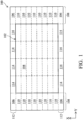
  • 1 ist eine Draufsicht einer integrierten Schaltung mit SRAM-Speichervorrichtungen (Static Random Access Memory), die gemäß verschiedenen Aspekten der vorliegenden Offenbarung in einigen Ausführungsformen aufgebaut ist.
  • 2 ist eine schematische Ansicht einer SRAM-Bitzelle in der integrierten Schaltung von 1 gemäß einigen Ausführungsformen.
  • 3 ist eine Draufsicht auf eine SRAM-Bitzelle in der integrierten Schaltung von 1 gemäß einigen Ausführungsformen.
  • 4A ist eine Schnittansicht der SRAM-Bitzelle aus 3 entlang der gestrichelten Linie AA' in einem Abschnitt gemäß einigen Ausführungsformen.
  • 4B ist eine perspektivische Ansicht der SRAM-Bitzelle von 4A gemäß einigen Ausführungsformen.
  • 5 ist eine Draufsicht einer SRAM-Bitzelle in der integrierten Schaltung von 1 gemäß einigen Ausführungsformen.
  • 6 ist eine Schnittdarstellung einer SRAM-Bitzelle in der integrierten Schaltung von 1 gemäß einigen Ausführungsformen.
  • 7 ist eine Draufsicht der SRAM-Bitzelle von 3 mit einer Interconnect-Struktur, die gemäß einigen Ausführungsformen aufgebaut ist.
  • 8A, 8B und 8C sind Schnittansichten der SRAM-Bitzelle von 7 entlang der gestrichelten Linien AA', BB' und CC' gemäß einigen Ausführungsformen.
  • 9A ist eine Draufsicht der integrierten Schaltungsstruktur mit zwei benachbarten SRAM-Bitzellen, die gemäß einigen Ausführungsformen aufgebaut ist.
  • 9B ist eine Schnittansicht der integrierten Schaltungsstruktur von 9A entlang der gestrichelten Linie AA', die gemäß einigen Ausführungsformen aufgebaut ist.
  • 9C und 9D sind grafische Ansichten zur Veranschaulichung der Eigenschaften der integrierten Schaltungsstruktur von 9A und 9B, die gemäß einigen Ausführungsformen aufgebaut ist.
  • 10A ist eine Schnittansicht der integrierten Schaltungsstruktur, die gemäß einigen Ausführungsformen aufgebaut ist.
  • 10B ist eine Schnittansicht der integrierten Schaltungsstruktur, die gemäß einigen Ausführungsformen aufgebaut ist.
  • 11A ist eine Draufsicht der integrierten Schaltungsstruktur mit zwei benachbarten SRAM-Bitzellen, die gemäß einigen Ausführungsformen aufgebaut ist.
  • 11B ist eine Schnittansicht der integrierten Schaltungsstruktur von 11A entlang der gestrichelten Linie AA', die gemäß einer Ausführungsform aufgebaut ist.
  • 12A ist eine Draufsicht der integrierten Schaltungsstruktur mit zwei benachbarten SRAM-Bitzellen, die gemäß einigen Ausführungsformen aufgebaut ist.
  • 12B ist eine Schnittansicht der integrierten Schaltungsstruktur von 12A entlang der gestrichelten Linie AA', die gemäß einer Ausführungsform aufgebaut ist.
  • 13A ist eine Draufsicht der integrierten Schaltungsstruktur mit zwei benachbarten SRAM-Bitzellen, die gemäß einigen Ausführungsformen aufgebaut ist.
  • 13B ist eine Schnittansicht der integrierten Schaltungsstruktur von 13A entlang der gestrichelten Linie AA', die gemäß einer Ausführungsform aufgebaut ist.
  • 14 ist ein Flussdiagramm eines Verfahrens zum Erzeugen eines asymmetrischen Layouts einer integrierten Schaltung mit mehreren SRAM-Zellen, die gemäß einigen Ausführungsformen aufgebaut ist.
Aspects of the present disclosure are best understood by reference to the following detailed description taken in conjunction with the accompanying drawings. It is to be understood that the various features are not drawn to scale in accordance with industry practice. In fact, the dimensions of the various features may be arbitrarily increased or reduced for the sake of clarity of discussion. The various drawings and the respective description are provided in a Power Point file. In particular,
  • 1 is a top view of an integrated circuit including static random access memory (SRAM) storage devices constructed in accordance with various aspects of the present disclosure in some embodiments.
  • 2 is a schematic view of an SRAM bit cell in the integrated circuit of 1 according to some embodiments.
  • 3 is a top view of an SRAM bit cell in the integrated circuit of 1 according to some embodiments.
  • 4A is a cross-sectional view of the SRAM bit cell from 3 along the dashed line AA' in a section according to some embodiments.
  • 4B is a perspective view of the SRAM bit cell of 4A according to some embodiments.
  • 5 is a top view of an SRAM bit cell in the integrated circuit of 1 according to some embodiments.
  • 6 is a cross-sectional view of an SRAM bit cell in the integrated circuit of 1 according to some embodiments.
  • 7 is a top view of the SRAM bit cell of 3 with an interconnect structure constructed according to some embodiments.
  • 8A , 8B and 8C are sectional views of the SRAM bit cell of 7 along dashed lines AA', BB', and CC' according to some embodiments.
  • 9A is a top view of the integrated circuit structure with two adjacent SRAM bit cells constructed in accordance with some embodiments.
  • 9B is a sectional view of the integrated circuit structure of 9A along dashed line AA', constructed according to some embodiments.
  • 9C and 9D are graphical views to illustrate the properties of the integrated circuit structure of 9A and 9B constructed according to some embodiments.
  • 10A is a cross-sectional view of the integrated circuit structure constructed in accordance with some embodiments.
  • 10B is a cross-sectional view of the integrated circuit structure constructed in accordance with some embodiments.
  • 11A is a top view of the integrated circuit structure with two adjacent SRAM bit cells constructed in accordance with some embodiments.
  • 11B is a sectional view of the integrated circuit structure of 11A along the dashed line AA', constructed according to one embodiment.
  • 12A is a top view of the integrated circuit structure with two adjacent SRAM bit cells constructed in accordance with some embodiments.
  • 12B is a sectional view of the integrated circuit structure of 12A along the dashed line AA', constructed according to one embodiment.
  • 13A is a top view of the integrated circuit structure with two adjacent SRAM bit cells constructed in accordance with some embodiments.
  • 13B is a sectional view of the integrated circuit structure of 13A along the dashed line AA', constructed according to one embodiment.
  • 14 is a flowchart of a method for creating an asymmetric layout of an integrated circuit having multiple SRAM cells constructed in accordance with some embodiments.

AUSFÜHRLICHE BESCHREIBUNGDETAILED DESCRIPTION

Die folgende Offenbarung bietet viele verschiedene Ausführungsformen und Beispiele für die Implementierung verschiedener Merkmale des bereitgestellten Gegenstands. Zur Vereinfachung der vorliegenden Offenbarung werden im Folgenden spezifische Beispiele für Komponenten und Anordnungen beschrieben. Dies sind natürlich nur Beispiele und sollen nicht einschränkend sein. Beispielsweise kann die Ausbildung eines ersten Merkmals über oder auf einem zweiten Merkmal in der folgenden Beschreibung Ausführungsformen umfassen, bei denen das erste und das zweite Merkmal in direktem Kontakt gebildet sind, und kann auch Ausführungsformen umfassen, bei denen zusätzliche Merkmale zwischen dem ersten und dem zweiten Merkmal gebildet sein können, so dass das erste und das zweite Merkmal gegebenenfalls nicht in direktem Kontakt stehen. Ferner können Bezugszeichen in den verschiedenen Beispielen der vorliegenden Offenbarung wiederholt werden. Diese Wiederholung dient der Einfachheit und Klarheit und schreibt nicht grundsätzlich eine Beziehung zwischen den verschiedenen diskutierten Ausführungsformen und/oder Konfigurationen vor.The following disclosure provides many different embodiments and examples of implementing various features of the provided subject matter. To simplify the present disclosure, specific examples of components and arrangements are described below. Of course, these are only examples and are not intended to be limiting. For example, the formation of a first feature over or on a second feature in the following description may include embodiments where the first and second features are formed in direct contact, and may also include embodiments where additional features may be formed between the first and second features such that the first and second features may not be in direct contact. Furthermore, reference numerals may be repeated throughout the various examples of the present disclosure. This repetition is for simplicity and clarity and does not necessarily dictate a relationship between the various embodiments and/or configurations discussed.

Ferner können hier zur Vereinfachung der Beschreibung räumlich relative Begriffe wie „unter“, „unten“, „abwärts“, „über“, „oben“, „aufwärts“ und dergleichen verwendet werden, um die Beziehung eines Elements oder Merkmals zu einem anderen Element oder Merkmal wie in den Zeichnungen dargestellt zu beschreiben. Die räumlich relativen Begriffe sollen neben der in den Zeichnungen dargestellten Ausrichtung auch andere Ausrichtungen der Vorrichtung während Benutzung oder Betrieb umfassen. Die Vorrichtung kann anders ausgerichtet sein (um 90 Grad gedreht oder in anderen Ausrichtungen) und die hier verwendeten räumlich relativen Bezeichnungen können ebenfalls entsprechend interpretiert werden. Wenn eine Zahl oder ein Zahlenbereich mit „etwa“, „näherungsweise“ oder dergleichen beschrieben wird, soll der Begriff Zahlen umfassen, die innerhalb von +/- 10 % der beschriebenen Zahl liegen, sofern nicht anders angegeben. Beispielsweise umfasst der Begriff „etwa 5 nm“ den Dimensionsbereich von 4,5 nm bis 5,5 nm.Furthermore, for ease of description, spatially relative terms such as "below," "below," "downward," "above," "above," "upward," and the like may be used herein to describe the relationship of one element or feature to another element or feature as illustrated in the drawings. The spatially relative terms are intended to encompass other orientations of the device during use or operation in addition to the orientation illustrated in the drawings. The device may be oriented differently (rotated 90 degrees or in other orientations) and the spatially relative terms used herein may also be interpreted accordingly. When a number or range of numbers is described with "about," "approximately," or the like, the term is intended to encompass numbers that are within +/- 10% of the number described, unless otherwise specified. For example, the term "about 5 nm" encompasses the dimensional range of 4.5 nm to 5.5 nm.

Die vorliegende Offenbarung stellt verschiedene Ausführungsformen einer SRAM-Vorrichtungsstruktur (Static Random Access Memory) und ein Verfahren zu deren Herstellung bereit. Insbesondere bietet die vorliegende Offenbarung verschiedene Ausführungsformen der SRAM-Vorrichtungsstruktur mit Stromversorgungsleitungen (wie höhere Stromversorgungsleitungen Vdd, niedrigere Stromversorgungsleitungen Vss), Bitleitungen und Wortleitungen, die auf Vorderseite und Rückseite des Substrats verteilt sind, so dass die Gesamtvorrichtungsleistung unter verschiedenen Kompromissparametern, wie Metallrouting-Widerstand und parasitäre Kapazität, verbessert wird.The present disclosure provides various embodiments of a static random access memory (SRAM) device structure and a method of manufacturing the same. In particular, the present disclosure provides various embodiments of the SRAM device structure with power supply lines (such as higher power supply lines Vdd, lower power supply lines Vss), bit lines, and word lines distributed on the front and back sides of the substrate such that the overall device performance is improved under various trade-off parameters such as metal routing resistance and parasitic capacitance.

1 ist eine Draufsicht einer integrierten Schaltungsstruktur (IC) 100, die gemäß verschiedenen Aspekten der vorliegenden Offenbarung in einer Ausführungsform aufgebaut ist. In einigen Ausführungsformen ist die integrierte Schaltungsstruktur 100 auf ebenen aktiven Bereichen gebildet und umfasst Feldeffekttransistoren (FETs). In einigen Ausführungsformen ist die integrierte Schaltung 100 auf aktiven Bereichen mit Finnen gebildet und umfasst FinFETs (Fin-Field-Effect-Transistoren). In einigen Ausführungsformen umfasst die integrierte Schaltungsstruktur 100 andere dreidimensionale aktive Bereiche wie beispielsweise mehrere vertikal auf dem Substrat gestapelte Kanäle. Der entsprechende FET umfasst einen Gatestapel um die mehreren vertikal gestapelten Kanäle herum, weshalb er auch als eine Gate-All-Around-FET-Struktur bezeichnet wird. Die integrierte Schaltungsstruktur 100 umfasst eine SRAM-Schaltung (Static Random Access-Memory) mit einem SRAM-Array 102 von mehreren SRAM-Bitzellen (oder SRAM-Zellen) 104, die in einem Array angeordnet sind, das sich über mehrere Spalten und mehrere Zeilen erstreckt. Die integrierte Schaltungsstruktur 100 kann ferner andere Vorrichtungs-/Schaltungsmodule (wie Logikvorrichtungen, Hochfrequenzvorrichtungen, Bildsensorvorrichtungen, DRAM-Vorrichtungen (Dynamic Random Access Memory) oder eine Kombination davon) aufweisen, die mit den SRAM-Vorrichtungen integriert sind. In den vorliegenden Ausführungsformen erstreckt sich jede Spalte der SRAM-Bitzellen 104 in dem Array entlang der X-Richtung und jede Zeile entlang der Y-Richtung. Beispielsweise kann jede Spalte N1 SRAM-Bitzellen enthalten, die in einer Zeile (einer Spalte) entlang der X-Richtung angeordnet sind, und jede Zeile kann N2 SRAM-Bitzellen enthalten, die in einer Zeile (einer Reihe) entlang der Y-Richtung angeordnet sind. Mit anderen Worten umfasst das SRAM-Array 102 SRAM-Bitzellen, die in N1 Zeilen und N2 Spalten angeordnet sind. In einigen Beispielen des SRAM-Arrays 102 umfasst jede Spalte 8, 16, 32, 64 oder 128 SRAM-Bitzellen und jede Zeile kann 4, 8, 16 oder 32 SRAM-Bitzellen umfassen. In dem in 1 dargestellten Beispiel umfasst das SRAM-Array 102 4 Spalten und 8 Zeilen. 1 is a top view of an integrated circuit (IC) structure 100 implemented in accordance with various aspects of the present disclosure in a Embodiment. In some embodiments, the integrated circuit structure 100 is formed on planar active regions and includes field effect transistors (FETs). In some embodiments, the integrated circuit 100 is formed on finned active regions and includes fin field effect transistors (FETs). In some embodiments, the integrated circuit structure 100 includes other three-dimensional active regions, such as multiple channels stacked vertically on the substrate. The corresponding FET includes a gate stack around the multiple vertically stacked channels, which is why it is also referred to as a gate-all-around FET structure. The integrated circuit structure 100 includes a static random access memory (SRAM) circuit having an SRAM array 102 of multiple SRAM bit cells (or SRAM cells) 104 arranged in an array spanning multiple columns and multiple rows. The integrated circuit structure 100 may further include other device/circuit modules (such as logic devices, radio frequency devices, image sensor devices, dynamic random access memory (DRAM) devices, or a combination thereof) integrated with the SRAM devices. In the present embodiments, each column of SRAM bit cells 104 in the array extends along the X direction and each row extends along the Y direction. For example, each column may include N1 SRAM bit cells arranged in a row (a column) along the X direction, and each row may include N2 SRAM bit cells arranged in a row (a row) along the Y direction. In other words, the SRAM array 102 includes SRAM bit cells arranged in N1 rows and N2 columns. In some examples of the SRAM array 102, each column includes 8, 16, 32, 64, or 128 SRAM bit cells and each row may include 4, 8, 16, or 32 SRAM bit cells. In the 1 In the example shown, the SRAM array 102 comprises 4 columns and 8 rows.

Die integrierte Schaltung 100 umfasst ferner Eck-Dummy-Zellen 106, die an vier Ecken des SRAM-Arrays 102 angeordnet sind, und Randbänder, wie Wortzeilen-Randbänder (WL-Randbänder) 108, die an Zeilenrändern des SRAM-Arrays 102 angeordnet sind, und Bitzeilen-Randbänder (BL-Randbänder) 112, die an Spaltenrändern des SRAM-Arrays 102 angeordnet sind. Jedes WL-Randband 108 umfasst mehrere WL-Randzellen 110, die in einer Linie entlang der X-Richtung angeordnet sind, und jedes BL-Randband 112 umfasst mehrere BL-Randzellen 114, die in einer Linie entlang der Y-Richtung angeordnet sind. Diese Randbänder (108 und 110) sind Schaltungsbereiche, die nicht als SRAM-Bitzellen dienen, sondern andere Funktionen erfüllen, wie später beschrieben.The integrated circuit 100 further includes corner dummy cells 106 arranged at four corners of the SRAM array 102 and edge bands such as word line (WL) edge bands 108 arranged at row edges of the SRAM array 102 and bit line (BL) edge bands 112 arranged at column edges of the SRAM array 102. Each WL edge band 108 includes a plurality of WL edge cells 110 arranged in a line along the X direction, and each BL edge band 112 includes a plurality of BL edge cells 114 arranged in a line along the Y direction. These edge bands (108 and 110) are circuit regions that do not serve as SRAM bit cells but perform other functions as described later.

Jede SRAM-Bitzelle 104 umfasst zwei Inverter, die kreuzgekoppelt sind, um ein Datenbit zu speichern, und umfasst ferner ein Pass-Gate, das elektrisch mit den beiden Invertern verbunden ist, um aus der SRAM-Bitzelle zu lesen und in sie zu schreiben. Die SRAM-Bitzelle 104 ist in 2 in einer schematischen Ansicht weiter dargestellt, die gemäß einigen Ausführungsformen aufgebaut ist. Die SRAM-Bitzelle 104 enthält eine erste Pull-Up-Vorrichtung (PU-1) und eine erste Pull-Down-Vorrichtung (PD-1), die mit einem ersten Inverter verbunden sind. Die SRAM-Bitzelle 104 enthält außerdem eine zweite Pull-Up-Vorrichtung (PU-1) und eine zweite Pull-Down-Vorrichtung (PD-1), die mit einem zweiten Inverter verbunden sind. Der erste und der zweite Inverter sind kreuzgekoppelt, um eine Datenspeichereinheit zu bilden. Die SRAM-Bitzelle 104 enthält außerdem ein Pass-Gate, das für das Lesen und Schreiben von Daten elektrisch mit den beiden Invertern verbunden ist. In der vorliegenden Ausführungsform umfasst die SRAM-Bitzelle 104 eine Dual-Port-SRAM-Vorrichtung mit zwei Pass-Gates (PG-1 und PG-2). Die SRAM-Bitzelle 104 enthält Feldeffekttransistoren (FETs), um Pass-Gate(s) und die Inverter zu bilden. In der vorliegenden Ausführungsform enthält jede der Pull-Up-Vorrichtungen (PU-1 und PU-2) einen nFET; jede der Pull-Down-Vorrichtungen (PD-1 und PD-2) enthält einen nFET; und jede der Pull-Up-Vorrichtungen (PU-1 und PU-2) enthält einen pFET. Die Pull-Down-Vorrichtungen, die Pull-Up-Vorrichtungen und die Pass-Gates können jeweils mehr als einen jeweiligen FET oder eine andere Anzahl von FETS enthalten, um die Leistung der SRAM-Bitzelle einzustellen, beispielsweise den Senkestrom, die Zugriffsgeschwindigkeit und/oder die Zuverlässigkeit der Vorrichtung. Beispielsweise ist die Anzahl der FETs in den Pull-Down-Vorrichtungen größer als die Anzahl der FETs in den Pass-Gate-Vorrichtungen. In einigen Ausführungsformen können diese zusätzlichen Pull-Down-Vorrichtungen in zusätzlichen aktiven Finnenbereichen gebildet sein. Alternativ wird die SRAM-Bitzelle 104 auf den mehreren vertikal gestapelten Kanälen gebildet, aber die Pull-Down-Vorrichtungen der SRAM-Bitzelle 104 werden auf den vertikal gestapelten Kanälen mit einer größeren Anzahl von Kanälen gebildet als die für Pass-Gate-Vorrichtungen oder Pull-Up-Vorrichtungen.Each SRAM bit cell 104 includes two inverters cross-coupled to store a bit of data and further includes a pass gate electrically connected to the two inverters for reading from and writing to the SRAM bit cell. The SRAM bit cell 104 is in 2 further illustrated in a schematic view constructed in accordance with some embodiments. The SRAM bit cell 104 includes a first pull-up device (PU-1) and a first pull-down device (PD-1) connected to a first inverter. The SRAM bit cell 104 also includes a second pull-up device (PU-1) and a second pull-down device (PD-1) connected to a second inverter. The first and second inverters are cross-coupled to form a data storage unit. The SRAM bit cell 104 also includes a pass gate electrically connected to the two inverters for reading and writing data. In the present embodiment, the SRAM bit cell 104 includes a dual-port SRAM device with two pass gates (PG-1 and PG-2). The SRAM bit cell 104 includes field effect transistors (FETs) to form the pass gate(s) and the inverters. In the present embodiment, each of the pull-up devices (PU-1 and PU-2) includes an nFET; each of the pull-down devices (PD-1 and PD-2) includes an nFET; and each of the pull-up devices (PU-1 and PU-2) includes a pFET. The pull-down devices, the pull-up devices, and the pass gates may each include more than one respective FET or a different number of FETs to adjust the performance of the SRAM bit cell, such as the sink current, the access speed, and/or the reliability of the device. For example, the number of FETs in the pull-down devices is greater than the number of FETs in the pass gate devices. In some embodiments, these additional pull-down devices may be formed in additional active fin regions. Alternatively, the SRAM bit cell 104 is formed on the multiple vertically stacked channels, but the pull-down devices of the SRAM bit cell 104 are formed on the vertically stacked channels with a larger number of channels than those for pass-gate devices or pull-up devices.

Insbesondere sind die Drains der ersten Pull-Up-Vorrichtung (PU-1) und der ersten Pull-Down-Vorrichtung (PD-1) elektrisch miteinander verbunden und definieren einen ersten Drain-Knoten (oder ersten Knoten) 202. Die Drains der zweiten Pull-Up-Vorrichtung (PU-2) und der zweiten Pull-Down-Vorrichtung (PD-2) sind elektrisch miteinander verbunden und definieren einen zweiten Drain-Knoten (oder zweiten Knoten) 204. Die Gates von PU-1 und PD-1 sind elektrisch miteinander verbunden und mit dem zweiten Knoten 204 gekoppelt. Die Gates von PU-2 und PD-2 sind elektrisch miteinander verbunden und mit dem ersten Knoten 202 gekoppelt. Die Sources von PU-1 und PU-2 sind elektrisch mit der Stromversorgungsleitung (Vdd-Leitung) verbunden. Die Sources von PD-1 und PD-2 sind elektrisch mit einer komplementären Stromversorgungsleitung (Vss-Leitung) verbunden.In particular, the drains of the first pull-up device (PU-1) and the first pull-down device (PD-1) are electrically connected to each other and define a first drain node (or first node) 202. The drains of the second pull-up device (PU-2) and the second pull-down device (PD-2) are electrically connected to each other and define a second drain node (or second node) 204. The gates of PU-1 and PD-1 are electrically connected to each other and coupled to the second node 204. The gates of PU-2 and PD-2 are electrically connected to each other and coupled to the first node 202. The sources of PU-1 and PU-2 are electrically connected to the power supply line (Vdd line). The sources of PD-1 and PD-2 are electrically connected to a complementary power supply line (Vss line).

Wie in 2 gezeigt, enthält die SRAM-Bitzelle 104 zwei Ports: einen ersten Port, der mit dem ersten Pass-Gate (PG-1) verbunden ist, und einen zweiten Port, der mit dem zweiten Pass-Gate (PG-2) verbunden ist. Die Pass-Gate-Vorrichtungen umfassen jeweils einen nFET. In einigen Ausführungsformen kann jedes Pass-Gate, wie oben erwähnt, mehr als einen FET enthalten. Der Drain von PG-1 ist elektrisch mit einer Bitleitung (BL) verbunden. Die Source von PG-1 ist elektrisch mit dem ersten Knoten 202 verbunden. Das Gate von PG-1 ist elektrisch mit einer Wortleitung (WL) verbunden. Der Drain von PG-2 ist elektrisch mit einer komplementären Bitleitung oder komplementären Bitleitung (BLB) verbunden. Die Source von PG-2 ist elektrisch mit dem zweiten Knoten 204 verbunden. Das Gate von PG-2 ist elektrisch mit einer komplementären Wortleitung oder komplementären Wortleitung (WLB) verbunden. Verschiedene nFETs und pFETs können durch jede geeignete Technologie gebildet werden, wie beispielsweise finnenartige FETs (FinFETs), die n-Typ FinFETs (nFinFETs) und p-Typ FinFETs (pFinFETs) umfassen. In einer Ausführungsform werden die verschiedenen nFinFETs und pFinFETs durch einen Prozess gebildet, der Ätzen eines Halbleiters zur Bildung von Gräben, teilweises Füllen (beispielsweise durch ein Verfahren umfassend Abscheiden, chemisch-mechanisches Polieren und Ätzen zur Aussparung) der Gräben zur Bildung von STI-Merkmalen (Shallow Trench Isolation) und von aktiven Finnenbereichen umfasst. In einer weiteren Ausführungsform wird eine Epitaxie-Halbleiterschicht selektiv auf dem aktiven Finnenbereich gebildet. In einer anderen Ausführungsform werden die verschiedenen FinFETs durch einen Prozess gebildet, der das Abscheiden einer Schicht dielektrischen Materials auf dem Halbleitersubstrat, das Ätzen der Schicht dielektrischen Materials zur Bildung von Öffnungen und selektives epitaktisches Aufwachsen eines Halbleitermaterials (wie Silizium) auf dem Halbleitersubstrat in den Öffnungen umfasst, um aktive Finnenbereiche und STI-Merkmale zu bilden. In einer anderen Ausführungsform können die verschiedenen FinFETs verspannte Merkmale aufweisen für eine verbesserte Mobilität und Vorrichtungsleistung. Beispielsweise können die pFinFETs epitaktisch gewachsenes Silizium-Germanium auf einem Siliziumsubstrat aufweisen. Die nFinFETs können epitaktisch gewachsenes Siliziumkarbid auf dem Siliziumsubstrat aufweisen. In einer anderen Ausführungsform werden die Gatestapel in verschiedenen FinFETs unter Verwendung der High-k/Metall-Gate-Technologie gebildet, bei der die Gatedielektrikumschicht ein high-k-dielektrisches Material enthält und die Gateelektrode Metall enthält.As in 2 As shown, the SRAM bit cell 104 includes two ports: a first port connected to the first pass gate (PG-1) and a second port connected to the second pass gate (PG-2). The pass gate devices each include an nFET. In some embodiments, each pass gate may include more than one FET, as mentioned above. The drain of PG-1 is electrically connected to a bit line (BL). The source of PG-1 is electrically connected to the first node 202. The gate of PG-1 is electrically connected to a word line (WL). The drain of PG-2 is electrically connected to a complementary bit line or complementary bit line (BLB). The source of PG-2 is electrically connected to the second node 204. The gate of PG-2 is electrically connected to a complementary word line or complementary word line (WLB). Various nFETs and pFETs may be formed by any suitable technology, such as fin-like FETs (FinFETs), which include n-type FinFETs (nFinFETs) and p-type FinFETs (pFinFETs). In one embodiment, the various nFinFETs and pFinFETs are formed by a process that includes etching a semiconductor to form trenches, partially filling (e.g., by a process including deposition, chemical mechanical polishing, and recess etching) the trenches to form shallow trench isolation (STI) features and fin active regions. In another embodiment, an epitaxial semiconductor layer is selectively formed on the fin active region. In another embodiment, the various FinFETs are formed by a process that includes depositing a layer of dielectric material on the semiconductor substrate, etching the layer of dielectric material to form openings, and selectively epitaxially growing a semiconductor material (such as silicon) on the semiconductor substrate in the openings to form fin active regions and STI features. In another embodiment, the various FinFETs may include strained features for improved mobility and device performance. For example, the pFinFETs may include epitaxially grown silicon germanium on a silicon substrate. The nFinFETs may include epitaxially grown silicon carbide on the silicon substrate. In another embodiment, the gate stacks in various FinFETs are formed using high-k/metal gate technology, where the gate dielectric layer includes a high-k dielectric material and the gate electrode includes metal.

3 ist eine Draufsicht eines Teils der integrierten Schaltung 100, insbesondere einer SRAM-Bitzelle 104, die gemäß einigen Ausführungsformen aufgebaut ist. Wie in 3 dargestellt, umfasst die integrierte Schaltung 100 eine n-dotierte Wanne (n-Wanne) 302, die in der Mitte der SRAM-Bitzelle 104 gebildet ist. Die n-Wanne 302 kann eine längliche Form aufweisen, die in der X-Richtung orientiert ist, und kann sich entlang der X-Richtung über mehrere SRAM-Bitzellen erstrecken. Die integrierte Schaltung 100 umfasst eine erste p-dotierte Wanne (p-Wanne) 304 und eine zweite p-Wanne 306, die an den Seiten der n-Wanne 302 gebildet sind und jeweils eine längliche, in X-Richtung orientierte Form aufweisen. Die p-Wannen 304 und 306 können sich auch entlang der X-Richtung über mehrere SRAM-Bitzellen erstrecken. Die integrierte Schaltung 100 umfasst verschiedene aktive Bereiche 308, die in den jeweiligen dotierten Wannen (wie 302, 304 und 306) angeordnet sind und auf denen verschiedene FETs gebildet sind. Diese aktiven Bereiche 308 sind von Isolationsmerkmalen wie beispielsweise STI-Merkmalen, umgeben und durch diese definiert. In einigen Ausführungsformen sind die aktiven Bereiche 308 finnenartige aktive Bereiche, die sich über die Isolationsmerkmale (wie STI-Merkmale) erstrecken. In einigen Ausführungsformen weisen die finnenartigen aktiven Bereiche 308 längliche Formen auf, die in X-Richtung ausgerichtet sind und sich über mehrere SRAM-Bitzellen erstrecken können. Die Gates 310 der FETs sind auf den aktiven Bereichen 308 gebildet und entlang der Y-Richtung ausgerichtet. Insbesondere erstrecken sich einige aktive Bereiche 308 von der n-Wanne 302 zu der benachbarten p-Wanne (beispielsweise 304 oder 306), so dass jeweilige FETs (beispielsweise PU-1 und PD-1 oder PU-2 und PD-2) ein gemeinsames Gate teilen. In der vorliegenden Ausführungsform ist das Gate 310 sowohl über der n-Wanne 302 als auch über der p-Wanne 304 mit einem pFET für die erste Pull-Up-Vorrichtung (PU-1) in der n-Wanne 302 verbunden und mit einem nFET für die erste Pull-Down-Vorrichtung (PD-1) in der p-Wanne 304 verbunden; das Gate 310 sowohl über der n-Wanne 302 als auch über der p-Wanne 306 ist mit einem pFET für die zweite Pull-Up-Vorrichtung (PU-2) in der n-Wanne 302 verbunden und mit einem nFET für die zweite Pull-Down-Vorrichtung (PD-2) in der p-Wanne 306 verbunden; der pFET für das erste Pass-Gate (PG-1) ist in der p-Wanne 304 gebildet; und der pFET für das zweite Pass-Gate (PG-2) ist in der p-Wanne 306 gebildet. 3 is a top view of a portion of the integrated circuit 100, particularly an SRAM bit cell 104, constructed in accordance with some embodiments. As shown in 3 As shown, the integrated circuit 100 includes an n-doped well (n-well) 302 formed in the center of the SRAM bit cell 104. The n-well 302 may have an elongated shape oriented in the X direction and may extend along the X direction across multiple SRAM bit cells. The integrated circuit 100 includes a first p-doped well (p-well) 304 and a second p-well 306 formed on the sides of the n-well 302, each having an elongated shape oriented in the X direction. The p-wells 304 and 306 may also extend along the X direction across multiple SRAM bit cells. The integrated circuit 100 includes various active regions 308 disposed in the respective doped wells (such as 302, 304, and 306) and on which various FETs are formed. These active regions 308 are surrounded by and defined by isolation features, such as STI features. In some embodiments, the active regions 308 are fin-like active regions that extend across the isolation features (such as STI features). In some embodiments, the fin-like active regions 308 have elongated shapes that are aligned in the X-direction and may extend across multiple SRAM bit cells. The gates 310 of the FETs are formed on the active regions 308 and aligned along the Y-direction. In particular, some active regions 308 extend from the n-well 302 to the adjacent p-well (e.g., 304 or 306) such that respective FETs (e.g., PU-1 and PD-1 or PU-2 and PD-2) share a common gate. In the present embodiment, the gate 310 above both the n-well 302 and the p-well 304 is connected to a pFET for the first pull-up device (PU-1) in the n-well 302 and connected to an nFET for the first pull-down device (PD-1) in the p-well 304; the gate 310 over both the n-well 302 and the p-well 306 is connected to a pFET for the second pull-up device (PU-2) in the n-well 302 and to an nFET for the second pull-down device (PD-2) in the p-well 306; the pFET for the first pass gate (PG-1) is formed in the p-well 304; and the pFET for the second pass gate (PG-2) is formed in the p-well 306.

4A ist eine Schnittansicht eines Teils der integrierten Schaltung 100, beispielsweise entlang der gestrichelten Linie AA' in 3, die gemäß einigen Ausführungsformen aufgebaut ist. 4B ist eine perspektivische Ansicht der integrierten Schaltung 100 von 4A, die gemäß einigen Ausführungsformen aufgebaut ist. In 4A und 4B umfasst die integrierte Schaltung 100 ein Halbleitersubstrat 402. Das Halbleitersubstrat 402 enthält Silizium. Alternativ enthält das Halbleitersubstrat 402 Germanium, Silizium-Germanium oder andere geeignete Halbleitermaterialien. Die integrierte Schaltung 100 umfasst verschiedene Isolationsmerkmale 404 wie beispielsweise STI-Merkmale (Shallow Trench Isolation). Die integrierte Schaltung 100 umfasst ferner verschiedene aktive Bereiche 308 wie beispielsweise aktive Finnenbereiche, die auf dem Halbleitersubstrat 402 gebildet sind. In der dargestellten Ausführungsform, bei der die aktiven Bereiche 308 finnenförmig sind, werden die aktiven Bereiche 308 oberhalb der Isolationsmerkmale 404 extrudiert und sind von den Isolationsmerkmalen 404 umgeben und durch diese voneinander isoliert. Die integrierte Schaltung 100 umfasst ferner eine p-Wanne 304 und eine n-Wanne 302, die auf dem Halbleitersubstrat 402 gebildet sind. Verschiedene FETs sind auf den aktiven Bereichen 308 gebildet. Ein nFET ist auf den aktiven Bereichen 308 in der p-Wanne 304 angeordnet und ein pFET ist auf den aktiven Bereichen 308 in der n-Wanne 302 angeordnet. 4A is a sectional view of a portion of the integrated circuit 100, for example along the dashed line AA' in 3 constructed according to some embodiments. 4B is a perspective view of the integrated circuit 100 of 4A , which is constructed according to some embodiments. In 4A and 4B the integrated circuit 100 includes a semiconductor substrate 402. The semiconductor substrate 402 includes silicon. Alternatively, the semiconductor substrate 402 includes germanium, silicon germanium, or other suitable semiconductor materials. The integrated circuit 100 includes various isolation features 404, such as shallow trench isolation (STI) features. The integrated circuit 100 further includes various active regions 308, such as fin active regions, formed on the semiconductor substrate 402. In the illustrated embodiment where the active regions 308 are fin-shaped, the active regions 308 are extruded above the isolation features 404 and are surrounded by and isolated from each other by the isolation features 404. The integrated circuit 100 further includes a p-well 304 and an n-well 302 formed on the semiconductor substrate 402. Various FETs are formed on the active regions 308. An nFET is disposed on the active regions 308 in the p-well 304 and a pFET is disposed on the active regions 308 in the n-well 302.

Source/Drains (S/D) 406 sind auf den aktiven Bereichen 308 gebildet und ein Gate 310 ist auf dem aktiven Bereich 308 gebildet und zwischen dem jeweiligen Source und Drain 406 angeordnet. In dem vorliegenden Beispiel erstreckt sich das Gate 310 von dem ersten aktiven Bereich in der p-Wanne 304 zu dem zweiten aktiven Bereich in der n-Wanne 302, also als ein gemeinsames Gate, das von einem jeweiligen nFET und pFET gemeinsam genutzt wird. Das Gate 310 umfasst eine Gatedielektrikumschicht und eine Gateelektrode, die auf der dielektrischen Gate-Schicht angeordnet ist. Ferner können dielektrische Abstandhalter 408 an den Seitenwänden des Gates 310 und auch an den Seitenwänden der aktiven Bereiche 308 gebildet sein. Ein Kanal ist ein Abschnitt des aktiven Bereichs 308, der unter dem jeweiligen Gate 310 liegt. Die jeweiligen Source/Drain 406, das Gate 310 und der Kanal sind zu einem Feldeffekttransistor wie beispielsweise einem nFET oder einem pFET, gekoppelt.Source/Drains (S/D) 406 are formed on the active regions 308 and a gate 310 is formed on the active region 308 and disposed between the respective source and drain 406. In the present example, the gate 310 extends from the first active region in the p-well 304 to the second active region in the n-well 302, thus as a common gate shared by a respective nFET and pFET. The gate 310 includes a gate dielectric layer and a gate electrode disposed on the gate dielectric layer. Furthermore, dielectric spacers 408 may be formed on the sidewalls of the gate 310 and also on the sidewalls of the active regions 308. A channel is a portion of the active region 308 that underlies the respective gate 310. The respective source/drain 406, the gate 310 and the channel are coupled to a field effect transistor such as an nFET or a pFET.

In verschiedenen Ausführungsformen verwenden die Isolationsmerkmale 404 eine geeignete Isolationstechnologie wie beispielsweise LOCOS (Local Oxidation of Silicon) und/oder STI, um die verschiedenen Bereiche zu definieren und elektrisch zu isolieren. Das Isolationsmerkmal 404 enthält Siliziumoxid, Siliziumnitrid, Siliziumoxynitrid, andere geeignete dielektrische Materialien oder Kombinationen davon. Das Isolationsmerkmal 404 wird durch jedes geeignete Verfahren gebildet. Ein Beispiel für die Herstellung von STI-Merkmalen ist die Verwendung eines Lithografieprozesses, um einen Teil des Substrats freizulegen, das Ätzen eines Grabens in den freigelegten Teil des Substrats (beispielsweise durch Trockenätzen und/oder Nassätzen), das Füllen des Grabens (beispielsweise durch einen chemischen Gasphasenabscheidungsprozess) mit einem oder mehreren dielektrischen Materialien und das Planarisieren des Substrats und das Entfernen überschüssiger Teile des dielektrischen Materials/der dielektrischen Materialien durch einen Polierprozess wie beispielsweise CMP. In einigen Beispielen kann der gefüllte Graben eine mehrschichtige Struktur aufweisen, beispielsweise eine mit Siliziumnitrid oder Siliziumoxid gefüllte thermische Oxid-Auskleidungsschicht.In various embodiments, the isolation features 404 use a suitable isolation technology, such as LOCOS (Local Oxidation of Silicon) and/or STI, to define and electrically isolate the various regions. The isolation feature 404 includes silicon oxide, silicon nitride, silicon oxynitride, other suitable dielectric materials, or combinations thereof. The isolation feature 404 is formed by any suitable method. An example of fabricating STI features is using a lithography process to expose a portion of the substrate, etching a trench into the exposed portion of the substrate (e.g., by dry etching and/or wet etching), filling the trench (e.g., by a chemical vapor deposition process) with one or more dielectric materials, and planarizing the substrate and removing excess portions of the dielectric material(s) by a polishing process such as CMP. In some examples, the filled trench may have a multi-layer structure, such as a thermal oxide liner layer filled with silicon nitride or silicon oxide.

In einer anderen Ausführungsform enthalten die Gates 310 alternativ oder zusätzlich andere geeignete Materialien für die Schaltungsleistung und Fertigungsintegration. Beispielsweise umfasst die Gatedielektrikumschicht eine Schicht high-k-dielektrischen Materials, wie Metalloxid, Metallnitrid oder Metalloxynitrid. In verschiedenen Beispielen umfasst die Schicht high-k-dielektrischen Materials Metalloxid: ZrO2, Al2O3 und HfO2, gebildet durch ein geeignetes Abscheideverfahren. Die Gatedielektrikumschicht kann ferner eine Grenzflächenschicht aufweisen, die zwischen dem Halbleitersubstrat 402 und dem High-k-Dielektrikum angeordnet ist.In another embodiment, the gates 310 alternatively or additionally include other suitable materials for circuit performance and manufacturing integration. For example, the gate dielectric layer comprises a layer of high-k dielectric material, such as metal oxide, metal nitride, or metal oxynitride. In various examples, the layer of high-k dielectric material comprises metal oxide: ZrO2, Al2O3, and HfO2, formed by a suitable deposition process. The gate dielectric layer may further include an interface layer disposed between the semiconductor substrate 402 and the high-k dielectric.

Die Gateelektrode enthält Metall, wie beispielsweise Aluminium, Kupfer, Wolfram, Metallsilizid, dotiertes Polysilizium, anderes geeignetes leitfähiges Material oder eine Kombination davon. Die Gateelektrode kann mehrere leitfähige Schichten umfassen, die wie eine Deckschicht, eine Austrittsarbeitsmetallschicht, eine Sperrschicht und eine Füllmetallschicht (beispielsweise Aluminium oder Wolfram) gestaltet sind. Mehrere leitfähige Schichten, die für die Austrittsarbeit passend zu einem nFET und einem pFET gestaltet sind. In einigen Ausführungsformen enthält die Gateelektrode für den nFET ein Austrittsarbeitsmetall mit einer Zusammensetzung, die mit einer Austrittsarbeit von 4,2 eV oder weniger ausgestaltet ist, und die Gateelektrode für den pFET enthält ein Austrittsarbeitsmetall mit einer Zusammensetzung, die mit einer Austrittsarbeit von 5,2 eV oder größer ausgestaltet ist. Beispielsweise enthält die Austrittsarbeitsmetallschicht für nFET Tantal, Titanaluminium, Titanaluminiumnitrid oder eine Kombination davon. In einem anderen Beispiel enthält die Austrittsarbeitsmetallschicht für pFET Titannitrid, Tantalnitrid oder eine Kombination davon.The gate electrode includes metal, such as aluminum, copper, tungsten, metal silicide, doped polysilicon, other suitable conductive material, or a combination thereof. The gate electrode may include a plurality of conductive layers configured such as a cap layer, a work function metal layer, a barrier layer, and a fill metal layer (e.g., aluminum or tungsten). A plurality of conductive layers configured for work function matching an nFET and a pFET. In some embodiments, the gate electrode for the nFET includes a work function metal having a composition configured with a work function of 4.2 eV or less, and the gate electrode for the pFET includes a work function metal having a composition configured with a work function of 5.2 eV or greater. For example, the work function metal layer for nFET includes tantalum, titanium aluminum, titanium aluminum nitride, or a combination thereof. In another example, the work function metal layer for pFET includes titanium nitride, tantalum nitride, or a combination thereof.

5 ist eine Draufsicht eines Teils der integrierten Schaltung 100, insbesondere einer SRAM-Bitzelle 104, die gemäß einigen Ausführungsformen aufgebaut ist. Wie in 5 dargestellt, umfasst die integrierte Schaltung 100 zwei oder mehr erste Pull-Down-Vorrichtungen (PD-1), die auf einer Anzahl (N) von aktiven Finnenbereichen 308 in der p-Wanne 304 gebildet sind, und zwei oder mehr zweite Pull-Down-Vorrichtungen (PD-2), die auf der Anzahl (N) von aktiven Finnenbereichen 308 in der p-Wanne 306 gebildet sind. In dem dargestellten Beispiel beträgt die Anzahl N 2. In anderen Beispielen kann die Anzahl N 3, 4 oder so weiter betragen. 5 is a top view of a portion of the integrated circuit 100, particularly an SRAM bit cell 104, constructed in accordance with some embodiments. As shown in 5 shown, includes the integrated circuit 100 includes two or more first pull-down devices (PD-1) formed on a number (N) of fin active regions 308 in p-well 304 and two or more second pull-down devices (PD-2) formed on the number (N) of fin active regions 308 in p-well 306. In the illustrated example, the number N is 2. In other examples, the number N may be 3, 4, or so on.

6 ist eine Schnittansicht eines Teils der integrierten Schaltung 100, die gemäß einigen Ausführungsformen aufgebaut ist. In 6 weist die integrierte Schaltung 100 eine vertikal gestapelte Kanalstruktur auf, in der mehrere Kanäle vertikal gestapelt sind. Insbesondere umfasst die integrierte Schaltung 100 ein Substrat 602 und mehrere Kanäle 604, die über dem Substrat 602 gebildet sind. Die integrierte Schaltung 100 umfasst ferner ein Gate 606, das um die Kanäle 604 herum gebildet ist, und Source/Drain-Merkmale (S/D-Merkmale) 608, die auf beiden Seiten des Gates 606 angeordnet sind. Insbesondere umwickelt das Gate 606 jeden der mehreren vertikal gestapelten Kanäle 604, die sich zwischen den S/D-Merkmalen 608 erstrecken, welche auf beiden Seiten des Gates 606 angeordnet sind. Die integrierte Schaltung 100 umfasst ferner weitere Merkmale, wie beispielsweise innere Abstandhalter 610 (aus einem oder mehreren dielektrischen Materialien), die zwischen dem Gate 606 und den S/D-Merkmalen 608 angeordnet sind; Gate-Abstandhalter 612, die an den Seitenwänden des Gate 606 angeordnet sind; eine dotierte Wand 614 (beispielsweise eine N-Wanne oder eine P-Wanne); und eine ILD-Schicht (Interlevel Dielectric) 616. Das Gate 606 umfasst eine Gatedielektrikumschicht und eine Gateelektrode. Die Gatedielektrikumschicht enthält ein oder mehrere dielektrische Materialien wie beispielsweise ein High-k-Dielektrikum. Die Gatedielektrikumschicht kann ferner eine Grenzflächenschicht (beispielsweise Siliziumoxid) aufweisen, die unter dem high-k-dielektrischen Material liegt. Die Gateelektrode enthält ein oder mehrere leitfähige Materialien wie beispielsweise eine Abdeckschicht, ein Austrittsarbeitsmetall und ein Füllmetall. Somit sind die verschiedenen nFETs und pFETs der SRAM-Bit-Zelle 104 diesen vertikal gestapelten Kanälen gebildet. Ferner kann die erste Anzahl N1 der Kanäle für eine Pull-Down-Vorrichtung und die zweite Anzahl N2 der Kanäle für eine Pull-Up-Vorrichtung unterschiedlich ausgelegt sein, um die Leistung einer SRAM-Zelle einzustellen. Beispielsweise ist das Verhältnis N1/N2 so ausgelegt, dass es größer als 1 ist, wie beispielsweise N1/N2 = 2/1; 3/2; 5/3; und so weiter. 6 is a cross-sectional view of a portion of the integrated circuit 100 constructed in accordance with some embodiments. In 6 the integrated circuit 100 has a vertically stacked channel structure in which a plurality of channels are vertically stacked. In particular, the integrated circuit 100 includes a substrate 602 and a plurality of channels 604 formed above the substrate 602. The integrated circuit 100 further includes a gate 606 formed around the channels 604 and source/drain (S/D) features 608 disposed on either side of the gate 606. In particular, the gate 606 wraps around each of the plurality of vertically stacked channels 604 extending between the S/D features 608 disposed on either side of the gate 606. The integrated circuit 100 further includes other features, such as internal spacers 610 (made of one or more dielectric materials) disposed between the gate 606 and the S/D features 608; Gate spacers 612 disposed on the sidewalls of the gate 606; a doped wall 614 (e.g., an N-well or a P-well); and an interlevel dielectric (ILD) layer 616. The gate 606 includes a gate dielectric layer and a gate electrode. The gate dielectric layer includes one or more dielectric materials, such as a high-k dielectric. The gate dielectric layer may further include an interface layer (e.g., silicon oxide) underlying the high-k dielectric material. The gate electrode includes one or more conductive materials, such as a cap layer, a work function metal, and a fill metal. Thus, the various nFETs and pFETs of the SRAM bit cell 104 are formed from these vertically stacked channels. Furthermore, the first number N1 of channels for a pull-down device and the second number N2 of channels for a pull-up device may be designed differently to adjust the performance of an SRAM cell. For example, the ratio N1/N2 is designed to be greater than 1, such as N1/N2 = 2/1; 3/2; 5/3; and so on.

Diese FETs der SRAM-Bitzelle 104 sind ferner so verbunden, dass sie eine funktionale SRAM-Schaltung bilden. 7 ist eine fragmentarische Draufsicht der integrierten Schaltung 100, die gemäß einigen Ausführungsformen aufgebaut ist. 7 ist ähnlich wie 3, enthält jedoch eine Interconnect-Struktur, die die FETs gemäß 2 verbindet. Eine Interconnect-Struktur umfasst verschiedene leitfähige Merkmale wie beispielsweise Kontakte (Kontaktmerkmale); Durchkontaktierungen (Durchkontaktierungsmerkmale) und Metallleitungen, die in mehreren Metallschichten verteilt sind und eingerichtet sind, die beabsichtigten Verbindungen zu schaffen.These FETs of the SRAM bit cell 104 are further connected to form a functional SRAM circuit. 7 is a fragmentary plan view of integrated circuit 100 constructed in accordance with some embodiments. 7 is similar to 3 , but contains an interconnect structure that connects the FETs according to 2 An interconnect structure comprises various conductive features such as contacts (contact features); vias (via features) and metal lines distributed in multiple metal layers and configured to create the intended connections.

In 7 sind die Sources von PU-1 und PU-2 mit einer ersten Stromversorgungsleitung Vdd mit einer höheren Spannung verbunden; die Sources von PD-1 und PD-2 sind mit einer zweiten Stromversorgungsleitung Vss mit einer niedrigeren Spannung (beispielsweise einer Masseleitung) verbunden; die Drains von PG-1 und PG-2 sind mit einer Bitleitung (BL) und einer komplementären Bitleitung (BLB) verbunden; und die Gates von PG-1 und PG-2 sind mit einer Wortleitung (WL) und einer komplementären Wortleitung (WLB) verbunden. In einigen Ausführungsformen werden nur WL oder WLB von benachbarten SRAM-Zellen gemeinsam genutzt. In der vorliegenden Ausführungsform der integrierten Schaltung 100 umfasst jede SRAM-Zelle eine erste Vss und eine zweite Vss, wie in 7 dargestellt.In 7 the sources of PU-1 and PU-2 are connected to a first power supply line Vdd having a higher voltage; the sources of PD-1 and PD-2 are connected to a second power supply line Vss having a lower voltage (e.g., a ground line); the drains of PG-1 and PG-2 are connected to a bit line (BL) and a complementary bit line (BLB); and the gates of PG-1 and PG-2 are connected to a word line (WL) and a complementary word line (WLB). In some embodiments, only WL or WLB is shared by neighboring SRAM cells. In the present embodiment of the integrated circuit 100, each SRAM cell includes a first Vss and a second Vss, as shown in 7 shown.

Diese Stromversorgungsleitungen (Vdd und Vss) und Signalleitungen (BL, BLB, WL und WLB) sind nicht alle auf der Vorderseite der integrierten Schaltungsstruktur 100 gebildet, sondern sind auf der Vorderseite und der Rückseite der integrierten Schaltungsstruktur 100 verteilt. Insbesondere umfasst die integrierte Schaltungsstruktur 100 eine vorderseitige Interconnect-Struktur und eine rückseitige Interconnect-Struktur, die auf der Vorderseite und der Rückseite der integrierten Schaltungsstruktur 100 angeordnet sind und eingerichtet sind, verschiedene Komponenten der Pull-Up-Vorrichtungen, Pull-Down-Vorrichtungen und Pass-Gate-Vorrichtungen zu verbinden, um SRAM-Bitzellen 104 zu bilden. Die Konfiguration wird unter Berücksichtigung verschiedener Faktoren und Parameter einschließlich der Größen der verschiedenen leitfähigen Merkmale, der Packungsdichte, des Widerstands der leitfähigen Merkmale, der parasitären Kapazitäten zwischen benachbarten leitfähigen Merkmalen, der Overlay-Verschiebung und der Verarbeitungsspielräume ausgestaltet. Wenn beispielsweise die leitfähigen Merkmale zu nahe beieinander liegen, kann die Overlay-Verschiebung zu Problemen bezüglich Kurzschluss und Leckströme führen; die Größen der leitfähigen Merkmale werden reduziert, was zu erhöhten Widerständen führt; die parasitären Kapazitäten werden ebenfalls erhöht; die Verarbeitungsspannen werden reduziert und so weiter. Wenn die Größe der leitfähigen Merkmale vergrößert wird, wird zwar die Widerstände der leitfähigen Merkmale reduziert, aber die Abstände zwischen den benachbarten leitfähigen Merkmalen verringern sich, was zu erhöhten parasitären Kapazitäten und geringeren Verarbeitungsspielräumen führt. Wenn abschirmende leitfähige Merkmale zwischen benachbarten leitfähigen Merkmalen angeordnet sind, werden die parasitären Kapazitäten reduziert. Allerdings wird die Packungsdichte verringert und/oder die Widerstände der leitfähigen Merkmale werden erhöht.These power supply lines (Vdd and Vss) and signal lines (BL, BLB, WL, and WLB) are not all formed on the front side of the integrated circuit structure 100, but are distributed on the front side and the back side of the integrated circuit structure 100. In particular, the integrated circuit structure 100 includes a front-side interconnect structure and a back-side interconnect structure arranged on the front side and the back side of the integrated circuit structure 100 and configured to connect various components of the pull-up devices, pull-down devices, and pass-gate devices to form SRAM bit cells 104. The configuration is designed taking into account various factors and parameters including the sizes of the various conductive features, packing density, resistance of the conductive features, parasitic capacitances between adjacent conductive features, overlay displacement, and processing margins. For example, if the conductive features are too close to each other, overlay shifting can cause short circuit and leakage problems; the sizes of the conductive features are reduced, resulting in increased resistances; the parasitic capacitances are also increased; the processing margins are reduced, and so on. If the size of the conductive features is increased, the resistances of the conductive features are reduced, but the distances between the adjacent conductive features are increased. Features are reduced, resulting in increased parasitic capacitances and reduced processing margins. When shielding conductive features are placed between adjacent conductive features, the parasitic capacitances are reduced. However, the packing density is reduced and/or the resistances of the conductive features are increased.

In der dargestellten Ausführungsform sind eine der Bitleitungen (BL und BLB) und eine der Stromversorgungsleitungen (Vdd und Vss) auf der Vorderseite und die jeweils andere der Bitleitungen (BL und BLB) und jeweils andere der Stromversorgungsleitungen (Vdd und Vss) auf der Rückseite der integrierten Schaltungsstruktur 100 gebildet. Gemäß einer weiteren Ausführungsform sind die BL und die zweite Stromversorgungsleitung (Vss), die mit der PD-2-Vorrichtung verbunden ist, auf der Rückseite gebildet; und die BLB und die zweite Stromversorgungsleitung (Vss), die mit der PD-1-Vorrichtung verbunden ist, und die erste Stromversorgungsleitung (Vdd), die sowohl mit der PU-1- als auch der PU-2-Vorrichtung verbunden ist, sind auf der Rückseite gebildet. Die integrierte Schaltungsstruktur 100 umfasst ferner einen stumpfgestoßenen Kontakt 620, der auf einer aktiven Region und einem Gate landet. Beispielsweise ist ein stumpfgestoßener Kontakt 620 (links in 7) mit dem gemeinsamen Gate von PU-2 und PD-2 und den Drain-Merkmalen von PU-1 und PD-1 verbunden. Ein weiterer stumpfgestoßener Kontakt 620 (rechts in 7) ist mit dem gemeinsamen Gate von PU-1 und PD-1 und den Drain-Merkmalen von PU-2 und PD-2 verbunden. Ferner können die Wortleitungen (WL und WLB) auf der Vorderseite, auf der Rückseite oder auf beiden Seiten gebildet sein. Beispielsweise wird eine der Wortleitungen (WL und WLB) auf der Vorderseite und die andere auf der Rückseite gebildet. Insbesondere können benachbarte Zellen unterschiedlich konfiguriert sein, um die Routingstrukturdichte auf der Vorderseite wie auf der Rückseite geeignet einzustellen. In dem dargestellten Beispiel wird die WL auf der Rückseite gebildet und die WLB wird auf der Vorderseite gebildet. Im weiteren Verlauf des Beispiels werden die WL und WLB in einer SRAM-Zelle von benachbarten Zellen gemeinsam genutzt.In the illustrated embodiment, one of the bit lines (BL and BLB) and one of the power supply lines (Vdd and Vss) are formed on the front side and the other of the bit lines (BL and BLB) and the other of the power supply lines (Vdd and Vss) are formed on the back side of the integrated circuit structure 100. According to another embodiment, the BL and the second power supply line (Vss) connected to the PD-2 device are formed on the back side; and the BLB and the second power supply line (Vss) connected to the PD-1 device and the first power supply line (Vdd) connected to both the PU-1 and PU-2 devices are formed on the back side. The integrated circuit structure 100 further includes a butt-butted contact 620 that lands on an active region and a gate. For example, a butt-butted contact 620 (left in 7 ) is connected to the common gate of PU-2 and PD-2 and the drain features of PU-1 and PD-1. Another butt-jointed contact 620 (right in 7 ) is connected to the common gate of PU-1 and PD-1 and the drain features of PU-2 and PD-2. Furthermore, the word lines (WL and WLB) may be formed on the front side, on the back side, or on both sides. For example, one of the word lines (WL and WLB) is formed on the front side and the other on the back side. In particular, adjacent cells may be configured differently to appropriately adjust the routing structure density on the front side as well as on the back side. In the illustrated example, the WL is formed on the back side and the WLB is formed on the front side. In the remainder of the example, the WL and WLB in an SRAM cell are shared by adjacent cells.

Dies ist ferner in 8A, 8B und 8C als fragmentarische Schnittansichten von 7 entlang der gestrichelten Linien AA', BB' und CC' dargestellt. Die integrierte Schaltungsstruktur 100 umfasst ein Substrat 702 mit verschiedenen darauf gebildeten Vorrichtungen (Pull-Up-Vorrichtungen, Pull-Down-Vorrichtungen und Pass-Gate-Vorrichtungen) der SRAM-Bitzellen 104. Die integrierte Schaltungsstruktur 100 umfasst ferner eine vorderseitige Interconnect-Struktur 704, die auf der Vorderseite des Substrats 702 gebildet ist, und eine rückseitige Interconnect-Struktur 706, die auf der Rückseite des Substrats 702 gebildet ist. Die vorderseitige Interconnect-Struktur 704 kann Kontaktmerkmale 710, Durchkontaktierungsmerkmale 712 und Metallleitungen 714 umfassen, die in mehreren Metallschichten verteilt sind, wie beispielsweise der ersten Metallschicht nahe an dem Substrat, der zweiten Metallschicht über der ersten Metallschicht, der dritten Metallschicht über der zweiten Metallschicht und so weiter. Insbesondere umfasst die vorderseitige Interconnect-Struktur 704 Kontaktmerkmale 710, die auf Vorrichtungsmerkmalen wie Source/Drain-Merkmalen landen; Durchkontaktierungsmerkmale 712, die auf den Kontaktmerkmalen 710 landen; und Metallleitungen 714 (wie Metallleitungen in der ersten Metallschicht), die auf den Durchkontaktierungsmerkmalen 710 landen. Insbesondere ist die Metallleitung 714A durch das Durchkontaktierungsmerkmal 712A und das Kontaktmerkmal 710A nach unten mit der Source der Pull-Up-Vorrichtungen (PU-1 und PU-2) verbunden und nach oben mit der ersten Stromversorgungsleitung (Vdd) verbunden, weshalb diese auch als Vdd bezeichnet wird. Die Metallleitung 714B ist über das Durchkontaktierungsmerkmal 712B und das Kontaktmerkmal 710B mit der Source der Pull-Down-Vorrichtung (PD-1) nach unten und mit der zweiten Stromversorgungsleitung (Vss) nach oben verbunden und wird daher auch als Vss bezeichnet. Die Metallleitung 714C ist über das Durchkontaktierungsmerkmal 712C und das Kontaktmerkmal 710C mit dem Drain der Pass-Gate-Vorrichtung (PG-2) nach unten und mit der komplementären Bitleitung (BLB) nach oben verbunden, weshalb sie auch als BLB bezeichnet wird. Die Metallleitung 714D ist über das Merkmal 712D und das Kontaktmerkmal 710D mit der Gateelektrode der Pass-Gate-Vorrichtung (PG-1) nach unten und mit der Wortleitung (WL) nach oben verbunden, weshalb sie auch als WL bezeichnet wird.This is also in 8A , 8B and 8C as fragmentary sectional views of 7 along dashed lines AA', BB', and CC'. The integrated circuit structure 100 includes a substrate 702 with various devices (pull-up devices, pull-down devices, and pass-gate devices) of the SRAM bit cells 104 formed thereon. The integrated circuit structure 100 further includes a front-side interconnect structure 704 formed on the front side of the substrate 702 and a back-side interconnect structure 706 formed on the back side of the substrate 702. The front-side interconnect structure 704 may include contact features 710, via features 712, and metal lines 714 distributed in multiple metal layers, such as the first metal layer proximate to the substrate, the second metal layer above the first metal layer, the third metal layer above the second metal layer, and so on. In particular, the front-side interconnect structure 704 includes contact features 710 that land on device features such as source/drain features; via features 712 that land on the contact features 710; and metal lines 714 (such as metal lines in the first metal layer) that land on the via features 710. In particular, the metal line 714A is connected down to the source of the pull-up devices (PU-1 and PU-2) through the via feature 712A and the contact feature 710A and is connected up to the first power supply line (Vdd), which is why it is also referred to as Vdd. The metal line 714B is connected down to the source of the pull-down device (PD-1) through the via feature 712B and the contact feature 710B and is connected up to the second power supply line (Vss), which is why it is also referred to as Vss. Metal line 714C is connected to the drain of the pass gate device (PG-2) down and to the complementary bit line (BLB) up via via feature 712C and contact feature 710C, which is why it is also referred to as BLB. Metal line 714D is connected to the gate electrode of the pass gate device (PG-1) down and to the word line (WL) up via feature 712D and contact feature 710D, which is why it is also referred to as WL.

Die rückseitige Interconnect-Struktur 706 kann mehrere Metallschichten umfassen, beispielsweise die erste Metallschicht, die nahe an dem Substrat liegt, die zweite Metallschicht, die dritte Metallschicht usw. Insbesondere umfasst die rückseitige Interconnect-Struktur 706 Kontaktmerkmale (auch als Durchkontaktierungsmerkmale oder rückseitige Durchkontaktierungsmerkmale bezeichnet) 720, die auf Vorrichtungsmerkmalen wie Source/Drain-Merkmalen landen; und Metallleitungen 722 (wie Metallleitungen der ersten Metallschicht, die dem Substrat am nächsten ist), die auf den Durchkontaktierungsmerkmalen 720 landen. Insbesondere ist die Metallleitung 722A über das Durchkontaktierungsmerkmal 720A mit dem Drain der Pass-Gate-Vorrichtung (PG-1) als die Bitleitung (BL) verbunden. Die Metallleitung 722B ist über das Durchkontaktierungsmerkmal 720B mit der Source der Pull-Down-Vorrichtung (PD-2) als die zweite Stromversorgungsleitung (Vss) verbunden. Die Metallleitung 722C ist über das Merkmal 720C mit der Gateelektrode der Pass-Gate-Vorrichtung (PG-2) als die komplementäre Wortleitung (WLB) verbunden und wird daher auch als WLB bezeichnet. Während die vorderseitige Interconnect-Struktur 704 Metallleitungen in einer Metallschicht sowie Durchkontaktierungsmerkmale und Kontaktmerkmale zwischen der Vorderseite und den Metallleitungen veranschaulicht, sind zusätzliche Metallleitungen und zusätzliche leitfähige Merkmale (wie beispielsweise Durchkontaktierungsmerkmale zwischen benachbarten Metallleitungen) innerhalb des Geltungsbereichs der vorliegenden Offenbarung denkbar. In ähnlicher Weise sind zusätzliche Metallleitungen und andere leitfähige Merkmale (wie Kontaktmerkmale) von der vorliegenden Offenbarung antizipiert, auch wenn die rückseitige Interconnect-Struktur 706 Metallleitungen in einer einzigen Metallschicht und Durchkontaktierungen zwischen der Rückseite und den Metallleitungen darstellt.The backside interconnect structure 706 may include multiple metal layers, such as the first metal layer that is close to the substrate, the second metal layer, the third metal layer, etc. In particular, the backside interconnect structure 706 includes contact features (also referred to as via features or backside via features) 720 that land on device features such as source/drain features; and metal lines 722 (such as metal lines of the first metal layer closest to the substrate) that land on the via features 720. In particular, the metal line 722A is connected to the drain of the pass gate device (PG-1) as the bit line (BL) via the via feature 720A. The metal line 722B is connected to the source of the pull down device (PD-2) as the second power supply line (Vss) via the via feature 720B. The metal line 722C is connected to the source of the pull down device (PD-2) as the second power supply line (Vss) via the feature times 720C is connected to the gate electrode of the pass gate device (PG-2) as the complementary word line (WLB) and is therefore also referred to as WLB. While the front side interconnect structure 704 illustrates metal lines in a metal layer as well as via features and contact features between the front side and the metal lines, additional metal lines and additional conductive features (such as via features between adjacent metal lines) are conceivable within the scope of the present disclosure. Similarly, even though the back side interconnect structure 706 illustrates metal lines in a single metal layer and vias between the back side and the metal lines, additional metal lines and other conductive features (such as contact features) are anticipated by the present disclosure.

In einer alternativen Ausführungsform werden die Metallleitungen und die jeweiligen Kontaktmerkmale für BLB und Vss, die mit PG-1 verbunden sind, auf der Rückseite gebildet und die Metallleitungen und die jeweiligen Kontaktmerkmale für BL, Vss, die mit PG-2 verbunden sind, und Vdd auf der Vorderseite des Substrats gebildet. In einigen Ausführungsformen wird WL auf der Rückseite gebildet und WLB wird auf der Vorderseite gebildet, oder umgekehrt, oder beide werden auf der Vorderseite gebildet. In einigen Ausführungsformen umfasst die Zelle nur die WL oder weist eine WLB auf, die von einer benachbarten Zelle gemeinsam genutzt wird. Ferner sind die Bitleitungen der benachbarten SRAM-Bitzellen 104 auf der Vorderseite und der Rückseite des Substrats asymmetrisch angeordnet. Beispielsweise ist eine SRAM-Bitzelle in einem Layout wie in 7, 8A und 8B konfiguriert, während die benachbarte SRAM-Bitzelle 104 in einem Layout wie in der oben beschriebenen alternativen Ausführungsform konfiguriert ist. Die SRAM-Bitzellen 104 in dem Array sind in ähnlicher Weise in einem solchen asymmetrischen Layout konfiguriert. Dies wird mit Bezug auf 9A und 9B näher beschrieben und veranschaulicht. 9A ist eine Draufsicht der integrierten Schaltungsstruktur 100 und 9B ist eine Schnittdarstellung der integrierten Schaltungsstruktur 100 entlang der gestrichelten Linie AA' von 9A, die gemäß einigen Ausführungsformen aufgebaut ist. Einige Merkmale sind in 9B der Übersichtlichkeit halber nicht dargestellt. Zusätzliche Zellen können in Kaskade mit ähnlicher asymmetrischer Konfiguration konfiguriert werden.In an alternative embodiment, the metal lines and respective contact features for BLB and Vss connected to PG-1 are formed on the back side and the metal lines and respective contact features for BL, Vss connected to PG-2, and Vdd are formed on the front side of the substrate. In some embodiments, WL is formed on the back side and WLB is formed on the front side, or vice versa, or both are formed on the front side. In some embodiments, the cell includes only the WL or has a WLB shared by an adjacent cell. Further, the bit lines of the adjacent SRAM bit cells 104 are arranged asymmetrically on the front side and the back side of the substrate. For example, an SRAM bit cell is arranged in a layout as in 7 , 8A and 8B while the adjacent SRAM bit cell 104 is configured in a layout as in the alternative embodiment described above. The SRAM bit cells 104 in the array are similarly configured in such an asymmetric layout. This will be described with reference to 9A and 9B described and illustrated in more detail. 9A is a plan view of the integrated circuit structure 100 and 9B is a cross-sectional view of the integrated circuit structure 100 along the dashed line AA' of 9A constructed in accordance with some embodiments. Some features are 9B Not shown for clarity. Additional cells can be configured in cascade with a similar asymmetric configuration.

In der in 9A und 9B dargestellten Ausführungsform umfasst die integrierte Schaltungsstruktur 100 zwei SRAM-Bitzellen 104A und 104B. Jede Zelle umfasst Stromversorgungsleitungen (Vss und Vdd) und Bitleitungen (BL und BLB). Insbesondere die erste Zelle 104A enthält Metallleitungen (722A und 722B) und jeweilige Kontaktmerkmale für BL und Vss (verbunden mit PG-2), die auf der Rückseite gebildet sind. Die erste Zelle 104A enthält ferner Metallleitungen (714B, 714A und 714C) und jeweilige Kontaktmerkmale für Vss (PG-1 zugeordnet), Vdd und BLB, die auf der Vorderseite des Substrats gebildet sind. Die erste Zelle 104A enthält ferner die Metallleitung 714D und das jeweilige Kontaktmerkmal für die WL, die auf der Vorderseite des Substrats gebildet ist.In the 9A and 9B In the illustrated embodiment, the integrated circuit structure 100 includes two SRAM bit cells 104A and 104B. Each cell includes power supply lines (Vss and Vdd) and bit lines (BL and BLB). In particular, the first cell 104A includes metal lines (722A and 722B) and respective contact features for BL and Vss (connected to PG-2) formed on the back side. The first cell 104A further includes metal lines (714B, 714A, and 714C) and respective contact features for Vss (associated with PG-1), Vdd, and BLB formed on the front side of the substrate. The first cell 104A further includes the metal line 714D and the respective contact feature for the WL formed on the front side of the substrate.

Die zweite Zelle 104B ist in verschiedener Hinsicht asymmetrisch gestaltet, beispielsweise bezüglich der Verteilung der Metallleitungen zwischen der Rückseite und der Vorderseite sowie bezüglich der Lage, Größe und Form der Metallleitungen. Die zweite Zelle 104B umfasst Metallleitungen (722A2 und 722B2) und jeweilige Kontaktmerkmale für BLB und Vss (verbunden mit PG-1) und die Metallleitungen 714B2, 714A2 und 714C2 und jeweilige Kontaktmerkmale für BL, Vss (verbunden mit PG-2) und Vdd. Die Metalle 714C2 und 714B2 für BLB und Vss (in Verbindung mit PG-1-Vorrichtung) sind jedoch auf der Rückseite gebildet, während die Metallleitungen722B2, 714A2 und 722A2 für Vss (in Verbindung mit PG-2-Vorrichtung), Vdd und BL auf der Vorderseite des Substrats gebildet sind, wie in 9B dargestellt. Es ist zu beachten, dass einige Metallleitungen (wie beispielsweise 714B und 714D), die die Linie AA' nicht direkt überschneiden, in 9B als gestrichelte Linien dargestellt sind. Die auf der Rückseite gebildeten Metallleitungen sind sowohl in 9A als auch in 9B durch gestrichelte Linien dargestellt. Die zweite Zelle 104B umfasst auch die Metallleitung 714D2 und das jeweilige Kontaktmerkmal für WL, das auf der Vorderseite des Substrats gebildet ist.The second cell 104B is designed asymmetrically in several respects, such as the distribution of the metal lines between the back and front sides, and the location, size, and shape of the metal lines. The second cell 104B includes metal lines (722A2 and 722B2) and respective contact features for BLB and Vss (connected to PG-1) and metal lines 714B2, 714A2, and 714C2 and respective contact features for BL, Vss (connected to PG-2), and Vdd. However, metals 714C2 and 714B2 for BLB and Vss (connected to PG-1 device) are formed on the back side, while metal lines 722B2, 714A2, and 722A2 for Vss (connected to PG-2 device), Vdd, and BL are formed on the front side of the substrate, as shown in 9B It should be noted that some metal lines (such as 714B and 714D) that do not directly intersect line AA' are 9B shown as dashed lines. The metal lines formed on the back are shown in both 9A as well as in 9B represented by dashed lines. The second cell 104B also includes the metal line 714D2 and the respective contact feature for WL formed on the front side of the substrate.

9C und 9D sind grafische Ansichten der Merkmale der integrierten Schaltungsstruktur 100, wie einer von 9A und 9B, gemäß einigen Ausführungsformen. In 9C und 9D steht „BL0“ für das jeweilige Kontaktmerkmal, das unter der BL in der ersten Metallschicht liegt und mit dieser elektrisch verbunden ist, wenn die BL auf der Vorderseite gebildet ist. Analog steht „BLB0“ für das jeweilige Kontaktmerkmal, das unter der BLB in der ersten Metallschicht liegt und mit dieser elektrisch verbunden ist, wenn die BLB auf der Vorderseite gebildet ist; und „BLB1“ steht für die jeweilige BLB, wenn die BLB in der ersten Metallschicht auf der Vorderseite oder auf der Rückseite gebildet ist. Die vertikale Achse steht für das Signal, beispielsweise die Spannung, während die horizontale Achse für das Signal über den Weg steht (beispielsweise das Signal über den Weg von der Oberseite zu der Unterseite des jeweiligen Kontaktmerkmals in einem Beispiel). Im Idealfall wird erwartet, dass das Signal ohne Verlust auf dem gespeicherten Pegel gehalten wird. Beispielsweise stellt das Signal 726 das ideale Signal von der BLB ohne Verlust dar, wie in 9C und 9D dargestellt. In 9C stellt „BL0-Angreifer“ 728 das Signal von BLB0 unter dem Einfluss von BL0 aufgrund der Kopplung zwischen BLo und BLB0 dar, wobei sowohl BL als auch BLB auf der Vorderseite gebildet sind. In 9D stellt „BL0-Angreifer“ 730 das Signal von BLB0 unter dem Einfluss von BLB1 aufgrund des zusätzlichen Widerstands dar, der in die BLB-Signalleitung eingebracht ist, in welcher sowohl BL als auch BLB auf der Vorderseite gebildet sind. 9C und 9D zeigen, dass das Signal von BLB0 durch den BL0-Angreifer oder den BLB1-Angreifer dramatisch verschlechtert wird. Im Gegensatz dazu ist bei der hierin offenbarten Struktur 100 mit asymmetrischem Bitleitungsdesign das jeweilige Signal des BLBo näher an dem idealen Signal mit reduziertem Verlust durch den BL0-Angreifer, wie in 9C dargestellt, oder mit reduziertem Verlust durch den BLB1-Angreifer, wie in 9D dargestellt, 734. Es ist zu beachten, dass nach der Umverteilung verschiedener leitfähiger Merkmale zwischen der Vorderseite und der Rückseite der integrierten Schaltungsstruktur 100 die leitfähigen Merkmale, wie Kontaktmerkmale, Durchkontaktierungsmerkmale und Metallleitungen, auf optimierte Abstände und Abmessungen eingestellt sind. 9C and 9D are graphical views of the features of the integrated circuit structure 100, such as one of 9A and 9B , according to some embodiments. In 9C and 9D "BL0" represents the respective contact feature that lies beneath the BL in the first metal layer and is electrically connected to it when the BL is formed on the front side. Similarly, "BLB0" represents the respective contact feature that lies beneath the BLB in the first metal layer and is electrically connected to it when the BLB is formed on the front side; and "BLB1" represents the respective BLB when the BLB is formed in the first metal layer on the front side or on the back side. The vertical axis represents the signal, for example the voltage, while the horizontal axis represents the signal over the path (for example the signal over the path from the top to the bottom of the respective contact feature in an example). Ideally, the signal is expected to be maintained at the stored level without loss. Example signal 726 represents the ideal signal from the BLB without loss, as shown in 9C and 9D shown. In 9C “BL0 attacker” 728 represents the signal of BLB0 under the influence of BL0 due to the coupling between BLo and BLB0, where both BL and BLB are formed on the front side. In 9D “BL0 attacker” 730 represents the signal of BLB0 under the influence of BLB1 due to the additional resistance introduced into the BLB signal line in which both BL and BLB are formed on the front side. 9C and 9D show that the signal of BLB0 is dramatically degraded by the BL0 attacker or the BLB1 attacker. In contrast, in the structure 100 disclosed herein with asymmetric bitline design, the respective signal of the BLBo is closer to the ideal signal with reduced loss by the BL0 attacker, as shown in 9C shown, or with reduced loss by the BLB1 attacker, as in 9D illustrated, 734. Note that after redistribution of various conductive features between the front and back of the integrated circuit structure 100, the conductive features, such as contact features, via features, and metal lines, are adjusted to optimized pitches and dimensions.

Das hierin offenbarte asymmetrische Layout der SRAM-Bitzellen 104 hat verschiedene Überlegungen und Vorteile. Beispielsweise haben die Bitleitungen einen geringeren Widerstand aufgrund größerer Metallgrößen; der BL- und BLB-Kopplungseffekt ist reduziert, da diese asymmetrisch auf der Vorderseite und der Rückseite verteilt sind und weit voneinander entfernt sind; und die parasitären Kapazitäten zwischen BL, BLB, Vdd, Vss und den stumpfgeschlagenen Kontaktmerkmalen 620 (in 9A und 9B als BCT bezeichnet) sind mit größere Abständen konfiguriert.The asymmetric layout of the SRAM bit cells 104 disclosed herein has several considerations and advantages. For example, the bit lines have lower resistance due to larger metal sizes; the BL and BLB coupling effect is reduced because they are asymmetrically distributed on the front and back and are far apart from each other; and the parasitic capacitances between BL, BLB, Vdd, Vss and the blunt contact features 620 (in 9A and 9B referred to as BCT) are configured with larger spacing.

Die vorderseitige Interconnect-Struktur kann durch ein beliebiges geeignetes Verfahren gebildet werden, beispielsweise Damaszener-Verfahren, Dual-Damaszener-Verfahren oder ein Verfahren, das zur Bildung von Aluminiumverbindungen verwendet wird. Das Verfahren zur Herstellung von Aluminiumverbindungen umfasst Metallabscheidung, Metallstrukturierung und ILD-Abscheidung (kann ferner CMP umfassen). Die rückseitige Interconnect-Struktur wird auf ähnliche Weise gebildet. Beispielsweise können die rückseitigen Metallleitungen und die jeweiligen Kontakte und Durchkontaktierungen durch ein Damaszener-Verfahren, ein Dual-Damaszener-Verfahren oder ein Verfahren zur Herstellung von Aluminiumverbindungen hergestellt werden. Diese Interconnect-Strukturen sind in 10A und 10B näher dargestellt. 10A und 10B sind Schnittansichten der integrierten Schaltungsstruktur 100, die gemäß verschiedenen Ausführungsformen aufgebaut ist.The front-side interconnect structure may be formed by any suitable method, for example, damascene method, dual-damascene method, or a method used to form aluminum interconnects. The method for forming aluminum interconnects includes metal deposition, metal patterning, and ILD deposition (may further include CMP). The back-side interconnect structure is formed in a similar manner. For example, the back-side metal lines and the respective contacts and vias may be formed by a damascene method, a dual-damascene method, or a method for forming aluminum interconnects. These interconnect structures are in 10A and 10B shown in more detail. 10A and 10B are cross-sectional views of the integrated circuit structure 100 constructed in accordance with various embodiments.

In 10A umfasst die integrierte Schaltungsstruktur 100 ein Substrat 702 mit verschiedenen darauf gebildeten Vorrichtungen, eine vorderseitige Interconnect-Struktur 704 und eine rückseitige Interconnect-Struktur 706. Das Substrat 702 umfasst einen aktiven Bereich 736, Source/Drain-Merkmale 406 und Gatestapel 310, die eingerichtet sind, verschiedene FETs zu bilden, wie beispielsweise Pull-Up-Vorrichtungen, Pull-Down-Vorrichtungen und Pass-Gate-Vorrichtungen der SRAM-Bitzellen 104. Die vorderseitige Interconnect-Struktur 704 umfasst vorderseitige Kontaktmerkmale 740, die auf der vorderseitigen ILD-Schicht 744 gebildet sind, sowie Durchkontaktierungen und Metallleitungen, die auf der Vorderseite angeordnet und eingerichtet sind, Gatestapel 310 und einige Source/Drain-Merkmale 406 zu verbinden. Zur Veranschaulichung sind nur die vorderseitigen Kontaktmerkmale 740 dargestellt. Die vorderseitigen Kontaktmerkmale 740 können ferner Silizidmerkmale 742 umfassen, die auf den Source/Drain-Merkmalen 406 gebildet sind, um den Kontaktwiderstand zu verringern. Die vorderseitigen Kontaktmerkmale 740 landen auf der vorderseitigen Oberfläche der Source/Drain-Merkmale 406.In 10A the integrated circuit structure 100 includes a substrate 702 with various devices formed thereon, a front side interconnect structure 704, and a back side interconnect structure 706. The substrate 702 includes an active area 736, source/drain features 406, and gate stacks 310 configured to form various FETs, such as pull-up devices, pull-down devices, and pass gate devices of the SRAM bit cells 104. The front side interconnect structure 704 includes front side contact features 740 formed on the front side ILD layer 744, as well as vias and metal lines arranged on the front side and configured to connect gate stacks 310 and some source/drain features 406. For illustration purposes, only the front side contact features 740 are shown. The front side contact features 740 may further include silicide features 742 formed on the source/drain features 406 to reduce contact resistance. The front side contact features 740 land on the front side surface of the source/drain features 406.

Die rückseitige Interconnect-Struktur 706 umfasst rückseitige Kontaktmerkmale 750, die auf der rückseitigen ILD-Schicht 754 gebildet sind, Metallleitungen 756 und Durchkontaktierungen (können ferner Metallleitungen auf anderen Metallschichten umfassen), die auf der Rückseite angeordnet und eingerichtet sind, einige Source/Drain-Merkmale 406 zu verbinden (und können einige Gatestapel 310 umfassen). Zur Veranschaulichung sind nur die rückseitigen Kontaktmerkmale 750 und die Metallleitungen 756 dargestellt. Die rückseitigen Kontaktmerkmale 750 können ferner Silizidmerkmale 752 aufweisen, die auf den Source/Drain-Merkmalen 406 gebildet sind, um den Kontaktwiderstand zu verringern. Die rückseitigen Kontaktmerkmale 750 landen auf der rückseitigen Oberfläche der Source/Drain-Merkmale 406. Die Metallleitungen 756 landen auf den rückseitigen Kontaktmerkmalen 750 und werden auch als rückseitige Stromschienen bezeichnet. Die Metallleitungen 756 können beispielsweise die Metallleitungen 722, 724, 718B und 716B von 9B umfassen. Die rückseitigen Kontaktmerkmale 750 landen auf der rückseitigen Oberfläche der Source/Drain-Merkmale 406. Die integrierte Schaltungsstruktur 100 kann weitere Merkmale enthalten, wie beispielsweise eine dielektrische Schicht 758 zur Isolierung.The backside interconnect structure 706 includes backside contact features 750 formed on the backside ILD layer 754, metal lines 756, and vias (may further include metal lines on other metal layers) arranged on the backside and configured to connect some source/drain features 406 (and may include some gate stacks 310). For illustration purposes, only the backside contact features 750 and the metal lines 756 are shown. The backside contact features 750 may further include silicide features 752 formed on the source/drain features 406 to reduce contact resistance. The backside contact features 750 land on the backside surface of the source/drain features 406. The metal lines 756 land on the backside contact features 750 and are also referred to as backside power rails. The metal lines 756 may, for example, be the metal lines 722, 724, 718B and 716B of 9B The back contact features 750 land on the back surface of the source/drain features 406. The integrated circuit structure 100 may include other features such as a dielectric layer 758 for isolation.

Das Verfahren zur Herstellung der integrierten Schaltungsstruktur 100 kann einen FEOL-Prozess (Front-End-of-Line) zur Herstellung von Gatestapeln und Source/Drain-Merkmalen, einen MEOL-Prozess (Middle-End-of-Line) zur Herstellung von vorderseitigen Kontakten, einen BEOL-Prozess (Back-End-of-Line) zur Herstellung von Metallleitungen und Durchkontaktierungen der vorderseitigen Interconnect-Struktur 704 und der Passivierung umfassen. Das Verfahren umfasst ferner Bonden eines Substrats an die Vorderseite, Verdünnen des Substrats von der Rückseite her, Bilden der rückseitigen Kontaktmerkmale 750, der rückseitigen Metallleitungen 756 usw.The method for manufacturing the integrated circuit structure 100 may include a front-end-of-line (FEOL) process for manufacturing gate stacks and source/drain features, a MEOL The method may include a middle-end-of-line (BEOL) process for forming front-side contacts, a back-end-of-line (BEOL) process for forming metal lines and vias of the front-side interconnect structure 704 and passivation. The method further includes bonding a substrate to the front side, thinning the substrate from the back side, forming the back side contact features 750, the back side metal lines 756, etc.

Die integrierte Schaltungsstruktur 100 kann auf einer Struktur mit mehreren vertikal gestapelten Kanälen gebildet werden, wie in 10B dargestellt. In 10B ist ein vorderseitiges Kontaktmerkmal 740 auf einem Source/Drain-Merkmal 406 gebildet und ein rückseitiges Kontaktmerkmal 750 ist auf einem anderen Source/Drain-Merkmal 406 gebildet und eine rückseitige Metallleitung 756 ist mit dem rückseitigen Kontaktmerkmal 750 verbunden.The integrated circuit structure 100 may be formed on a structure having multiple vertically stacked channels, as shown in 10B shown. In 10B a front contact feature 740 is formed on a source/drain feature 406 and a back contact feature 750 is formed on another source/drain feature 406 and a back metal line 756 is connected to the back contact feature 750.

In der hierin offenbarten integrierten Schaltungsstruktur 100 enthalten verschiedene Metallleitungen Metallmaterial wie Kupfer (Cu), Aluminium (Al), Wolfram (W), Ruthenium (Ru), Kobalt (Co), Molybdän (Mo) oder eine Kombination davon; und können ferner eine Sperrschicht wie Titan und Titannitrid (Ti/TiN) oder Tantal und Tantalnitrid (Ta/TaN) umfassen. In einigen Beispielen kann die Sperrschicht Ru verwenden.In the integrated circuit structure 100 disclosed herein, various metal lines include metal material such as copper (Cu), aluminum (Al), tungsten (W), ruthenium (Ru), cobalt (Co), molybdenum (Mo), or a combination thereof; and may further include a barrier layer such as titanium and titanium nitride (Ti/TiN) or tantalum and tantalum nitride (Ta/TaN). In some examples, the barrier layer may use Ru.

In einigen Ausführungsformen können die SRAM-Bitzellen 104 mit einem anderen asymmetrischen Layout aufgebaut sein, um ähnliche Vorteile zu erzielen. Einige Ausführungsformen werden unten näher beschrieben.In some embodiments, the SRAM bit cells 104 may be constructed with a different asymmetric layout to achieve similar benefits. Some embodiments are described in more detail below.

11A ist eine Draufsicht der integrierten Schaltungsstruktur 100 und 11B ist eine Schnittansicht der integrierten Schaltungsstruktur 100 entlang der gestrichelten Linie AA' von 11A, die gemäß einigen Ausführungsformen aufgebaut ist. Einige Merkmale sind in 11B der Übersichtlichkeit halber nicht dargestellt. Zusätzliche Zellen können in Kaskade mit ähnlicher asymmetrischer Konfiguration eingerichtet werden. Insbesondere sind die Stromversorgungsleitungen Vdd für benachbarte SRAM-Zellen ebenfalls asymmetrisch ausgeführt, so dass Vdd in einer Zelle auf der Vorderseite gebildet ist und Vdd in einer benachbarten Zelle auf der Rückseite des Substrats gebildet ist. 11A is a plan view of the integrated circuit structure 100 and 11B is a sectional view of the integrated circuit structure 100 along the dashed line AA' of 11A constructed in accordance with some embodiments. Some features are 11B not shown for clarity. Additional cells can be arranged in cascade with a similar asymmetric configuration. In particular, the power supply lines Vdd for adjacent SRAM cells are also made asymmetric, so that Vdd is formed in a cell on the front side and Vdd is formed in an adjacent cell on the back side of the substrate.

In der in 11A und 11B dargestellten Ausführungsform umfasst die integrierte Schaltungsstruktur 100 zwei SRAM-Bitzellen 104A und 104B. Jede Zelle umfasst Stromversorgungsleitungen (Vss und Vdd) und Bitleitungen (BL und BLB). Insbesondere umfasst die erste Zelle 104A Metallleitungen 714A, 722A und 722B und jeweilige Kontaktmerkmale für Vdd, BL und Vss (in Verbindung mit PG-2), und diese sind auf der Rückseite gebildet. Die erste Zelle 104A umfasst ferner Metallleitungen (714B und 714C) und jeweilige Kontaktmerkmale für Vss (PG-1 zugeordnet) und BLB, die auf der Vorderseite des Substrats gebildet sind. Die erste Zelle 104A umfasst ferner die Metallleitung 714D und das jeweilige Kontaktmerkmal für WL, die auf der Vorderseite des Substrats gebildet sind.In the 11A and 11B In the illustrated embodiment, the integrated circuit structure 100 includes two SRAM bit cells 104A and 104B. Each cell includes power supply lines (Vss and Vdd) and bit lines (BL and BLB). In particular, the first cell 104A includes metal lines 714A, 722A, and 722B and respective contact features for Vdd, BL, and Vss (associated with PG-2) and these are formed on the back side. The first cell 104A further includes metal lines (714B and 714C) and respective contact features for Vss (associated with PG-1) and BLB formed on the front side of the substrate. The first cell 104A further includes the metal line 714D and the respective contact feature for WL formed on the front side of the substrate.

Die zweite Zelle 104B ist in verschiedener Hinsicht asymmetrisch gestaltet, beispielsweise bezüglich der Verteilung der Metallleitungen zwischen der Rückseite und der Vorderseite sowie bezüglich der Lage, Größe und Form der Metallleitungen. Die zweite Zelle 104B umfasst die Metallleitungen 722A2 und 722B2 und jeweilige Kontaktmerkmale für BLB und Vss (in Verbindung mit PG-1) und die Metallleitungen 714B2, 714A2 und 714C2 und jeweilige Kontaktmerkmale für BL, Vss (in Verbindung mit PG-2) und Vdd. Die Metallleitungen 714C2 und 714B2 für BLB und Vss (in Verbindung mit PG-1) sind jedoch auf der Rückseite gebildet, wobei die Metallleitungen 722B2, 714A2 und 722A2 für Vss (in Verbindung mit PG-2), Vdd und BL auf der Vorderseite des Substrats gebildet sind, wie in 11B dargestellt. Es ist zu beachten, dass einige Metallleitungen (wie beispielsweise 714B und 714D), die die Linie AA' nicht direkt überschneiden, in 11B als gestrichelte Linien dargestellt sind. Die auf der Rückseite gebildeten Metallleitungen sind sowohl in 11A als auch in 11B durch gestrichelte Linien dargestellt. Die zweite Zelle 104B umfasst ferner die Metallleitung 714D2 und das jeweilige Kontaktmerkmal für WL, das auf der Vorderseite des Substrats gebildet ist.The second cell 104B is designed asymmetrically in several respects, such as the distribution of the metal lines between the back and front sides, and the location, size, and shape of the metal lines. The second cell 104B includes the metal lines 722A2 and 722B2 and respective contact features for BLB and Vss (in connection with PG-1), and the metal lines 714B2, 714A2, and 714C2 and respective contact features for BL, Vss (in connection with PG-2), and Vdd. However, the metal lines 714C2 and 714B2 for BLB and Vss (in connection with PG-1) are formed on the back side, with the metal lines 722B2, 714A2, and 722A2 for Vss (in connection with PG-2), Vdd, and BL being formed on the front side of the substrate, as shown in 11B It should be noted that some metal lines (such as 714B and 714D) that do not directly intersect line AA' are 11B shown as dashed lines. The metal lines formed on the back are shown in both 11A as well as in 11B represented by dashed lines. The second cell 104B further includes the metal line 714D2 and the respective contact feature for WL formed on the front side of the substrate.

12A ist eine Draufsicht der integrierten Schaltungsstruktur 100 und 12B ist eine Schnittdarstellung der integrierten Schaltungsstruktur 100 entlang der gestrichelten Linie AA' von 11A, die gemäß einigen Ausführungsformen aufgebaut ist. Einige Merkmale sind in 12B der Übersichtlichkeit halber nicht dargestellt. Zusätzliche Zellen können in Kaskade mit ähnlicher asymmetrischer Konfiguration eingerichtet werden. Insbesondere sind die Stromversorgungsleitungen Vdd für benachbarte SRAM-Zellen ebenfalls asymmetrisch ausgeführt, so dass Vdd in einer Zelle auf der Vorderseite gebildet ist und Vdd in einer benachbarten Zelle auf der Rückseite des Substrats gebildet ist. 12A is a plan view of the integrated circuit structure 100 and 12B is a cross-sectional view of the integrated circuit structure 100 along the dashed line AA' of 11A constructed in accordance with some embodiments. Some features are 12B not shown for clarity. Additional cells can be arranged in cascade with a similar asymmetric configuration. In particular, the power supply lines Vdd for adjacent SRAM cells are also made asymmetric, so that Vdd is formed in a cell on the front side and Vdd is formed in an adjacent cell on the back side of the substrate.

In der in 12A und 12B dargestellten erfindungsgemäßen Ausführungsform, umfasst die integrierte Schaltungsstruktur 100 zwei SRAM-Bitzellen 104A und 104B. Jede Zelle umfasst Stromversorgungsleitungen (Vss und Vdd) und Bitleitungen (BL und BLB). Insbesondere die erste Zelle 104A umfasst Metallleitungen 722A und 722B und jeweilige Kontaktmerkmale für BL und Vss (verbunden mit PG-2), die auf der Rückseite gebildet sind. Die erste Zelle 104A umfasst ferner Metallleitungen 714A, 714B und 714C und jeweilige Kontaktmerkmale für Vdd, Vss (PG-1 zugeordnet) und BLB, die auf der Vorderseite des Substrats gebildet sind. Die erste Zelle 104A umfasst ferner die Metallleitung 714D und das jeweilige Kontaktmerkmal für WL, das auf der Vorderseite des Substrats gebildet ist.In the 12A and 12B In the embodiment of the invention shown, the integrated circuit structure 100 includes two SRAM bit cells 104A and 104B. Each cell includes power supply lines (Vss and Vdd) and bit lines (BL and BLB). In particular, the first cell 104A includes metal lines 722A and 722B and respective contact features for BL and Vss (connected to PG-2) formed on the back side. The First cell 104A further includes metal lines 714A, 714B, and 714C and respective contact features for Vdd, Vss (associated with PG-1), and BLB formed on the front side of the substrate. First cell 104A further includes metal line 714D and respective contact feature for WL formed on the front side of the substrate.

Die zweite Zelle 104B ist in verschiedener Hinsicht asymmetrisch gestaltet, beispielsweise bezüglich der Verteilung der Metallleitungen zwischen der Rückseite und der Vorderseite sowie bezüglich der Lage, Größe und Form der Metallleitungen. Die zweite Zelle 104B umfasst Metallleitungen (722A2 und 722B2) und jeweilige Kontaktmerkmale für BLB und Vss (in Verbindung mit PG-1) und die Metallleitungen (714B2, 714A2 und 714C2) und jeweilige Kontaktmerkmale für BL, Vss (verbunden mit PG-2) und Vdd. Die Metallleitungen 714C2, 714A2 und 722A2 für BLB, Vdd und BL sind jedoch auf der Rückseite gebildet, wobei die Metallleitungen 722B2 und 714B2 für Vss (in Verbindung mit PG-2-Vorrichtung) und Vss (in Verbindung mit PG-1-Vorrichtung) auf der Vorderseite des Substrats gebildet sind, wie in 12B dargestellt. Es ist zu beachten, dass einige Metallleitungen (wie beispielsweise 714B und 714D), die die Linie AA' nicht direkt überschneiden, in 12B als gestrichelte Linien dargestellt sind. Die auf der Rückseite gebildeten Metallleitungen sind sowohl in 12A als auch in 12B alle als gestrichelten Linien dargestellt. Die zweite Zelle 104B umfasst auch die Metallleitung 714D2 und das jeweilige Kontaktmerkmal für WL, das auf der Vorderseite des Substrats gebildet ist.The second cell 104B is designed asymmetrically in several respects, such as the distribution of the metal lines between the back and front surfaces, and the location, size, and shape of the metal lines. The second cell 104B includes metal lines (722A2 and 722B2) and respective contact features for BLB and Vss (connected to PG-1) and the metal lines (714B2, 714A2, and 714C2) and respective contact features for BL, Vss (connected to PG-2), and Vdd. However, the metal lines 714C2, 714A2, and 722A2 for BLB, Vdd, and BL are formed on the back surface, with the metal lines 722B2 and 714B2 for Vss (connected to PG-2 device) and Vss (connected to PG-1 device) formed on the front surface of the substrate, as shown in FIG. 12B It should be noted that some metal lines (such as 714B and 714D) that do not directly intersect line AA' are 12B shown as dashed lines. The metal lines formed on the back are shown in both 12A as well as in 12B all shown as dashed lines. The second cell 104B also includes the metal line 714D2 and the respective contact feature for WL formed on the front side of the substrate.

13A ist eine Draufsicht der integrierten Schaltungsstruktur 100 und 13B ist eine Schnittdarstellung der integrierten Schaltungsstruktur 100 entlang der gestrichelten Linie AA' von 12A, die gemäß einigen Ausführungsformen aufgebaut ist. Einige Merkmale sind in 12B der Übersichtlichkeit halber nicht dargestellt. Zusätzliche Zellen können in Kaskade mit ähnlicher asymmetrischer Konfiguration eingerichtet werden. Insbesondere sind die Stromversorgungsleitungen Vdd für benachbarte SRAM-Zellen ebenfalls asymmetrisch ausgeführt, so dass Vdd in einer Zelle auf der Vorderseite gebildet ist und Vdd in einer benachbarten Zelle auf der Rückseite des Substrats gebildet ist. 13A is a plan view of the integrated circuit structure 100 and 13B is a cross-sectional view of the integrated circuit structure 100 along the dashed line AA' of 12A constructed in accordance with some embodiments. Some features are 12B not shown for clarity. Additional cells can be arranged in cascade with a similar asymmetric configuration. In particular, the power supply lines Vdd for adjacent SRAM cells are also made asymmetric, so that Vdd is formed in a cell on the front side and Vdd is formed in an adjacent cell on the back side of the substrate.

In der in 13A und 13B dargestellten Ausführungsform umfasst die integrierte Schaltungsstruktur 100 zwei SRAM-Bitzellen 104A und 104B. Jede Zelle umfasst Stromversorgungsleitungen (Vss und Vdd) und Bitleitungen (BL und BLB). Insbesondere die erste Zelle 104A umfasst Metallleitungen 722A und 714C und jeweilige Kontaktmerkmale für BL und BLB, die auf der Rückseite gebildet sind. Die erste Zelle 104A umfasst ferner Metallleitungen 714B, 714A und 722B und jeweilige Kontaktmerkmale für Vss (in Verbindung mit PG-1), Vdd und Vss (in Verbindung mit PG-2), und diese sind auf der Vorderseite des Substrats gebildet. Die erste Zelle 104A umfasst ferner die Metallleitung 714D und das jeweilige Kontaktmerkmal für WL, das auf der Vorderseite des Substrats gebildet ist.In the 13A and 13B In the illustrated embodiment, the integrated circuit structure 100 includes two SRAM bit cells 104A and 104B. Each cell includes power supply lines (Vss and Vdd) and bit lines (BL and BLB). In particular, the first cell 104A includes metal lines 722A and 714C and respective contact features for BL and BLB formed on the back side. The first cell 104A further includes metal lines 714B, 714A, and 722B and respective contact features for Vss (in connection with PG-1), Vdd, and Vss (in connection with PG-2), and these are formed on the front side of the substrate. The first cell 104A further includes the metal line 714D and the respective contact feature for WL formed on the front side of the substrate.

Die zweite Zelle 104B ist in verschiedener Hinsicht asymmetrisch gestaltet, beispielsweise bezüglich der Verteilung der Metallleitungen zwischen der Rückseite und der Vorderseite sowie bezüglich der Lage, Größe und Form der Metallleitungen. Die zweite Zelle 104B umfasst die Metallleitungen 722A2 und 722B2 und jeweilige Kontaktmerkmale für BLB und Vss (in Verbindung mit PG-1) und die Metallleitungen 714B2, 714A2 und 714C2 und jeweilige Kontaktmerkmale für BL, Vss (in Verbindung mit PG-2) und Vdd. Die Metallleitungen 722B2, 714A2 und 714B2 für Vss (in Verbindung mit PG-2-Vorrichtung), Vdd und Vss (in Verbindung mit PG-1-Vorrichtung) sind jedoch auf der Rückseite gebildet, wobei die Metallleitungen 714C2 und 722A2 für BLB und BL auf der Vorderseite des Substrats gebildet sind, wie in 13B dargestellt. Es ist zu beachten, dass einige Metallleitungen (wie beispielsweise 714B und 714D), die die Linie AA' nicht direkt überschneiden, in 13B als gestrichelte Linien dargestellt sind. Die auf der Rückseite gebildeten Metallleitungen sind sowohl in 13A als auch in 13B durch gestrichelte Linien dargestellt. Die zweite Zelle 104B umfasst ferner die Metallleitung 714D2 und das jeweilige Kontaktmerkmal für WL, das auf der Vorderseite des Substrats gebildet ist.The second cell 104B is designed asymmetrically in several respects, such as the distribution of the metal lines between the back and front surfaces, and the location, size, and shape of the metal lines. The second cell 104B includes metal lines 722A2 and 722B2 and respective contact features for BLB and Vss (in connection with PG-1), and metal lines 714B2, 714A2, and 714C2 and respective contact features for BL, Vss (in connection with PG-2), and Vdd. However, metal lines 722B2, 714A2, and 714B2 for Vss (in connection with PG-2 device), Vdd, and Vss (in connection with PG-1 device) are formed on the back surface, with metal lines 714C2 and 722A2 for BLB and BL being formed on the front surface of the substrate, as shown in FIG. 13B It should be noted that some metal lines (such as 714B and 714D) that do not directly intersect line AA' are 13B shown as dashed lines. The metal lines formed on the back are shown in both 13A as well as in 13B represented by dashed lines. The second cell 104B further includes the metal line 714D2 and the respective contact feature for WL formed on the front side of the substrate.

Andere asymmetrische Layouts fallen in den Geltungsbereich der vorliegenden Offenbarung. Ein Verfahren zur Herstellung einer integrierten Schaltungsstruktur mit SRAM-Zellen mit einem asymmetrischen Layout (wie in 9A-9B, 11A-11B, 12A-12B und 13A-13B dargestellt) wird nachfolgend im Detail beschrieben. 14 ist ein Flussdiagramm eines Verfahrens 800, das gemäß einigen Ausführungsformen aufgebaut ist.Other asymmetric layouts fall within the scope of the present disclosure. A method of manufacturing an integrated circuit structure having SRAM cells with an asymmetric layout (as in 9A-9B, 11A-11B, 12A-12B and 13A-13B shown) is described in detail below. 14 is a flow diagram of a method 800 constructed in accordance with some embodiments.

In Block 802 des Verfahrens 800 wird ein Layout einer integrierten Schaltung mit mehreren SRAM-Zellen als ein Ausgangslayout empfangen. In dem Ausgangslayout sind verschiedene Bitleitungen (BL und BLB), Wortleitungen (WL und WLB) und Stromversorgungsleitungen (Vss und Vdd) auf der Vorderseite des Substrats konfiguriert. In Block 804 werden Kontaktmerkmale, die mit verschiedenen Bitleitungen (BL und BLB), Wortleitungen (WL und WLB) und Stromversorgungsleitungen (Vss und Vdd) verbunden sind, in jeder SRAM-Zelle identifiziert. In Block 806 werden die identifizierten Kontaktmerkmale in einer SRAM-Zelle in zwei Gruppen klassifiziert: eine erste Gruppe und eine zweite Gruppe gemäß relevanten Parametern (wie Kontaktwiderstand und RC-Konstante) und Designregeln (wie Kontaktabstand, Abschirmungseffekt, RC-Konstante und anderen relevanten Faktoren, wie nachstehend im Detail beschrieben. In Block 808 wird das Layout der SRAM-Zelle in der integrierten Schaltung so modifiziert, dass die erste Gruppe von Kontakten und die jeweiligen leitfähigen Merkmale (d.h. Durchkontaktierungsmerkmale und Metallleitungen) auf der Vorderseite des Substrats konfiguriert werden. In Block 810 ist dieser Prozess ein iterativer Prozess in Abhängigkeit von verschiedenen Faktoren (wie vorstehend beschrieben), bis das Layout in der SRAM-Zelle optimiert ist. In Block 810 wird dieser Prozess auch für andere SRAM-Zellen wiederholt. Beispielsweise wird, nach der Verarbeitung einer ersten SRAM-Zelle, eine benachbarte SRAM-Zelle in ähnlicher Weise verarbeitet, insbesondere wird die benachbarte SRAM-Zelle nach denselben Faktoren und zusätzlich die Wirkung der Wechselwirkung zwischen den benachbarten SRAM-Zellen nach denselben Faktoren verarbeitet, um ein asymmetrisches Layout zu erstellen. Insbesondere werden diese Faktoren für die erste SRAM-Zelle in der Interzelle ausgewertet, und diese Faktoren werden für die zweite (benachbarte) SRAM-Zelle sowohl in Interzelle als auch in Intrazelle ausgewertet. Beispielsweise weist die erste SRAM-Zelle die komplementäre Bitleitung BLB auf, die auf der Rückseite konfiguriert ist, wobei die zweite SRAM-Zelle die komplementäre BitLeitung BLB aufweist, die auf der Vorderseite konfiguriert ist, gemäß dem Interzellen-Effekt und dem Intrazellen-Effekt, da die BLBs in der ersten Zelle und der zweiten Zelle weiter voneinander beabstandet sind, um das Übersprechen zu reduzieren. Wenn der Prozess zu anderen SRAM-Zellen fortfährt, kann er mehrere benachbarte Zellen aufweisen und muss Intrazell-Effekte mit mehreren benachbarten Zellen berücksichtigen. Das Verfahren 800 kann auch einen Block 812 umfassen, in dem die integrierte Schaltung gemäß dem modifizierten Layout hergestellt wird. Beispielsweise werden verschiedene Fotomasken gemäß dem modifizierten Layout hergestellt und integrierte Schaltungen werden auf Halbleitersubstraten unter Verwendung der Fotomasken gefertigt.In block 802 of the method 800, a layout of an integrated circuit having multiple SRAM cells is received as an initial layout. In the initial layout, various bit lines (BL and BLB), word lines (WL and WLB), and power supply lines (Vss and Vdd) are configured on the front side of the substrate. In block 804, contact features associated with various bit lines (BL and BLB), word lines (WL and WLB), and power supply lines (Vss and Vdd) are identified in each SRAM cell. In block 806, the identified contact features in an SRAM cell are classified into two groups: a first group and a second group according to relevant parameters (such as contact resistance and RC constant) and design rules (such as Contact pitch, shielding effect, RC constant, and other relevant factors, as described in detail below. In block 808, the layout of the SRAM cell in the integrated circuit is modified to configure the first group of contacts and the respective conductive features (i.e., via features and metal lines) on the front side of the substrate. In block 810, this process is an iterative process depending on various factors (as described above) until the layout in the SRAM cell is optimized. In block 810, this process is repeated for other SRAM cells as well. For example, after processing a first SRAM cell, an adjacent SRAM cell is processed in a similar manner, in particular, the adjacent SRAM cell is processed according to the same factors and additionally the effect of the interaction between the adjacent SRAM cells is processed according to the same factors to create an asymmetric layout. In particular, these factors are evaluated for the first SRAM cell in the intercell, and these factors are evaluated for the second (neighboring) SRAM cell both in intercell and intracell. For example, the first SRAM cell has the complementary bitline BLB configured on the backside, where the second SRAM cell has the complementary bitline BLB configured on the frontside, according to the intercell effect and the intracell effect, since the BLBs in the first cell and the second cell are spaced further apart to reduce crosstalk. As the process proceeds to other SRAM cells, it may have multiple neighboring cells and must consider intracell effects with multiple neighboring cells. The method 800 may also include a block 812 in which the integrated circuit is manufactured according to the modified layout. For example, various photomasks are manufactured according to the modified layout and integrated circuits are fabricated on semiconductor substrates using the photomasks.

Mit Bezug zurück auf Block 806 werden verschiedene Faktoren berücksichtigt, um die Kontakte in die erste und zweite Gruppe einzuteilen. Diese Faktoren können sequentiell entsprechend der Bedeutung der Auswirkungen dieser Faktoren bewertet werden. In einer in 14 dargestellten Ausführungsform werden in Blöcken 820 bis 826 verschiedene Faktoren sequenziell entsprechend den Faktoren berücksichtigt. In Block 820 werden zunächst die Designregeln, beispielsweise der Kontaktabstand, berücksichtigt. Diejenigen Kontakte, die zu enge Abstände voneinander haben oder gegen die Designregeln verstoßen, werden in verschiedene Gruppen eingeteilt (beispielsweise eine in die erste Gruppe und eine in die zweite Gruppe). So kann der Kontaktabstand vergrößert werden, die Kontaktgröße kann vergrößert werden und der Kontaktwiderstand kann verringert werden.Referring back to block 806, various factors are considered to classify the contacts into the first and second groups. These factors can be evaluated sequentially according to the importance of the effects of these factors. In a 14 In the embodiment shown, in blocks 820 to 826, various factors are considered sequentially according to the factors. In block 820, the design rules, for example the contact spacing, are first considered. Those contacts that are too close together or violate the design rules are divided into different groups (for example, one in the first group and one in the second group). Thus, the contact spacing can be increased, the contact size can be increased, and the contact resistance can be reduced.

In Block 822 wird der Abschirmeffekt und das Übersprechen berücksichtigt. Das Übersprechen bezieht sich auf unerwünschte Signalübertragungen zwischen einzelnen Leitungen. Beispielsweise können die Bitleitung BL und die komplementäre Bitleitung BLB unterschiedliche Signale leiten und eine Wechselwirkung zwischen diesen Signalleitungen ist unerwünscht. In diesem Fall werden BL und BLB in unterschiedliche Gruppen eingeteilt. Bei diesem Schritt, wenn BL und BLB in verschiedene Gruppen eingeteilt werden, kann auch der Kontaktabstand erheblich reduziert werden, anstatt einer Umverteilung von zwei Kontaktmerkmalen (wie Vss und Vdd) werden BL und BLB auf der Rückseite und der Vorderseite umverteilt.In block 822, the shielding effect and crosstalk are taken into account. Crosstalk refers to unwanted signal transmissions between individual lines. For example, the bit line BL and the complementary bit line BLB may carry different signals and interaction between these signal lines is undesirable. In this case, BL and BLB are divided into different groups. In this step, if BL and BLB are divided into different groups, the contact pitch can also be significantly reduced, instead of redistributing two contact features (such as Vss and Vdd), BL and BLB are redistributed on the back and front.

In Block 824 werden eine parasitäre Kapazität und RC-Konstante berücksichtigt. Die parasitäre Kapazität zwischen leitfähigen Elementen beeinflusst die RC-Konstante und die Schaltungsgeschwindigkeit. Die Schaltungsgeschwindigkeit wird bei diesem Schritt bewertet. Die Gruppeneinteilung kann je nach den Anforderungen an Schaltungsgeschwindigkeit weiter angepasst werden. Wenn beispielsweise eine Gruppierungsstrategie die Schaltungsgeschwindigkeit wesentlich verbessern kann oder eine lokale Geschwindigkeit entsprechend der Schaltungsspezifikation effektiv einstellen kann, ohne andere Faktoren (wie den Kontaktabstand und den Abschirmeffekt) wesentlich zu beeinträchtigen, wird das Layout dementsprechend modifiziert.In block 824, a parasitic capacitance and RC constant are considered. The parasitic capacitance between conductive elements affects the RC constant and the circuit speed. The circuit speed is evaluated at this step. The grouping can be further adjusted depending on the circuit speed requirements. For example, if a grouping strategy can significantly improve the circuit speed or can effectively adjust a local speed according to the circuit specification without significantly affecting other factors (such as the contact pitch and the shielding effect), the layout is modified accordingly.

In Block 826 können die Spannungspegel der Stromversorgungsleitungen als ein Effekt betrachtet werden, um die zwei Gruppen für die Umverteilung auf der Vorderseite und der Rückseite des Substrats zu bilden. Wenn die Gruppierung noch Spielräume für weitere Anpassungen aufweist, können Stromversorgungsleitungen mit unterschiedlichen Spannungspegeln ein Faktor für die weitere Anpassung für die Gruppierung sein. Beispielsweise können Vss und Vdd in einer gleichen Zelle oder in benachbarten Zellen verschiedenen Gruppen zugeordnet werden. Somit kann die Wechselwirkung zwischen Hochspannungsleitungen (Vdd) und Niederspannungsleitungen (Vss) (Masse) reduziert werden.In block 826, the voltage levels of the power supply lines may be considered as an effect to form the two groups for redistribution on the front and back of the substrate. If the grouping still has room for further adjustment, power supply lines with different voltage levels may be a factor for further adjustment for the grouping. For example, Vss and Vdd in a same cell or in neighboring cells may be assigned to different groups. Thus, the interaction between high voltage lines (Vdd) and low voltage lines (Vss) (ground) may be reduced.

Vorstehend ist das Verfahren 800 gemäß einigen Ausführungsformen beschrieben. Diese Faktoren können jedoch in einer anderen Reihenfolge bewertet werden (beispielsweise der Schirmeffekt, dann der Kontaktabstand, die RC-Konstante und die Stromversorgungsleitungen) oder einige Faktoren können gemeinsam bewertet werden (beispielsweise die parasitäre Kapazität und der Kontaktabstand). Andere Faktoren können alternativ oder zusätzlich berücksichtigt werden. Beispielsweise gemeinsam genutzte Wortleitungen oder Overlay-Verschiebung. Im weiteren Verlauf des Beispiels werden einige Kontaktmerkmale oder jeweilige leitfähige Merkmale unter Verwendung von verschiedenen Fotomasken gefertigt, die Overlay-Verschiebung ist ein zusätzlicher Faktor, der gemäß den Spielräumen bei Overlay-Verschiebungen zu bewerten ist.The above describes the method 800 according to some embodiments. However, these factors may be evaluated in a different order (e.g., the shielding effect, then the contact distance, the RC constant, and the power supply lines) or some factors may be evaluated together (e.g., the parasitic capacitance and the contact distance Other factors may be considered alternatively or additionally. For example, shared word lines or overlay shift. In the further course of the example, some contact features or respective conductive features are manufactured using different photomasks, the overlay shift is an additional factor to be evaluated according to the overlay shift allowances.

Die vorliegende Offenbarung bietet verschiedene Ausführungsformen einer integrierten Schaltungsstruktur mit einem SRAM-Array mit asymmetrischer Konfiguration und Verbindung. Eine Teilmenge von BL, BLB, Vss und Vdd ist auf der Vorderseite gebildet und eine andere Teilmenge von BL, BLB, Vss und Vdd ist auf der Rückseite des Substrats gebildet. In einigen Ausführungsformen sind die benachbarten SRAM-Bitzellen asymmetrisch konfiguriert, um die Schaltungsleistung zu verbessern, wie beispielsweise reduzierte parasitäre Kapazität, reduzierter Widerstand und reduzierte Kopplung zwischen den Metallleitungen BL, BLB, Vss und Vdd.The present disclosure provides various embodiments of an integrated circuit structure having an SRAM array with asymmetric configuration and interconnection. A subset of BL, BLB, Vss, and Vdd is formed on the front side and another subset of BL, BLB, Vss, and Vdd is formed on the back side of the substrate. In some embodiments, the adjacent SRAM bit cells are asymmetrically configured to improve circuit performance, such as reduced parasitic capacitance, reduced resistance, and reduced coupling between the metal lines BL, BLB, Vss, and Vdd.

Die vorliegende Offenbarung stellt eine Halbleiterstruktur und ein Verfahren zu deren Herstellung bereit. Gemäß einem Aspekt stellt die vorliegende Offenbarung eine Halbleiterstruktur bereit. Die Halbleiterstruktur umfasst ein Substrat mit einer Vorderseite und einer Rückseite; eine SRAM-Schaltung mit SRAM-Bitzellen, die auf der Vorderseite des Substrats gebildet sind, wobei jede der SRAM-Bitzellen zwei kreuzgekoppelte Inverter und ein erstes Pass-Gate und ein zweites Pass-Gate umfasst, die mit den zwei Invertern gekoppelt sind; eine erste Bitleitung, die auf der Vorderseite des Substrats angeordnet und mit dem ersten Pass-Gate verbunden ist; und eine zweite Bitleitung, die auf der Rückseite des Substrats angeordnet und mit dem zweiten Pass-Gate verbunden ist.The present disclosure provides a semiconductor structure and a method of manufacturing the same. In one aspect, the present disclosure provides a semiconductor structure. The semiconductor structure includes a substrate having a front side and a back side; an SRAM circuit having SRAM bit cells formed on the front side of the substrate, each of the SRAM bit cells including two cross-coupled inverters and a first pass gate and a second pass gate coupled to the two inverters; a first bit line disposed on the front side of the substrate and connected to the first pass gate; and a second bit line disposed on the back side of the substrate and connected to the second pass gate.

Gemäß einem anderen Aspekt der vorliegenden Offenbarung betrifft die Halbleiterstruktur eine Halbleiterstruktur, wobei die Halbleiterstruktur ein Substrat mit einer Vorderseite und einer Rückseite umfasst; eine SRAM-Schaltung mit SRAM-Bitzellen, die auf der Vorderseite des Substrats gebildet sind, wobei jede der SRAM-Bitzellen zwei Inverter, die kreuzgekoppelt sind, und ein erstes Pass-Gate und ein zweites Pass-Gate umfasst, die mit den zwei Invertern gekoppelt sind; eine erste Zelle der SRAM-Bitzellen, die eine Bitleitung, welche auf der Vorderseite des Substrats angeordnet ist und mit dem ersten Pass-Gate verbunden ist, und eine komplementäre Bitleitung aufweist, welche auf der Rückseite des Substrats angeordnet ist und mit dem zweiten Pass-Gate verbunden ist; und eine zweite Zelle der SRAM-Bitzellen, die eine Bitleitung, welche auf der Rückseite des Substrats angeordnet ist und mit dem ersten Pass-Gate der zweiten Zelle verbunden ist, und eine komplementäre Bitleitung aufweist, welche auf der Vorderseite des Substrats angeordnet ist und mit dem zweiten Pass-Gate der zweiten Zelle verbunden ist.According to another aspect of the present disclosure, the semiconductor structure relates to a semiconductor structure, the semiconductor structure comprising a substrate having a front side and a back side; an SRAM circuit having SRAM bit cells formed on the front side of the substrate, each of the SRAM bit cells comprising two inverters that are cross-coupled and a first pass gate and a second pass gate coupled to the two inverters; a first cell of the SRAM bit cells having a bit line disposed on the front side of the substrate and connected to the first pass gate and a complementary bit line disposed on the back side of the substrate and connected to the second pass gate; and a second cell of the SRAM bit cells having a bit line disposed on the back side of the substrate and connected to the first pass gate of the second cell and a complementary bit line disposed on the front side of the substrate and connected to the second pass gate of the second cell.

Ein weiterer Aspekt der vorliegenden Offenbarung betrifft ein Verfahren zur Halbleiterfertigung, wobei das Verfahren umfasst: Empfangen eines Layouts einer integrierten Schaltung (IC) mit mehreren SRAM-Zellen; Identifizieren von Kontaktmerkmalen von Stromversorgungsleitungen und Signalleitungen in den SRAM-Zellen; Einteilen der Kontaktmerkmale in eine erste Gruppe und eine zweite Gruppe; und Modifizieren des IC-Layouts derart, dass die erste Gruppe der Kontaktmerkmale auf einer Vorderseite eines Substrats konfiguriert ist und die zweite Gruppe der Kontaktmerkmale auf einer Rückseite des Substrats mit einer asymmetrischen Struktur konfiguriert ist.Another aspect of the present disclosure relates to a method of semiconductor manufacturing, the method comprising: receiving a layout of an integrated circuit (IC) having a plurality of SRAM cells; identifying contact features of power lines and signal lines in the SRAM cells; classifying the contact features into a first group and a second group; and modifying the IC layout such that the first group of contact features is configured on a front side of a substrate and the second group of contact features is configured on a back side of the substrate with an asymmetric structure.

Claims (15)

Halbleiterstruktur aufweisend: ein Substrat (602, 702) aufweisend eine Vorderseite und eine Rückseite; eine SRAM-Schaltung aufweisend SRAM-Bitzellen (104, 104A, 104B), die auf der Vorderseite des Substrats (602, 702) gebildet sind, wobei eine erste SRAM-Bitzelle (104A) der SRAM-Bitzellen (104, 104A, 104B) zwei kreuzgekoppelte Inverter und ein erstes Pass-Gate (PG-1) und ein zweites Pass-Gate (PG-2) aufweist, die mit den zwei Invertern gekoppelt sind; eine erste Bitleitung (BL, BLB), die auf der Vorderseite des Substrats (602, 702) angeordnet ist und mit dem ersten Pass-Gate (PG-1) verbunden ist; und eine zweite Bitleitung (BL, BLB), die auf der Rückseite des Substrats (602, 702) angeordnet ist und mit dem zweiten Pass-Gate (PG-2) verbunden ist; eine erste Stromversorgungsleitung (Vdd, Vss), die auf der Vorderseite des Substrats (602, 702) angeordnet ist und mit einem Feldeffekttransistor, FET, des ersten Typs der zwei Inverter verbunden ist; und eine zweite Stromversorgungsleitung (Vdd, Vss), die auf der Rückseite des Substrats (602, 702) angeordnet ist und mit einem FET des zweiten Typs der zwei Inverter verbunden ist; wobei eine dritte Stromversorgungsleitung (Vdd, Vss) auf der Vorderseite des Substrats (602, 702) angeordnet ist und mit einem anderen FET des zweiten Typs der zwei Inverter verbunden ist, und wobei die dritte Stromversorgungsleitung (Vss) eine niedrigere Stromversorgungsleitung Vss ist.Semiconductor structure comprising: a substrate (602, 702) having a front side and a back side; an SRAM circuit comprising SRAM bit cells (104, 104A, 104B) formed on the front side of the substrate (602, 702), wherein a first SRAM bit cell (104A) of the SRAM bit cells (104, 104A, 104B) has two cross-coupled inverters and a first pass gate (PG-1) and a second pass gate (PG-2) coupled to the two inverters; a first bit line (BL, BLB) arranged on the front side of the substrate (602, 702) and connected to the first pass gate (PG-1); and a second bit line (BL, BLB) arranged on the back side of the substrate (602, 702) and connected to the second pass gate (PG-2); a first power supply line (Vdd, Vss) arranged on the front side of the substrate (602, 702) and connected to a field effect transistor, FET, of the first type of the two inverters; and a second power supply line (Vdd, Vss) arranged on the back side of the substrate (602, 702) and connected to a FET of the second type of the two inverters; wherein a third power supply line (Vdd, Vss) is arranged on the front side of the substrate (602, 702) and connected to another FET of the second type of the two inverters, and wherein the third power supply line (Vss) is a lower power supply line Vss. Halbleiterstruktur nach Anspruch 1, wobei die erste Stromversorgungsleitung (Vdd) eine höhere Stromversorgungsleitung Vdd ist und der FET des ersten Typs ein p-Typ-FET, pFET, ist; und wobei die zweite Stromversorgungsleitung (Vss) die niedrigere Stromversorgungsleitung Vss ist und der FET des zweiten Typs ist ein n-Typ-FET, nFET, ist.Semiconductor structure according to Claim 1 , wherein the first power supply line (Vdd) is a higher power supply line Vdd and the FET of the first type is a p-type FET, pFET; and wherein the second power supply line (Vss) is the lower lower power supply line Vss and the FET of the second type is an n-type FET, nFET. Halbleiterstruktur nach einem der vorhergehenden Ansprüche, wobei eine zweite SRAM-Bitzelle (104, 104A, 104B) der SRAM-Bitzellen (104, 104A, 104B) benachbart zu der ersten SRAM-Bitzelle (104, 104A, 104B) der SRAM-Bitzellen liegt; wobei eine erste Bitleitung (BL, BLB) der zweiten SRAM-Bitzelle (104, 104A, 104B) der SRAM-Bitzellen (104, 104A, 104B) auf der Rückseite des Substrats (602, 702) angeordnet ist und mit einem zweiten Pass-Gate (PG-2) der zweiten SRAM-Bitzelle (104, 104A, 104B) der SRAM-Bitzellen (104, 104A, 104B) verbunden ist; und wobei eine zweite Bitleitung (BL, BLB) der zweiten SRAM-Bitzelle (104, 104A, 104B) der SRAM-Bitzellen (104, 104A, 104B) auf der Vorderseite des Substrats (602, 702) angeordnet ist und mit einem ersten Pass-Gate (PG-1) der zweiten SRAM-Bitzelle (104, 104A, 104B) der SRAM-Bitzellen (104, 104A, 104B) verbunden ist.Semiconductor structure according to one of the preceding claims, wherein a second SRAM bit cell (104, 104A, 104B) of the SRAM bit cells (104, 104A, 104B) is adjacent to the first SRAM bit cell (104, 104A, 104B) of the SRAM bit cells; wherein a first bit line (BL, BLB) of the second SRAM bit cell (104, 104A, 104B) of the SRAM bit cells (104, 104A, 104B) is arranged on the back side of the substrate (602, 702) and is connected to a second pass gate (PG-2) of the second SRAM bit cell (104, 104A, 104B) of the SRAM bit cells (104, 104A, 104B); and wherein a second bit line (BL, BLB) of the second SRAM bit cell (104, 104A, 104B) of the SRAM bit cells (104, 104A, 104B) is arranged on the front side of the substrate (602, 702) and is connected to a first pass gate (PG-1) of the second SRAM bit cell (104, 104A, 104B) of the SRAM bit cells (104, 104A, 104B). Halbleiterstruktur nach einem der vorhergehenden Ansprüche, ferner aufweisend: ein vorderseitiges Kontaktmerkmal (740), das auf einer oberen Oberfläche eines Source/Drain-Merkmals des ersten Pass-Gates landet; und ein rückseitiges Kontaktmerkmal (750), das auf einer unteren Oberfläche eines Source/Drain-Merkmals des zweiten Pass-Gates (PG-2) landet, wobei die erste Stromversorgungsleitung über das vorderseitige Kontaktmerkmal (740) mit dem ersten Pass-Gate (PG-1) verbunden ist, und wobei die erste Stromversorgungsleitung über das vorderseitige Kontaktmerkmal (740) mit dem ersten Pass-Gate (PG-1) verbunden ist.The semiconductor structure of any preceding claim, further comprising: a front-side contact feature (740) landing on a top surface of a source/drain feature of the first pass gate; and a back-side contact feature (750) landing on a bottom surface of a source/drain feature of the second pass gate (PG-2), wherein the first power supply line is connected to the first pass gate (PG-1) via the front-side contact feature (740), and wherein the first power supply line is connected to the first pass gate (PG-1) via the front-side contact feature (740). Halbleiterstruktur nach einem der Ansprüche 1 bis 3, ferner aufweisend: ein vorderseitiges Kontaktmerkmal (740), das auf einer oberen Oberfläche eines Source/Drain-Merkmals des ersten Pass-Gates (PG-1) landet; und ein rückseitiges Kontaktmerkmal (750), das auf einer unteren Oberfläche eines Source/Drain-Merkmals des zweiten Pass-Gate (PG-2) landet.Semiconductor structure according to one of the Claims 1 until 3 , further comprising: a front contact feature (740) landing on a top surface of a source/drain feature of the first pass gate (PG-1); and a back contact feature (750) landing on a bottom surface of a source/drain feature of the second pass gate (PG-2). Halbleiterstruktur nach Anspruch 4 oder 5, wobei das vorderseitige Kontaktmerkmal (740) ferner ein erstes Silizidmerkmal aufweist, das auf der oberen Oberfläche des Source/Drain-Merkmals des ersten Pass-Gates (PG-1) angeordnet ist; und wobei das rückseitiges Kontaktmerkmal (750) ferner ein zweites Silizidmerkmal aufweist, das auf der unteren Oberfläche des Source/Drain-Merkmals des zweiten Pass-Gates (PG-2) angeordnet ist.Semiconductor structure according to Claim 4 or 5 wherein the front contact feature (740) further comprises a first silicide feature disposed on the top surface of the source/drain feature of the first pass gate (PG-1); and wherein the back contact feature (750) further comprises a second silicide feature disposed on the bottom surface of the source/drain feature of the second pass gate (PG-2). Halbleiterstruktur aufweisend: ein Substrat (602, 702) aufweisend eine Vorderseite und eine Rückseite; eine SRAM-Schaltung aufweisend SRAM-Bitzellen (104, 104A, 104B), die auf der Vorderseite des Substrats (602, 702) gebildet sind, wobei jede der SRAM-Bitzellen (104, 104A, 104B) zwei kreuzgekoppelte Inverter und ein erstes Pass-Gate (PG-1) und ein zweites Pass-Gate (PG-2) aufweisen, die mit den zwei Invertern gekoppelt sind; eine erste Zelle (104A) der SRAM-Bitzellen (104, 104A, 104B), die eine Bitleitung (BL, BLB), welche auf der Vorderseite des Substrats (602, 702) angeordnet ist und mit dem ersten Pass-Gate (PG-1) verbunden ist, und eine komplementäre Bitleitung (BL, BLB) aufweist, welche auf der Rückseite des Substrats (602, 702) angeordnet ist und mit dem zweiten Pass-Gate (PG-2) verbunden ist; und eine zweite Zelle (104B) der SRAM-Bitzellen (104, 104A, 104B), die eine Bitleitung (BL, BLB), welche auf der Rückseite des Substrats (602, 702) angeordnet ist und mit dem ersten Pass-Gate (PG-1) der zweiten Zelle (104B) verbunden ist, und eine komplementäre Bitleitung (BL, BLB) aufweist, die auf der Vorderseite des Substrats (602, 702) angeordnet ist und mit dem zweiten Pass-Gate (PG-2) der zweiten Zelle (104B) verbunden ist; eine erste Stromversorgungsleitung, die auf der Vorderseite des Substrats (602, 702) angeordnet ist und mit einem FET des ersten Typs der zwei Inverter verbunden ist; und eine zweite Stromversorgungsleitung, die auf der Rückseite des Substrats (602, 702) angeordnet ist und mit einem FET des zweiten Typs der zwei Inverter verbunden ist; wobei die erste Zelle (104A) der SRAM-Bitzelle (104, 104A, 104B) ferner eine dritte Stromversorgungsleitung aufweist, die auf der Vorderseite des Substrats (602, 702) angeordnet ist und mit einem anderen FET des zweiten Typs der zwei Inverter verbunden ist, und wobei die dritte Stromversorgungsleitung eine niedrigere Stromversorgungsleitung Vss ist.Semiconductor structure comprising: a substrate (602, 702) having a front side and a back side; an SRAM circuit comprising SRAM bit cells (104, 104A, 104B) formed on the front side of the substrate (602, 702), each of the SRAM bit cells (104, 104A, 104B) comprising two cross-coupled inverters and a first pass gate (PG-1) and a second pass gate (PG-2) coupled to the two inverters; a first cell (104A) of the SRAM bit cells (104, 104A, 104B) having a bit line (BL, BLB) arranged on the front side of the substrate (602, 702) and connected to the first pass gate (PG-1) and a complementary bit line (BL, BLB) arranged on the back side of the substrate (602, 702) and connected to the second pass gate (PG-2); and a second cell (104B) of the SRAM bit cells (104, 104A, 104B) having a bit line (BL, BLB) arranged on the back side of the substrate (602, 702) and connected to the first pass gate (PG-1) of the second cell (104B) and a complementary bit line (BL, BLB) arranged on the front side of the substrate (602, 702) and connected to the second pass gate (PG-2) of the second cell (104B); a first power supply line arranged on the front side of the substrate (602, 702) and connected to a FET of the first type of the two inverters; and a second power supply line arranged on the back side of the substrate (602, 702) and connected to a FET of the second type of the two inverters; wherein the first cell (104A) of the SRAM bit cell (104, 104A, 104B) further comprises a third power supply line disposed on the front side of the substrate (602, 702) and connected to another FET of the second type of the two inverters, and wherein the third power supply line is a lower power supply line Vss. Halbleiterstruktur nach Anspruch 7, wobei die zweite Zelle (104B) von einer Seite an die erste Zelle (104A) angrenzt.Semiconductor structure according to Claim 7 , wherein the second cell (104B) is adjacent to the first cell (104A) from one side. Halbleiterstruktur nach Anspruch 8, wobei eine dritte Zelle der SRAM-Bitzellen (104, 104A, 104B) von einer gegenüberliegenden Seite an die zweite Zelle (104B) angrenzt, und wobei die dritte Zelle der SRAM-Bitzellen (104, 104A, 104B) eine Bitleitung (BL, BLB), die auf der Vorderseite des Substrats (602, 702) angeordnet ist und mit dem ersten Pass-Gate (PG-1) der dritten Zelle verbunden ist, und eine komplementäre Bitleitung (BL, BLB) aufweist, die auf der Rückseite des Substrats (602, 702) angeordnet ist und mit dem zweiten Pass-Gate (PG-2) der dritten Zelle verbunden ist.Semiconductor structure according to Claim 8 , wherein a third cell of the SRAM bit cells (104, 104A, 104B) adjoins the second cell (104B) from an opposite side, and wherein the third cell of the SRAM bit cells (104, 104A, 104B) has a bit line (BL, BLB) arranged on the front side of the substrate (602, 702) and connected to the first pass gate (PG-1) of the third cell, and a complementary bit line (BL, BLB) arranged on the back side of the substrate (602, 702) and connected to the second pass gate (PG-2) of the third cell. Halbleiterstruktur nach Anspruch 9, wobei die erste Stromversorgungsleitung eine höhere Stromversorgungsleitung Vdd ist und der FET des ersten Typs ein pFET ist, und wobei die zweite Stromversorgungsleitung die niedrigere Stromversorgungsleitung Vss ist und der FET des zweiten Typs ist ein nFET ist.Semiconductor structure according to Claim 9 wherein the first power supply line is a higher power supply line Vdd and the first type FET is a pFET, and wherein the second power supply line is the lower power supply line Vss and the second type FET is an nFET. Halbleiterstruktur nach einem der Ansprüche 7 bis 10, wobei die erste Zelle (104A) ferner aufweist: ein vorderseitiges Kontaktmerkmal (740), das auf einer oberen Oberfläche eines Source/Drain-Merkmals des ersten Pass-Gates (PG-1) landet; und ein rückseitiges Kontaktmerkmal (750), das auf einer unteren Oberfläche eines Source/Drain-Merkmals des zweiten Pass-Gate (PG-2) landet, wobei die erste Stromversorgungsleitung über das vorderseitige Kontaktmerkmal (740) mit dem ersten Pass-Gate (PG-1) verbunden ist, und wobei die erste Stromversorgungsleitung über das vorderseitige Kontaktmerkmal (740) mit dem ersten Pass-Gate (PG-1) verbunden ist.Semiconductor structure according to one of the Claims 7 until 10 , the first cell (104A) further comprising: a front-side contact feature (740) landing on a top surface of a source/drain feature of the first pass gate (PG-1); and a back-side contact feature (750) landing on a bottom surface of a source/drain feature of the second pass gate (PG-2), wherein the first power supply line is connected to the first pass gate (PG-1) via the front-side contact feature (740), and wherein the first power supply line is connected to the first pass gate (PG-1) via the front-side contact feature (740). Halbleiterstruktur nach Anspruch 11, wobei das vorderseitige Kontaktmerkmal (740) ferner ein erstes Silizidmerkmal aufweist, das auf der oberen Oberfläche des Source/Drain-Merkmals des ersten Pass-Gates (PG-1) angeordnet ist; und wobei das rückseitiges Kontaktmerkmal (750) ferner ein zweites Silizidmerkmal aufweist, das auf der unteren Oberfläche des Source/Drain-Merkmals des zweiten Pass-Gates (PG-2) angeordnet ist.Semiconductor structure according to Claim 11 wherein the front contact feature (740) further comprises a first silicide feature disposed on the top surface of the source/drain feature of the first pass gate (PG-1); and wherein the back contact feature (750) further comprises a second silicide feature disposed on the bottom surface of the source/drain feature of the second pass gate (PG-2). Verfahren umfassend: Empfangen eines integrierten Schaltung-Layouts, IC-Layouts, mit mehreren SRAM-Zellen (104, 104A, 104B), wobei in dem IC-Layout verschiedene Bitleitungen (BL, BLB), Wortleitungen (WL, WLB) und Stromversorgungsleitungen (Vss, Vdd) auf einer Vorderseite eines Substrats (602, 702) konfiguriert sind; Identifizieren von Kontaktmerkmalen von den Stromversorgungsleitungen (Vss, Vdd) und Signalleitungen in den SRAM-Zellen (104, 104A, 104B); Klassifizieren der Kontaktmerkmale in eine erste Gruppe und in eine zweite Gruppe; und Modifizieren des IC-Layouts derart, dass die erste Gruppe der Kontaktmerkmale auf einer Vorderseite eines Substrats (602, 702) konfiguriert sind und die zweite Gruppe der Kontaktmerkmale auf einer Rückseite des Substrats konfiguriert sind, mit einer asymmetrischen Struktur, wobei eine erste SRAM-Zelle (104A) der SRAM-Zellen (104, 104A, 104B) zwei kreuzgekoppelte Inverter und ein erstes Pass-Gate (PG-1) und ein zweites Pass-Gate (PG-2) aufweist, die mit den zwei Invertern gekoppelt sind, eine erste Bitleitung (BL, BLB) auf der Vorderseite des Substrats (602, 702) angeordnet ist und mit dem ersten Pass-Gate (PG-1) verbunden ist, eine zweite Bitleitung (BL, BLB) auf der Rückseite des Substrats (602, 702) angeordnet ist und mit dem zweiten Pass-Gate (PG-2) verbunden ist, eine erste Stromversorgungsleitung (Vdd, Vss) auf der Vorderseite des Substrats (602, 702) angeordnet ist und mit einem Feldeffekttransistor, FET, des ersten Typs der zwei Inverter verbunden ist, und eine zweite Stromversorgungsleitung (Vdd, Vss) auf der Rückseite des Substrats (602, 702) angeordnet ist und mit einem FET des zweiten Typs der zwei Inverter verbunden ist; und wobei eine dritte Stromversorgungsleitung (Vdd, Vss) auf der Vorderseite des Substrats (602, 702) angeordnet ist und mit einem anderen FET des zweiten Typs der zwei Inverter verbunden ist, und wobei die dritte Stromversorgungsleitung (Vss) eine niedrigere Stromversorgungsleitung Vss ist.A method comprising: Receiving an integrated circuit layout, IC layout, having a plurality of SRAM cells (104, 104A, 104B), wherein in the IC layout various bit lines (BL, BLB), word lines (WL, WLB) and power supply lines (Vss, Vdd) are configured on a front side of a substrate (602, 702); Identifying contact features from the power supply lines (Vss, Vdd) and signal lines in the SRAM cells (104, 104A, 104B); Classifying the contact features into a first group and a second group; and modifying the IC layout such that the first group of contact features are configured on a front side of a substrate (602, 702) and the second group of contact features are configured on a back side of the substrate, with an asymmetric structure, wherein a first SRAM cell (104A) of the SRAM cells (104, 104A, 104B) has two cross-coupled inverters and a first pass gate (PG-1) and a second pass gate (PG-2) coupled to the two inverters, a first bit line (BL, BLB) is arranged on the front side of the substrate (602, 702) and is connected to the first pass gate (PG-1), a second bit line (BL, BLB) is arranged on the back side of the substrate (602, 702) and is connected to the second pass gate (PG-2), a first power supply line (Vdd, Vss) is arranged on the front side of the substrate (602, 702) and is connected to a field effect transistor, FET, of the first type of the two inverters, and a second power supply line (Vdd, Vss) is arranged on the back side of the substrate (602, 702) and is connected to a FET of the second type of the two inverters; and wherein a third power supply line (Vdd, Vss) is arranged on the front side of the substrate (602, 702) and is connected to another FET of the second type of the two inverters, and wherein the third power supply line (Vss) is a lower power supply line Vss. Verfahren nach Anspruch 13, ferner umfassend: Herstellen einer IC-Struktur gemäß dem modifizierten IC-Layout.Procedure according to Claim 13 , further comprising: manufacturing an IC structure according to the modified IC layout. Verfahren nach Anspruch 13 oder 14, wobei das Klassifizieren der Kontaktmerkmale in eine erste Gruppe und in eine zweite Gruppe ferner umfasst: Klassifizieren der Kontaktmerkmale in eine erste Gruppe und in eine zweite Gruppe gemäß Kontaktabstand, Abschirmeffekt, RC-Konstante und Spannungspegel.Procedure according to Claim 13 or 14 wherein classifying the contact features into a first group and a second group further comprises: classifying the contact features into a first group and a second group according to contact spacing, shielding effect, RC constant, and voltage level.
DE102021105451.6A 2020-04-30 2021-03-08 SRAM STRUCTURE WITH ASYMMETRIC INTERCONNECTION Active DE102021105451B4 (en)

Applications Claiming Priority (4)

Application Number Priority Date Filing Date Title
US202063017768P 2020-04-30 2020-04-30
US63/017,768 2020-04-30
US17/186,322 2021-02-26
US17/186,322 US11521676B2 (en) 2020-04-30 2021-02-26 SRAM structure with asymmetric interconnection

Publications (2)

Publication Number Publication Date
DE102021105451A1 DE102021105451A1 (en) 2021-11-04
DE102021105451B4 true DE102021105451B4 (en) 2024-06-06

Family

ID=78293309

Family Applications (1)

Application Number Title Priority Date Filing Date
DE102021105451.6A Active DE102021105451B4 (en) 2020-04-30 2021-03-08 SRAM STRUCTURE WITH ASYMMETRIC INTERCONNECTION

Country Status (5)

Country Link
US (3) US11521676B2 (en)
KR (1) KR102494318B1 (en)
CN (1) CN113594165B (en)
DE (1) DE102021105451B4 (en)
TW (1) TWI820418B (en)

Families Citing this family (23)

* Cited by examiner, † Cited by third party
Publication number Priority date Publication date Assignee Title
US10276581B1 (en) 2017-10-31 2019-04-30 Taiwan Semiconductor Manufacturing Co., Ltd. Integrated circuit chip and manufacturing method thereof
US11527539B2 (en) * 2020-05-29 2022-12-13 Taiwan Semiconductor Manufacturing Co., Ltd. Four-poly-pitch SRAM cell with backside metal tracks
US20230290840A1 (en) * 2022-03-11 2023-09-14 Taiwan Semiconductor Manufacturing Co., Ltd. Back side power supply interconnect routing
US12598979B2 (en) * 2022-03-21 2026-04-07 Apple Inc. Dual contact and power rail for high performance standard cells
US12543555B2 (en) * 2022-03-21 2026-02-03 Apple Inc. Backside routing implementation in SRAM arrays
US20230420371A1 (en) * 2022-06-27 2023-12-28 International Business Machines Corporation Stacked field effect transistor cell with cross-coupling
KR20240010178A (en) 2022-07-15 2024-01-23 삼성전자주식회사 Semiconductor device
US12382622B2 (en) * 2022-07-27 2025-08-05 Taiwan Semiconductor Manufacturing Company, Ltd. Memory structure
US12511463B2 (en) 2022-08-31 2025-12-30 Apple Inc. Backside contacts for signal routing
US12362278B2 (en) 2022-08-31 2025-07-15 International Business Machines Corporation Transistors with dual power and signal lines
KR20240056308A (en) * 2022-10-21 2024-04-30 삼성전자주식회사 Semiconductor memory device and method for manufacturing the same
US20240172407A1 (en) * 2022-11-17 2024-05-23 Samsung Electronics Co., Ltd. Integrated circuit including cell array and backside power rail
US20240172409A1 (en) * 2022-11-21 2024-05-23 Taiwan Semiconductor Manufacturing Company, Ltd. Memory device with alternating metal lines
CN115915749B (en) * 2023-01-19 2023-06-02 合肥晶合集成电路股份有限公司 Semiconductor structure and manufacturing method thereof
US12512131B2 (en) * 2023-01-24 2025-12-30 Taiwan Semiconductor Manufacturing Company, Ltd. Memory device, method, layout, and system
US20240304519A1 (en) * 2023-03-06 2024-09-12 International Business Machines Corporation Frontside to backside signal via in edge cell
US20240321344A1 (en) * 2023-03-23 2024-09-26 Samsung Electronics Co., Ltd. Sram device including buried bit line and buried word line using backside metal
US20240414906A1 (en) * 2023-06-07 2024-12-12 Taiwan Semiconductor Manufacturing Company, Ltd. Sram structure with dual side power rails
JPWO2025004736A1 (en) * 2023-06-26 2025-01-02
US20250081511A1 (en) * 2023-08-30 2025-03-06 Taiwan Semiconductor Manufacturing Company, Ltd. Field effect transistor having segmented channel region
WO2025198599A1 (en) * 2024-03-22 2025-09-25 Intel Corporation Static random-access memory
US20250372156A1 (en) * 2024-05-31 2025-12-04 Taiwan Semiconductor Manufacturing Company, Ltd. Semiconductor structure and manufacturing method thereof
US20260082533A1 (en) * 2024-09-13 2026-03-19 Taiwan Semiconductor Manufacturing Company, Ltd. Memory structures with middle strap cells

Citations (3)

* Cited by examiner, † Cited by third party
Publication number Priority date Publication date Assignee Title
US20070296002A1 (en) 2006-06-27 2007-12-27 Taiwan Semiconductor Manufacturing Company, Ltd. Backside contacts for MOS devices
US9257439B2 (en) 2014-02-27 2016-02-09 Taiwan Semiconductor Manufacturing Company, Ltd. Structure and method for FinFET SRAM
US20180219015A1 (en) 2015-09-25 2018-08-02 Intel Corporation Architecture to communicate signals for operating a static random access memory

Family Cites Families (65)

* Cited by examiner, † Cited by third party
Publication number Priority date Publication date Assignee Title
US5703392A (en) * 1995-06-02 1997-12-30 Utron Technology Inc Minimum size integrated circuit static memory cell
TW340975B (en) * 1996-08-30 1998-09-21 Toshiba Co Ltd Semiconductor memory
US6271542B1 (en) * 1997-12-08 2001-08-07 International Business Machines Corporation Merged logic and memory combining thin film and bulk Si transistors
JP4278338B2 (en) * 2002-04-01 2009-06-10 株式会社ルネサステクノロジ Semiconductor memory device
JP2004022809A (en) * 2002-06-17 2004-01-22 Renesas Technology Corp Semiconductor memory device
JP2004079897A (en) * 2002-08-21 2004-03-11 Renesas Technology Corp Static semiconductor storage device
US6864519B2 (en) * 2002-11-26 2005-03-08 Taiwan Semiconductor Manufacturing Co., Ltd. CMOS SRAM cell configured using multiple-gate transistors
US7183643B2 (en) * 2003-11-04 2007-02-27 Tessera, Inc. Stacked packages and systems incorporating the same
US7375402B2 (en) * 2004-07-07 2008-05-20 Semi Solutions, Llc Method and apparatus for increasing stability of MOS memory cells
JP4149969B2 (en) * 2004-07-14 2008-09-17 株式会社東芝 Semiconductor device
US9099172B2 (en) * 2013-01-02 2015-08-04 Taiwan Semiconductor Manufacturing Company, Ltd. Dual-port SRAM connection structure
US7692954B2 (en) * 2007-03-12 2010-04-06 International Business Machines Corporation Apparatus and method for integrating nonvolatile memory capability within SRAM devices
US7915681B2 (en) * 2007-06-18 2011-03-29 Infineon Technologies Ag Transistor with reduced charge carrier mobility
US7737501B2 (en) 2007-07-11 2010-06-15 International Business Machines Corporation FinFET SRAM with asymmetric gate and method of manufacture thereof
US8675397B2 (en) * 2010-06-25 2014-03-18 Taiwan Semiconductor Manufacturing Company, Ltd. Cell structure for dual-port SRAM
US8687437B2 (en) 2010-11-30 2014-04-01 Taiwan Semiconductor Manufacturing Company, Ltd. Write assist circuitry
US8987137B2 (en) * 2010-12-16 2015-03-24 Lsi Corporation Method of fabrication of through-substrate vias
US8630132B2 (en) 2011-05-31 2014-01-14 Taiwan Semiconductor Manufacturing Company, Ltd. SRAM read and write assist apparatus
US8467233B2 (en) * 2011-06-06 2013-06-18 Texas Instruments Incorporated Asymmetric static random access memory cell with dual stress liner
JP5705053B2 (en) * 2011-07-26 2015-04-22 ルネサスエレクトロニクス株式会社 Semiconductor device
US8693235B2 (en) 2011-12-06 2014-04-08 Taiwan Semiconductor Manufacturing Company, Ltd. Methods and apparatus for finFET SRAM arrays in integrated circuits
US8605523B2 (en) 2012-02-17 2013-12-10 Taiwan Semiconductor Manufacturing Company, Ltd. Tracking capacitive loads
US8976573B2 (en) * 2012-04-13 2015-03-10 Taiwan Semiconductor Manufacturing Company, Ltd. Apparatus for SRAM cells
US8901615B2 (en) 2012-06-13 2014-12-02 Synopsys, Inc. N-channel and P-channel end-to-end finfet cell architecture
US8964492B2 (en) 2012-07-27 2015-02-24 Taiwan Semiconductor Manufacturing Company, Ltd. Tracking mechanism for writing to a memory cell
US8760948B2 (en) 2012-09-26 2014-06-24 Taiwan Semiconductor Manufacturing Company, Ltd. Multiple bitcells tracking scheme semiconductor memory array
US8982643B2 (en) 2012-12-20 2015-03-17 Taiwan Semiconductor Manufacturing Company, Ltd. Shared tracking circuit
US9324413B2 (en) 2013-02-15 2016-04-26 Taiwan Semiconductor Manufacturing Company, Ltd. Write assist circuit, memory device and method
US8929160B2 (en) 2013-02-28 2015-01-06 Taiwan Semiconductor Manufacturing Company, Ltd. Tracking circuit
US9254998B2 (en) 2013-03-11 2016-02-09 Taiwan Semiconductor Manufacturing Company, Ltd. MEMS device with a capping substrate
US9117510B2 (en) 2013-03-14 2015-08-25 Taiwan Semiconductor Manufacturing Company, Ltd. Circuit for memory write data operation
US9208854B2 (en) 2013-12-06 2015-12-08 Taiwan Semiconductor Manufacturing Co., Ltd. Three dimensional dual-port bit cell and method of assembling same
US9245894B2 (en) * 2013-12-12 2016-01-26 Texas Instruments Incorporated Self aligned active trench contact
US9559040B2 (en) * 2013-12-30 2017-01-31 International Business Machines Corporation Double-sided segmented line architecture in 3D integration
US9318564B2 (en) * 2014-05-19 2016-04-19 Qualcomm Incorporated High density static random access memory array having advanced metal patterning
CN107646143B (en) * 2015-06-02 2022-04-12 英特尔公司 High-density memory architecture using backside metal layers
US9570156B1 (en) * 2015-08-21 2017-02-14 Globalfoundries Inc. Data aware write scheme for SRAM
FR3045869B1 (en) * 2015-12-18 2020-02-07 Stmicroelectronics (Crolles 2) Sas IMPROVED ROUTING FOR INTEGRATED THREE-DIMENSIONAL STRUCTURE
US9799660B1 (en) * 2016-05-11 2017-10-24 Globalfoundries Inc. Stable and reliable FinFET SRAM with improved beta ratio
DE112016007504T5 (en) * 2016-12-07 2019-09-26 Intel Corporation Integrated circuit device with crenelated metal trace layout
US10083963B2 (en) * 2016-12-21 2018-09-25 Qualcomm Incorporated Logic circuit block layouts with dual-side processing
CN109545251B (en) * 2017-09-22 2021-01-05 联华电子股份有限公司 Layout pattern of memory element composed of static random access memory
US10957656B2 (en) * 2017-09-27 2021-03-23 Intel Corporation Integrated circuit packages with patterned protective material
US10170484B1 (en) * 2017-10-18 2019-01-01 Globalfoundries Inc. Integrated circuit structure incorporating multiple gate-all-around field effect transistors having different drive currents and method
US10510385B2 (en) * 2018-02-23 2019-12-17 Globalfoundries U.S. Inc. Write scheme for a static random access memory (SRAM)
US10763863B2 (en) * 2018-09-28 2020-09-01 Taiwan Semiconductor Manufacturing Co., Ltd. Semiconductor device for logic and memory co-optimization
US10756096B2 (en) * 2018-10-05 2020-08-25 Globalfoundries Inc. Integrated circuit structure with complementary field effect transistor and buried metal interconnect and method
US10892316B2 (en) * 2018-11-15 2021-01-12 Google Llc High density ball grid array (BGA) package capacitor design
US10797059B2 (en) * 2018-12-27 2020-10-06 United Microelectronics Corp. Method of designing a layout of a static random access memory pattern
US10825782B2 (en) * 2018-12-27 2020-11-03 Micron Technology, Inc. Semiconductor packages and associated methods with solder mask opening(s) for in-package ground and conformal coating contact
US11437283B2 (en) * 2019-03-15 2022-09-06 Intel Corporation Backside contacts for semiconductor devices
US11171115B2 (en) * 2019-03-18 2021-11-09 Kepler Computing Inc. Artificial intelligence processor with three-dimensional stacked memory
US11018113B2 (en) * 2019-10-17 2021-05-25 Taiwan Semiconductor Manufacturing Company, Ltd. Memory module, semiconductor package including the same, and manufacturing method thereof
US20210202472A1 (en) * 2019-12-27 2021-07-01 Intel Corporation Integrated circuit structures including backside vias
US10971505B1 (en) * 2020-02-10 2021-04-06 Taiwan Semiconductor Manufacturing Company Limited Memory devices and methods of manufacturing thereof
US11552084B2 (en) * 2020-03-31 2023-01-10 Taiwan Semiconductor Manufacturing Co., Ltd. Shared bit lines for memory cells
US11527539B2 (en) * 2020-05-29 2022-12-13 Taiwan Semiconductor Manufacturing Co., Ltd. Four-poly-pitch SRAM cell with backside metal tracks
US11393831B2 (en) * 2020-07-31 2022-07-19 Taiwan Semiconductor Manufacturing Company Limited Optimized static random access memory
US11411100B2 (en) * 2020-09-29 2022-08-09 Taiwan Semiconductor Manufacturing Company, Ltd. Method of forming backside power rails
US12513912B2 (en) * 2021-08-30 2025-12-30 Taiwan Semiconductor Manufacturing Company, Ltd. Method for fabricating an integrated circuit comprising devices on opposing sides of a substrate
US12260928B2 (en) * 2022-02-25 2025-03-25 Taiwan Semiconductor Manufacturing Company, Ltd. Memory devices with backside boost capacitor and methods for forming the same
US12125526B2 (en) * 2022-03-30 2024-10-22 Qualcomm Incorporated Memory with bitcell power boosting
US20230317146A1 (en) * 2022-04-01 2023-10-05 Intel Corporation Sram cells for low temperature integrated circuit operation
US20230345693A1 (en) * 2022-04-26 2023-10-26 Taiwan Semiconductor Manufacturing Co., Ltd. Cfet sram with butt connection on active area
US12200920B2 (en) * 2022-04-28 2025-01-14 Samsung Electronics Co., Ltd. Integrated circuit devices including a power distribution network and methods of forming the same

Patent Citations (3)

* Cited by examiner, † Cited by third party
Publication number Priority date Publication date Assignee Title
US20070296002A1 (en) 2006-06-27 2007-12-27 Taiwan Semiconductor Manufacturing Company, Ltd. Backside contacts for MOS devices
US9257439B2 (en) 2014-02-27 2016-02-09 Taiwan Semiconductor Manufacturing Company, Ltd. Structure and method for FinFET SRAM
US20180219015A1 (en) 2015-09-25 2018-08-02 Intel Corporation Architecture to communicate signals for operating a static random access memory

Also Published As

Publication number Publication date
US20230102877A1 (en) 2023-03-30
KR102494318B1 (en) 2023-02-06
DE102021105451A1 (en) 2021-11-04
US20210343332A1 (en) 2021-11-04
US11996140B2 (en) 2024-05-28
KR20210134513A (en) 2021-11-10
US11521676B2 (en) 2022-12-06
TWI820418B (en) 2023-11-01
US20240321345A1 (en) 2024-09-26
CN113594165B (en) 2024-04-09
CN113594165A (en) 2021-11-02
TW202209637A (en) 2022-03-01

Similar Documents

Publication Publication Date Title
DE102021105451B4 (en) SRAM STRUCTURE WITH ASYMMETRIC INTERCONNECTION
DE102014110957B4 (en) Static dual port RAM cell
DE102013102427B4 (en) Dual-port SRAM connection structure
DE102012108290B4 (en) Structure for FinFETs as well as system of SRAM cells and memory cell having such a structure
DE102020109267B4 (en) Integrated circuit device and method for its manufacture
DE102020121306B4 (en) ALL-ROUND GATE FIELD-EFFECT TRANSISTORS IN INTEGRATED CIRCUITS
DE102019114224A1 (en) SRAM structure and connection
DE102018109911A1 (en) Finn-based strip cell structure to improve storage performance
DE102018100001A1 (en) Finn-based strip cell structure
DE102016117156B4 (en) Method for manufacturing a static random access memory device
DE102021115959A1 (en) INTERCONNECT STRUCTURE TO IMPROVE MEMORY PERFORMANCE AND/OR LOGIC PERFORMANCE
DE102017117936A1 (en) SRAM cell with balanced write port
DE102016114779B4 (en) SEMICONDUCTOR STRUCTURE AND METHOD FOR ITS MANUFACTURE
DE102020110781B4 (en) HYBRID SRAM DESIGN WITH NANO STRUCTURES
DE102013101816A1 (en) Device for SRAM cells
DE102013104983A1 (en) Cell layout for SRAM FinFET transistors
DE112012002662T5 (en) 6F2 DRAM cell
DE102019125931B4 (en) SRAM INCLUDING IRREGULAR SHAPED METAL LINES
DE102022100618B4 (en) ACCESS TRANSISTORS IN DUAL-GATE LINE CONFIGURATION AND THEIR MANUFACTURING METHODS
DE102024100989B4 (en) INTEGRATION OF STORAGE CELL AND LOGIC CELL
DE102023126629A1 (en) SELF-ALIGNED BACKBONE FOR FORKSHEET TRANSISTORS
DE102024104663A1 (en) STACKED TRANSISTOR MEMORY CELLS AND METHODS OF MANUFACTURING THE SAME
DE102023129095A1 (en) MULTI-PORT SRAM STRUCTURES WITH CELL SIZE OPTIMIZATION
DE102025107213A1 (en) Semiconductor storage devices with embedded power supply structure and methods for their manufacture
US20250098138A1 (en) Memory devices with a backside read word line

Legal Events

Date Code Title Description
R012 Request for examination validly filed
R079 Amendment of ipc main class

Free format text: PREVIOUS MAIN CLASS: H01L0027110000

Ipc: H10B0010000000

R016 Response to examination communication
R018 Grant decision by examination section/examining division
R020 Patent grant now final