DE102021003652A1 - Electrical connector assembly and method of monitoring operation of an electrical connector assembly - Google Patents
Electrical connector assembly and method of monitoring operation of an electrical connector assembly Download PDFInfo
- Publication number
- DE102021003652A1 DE102021003652A1 DE102021003652.2A DE102021003652A DE102021003652A1 DE 102021003652 A1 DE102021003652 A1 DE 102021003652A1 DE 102021003652 A DE102021003652 A DE 102021003652A DE 102021003652 A1 DE102021003652 A1 DE 102021003652A1
- Authority
- DE
- Germany
- Prior art keywords
- socket
- plug
- interlock
- contact
- monitoring unit
- Prior art date
- Legal status (The legal status is an assumption and is not a legal conclusion. Google has not performed a legal analysis and makes no representation as to the accuracy of the status listed.)
- Withdrawn
Links
- 238000012544 monitoring process Methods 0.000 title claims abstract description 73
- 238000000034 method Methods 0.000 title claims description 9
- 230000005540 biological transmission Effects 0.000 claims abstract description 17
- 230000008859 change Effects 0.000 claims description 7
- 238000003066 decision tree Methods 0.000 description 5
- 238000001514 detection method Methods 0.000 description 5
- 230000006870 function Effects 0.000 description 5
- 230000007547 defect Effects 0.000 description 3
- 230000009849 deactivation Effects 0.000 description 2
- 238000003745 diagnosis Methods 0.000 description 2
- 238000011156 evaluation Methods 0.000 description 2
- 238000007726 management method Methods 0.000 description 2
- 230000008439 repair process Effects 0.000 description 2
- 230000008054 signal transmission Effects 0.000 description 2
- BUHVIAUBTBOHAG-FOYDDCNASA-N (2r,3r,4s,5r)-2-[6-[[2-(3,5-dimethoxyphenyl)-2-(2-methylphenyl)ethyl]amino]purin-9-yl]-5-(hydroxymethyl)oxolane-3,4-diol Chemical compound COC1=CC(OC)=CC(C(CNC=2C=3N=CN(C=3N=CN=2)[C@H]2[C@@H]([C@H](O)[C@@H](CO)O2)O)C=2C(=CC=CC=2)C)=C1 BUHVIAUBTBOHAG-FOYDDCNASA-N 0.000 description 1
- 238000004146 energy storage Methods 0.000 description 1
- 230000002349 favourable effect Effects 0.000 description 1
- 230000004807 localization Effects 0.000 description 1
- 230000003287 optical effect Effects 0.000 description 1
- 230000008569 process Effects 0.000 description 1
- 238000013024 troubleshooting Methods 0.000 description 1
Images


Classifications
-
- H—ELECTRICITY
- H01—ELECTRIC ELEMENTS
- H01R—ELECTRICALLY-CONDUCTIVE CONNECTIONS; STRUCTURAL ASSOCIATIONS OF A PLURALITY OF MUTUALLY-INSULATED ELECTRICAL CONNECTING ELEMENTS; COUPLING DEVICES; CURRENT COLLECTORS
- H01R13/00—Details of coupling devices of the kinds covered by groups H01R12/70 or H01R24/00 - H01R33/00
- H01R13/66—Structural association with built-in electrical component
- H01R13/665—Structural association with built-in electrical component with built-in electronic circuit
- H01R13/6691—Structural association with built-in electrical component with built-in electronic circuit with built-in signalling means
-
- G—PHYSICS
- G01—MEASURING; TESTING
- G01R—MEASURING ELECTRIC VARIABLES; MEASURING MAGNETIC VARIABLES
- G01R31/00—Arrangements for testing electric properties; Arrangements for locating electric faults; Arrangements for electrical testing characterised by what is being tested not provided for elsewhere
- G01R31/50—Testing of electric apparatus, lines, cables or components for short-circuits, continuity, leakage current or incorrect line connections
- G01R31/66—Testing of connections, e.g. of plugs or non-disconnectable joints
- G01R31/68—Testing of releasable connections, e.g. of terminals mounted on a printed circuit board
- G01R31/69—Testing of releasable connections, e.g. of terminals mounted on a printed circuit board of terminals at the end of a cable or a wire harness; of plugs; of sockets, e.g. wall sockets or power sockets in appliances
-
- G—PHYSICS
- G01—MEASURING; TESTING
- G01R—MEASURING ELECTRIC VARIABLES; MEASURING MAGNETIC VARIABLES
- G01R31/00—Arrangements for testing electric properties; Arrangements for locating electric faults; Arrangements for electrical testing characterised by what is being tested not provided for elsewhere
- G01R31/50—Testing of electric apparatus, lines, cables or components for short-circuits, continuity, leakage current or incorrect line connections
- G01R31/54—Testing for continuity
-
- H—ELECTRICITY
- H01—ELECTRIC ELEMENTS
- H01R—ELECTRICALLY-CONDUCTIVE CONNECTIONS; STRUCTURAL ASSOCIATIONS OF A PLURALITY OF MUTUALLY-INSULATED ELECTRICAL CONNECTING ELEMENTS; COUPLING DEVICES; CURRENT COLLECTORS
- H01R2201/00—Connectors or connections adapted for particular applications
- H01R2201/20—Connectors or connections adapted for particular applications for testing or measuring purposes
-
- H—ELECTRICITY
- H01—ELECTRIC ELEMENTS
- H01R—ELECTRICALLY-CONDUCTIVE CONNECTIONS; STRUCTURAL ASSOCIATIONS OF A PLURALITY OF MUTUALLY-INSULATED ELECTRICAL CONNECTING ELEMENTS; COUPLING DEVICES; CURRENT COLLECTORS
- H01R31/00—Coupling parts supported only by co-operation with counterpart
- H01R31/005—Intermediate parts for distributing signals
Landscapes
- Physics & Mathematics (AREA)
- General Physics & Mathematics (AREA)
- Engineering & Computer Science (AREA)
- Microelectronics & Electronic Packaging (AREA)
- Details Of Connecting Devices For Male And Female Coupling (AREA)
Abstract
Die Erfindung betrifft eine elektrische Verbindungsanordnung (100), wenigstens umfassend ein Energieübertragungssystem (10) mit wenigstens einem Stecker (12, 14), und mit wenigstens einer mit dem Stecker (12, 14) korrespondierenden Buchse (16, 18), und ein Interlocksystem (30) mit wenigstens einem an dem Stecker (12, 14) angeordneten Interlock-Steckerkontakt (32, 33, 34, 35), mit wenigstens einem an der Buchse (16, 18) angeordneten korrespondierenden Interlock-Buchsenkontakt (36, 38), und mit wenigstens einer Überwachungseinheit (60, 62), wobei die wenigstens eine Überwachungseinheit (60, 62), die Interlock-Steckerkontakte (32, 33, 34, 35) und Interlock-Buchsenkontakte (36, 37, 38, 39) in gestecktem Zustand des wenigstens einen Steckers (12, 14) und der wenigstens einen Buchse (16, 18) mittels einer Ringleitung (40, 41) verbunden sind, wobei in dem wenigstens einen Stecker (12, 14) und in der wenigstens einen Buchse (16, 18) jeweils wenigstens eine Identifikationskomponente (ID1, ID2, ID3, ID4, ID5, ID6, ID7) angeordnet ist, welche mit der Ringleitung (40, 41) elektrisch verbunden ist.The invention relates to an electrical connection arrangement (100), at least comprising an energy transmission system (10) with at least one plug (12, 14), and with at least one socket (16, 18) corresponding to the plug (12, 14), and an interlock system (30) with at least one interlock plug contact (32, 33, 34, 35) arranged on the plug (12, 14), with at least one corresponding interlock socket contact (36, 38) arranged on the socket (16, 18), and with at least one monitoring unit (60, 62), wherein the at least one monitoring unit (60, 62), the interlock plug contacts (32, 33, 34, 35) and interlock socket contacts (36, 37, 38, 39) are plugged in State of the at least one plug (12, 14) and the at least one socket (16, 18) are connected by means of a ring line (40, 41), with the at least one plug (12, 14) and the at least one socket (16 , 18) at least one identification component (ID1, ID2, ID3, ID4, ID5, ID6, ID7) is arranged, which is electrically connected to the ring line (40, 41).
Description
Die Erfindung betrifft eine elektrische Verbindungsanordnung sowie ein Verfahren zum Überwachen eines bestimmungsgemäßen Betriebs einer elektrischen Verbindungsanordnung.The invention relates to an electrical connection arrangement and a method for monitoring intended operation of an electrical connection arrangement.
In elektrisch betreibbaren Fahrzeuge werden Hochvoltsysteme genutzt, die einer speziellen Hochvolt (HV)-Absicherung bedürfen, um einen sicheren Betrieb gewährleisten zu können. Ein Teil dieser Absicherung ist eine Steckkontrolle bei Hochvolt-führenden Steckern und Buchsen. Das sogenannte Hochvolt-Interlocksystem überprüft während des Betriebes die korrekte Steckverbindung zwischen Buchse, Stecker und Kabel. Sollte die Steckverbindung nicht korrekt sitzen, führt dieses zu einer kompletten Deaktivierung aller Hochvolt-Komponenten und damit dem Antriebsverlust des Fahrzeuges bzw. dem Abbruch des Ladevorgangs. Diese Deaktivierung tritt auch dann auf, wenn die Hochvolt-Komponente für den Fahrbetrieb nicht essentiell ist, z.B. DC-Ladesystem während der Fahrt. Damit wird möglicherweise ein Fahrzeug zwangsweise stillgelegt, obwohl es nicht unbedingt nötig ist.High-voltage systems are used in electrically operated vehicles that require special high-voltage (HV) protection in order to be able to guarantee safe operation. Part of this protection is a plug check for high-voltage plugs and sockets. The so-called high-voltage interlock system checks the correct plug connection between socket, plug and cable during operation. If the plug connection is not correctly seated, this leads to a complete deactivation of all high-voltage components and thus to the loss of drive of the vehicle or the termination of the charging process. This deactivation also occurs if the high-voltage component is not essential for driving, e.g. DC charging system while driving. In this way, a vehicle may be forcibly shut down, although it is not absolutely necessary.
Die
Eine Aufgabe der Erfindung ist es, eine elektrische Verbindungsanordnung zu schaffen, welche eine zuverlässige Überwachung der Verbindunganordnung erlaubt.It is an object of the invention to create an electrical connection arrangement which allows the connection arrangement to be reliably monitored.
Eine weitere Aufgabe ist es, ein Verfahren zum zuverlässigen Überwachen eines bestimmungsgemäßen Betriebs einer elektrischen Verbindungsanordnung anzugeben.Another object is to specify a method for reliable monitoring of intended operation of an electrical connection arrangement.
Die vorgenannten Aufgaben werden mit den Merkmalen der unabhängigen Ansprüche gelöst.The aforementioned objects are achieved with the features of the independent claims.
Günstige Ausgestaltungen und Vorteile der Erfindung ergeben sich aus den weiteren Ansprüchen, der Beschreibung und der Zeichnung.Favorable configurations and advantages of the invention emerge from the further claims, the description and the drawing.
Nach einem Aspekt der Erfindung wird eine elektrische Verbindungsanordnung vorgeschlagen, wenigstens umfassend ein Energieübertragungssystem mit wenigstens einem Stecker, der wenigstens einen Haupt-Steckerkontakt umfasst, und mit wenigstens einer mit dem Stecker korrespondierenden Buchse, die wenigstens einen Haupt-Buchsenkontakt umfasst, wobei der Haupt-Steckerkontakt und der Haupt-Buchsenkontakt ausgebildet sind, in einem miteinander gekoppelten Zustand elektrische Energie zu übertragen, und ein Interlocksystem mit wenigstens einem an dem Stecker angeordneten Interlock-Steckerkontakt, mit wenigstens einem an der Buchse angeordneten korrespondierenden Interlock-Buchsenkontakt und mit wenigstens einer Überwachungseinheit, welche wenigstens einen Signalgenerator und einen Empfänger umfasst. Die wenigstens eine Überwachungseinheit, die wenigstens eine Interlock-Steckerkontakt und der wenigstens eine Interlock-Buchsenkontakt sind in gestecktem Zustand des wenigstens einen Steckers und der wenigstens einen Buchse mittels wenigstens einer Ringleitung verbunden. Dabei ist in dem wenigstens einen Stecker und in der wenigstens einen Buchse jeweils wenigstens eine Identifikationskomponente angeordnet, welche mit der Ringleitung elektrisch verbunden ist. Die Überwachungseinheit ist ausgebildet, bei geschlossener oder teilweise überbrückter Ringleitung mit der geschlossenen oder teilweise überbrückten Ringleitung elektrisch verbundene Identifikationskomponenten zu identifizieren.According to one aspect of the invention, an electrical connection arrangement is proposed, at least comprising a power transmission system with at least one plug, which comprises at least one main plug contact, and with at least one socket corresponding to the plug, which comprises at least one main socket contact, the main The plug contact and the main socket contact are designed to transmit electrical energy in a coupled state, and an interlock system with at least one interlock plug contact arranged on the plug, with at least one corresponding interlock socket contact arranged on the socket and with at least one monitoring unit, which comprises at least one signal generator and one receiver. The at least one monitoring unit, the at least one interlock plug contact and the at least one interlock socket contact are connected in the plugged state of the at least one plug and the at least one socket by means of at least one ring line. In this case, at least one identification component, which is electrically connected to the ring line, is arranged in the at least one plug and in the at least one socket. When the ring line is closed or partially bridged, the monitoring unit is designed to identify identification components electrically connected to the closed or partially bridged ring line.
Aktuelle HV-Interlocksysteme bestehen entweder aus einer langen, zentralgesteuerten Interlockschleife oder mehreren dezentralen Interlockschleifen. Bei der erfindungsgemäßen elektrischen Verbindungsanordnung kann anhand der Identifikationskomponenten ein Fehler eindeutig einer Steckverbindung zugeordnet werden und damit entschieden werden, ob die Komponente für den Betrieb des Fahrzeugs essentiell oder aktuell entbehrlich ist.Current HV interlock systems consist either of a long, centrally controlled interlock loop or several decentralized interlock loops. In the electrical connection arrangement according to the invention, a fault can be clearly assigned to a plug connection on the basis of the identification components and a decision can thus be made as to whether the component is essential for the operation of the vehicle or is currently dispensable.
Im Gegensatz zum Stand der Technik, bei dem HV-Interlocksysteme lediglich den elektrischen Kontakt überprüfen, kann mittels der nicht-vorhandenen oder vorhandenen Signale der Identifikationskomponenten beispielsweise eine Überbrückung von einer korrekt gesteckten Verbindung unterschieden werden.In contrast to the state of the art, in which HV interlock systems only check the electrical contact, the non- existing or existing signals of the identification components, for example a bridging, can be distinguished from a correctly inserted connection.
Ein Einbringen von solchen Identifikationsmerkmalen gewährleistet beispielsweise, dass HV-Interlock-gesicherte Komponenten nicht einfach durch minderwertige Komponenten ersetzt oder überbrückt werden können, was einen wesentlichen Beitrag zur HV-Sicherheit beiträgt.Introducing such identification features ensures, for example, that HV interlock-secured components cannot simply be replaced by inferior components or bypassed, which makes a significant contribution to HV security.
Die Fehlerzuordnung kann entscheidend verbessert und genauer eingegrenzt werden, indem die Fehlerdiagnose wesentlich unterstützt wird. Damit ist eine Reparatur schneller möglicher, da die fehlerhafte Komponente oder der Fehlerort besser lokalisiert werden können.The fault allocation can be significantly improved and more precisely localized by significantly supporting the fault diagnosis. This means that repairs can be carried out more quickly, since the faulty component or the fault location can be better localized.
Bei nicht-kritischen Fehlern kann dann erlaubt werden, nur die betroffene Komponente zu deaktivieren und die Grundfunktionen weiter anzubieten. Dadurch muss das Fahrzeug nicht stillgelegt werden, wenn Fahren mit eingeschränkter Funktion möglich ist.In the case of non-critical errors, it can then be allowed to deactivate only the affected component and continue to offer the basic functions. This means that the vehicle does not have to be shut down when driving with restricted functionality is possible.
Gemäß einer vorteilhaften Ausgestaltung der Verbindungsanordnung kann die Überwachungseinheit ausgebildet sein, anhand einer Veränderung eines von dem Empfänger empfangenen elektrischen Signals, welches durch den Signalgenerator in die Ringleitung speisbar ist, das Vorhandensein einer Identifikationskomponente zu bestimmen. Der Signalgenerator sendet ein elektrisches Signal in die Ringleitung, welches bei Vorhandensein einer Identifikationskomponente mit dieser wechselwirkt, bzw. von der Identifikationskomponente verändert wird, sodass dieses veränderte Signal von dem Empfänger empfangen und ausgewertet werden kann. Anhand der Auswertung des empfangenen Signals in der Überwachungseinheit kann festgestellt werden, ob die entsprechende Identifikationskomponente und damit der Stecker oder die Buchse, welcher die Identifikationskomponente zugeordnet ist, vorhanden und damit die elektrische Verbindung in Ordnung ist.According to an advantageous embodiment of the connection arrangement, the monitoring unit can be designed to determine the presence of an identification component on the basis of a change in an electrical signal received by the receiver, which can be fed into the ring line by the signal generator. The signal generator sends an electrical signal into the ring line, which interacts with the presence of an identification component or is changed by the identification component so that this changed signal can be received and evaluated by the receiver. On the basis of the evaluation of the received signal in the monitoring unit, it can be determined whether the corresponding identification component and thus the plug or socket to which the identification component is assigned is present and thus whether the electrical connection is in order.
Gemäß einer vorteilhaften Ausgestaltung der Verbindungsanordnung kann die wenigstens eine Identifikationskomponente als eine Kombination analoger elektrischer Bauteile, insbesondere als wenigstens eines von einem RC-Glied, einem RL-Glied, einem RLC-Glied, ausgebildet sein. Diese elektrischen Glieder mit ihrer Kombination von Widerstand (R), Induktivität (L) und Kapazität (C) verändern durch ihre charakteristischen Eigenschaften die eingespeisten elektrischen Signale des Signalgenerators und ermöglichen dadurch über den Empfänger der Überwachungseinheit zu entscheiden, ob bestimmte Identifikationskomponenten vorhanden sind oder nicht.According to an advantageous embodiment of the connection arrangement, the at least one identification component can be designed as a combination of analog electrical components, in particular as at least one of an RC element, an RL element, an RLC element. These electrical elements with their combination of resistance (R), inductance (L) and capacitance (C) change the electrical signals fed in by the signal generator due to their characteristic properties and thus enable the monitoring unit to decide via the receiver whether certain identification components are present or not .
Gemäß einer vorteilhaften Ausgestaltung der Verbindungsanordnung kann das Energieübertragungssystem ein elektrisches Kabel mit an beiden Enden angeordneten Steckern und zwei korrespondierende Buchsen umfassen. Das Interlocksystem kann jeweils wenigstens einen an den Steckern angeordneten Interlock-Steckerkontakt, und jeweils wenigstens einen an den Buchsen angeordneten korrespondierenden Interlock-Buchsenkontakt sowie wenigstens eine Überwachungseinheit aufweisen. Dabei können die wenigstens eine Überwachungseinheit, die Interlock-Steckerkontakte und Interlock-Buchsenkontakte in gestecktem Zustand der Stecker und der Buchsen mittels wenigstens einer Ringleitung verbunden sein, wobei den Steckern und Buchsen jeweils wenigstens eine Identifikationskomponente zugeordnet sein kann.According to an advantageous embodiment of the connection arrangement, the energy transmission system can comprise an electrical cable with plugs arranged at both ends and two corresponding sockets. The interlock system can each have at least one interlock plug contact arranged on the plugs, and in each case at least one corresponding interlock socket contact arranged on the sockets, as well as at least one monitoring unit. The at least one monitoring unit, the interlock plug contacts and interlock socket contacts can be connected in the plugged state of the plug and the sockets by means of at least one ring line, with the plugs and sockets each being able to be assigned at least one identification component.
Bei dieser Verbindungsanordnung, welche ein Kabel mit zwei Steckern aufweist, welches an zwei Buchsen angeschlossen ist, werden vier Identifikationskomponenten verwendet, welche jeweils in den Steckern und Buchsen angeordnet sind. Außerdem werden zwei Leitungen für die Signalübertragung im Kabel durchgeschleift, wodurch die Überwachung des Betriebs der Verbindungsanordnung mit einer Überwachungseinheit mit Signalgenerator und Empfänger ermöglicht wird. Damit kann identifiziert werden, ob die beiden Stecker bestimmungsgemäß in den Buchsen gesteckt sind.In this connection arrangement, which has a cable with two plugs which is connected to two sockets, four identification components are used, which are respectively arranged in the plugs and sockets. In addition, two lines for signal transmission are looped through in the cable, which enables the operation of the connection arrangement to be monitored using a monitoring unit with a signal generator and receiver. This can be used to identify whether the two plugs are properly plugged into the sockets.
Vorteilhaft kann so eine Überwachung des Kabels durchgeführt werden, obwohl nur eine Überwachungseinheit vorgesehen ist.The cable can advantageously be monitored in this way, although only one monitoring unit is provided.
Gemäß einer vorteilhaften Ausgestaltung der Verbindungsanordnung können am jeweiligen kabelseitigen Ende der Stecker jeweils beide Leitungen der Ringleitung mit einer Verbindungsleitung elektrisch verbunden sein und dieser Verbindungsleitung jeweils eine weitere Identifikationskomponente zugeordnet sein.According to an advantageous embodiment of the connection arrangement, both lines of the ring line can be electrically connected to a connection line at the respective cable-side end of the plug and a further identification component can be assigned to this connection line.
Bei dieser Verbindungsanordnung, welche ebenfalls ein Kabel mit zwei Steckern aufweist, welches an zwei Buchsen angeschlossen ist, werden insgesamt sechs Identifikationskomponenten verwendet, wobei jeweils in den Steckern zwei Identifikationskomponenten und in den Buchsen zwei Identifikationskomponenten angeordnet sind. Außerdem werden wieder zwei Leitungen der Ringleitung für die Signalübertragung im Kabel durchgeschleift, wodurch die Überwachung des Betriebs der Verbindungsanordnung mit einer Überwachungseinheit mit Signalgenerator und Empfänger ermöglicht wird. Damit kann identifiziert werden, ob die beiden Stecker bestimmungsgemäß in den Buchsen gesteckt sind.In this connection arrangement, which also has a cable with two plugs, which is connected to two sockets, a total of six identification components are used, two identification components being arranged in the plugs and two identification components in the sockets. In addition, two lines of the ring line for signal transmission are looped through in the cable, which enables the operation of the connection arrangement to be monitored with a monitoring unit with a signal generator and receiver. This can be used to identify whether the two plugs are properly plugged into the sockets.
Zusätzlich sind bei dieser Verbindungsanordnung Querverbindungen der beiden Pole der Ringleitung in den Steckern angeordnet, welchen die zwei zusätzlichen Identifikationskomponenten zugeordnet sind. Dadurch kann ein Ausfall im Kabel oder im Stecker detektiert werden und so eine genauere Fehlerzuordnung durchgeführt werden. Damit ist eine einfachere Fehlerbehebung möglich.In addition, cross connections of the two poles are in this connection arrangement Ring line arranged in the plugs to which the two additional identification components are assigned. A failure in the cable or in the connector can be detected and a more precise error allocation can be carried out. This makes troubleshooting easier.
Vorteilhaft kann so eine Überwachung des Kabels durchgeführt werden, obwohl nur eine Überwachungseinheit vorgesehen ist. Ein Defekt muss nicht automatisch zum Ausfall des gesamten Interlocksystems führen.The cable can advantageously be monitored in this way, although only one monitoring unit is provided. A defect does not have to automatically lead to the failure of the entire interlock system.
Gemäß einer vorteilhaften Ausgestaltung der Verbindungsanordnung kann das Energieübertragungssystem ein elektrisches Kabel mit einem ersten Stecker an einem ersten Ende und einem zweiten Stecker an einem zweiten Ende sowie eine erste korrespondierende Buchse und eine zweite korrespondierende Buchse umfassen. Das Interlocksystem kann jeweils wenigstens einen an den Steckern angeordneten Interlock-Steckerkontakt, und jeweils wenigstens einen an den Buchsen angeordneten korrespondierenden Interlock-Buchsenkontakt sowie eine erste Überwachungseinheit an der ersten Buchse und eine zweite Überwachungseinheit an der zweiten Buchse aufweisen. Die erste Überwachungseinheit, der Interlock-Buchsenkontakt der ersten Buchse und der Interlock-Steckerkontakt des ersten Steckers können in gestecktem Zustand des ersten Steckers und der ersten Buchse mittels wenigstens einer ersten Ringleitung verbunden sein. Dabei können die zweite Überwachungseinheit, der Interlock-Buchsenkontakt der zweiten Buchse und der Interlock-Steckerkontakt des zweiten Steckers in gestecktem Zustand des zweiten Steckers und der zweiten Buchse mittels wenigstens einer zweiten Ringleitung verbunden sein, wobei den Steckern und Buchsen jeweils wenigstens eine Identifikationskomponente zugeordnet sein kann.According to an advantageous embodiment of the connection arrangement, the energy transmission system can comprise an electrical cable with a first plug at a first end and a second plug at a second end as well as a first corresponding socket and a second corresponding socket. The interlock system can each have at least one interlock plug contact arranged on the plugs and at least one corresponding interlock socket contact arranged on the sockets as well as a first monitoring unit on the first socket and a second monitoring unit on the second socket. The first monitoring unit, the interlock socket contact of the first socket and the interlock plug contact of the first plug can be connected by means of at least one first ring line when the first plug and the first socket are plugged in. The second monitoring unit, the interlock socket contact of the second socket and the interlock plug contact of the second plug can be connected in the plugged state of the second plug and the second socket by means of at least one second ring line, the plugs and sockets each being assigned at least one identification component can.
Bei dieser Verbindungsanordnung, welche ebenfalls ein Kabel mit zwei Steckern aufweist, welches an zwei Buchsen angeschlossen ist, werden vier Identifikationskomponenten verwendet, welche jeweils in den Steckern und Buchsen angeordnet sind. Dabei wird jede Stecker-Buchse-Kombination mit einer eigenen Interlocksystem überwacht, welche eine eigene Überwachungseinheit aufweist. Bei diesem Ausführungsbeispiel ist es nicht nötig, die Ringleitung durch zwei zusätzlich im Kabel durchgeschleifte Leitungen weiterzuführen, da die jeweilige Stecker-Buchse-Kombination durch die eigene Ringleitung überwacht wird.In this connection arrangement, which also has a cable with two plugs, which is connected to two sockets, four identification components are used, which are each arranged in the plugs and sockets. Each plug-socket combination is monitored with its own interlock system, which has its own monitoring unit. In this exemplary embodiment, it is not necessary to continue the ring line through two additional lines looped through the cable, since the respective plug-socket combination is monitored by its own ring line.
Vorteilhaft bei diesem Ausführungsbeispiel ist, dass nur eine kurze Überwachungsstrecke in der Ringleitung vorgesehen ist. Weiter ist eine Fehlerlokalisierung durch Zuweisung zu einer Ringleitung auf einfache Weise möglich.It is advantageous in this exemplary embodiment that only a short monitoring path is provided in the ring line. Error localization is also possible in a simple manner by assigning it to a ring line.
Gemäß einer vorteilhaften Ausgestaltung der Verbindungsanordnung kann das Energieübertragungssystem einen ersten Stecker mit einer ersten korrespondierenden Buchse und einen zweiten Stecker mit einer zweiten korrespondierenden Buchse umfassen. Das Interlocksystem kann jeweils wenigstens einen an den Steckern angeordneten Interlock-Steckerkontakt und jeweils wenigstens einen an den Buchsen angeordneten korrespondierenden Interlock-Buchsenkontakt und wenigstens einen korrespondierenden Interlock-Steckerkontakt sowie eine Überwachungseinheit, welche zwischen den beiden Buchsen angeordnet ist, aufweisen. Die Überwachungseinheit, der Interlock-Buchsenkontakt der ersten Buchse, der Interlock-Steckerkontakt des ersten Steckers, der Interlock-Buchsenkontakt der zweiten Buchse, der Interlock-Steckerkontakt des zweiten Steckers, können in gestecktem Zustand des ersten Steckers mit der ersten Buchse sowie des zweiten Steckers mit der zweiten Buchse mittels wenigstens einer Ringleitung verbunden sein, wobei den Steckern und Buchsen jeweils wenigstens eine Identifikationskomponente zugeordnet sein kann. Dabei kann eine Verbindungsleitung jeweils parallel zu dem Interlock-Buchsenkontakt der ersten Buchse sowie parallel zu dem Interlock-Buchsenkontakt der zweiten Buchse angeordnet sein und dieser Verbindungsleitung kann jeweils eine weitere Identifikationskomponente zugeordnet sein. According to an advantageous embodiment of the connection arrangement, the energy transmission system can comprise a first plug with a first corresponding socket and a second plug with a second corresponding socket. The interlock system can each have at least one interlock plug contact arranged on the plugs and at least one corresponding interlock socket contact arranged on the sockets and at least one corresponding interlock plug contact as well as a monitoring unit arranged between the two sockets. The monitoring unit, the interlock socket contact of the first socket, the interlock plug contact of the first plug, the interlock socket contact of the second socket, the interlock plug contact of the second plug can be connected to the first socket and the second plug when the first plug is plugged in be connected to the second socket by means of at least one ring line, wherein the plugs and sockets can each be assigned at least one identification component. A connecting line can be arranged in each case parallel to the interlock socket contact of the first socket and parallel to the interlock socket contact of the second socket, and this connecting line can be assigned a further identification component.
Bei dieser Verbindungsanordnung werden die beiden Buchsen, welche beispielsweise in einem Steuergerät angeordnet sein können, jeweils mit einem Kabel mit einem Stecker kontaktiert. Zur Überwachung der Verbindungsanordnung werden insgesamt sechs Identifikationskomponenten verwendet, wobei jeweils in den Buchsen zwei Identifikationskomponenten und in den Steckern zwei Identifikationskomponenten angeordnet sind.In this connection arrangement, the two sockets, which can be arranged, for example, in a control unit, are each contacted by a cable with a plug. A total of six identification components are used to monitor the connection arrangement, two identification components being arranged in the sockets and two identification components being arranged in the plugs.
Zusätzlich sind bei dieser Verbindungsanordnung Querverbindungen der beiden Pole der Ringleitung in den Buchsen angeordnet, welchen die zwei zusätzlichen Identifikationskomponenten zugeordnet sind. Bei diesem Ausführungsbeispiel können die beiden Buchsen durch eine Ringleitung überwacht werden, wobei nur eine Überwachungseinheit nötig ist. So ist eine verbesserte Fehlerzuordnung möglich, da beispielsweise ein Kurzschluss in einer der beiden Buchsen eindeutig zugeordnet werden kann. Ein Defekt muss auch nicht automatisch zum Ausfall des gesamten Interlocksystems führen.In addition, in this connection arrangement, cross connections of the two poles of the ring line are arranged in the sockets to which the two additional identification components are assigned. In this exemplary embodiment, the two sockets can be monitored by a ring line, only one monitoring unit being required. In this way, an improved fault allocation is possible, since, for example, a short circuit in one of the two sockets can be clearly allocated. A defect does not have to automatically lead to the failure of the entire interlock system.
Gemäß einer vorteilhaften Ausgestaltung der Verbindungsanordnung kann eine weitere Identifikationskomponente zwischen einer Verbindungsleitung des Interlock-Buchsenkontakts der ersten Buchse mit dem Interlock-Buchsenkontakt der zweiten Buchse und einem Anschluss der Überwachungseinheit angeordnet sein.According to an advantageous embodiment of the connection arrangement, a further identification component can be arranged between a connection line of the interlock socket contact of the first socket with the interlock socket contact of the second socket and a connection of the monitoring unit.
Bei dieser Verbindungsanordnung werden die beiden Buchsen, welche beispielsweise in einem Steuergerät angeordnet sein können, jeweils mit einem Kabel mit einem Stecker kontaktiert. Zur Überwachung der Verbindungsanordnung werden insgesamt sieben Identifikationskomponenten verwendet, wobei jeweils in den Buchsen zwei Identifikationskomponenten und in den Steckern zwei Identifikationskomponenten angeordnet sind. Weiter sind bei dieser Verbindungsanordnung Querverbindungen der beiden Pole der Ringleitung in den Buchsen angeordnet, welchen die zwei zusätzlichen Identifikationskomponenten zugeordnet sind. Für eine zusätzliche Ausfallsicherung wird eine zusätzliche Identifikationskomponente zwischen jeweils zwei Buchsen geschaltet. Dadurch funktioniert die Verbindungsanordnung auch bei einem Ausfall von dahinter liegenden Buchsen oder Steckern weiter.In this connection arrangement, the two sockets, which can be arranged, for example, in a control unit, are each contacted by a cable with a plug. A total of seven identification components are used to monitor the connection arrangement, two identification components being arranged in the sockets and two identification components being arranged in the plugs. Furthermore, in this connection arrangement, cross connections of the two poles of the ring line are arranged in the sockets to which the two additional identification components are assigned. For an additional failover, an additional identification component is connected between two sockets. As a result, the connection arrangement continues to function even if the sockets or plugs located behind it fail.
Bei diesem Ausführungsbeispiel können die beiden Buchsen durch eine Ringleitung überwacht werden, wobei nur eine Überwachungseinheit nötig ist. So ist eine verbesserte Fehlerzuordnung möglich, da beispielsweise ein Kurzschluss in einer der beiden Buchsen eindeutig zugeordnet werden kann. Auf vorteilhafte Weise weist die Verbindungsanordnung eine verbesserte Robustheit auf, da beispielsweise ein Fehler einer offenen Klemme in einer Buchse zu keinem Funktionsverlust in der benachbarten Buchse/Stecker-Verbindung führt. Ein Defekt muss nicht automatisch zum Ausfall des gesamten Interlocksystems führen.In this exemplary embodiment, the two sockets can be monitored by a ring line, only one monitoring unit being required. In this way, an improved fault allocation is possible, since, for example, a short circuit in one of the two sockets can be clearly allocated. The connection arrangement advantageously has improved robustness, since, for example, a fault in an open terminal in one socket does not result in any loss of function in the adjacent socket / plug connection. A defect does not have to automatically lead to the failure of the entire interlock system.
Durch das Hinzufügen von weiteren Identifikationsmerkmalen in den kritischen Pfaden und dem Einfügen zusätzlicher Querverbindungen ist es bei der erfindungsgemäßen Verbindungsanordnung möglich, weitere Fehlerbilder wie offene Klemmen oder Kurzschlüsse abzubilden. Darunter fallen beispielsweise Kurzschlüsse und offene Klemmen auf einer Platine im Steuergerät, ein Ausfall oder Abriss einer Buchse, ein Kurzschluss innerhalb einer Buchse, Überwachung eines Steckkontakts, oder ein Kabelbruch.By adding further identification features in the critical paths and inserting additional cross-connections, it is possible in the connection arrangement according to the invention to map further error patterns such as open terminals or short circuits. This includes, for example, short circuits and open terminals on a circuit board in the control unit, a failure or tear off of a socket, a short circuit within a socket, monitoring of a plug contact, or a cable break.
Beim Auslegen des Interlocksystems kann es je nach eingesetzter Lösung vorteilhaft sein, darauf zu achten, dass die wichtigste Komponente als erstes Element auftaucht. Sollte dieses nicht gesteckt sein, darf das komplette System abgeschaltet werden. Je weiter die Komponenten hinten im Pfad sind, desto unwichtiger ist die Komponente für das Gesamtsystem. Für eine Batterie wäre das Beispiel denkbar, dass sich die Steckverbindung zum DC-Ladesystem gelöst hat und damit die Batterie deaktiviert werden muss. Bei der erfindungsgemäßen Verbindungsanordnung ist es vorteilhaft möglich, den einzelnen Ausfall zu detektieren, die Komponente als nicht essentiell zu deklarieren und damit nur eine Teilfunktion, in diesem Fall: DC-Laden, zu deaktivieren. Das Fahrzeug wäre damit noch fahrtüchtig und könnte ohne Abschleppservice in die Werkstatt überführt werden.When designing the interlock system, depending on the solution used, it can be advantageous to ensure that the most important component appears as the first element. If this is not plugged in, the entire system may be switched off. The further back the components are in the path, the less important the component is for the overall system. For a battery, the example would be conceivable that the plug connection to the DC charging system has loosened and the battery has to be deactivated. In the connection arrangement according to the invention, it is advantageously possible to detect the individual failure, to declare the component as not essential and thus to deactivate only one partial function, in this case: DC charging. The vehicle would then still be roadworthy and could be taken to the workshop without a towing service.
Die Identifikationskomponenten können auf zwei Arten festgelegt werden. Zum einen können die Identifikationskomponenten nach einem festen Schema verwendet werden, wobei jeder Stecker und jede Buchse in jedem Steuergerät die gleiche Identifikationskomponente aufweist. In diesem Fall können Komponenten zwischen gleichen Fahrzeugen/Steuergeräten getauscht werden.The identification components can be set in two ways. On the one hand, the identification components can be used according to a fixed scheme, with each plug and each socket in each control unit having the same identification component. In this case, components can be exchanged between the same vehicles / control units.
Zum anderen kann eine pseudorandomisierte, aber bekannte Verteilung von Identifikationskomponenten verwendet werden. Die jeweiligen Identifikationskomponenten sind dann in unterschiedlichen Fahrzeugen verschieden. In diesem Fall wäre ein Tausch von Identifikationskomponenten zwischen gleichen Fahrzeugen/Steuergeräten nicht ohne weiteres möglich und es müsste ein zusätzlicher Anlernschritt für jede Steckverbindung vorgenommen werden. Dies würde einen Tausch zwischen gleichartigen Steuergeräten und Kabeln erschweren und wäre damit positiv für die Produktsicherheit, um minderwertige Komponenten erkennen zu können.On the other hand, a pseudorandomized but known distribution of identification components can be used. The respective identification components are then different in different vehicles. In this case, an exchange of identification components between the same vehicles / control units would not be easily possible and an additional learning step would have to be carried out for each plug connection. This would make it more difficult to swap between control units and cables of the same type and would therefore be positive for product safety in order to be able to identify inferior components.
Nach einem weiteren Aspekt der Erfindung wird ein Verfahren zum Überwachen eines bestimmungsgemäßen Betriebs einer elektrischen Verbindungsanordnung nach einem der vorhergehenden Ansprüche vorgeschlagen, wenigstens umfassend ein Energieübertragungssystem mit wenigstens einem Stecker, der wenigstens einen Haupt-Steckerkontakt umfasst, und mit wenigstens einer mit dem Stecker korrespondierenden Buchse, die wenigstens einen Haupt-Buchsenkontakt umfasst, wobei der Haupt-Steckerkontakt und der Haupt-Buchsenkontakt ausgebildet sind, in einem miteinander gekoppelten Zustand elektrische Energie zu übertragen, und ein Interlocksystem mit wenigstens einem an dem Stecker angeordneten Interlock-Steckerkontakt, mit wenigstens einem an der Buchse angeordneten korrespondierenden Interlock-Buchsenkontakt und mit wenigstens einer Überwachungseinheit, welche wenigstens einen Signalgenerator und einen Empfänger umfasst. Die wenigstens eine Überwachungseinheit, der wenigstens eine Interlock-Steckerkontakt und der wenigstens eine Interlock-Buchsenkontakt werden in gestecktem Zustand des wenigstens einen Steckers und der wenigstens einen Buchse mittels wenigstens einer Ringleitung verbunden, wobei in dem wenigstens einen Stecker und in der wenigstens einen Buchse jeweils wenigstens eine Identifikationskomponente angeordnet ist, welche mit der Ringleitung elektrisch verbunden ist. Dabei werden mittels der Überwachungseinheit bei geschlossener oder teilweise überbrückter Ringleitung mit der geschlossenen oder teilweise überbrückten Ringleitung elektrisch verbundene Identifikationskomponenten identifiziert.According to a further aspect of the invention, a method for monitoring intended operation of an electrical connection arrangement according to one of the preceding claims is proposed, at least comprising an energy transmission system with at least one plug, which comprises at least one main plug contact, and with at least one socket corresponding to the plug , which comprises at least one main socket contact, the main plug contact and the main socket contact being designed to transmit electrical energy in a coupled state, and an interlock system with at least one interlock plug contact arranged on the plug, with at least one on the corresponding interlock socket contact arranged on the socket and with at least one monitoring unit which comprises at least one signal generator and a receiver. The at least one monitoring unit, the at least one interlock plug contact and the at least one interlock socket contact are connected in the plugged state of the at least one plug and the at least one socket by means of at least one ring line, in the at least one plug and in the at least one socket each at least one identification component is arranged, which is electrically connected to the ring line. In this case, when the ring line is closed or partially bridged, identification components electrically connected to the closed or partially bridged ring line are identified by means of the monitoring unit.
Nach dem erfindungsgemäßen Verfahren kann anhand der Identifikationskomponenten ein Fehler eindeutig einer Steckverbindung zugeordnet werden und damit entschieden werden, ob die Komponente für den Betrieb des Fahrzeugs essentiell oder aktuell entbehrlich ist.According to the method according to the invention, an error can be clearly assigned to a plug-in connection using the identification components, and a decision can thus be made as to whether the component is essential for the operation of the vehicle or whether it is currently unnecessary.
Vorteilhaft kann mittels der nicht-vorhandenen oder vorhandenen Signale der Identifikationskomponenten beispielsweise eine Überbrückung von einer korrekt gesteckten Verbindung unterschieden werden.Advantageously, the non-existent or existent signals of the identification components can be used to distinguish, for example, a bridging from a correctly inserted connection.
Die Fehlerzuordnung kann entscheidend verbessert und genauer eingegrenzt werden, indem die Fehlerdiagnose wesentlich unterstützt wird. Damit ist eine Reparatur schneller möglicher, da die fehlerhafte Komponente oder der Fehlerort besser lokalisiert werden können.The fault allocation can be significantly improved and more precisely localized by significantly supporting the fault diagnosis. This means that repairs can be carried out more quickly, since the faulty component or the fault location can be better localized.
Bei nicht-kritischen Fehlern kann dann erlaubt werden, nur die betroffene Komponente zu deaktivieren und die Grundfunktionen weiter anzubieten. Dadurch muss das Fahrzeug nicht stillgelegt werden, wenn Fahren mit eingeschränkter Funktion möglich ist.In the case of non-critical errors, it can then be allowed to deactivate only the affected component and continue to offer the basic functions. This means that the vehicle does not have to be shut down when driving with restricted functionality is possible.
Gemäß einer vorteilhaften Ausgestaltung des Verfahrens kann mittels des Signalgenerators der Überwachungseinheit ein elektrisches Signal in die Ringleitung gespeist werden, welches mit dem Empfänger bei geschlossener oder teilweise kurzgeschlossener Ringleitung empfangen wird. Dabei kann mittels einer Veränderung des von dem Empfänger empfangenen elektrischen Signals das Vorhandensein einer Identifikationskomponente bestimmt werden.According to an advantageous embodiment of the method, the signal generator of the monitoring unit can be used to feed an electrical signal into the ring line, which is received by the receiver when the ring line is closed or partially short-circuited. The presence of an identification component can be determined by changing the electrical signal received by the receiver.
Der Signalgenerator sendet ein elektrisches Signal in die Ringleitung, welches bei Vorhandensein einer Identifikationskomponente mit dieser wechselwirkt, bzw. von der Identifikationskomponente verändert wird, sodass dieses veränderte Signal von dem Empfänger empfangen und ausgewertet werden kann. Anhand der Auswertung des empfangenen Signals in der Überwachungseinheit kann festgestellt werden, ob die entsprechende Identifikationskomponente und damit der Stecker oder die Buchse, welcher die Identifikationskomponente zugeordnet ist, vorhanden und damit die elektrische Verbindung in Ordnung ist.The signal generator sends an electrical signal into the ring line, which interacts with the presence of an identification component or is changed by the identification component so that this changed signal can be received and evaluated by the receiver. On the basis of the evaluation of the received signal in the monitoring unit, it can be determined whether the corresponding identification component and thus the plug or socket to which the identification component is assigned is present and thus whether the electrical connection is in order.
Weitere Vorteile ergeben sich aus der folgenden Zeichnungsbeschreibung. In den Zeichnungen ist ein Ausführungsbeispiel der Erfindung dargestellt. Die Zeichnungen, die Beschreibung und die Ansprüche enthalten zahlreiche Merkmale in Kombination. Der Fachmann wird die Merkmale zweckmäßigerweise auch einzeln betrachten und zu sinnvollen weiteren Kombinationen zusammenfassen.Further advantages emerge from the following description of the drawings. In the drawings, an embodiment of the invention is shown. The drawings, the description and the claims contain numerous features in combination. The person skilled in the art will expediently also consider the features individually and combine them into meaningful further combinations.
Dabei zeigen:
-
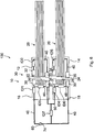
1 eine schematische Darstellung einer elektrischen Verbindungsanordnung mit einer Buchse und einem Stecker nach einem Ausführungsbeispiel der Erfindung; -
2 eine schematische Darstellung einer elektrischen Verbindungsanordnung nach einem weiteren Ausführungsbeispiel der Erfindung mit einem Kabel mit zwei Steckern, welches an zwei Buchsen angeschlossen ist; -
3 eine schematische Darstellung einer elektrischen Verbindungsanordnung mit einem Kabel mit zwei Steckern, welches an zwei Buchsen angeschlossen ist, nach einem weiteren Ausführungsbeispiel der Erfindung; -
4 eine schematische Darstellung einer elektrischen Verbindungsanordnung mit einem Kabel mit zwei Steckern, welches an zwei Buchsen angeschlossen ist, nach einem weiteren Ausführungsbeispiel der Erfindung; -
5 eine schematische Darstellung einer elektrischen Verbindungsanordnung mit zwei Buchsen und zwei Steckern nach einem weiteren Ausführungsbeispiel der Erfindung; und -
6 eine schematische Darstellung einer elektrischen Verbindungsanordnung mit zwei Buchsen und zwei Steckern nach einem weiteren Ausführungsbeispiel der Erfindung.
-
1 a schematic representation of an electrical connection arrangement with a socket and a plug according to an embodiment of the invention; -
2 a schematic representation of an electrical connection arrangement according to a further embodiment of the invention with a cable with two plugs, which is connected to two sockets; -
3 a schematic representation of an electrical connection arrangement with a cable with two plugs, which is connected to two sockets, according to a further embodiment of the invention; -
4th a schematic representation of an electrical connection arrangement with a cable with two plugs, which is connected to two sockets, according to a further embodiment of the invention; -
5 a schematic representation of an electrical connection arrangement with two sockets and two plugs according to a further embodiment of the invention; and -
6th a schematic representation of an electrical connection arrangement with two sockets and two plugs according to a further embodiment of the invention.
In den Figuren sind gleiche oder gleichartige Komponenten mit gleichen Bezugszeichen beziffert. Die Figuren zeigen lediglich Beispiele und sind nicht beschränkend zu verstehen.In the figures, the same or similar components are numbered with the same reference symbols. The figures show only examples and are not to be understood as restrictive.
Die elektrische Verbindungsanordnung
Weiter umfasst die Verbindungsanordnung
Die Überwachungseinheit
In dem Stecker
Die Überwachungseinheit
Dazu ist die Überwachungseinheit
Daraus abgeleitet kann die Überwachungseinheit
Die Identifikationskomponenten
Das Energieübertragungssystem
Die Überwachungseinheit
Die Signalgenerator der Überwachungseinheit
Eine Fehlerdetektion kann beispielsweise nach dem folgenden Entscheidungsbaum durchgeführt werden, wobei die Bezeichnung der Identifikationskomponente auch für die Bezeichnung des entsprechenden Signals verwendet wird.An error detection can be carried out, for example, according to the following decision tree, the designation of the identification component also being used for the designation of the corresponding signal.
Ist bei dem dargestellten Ausführungsbeispiel das im Empfänger detektierte Signal gleich dem durch den Signalgenerator eingespeisten Signal, bedeutet das, dass ein Kurzschluss vor der Identifikationskomponente
Kann nur das Vorhandensein der Identifikationskomponente
Kann als Signal ID1 + ID2 detektiert werden, d.h. beide Signale
Kann als Signal ID1 + ID2 + ID3 detektiert werden, liegt der Kurzschluss im Stecker
Kann als Signal ID1 + ID2 + ID3 + ID4 detektiert werden, ist die Verbindungsanordnung
Liegt das empfangene Signal konstant auf einem Wert High (beispielsweise 2 V), so liegt ein Kurzschluss gegen ein übertragenes Potential vor.If the received signal is constantly at a high value (for example 2 V), there is a short circuit to a transmitted potential.
Liegt das empfangene Signal konstant auf einem Wert Low (beispielsweise 0 V), so liegt ein Kurzschluss gegen Masse vor.If the received signal is constantly at a low value (for example 0 V), there is a short circuit to ground.
Dabei sind am jeweiligen kabelseitigen Ende der Stecker
Eine Fehlerdetektion kann beispielsweise nach dem folgenden Entscheidungsbaum durchgeführt werden, wobei die Bezeichnung der Identifikationskomponente auch für die Bezeichnung des entsprechenden Signals verwendet wird.An error detection can be carried out, for example, according to the following decision tree, the designation of the identification component also being used for the designation of the corresponding signal.
Ist bei dem dargestellten Ausführungsbeispiel das im Empfänger detektierte Signal gleich dem durch den Signalgenerator eingespeisten Signal, bedeutet das, dass ein Kurzschluss vor der Identifikationskomponente
Kann nur das Vorhandensein der Identifikationskomponente
Kann als Signal ID1 + ID2 detektiert werden, liegt der Kurzschluss im Stecker
Kann als Signal ID1 + ID2 + ID5 detektiert werden, liegt eine offene Klemme im Kabel
Kann als Signal ID1 + ID2 + (ID5 || ID6) detektiert werden, liegt eine offene Klemme in der Buchse ![]()
![]()
Kann als Signal ID1 + ID2 + (ID5 || (ID3 II ID6)) detektiert werden, liegt ein Kurzschluss im Stecker
Kann als Signal ID1 + ID2 + (ID5 || ((ID3 + ID4) II ID6)) detektiert werden, ist die Verbindungsanordnung
Liegt das empfangene Signal konstant auf einem Wert High (beispielsweise 2 V), so liegt ein Kurzschluss gegen ein übertragenes Potential vor.If the received signal is constantly at a high value (for example 2 V), there is a short circuit to a transmitted potential.
Liegt das empfangene Signal konstant auf einem Wert Low (beispielsweise 0 V), so liegt ein Kurzschluss gegen Masse vor.If the received signal is constantly at a low value (for example 0 V), there is a short circuit to ground.
In
Das Energieübertragungssystem
Das Interlocksystem
Die erste Überwachungseinheit
Die zweite Überwachungseinheit
Den Steckern
Eine Fehlerdetektion kann beispielsweise nach dem folgenden Entscheidungsbaum durchgeführt werden, wobei die Bezeichnung der Identifikationskomponente auch für die Bezeichnung des entsprechenden Signals verwendet wird.An error detection can, for example, according to the following decision tree can be carried out, whereby the designation of the identification component is also used for the designation of the corresponding signal.
Ist bei dem dargestellten Ausführungsbeispiel das im Empfänger der Überwachungseinheit
Kann nur das Vorhandensein der Identifikationskomponente
Kann als Signal ID1 + ID2 detektiert werden, ist der Kontakt von Stecker
Ist bei dem dargestellten Ausführungsbeispiel das im Empfänger der Überwachungseinheit
Kann nur das Vorhandensein der Identifikationskomponente
Kann als Signal ID3 + ID4 detektiert werden, ist der Kontakt von Stecker
Liegt das empfangene Signal konstant auf einem Wert High (beispielsweise 2 V), so liegt ein Kurzschluss gegen ein übertragenes Potential vor.If the received signal is constantly at a high value (for example 2 V), there is a short circuit to a transmitted potential.
Liegt das empfangene Signal konstant auf einem Wert Low (beispielsweise 0 V), so liegt ein Kurzschluss gegen Masse vor.If the received signal is constantly at a low value (for example 0 V), there is a short circuit to ground.
Das Energieübertragungssystem
Das Interlocksystem
Die Überwachungseinheit
Den Steckern
Eine Fehlerdetektion kann beispielsweise nach dem folgenden Entscheidungsbaum durchgeführt werden, wobei die Bezeichnung der Identifikationskomponente auch für die Bezeichnung des entsprechenden Signals verwendet wird.An error detection can be carried out, for example, according to the following decision tree, the designation of the identification component also being used for the designation of the corresponding signal.
Beinhaltet das detektierte Signal nicht ID1 + ID3 + ID2, liegt ein Kurzschluss in der Buchse
Beinhaltet das detektierte Signal nicht
Beinhaltet das detektierte Signal nicht
Beinhaltet das detektierte Signal nicht ID4 + ID5 + ID6, liegt ein Kurzschluss in der Buchse
Kann als Signal ID1 + (ID2 || ID3) + ID4 + (ID5 || ID6) detektiert werden, ist die Verbindungsanordnung
Liegt das empfangene Signal konstant auf einem Wert High (beispielsweise 2 V), so liegt ein Kurzschluss gegen ein übertragenes Potential vor.If the received signal is constantly at a high value (for example 2 V), there is a short circuit to a transmitted potential.
Liegt das empfangene Signal konstant auf einem Wert Low (beispielsweise 0 V), so liegt ein Kurzschluss gegen Masse vor.If the received signal is constantly at a low value (for example 0 V), there is a short circuit to ground.
In
Bei dieser Verbindungsanordnung
Eine Fehlerdetektion kann beispielsweise nach dem folgenden Entscheidungsbaum durchgeführt werden, wobei die Bezeichnung der Identifikationskomponente auch für die Bezeichnung des entsprechenden Signals verwendet wird.An error detection can be carried out, for example, according to the following decision tree, the designation of the identification component also being used for the designation of the corresponding signal.
Beinhaltet das detektierte Signal nicht ID1 + ID3 + ID2, liegt ein Kurzschluss in der Buchse
Beinhaltet das detektierte Signal nicht
Beinhaltet das detektierte Signal nicht
Beinhaltet das detektierte Signal nicht ID4 + ID5 + ID6, liegt ein Kurzschluss in der Buchse
Kann als Signal ID1 + (ID2 || ID3) + ID7 || (ID4 + (ID5) || ID6)) detektiert werden, ist die Verbindungsanordnung
Liegt das empfangene Signal konstant auf einem Wert High (beispielsweise 2 V), so liegt ein Kurzschluss gegen ein übertragenes Potential vor.If the received signal is constantly at a high value (for example 2 V), there is a short circuit to a transmitted potential.
Liegt das empfangene Signal konstant auf einem Wert Low (beispielsweise 0 V), so liegt ein Kurzschluss gegen Masse vor.If the received signal is constantly at a low value (for example 0 V), there is a short circuit to ground.
BezugszeichenlisteList of reference symbols
- 1010
- EnergieübertragungssystemEnergy transmission system
- 1212th
- Steckerplug
- 1414th
- Steckerplug
- 1616
- BuchseRifle
- 1818th
- BuchseRifle
- 2020th
- Kabelcable
- 2222nd
- Haupt-SteckerkontaktMain plug contact
- 2424
- Haupt-SteckerkontaktMain plug contact
- 2626th
- Haupt-BuchsenkontaktMain socket contact
- 2828
- Haupt-BuchsenkontaktMain socket contact
- 3030th
- InterlocksystemInterlock system
- 3232
- Interlock-SteckerkontaktInterlock plug contact
- 3333
- Interlock-SteckerkontaktInterlock plug contact
- 3434
- Interlock-SteckerkontaktInterlock plug contact
- 3535
- Interlock-SteckerkontaktInterlock plug contact
- 3636
- Interlock-BuchsenkontaktInterlock socket contact
- 3737
- Interlock-BuchsenkontaktInterlock socket contact
- 3838
- Interlock-BuchsenkontaktInterlock socket contact
- 3939
- Interlock-BuchsenkontaktInterlock socket contact
- 4040
- RingleitungRing line
- 4141
- RingleitungRing line
- 4242
- VerbindungsleitungConnecting line
- 4444
- VerbindungsleitungConnecting line
- 4646
- VerbindungsleitungConnecting line
- 4848
- VerbindungsleitungConnecting line
- 5050
- VerbindungsleitungConnecting line
- 6060
- ÜberwachungseinheitMonitoring unit
- 6262
- ÜberwachungseinheitMonitoring unit
- 7070
- Leitungmanagement
- 7272
- Leitungmanagement
- 7474
- Anschlussconnection
- 100100
- EnergiespeichersystemEnergy storage system
- ID1ID1
- IdentifikationskomponenteIdentification component
- ID2ID2
- IdentifikationskomponenteIdentification component
- ID3ID3
- IdentifikationskomponenteIdentification component
- ID4ID4
- IdentifikationskomponenteIdentification component
- ID5ID5
- IdentifikationskomponenteIdentification component
- ID6ID6
- IdentifikationskomponenteIdentification component
- ID7ID7
- IdentifikationskomponenteIdentification component
ZITATE ENTHALTEN IN DER BESCHREIBUNGQUOTES INCLUDED IN THE DESCRIPTION
Diese Liste der vom Anmelder aufgeführten Dokumente wurde automatisiert erzeugt und ist ausschließlich zur besseren Information des Lesers aufgenommen. Die Liste ist nicht Bestandteil der deutschen Patent- bzw. Gebrauchsmusteranmeldung. Das DPMA übernimmt keinerlei Haftung für etwaige Fehler oder Auslassungen.This list of the documents listed by the applicant was generated automatically and is included solely for the better information of the reader. The list is not part of the German patent or utility model application. The DPMA assumes no liability for any errors or omissions.
Zitierte PatentliteraturPatent literature cited
- DE 102019002307 A1 [0003]DE 102019002307 A1 [0003]
Claims (10)
Priority Applications (1)
| Application Number | Priority Date | Filing Date | Title |
|---|---|---|---|
| DE102021003652.2A DE102021003652A1 (en) | 2021-07-15 | 2021-07-15 | Electrical connector assembly and method of monitoring operation of an electrical connector assembly |
Applications Claiming Priority (1)
| Application Number | Priority Date | Filing Date | Title |
|---|---|---|---|
| DE102021003652.2A DE102021003652A1 (en) | 2021-07-15 | 2021-07-15 | Electrical connector assembly and method of monitoring operation of an electrical connector assembly |
Publications (1)
| Publication Number | Publication Date |
|---|---|
| DE102021003652A1 true DE102021003652A1 (en) | 2021-11-04 |
Family
ID=78267671
Family Applications (1)
| Application Number | Title | Priority Date | Filing Date |
|---|---|---|---|
| DE102021003652.2A Withdrawn DE102021003652A1 (en) | 2021-07-15 | 2021-07-15 | Electrical connector assembly and method of monitoring operation of an electrical connector assembly |
Country Status (1)
| Country | Link |
|---|---|
| DE (1) | DE102021003652A1 (en) |
Cited By (1)
| Publication number | Priority date | Publication date | Assignee | Title |
|---|---|---|---|---|
| DE102022002083B3 (en) | 2022-06-10 | 2023-10-05 | Mercedes-Benz Group AG | Method for monitoring the operation of a connection arrangement between interlock components and interlock component for use in an interlock loop |
Citations (1)
| Publication number | Priority date | Publication date | Assignee | Title |
|---|---|---|---|---|
| DE102019002307A1 (en) | 2019-03-29 | 2019-11-14 | Daimler Ag | Electrical connection arrangement |
-
2021
- 2021-07-15 DE DE102021003652.2A patent/DE102021003652A1/en not_active Withdrawn
Patent Citations (1)
| Publication number | Priority date | Publication date | Assignee | Title |
|---|---|---|---|---|
| DE102019002307A1 (en) | 2019-03-29 | 2019-11-14 | Daimler Ag | Electrical connection arrangement |
Cited By (1)
| Publication number | Priority date | Publication date | Assignee | Title |
|---|---|---|---|---|
| DE102022002083B3 (en) | 2022-06-10 | 2023-10-05 | Mercedes-Benz Group AG | Method for monitoring the operation of a connection arrangement between interlock components and interlock component for use in an interlock loop |
Similar Documents
| Publication | Publication Date | Title |
|---|---|---|
| DE10308604B4 (en) | Device and method for detecting incorrect fastener insertion and program for executing the method | |
| DE68908123T2 (en) | PORTABLE IDENTIFIER FOR COMMUNICATION CABLES. | |
| DE102012105631B4 (en) | High voltage (HV) safety interlock for HV components in a vehicle | |
| EP2817976B1 (en) | Battery sensor data transmission unit and a method for transmitting battery sensor data | |
| EP1044851B1 (en) | Apparatus for a power ring | |
| DE112020001101T5 (en) | LOCKING DEVICE FOR HIGH VOLTAGE DEVICES | |
| DE102016111690A1 (en) | Power distributor for a vehicle | |
| WO2013076087A1 (en) | Test system and test method for cable harnesses | |
| EP2920059B1 (en) | Boat with high voltage system | |
| EP2817975B1 (en) | Battery sensor data transmission unit and method for battery sensor data transmission | |
| DE102017107277A1 (en) | Arrangement and method for updating a control software in a high-voltage control unit | |
| DE102016105747B4 (en) | Concept for detecting a decoupling of a first plug part of an electrical connector from a second plug part of the electrical connector | |
| DE19826028B4 (en) | Device for monitoring a cable used in a vehicle | |
| DE102016115807A1 (en) | Adapter for a battery management system and battery management system | |
| WO2013072028A2 (en) | Method and device for monitoring a high-voltage arrangement | |
| DE102011117248A1 (en) | Method for monitoring high voltage components of electrical system of electrical vehicle, involves checking plug connections automatically to obtain plug connector test result, and comparing result with cable set test result | |
| DE102021003652A1 (en) | Electrical connector assembly and method of monitoring operation of an electrical connector assembly | |
| DE102018126787B4 (en) | Charging station for electric vehicles with at least two charging connections and an optional power electronics unit that can be switched to this | |
| EP3503313B1 (en) | Multi-battery adapter for establishing an electrical connection between at least two traction batteries on the one hand and a drive unit of an electrical bicycle on the other | |
| WO2013091745A1 (en) | Current sensor | |
| DE102006016137A1 (en) | Plug-in device for contacting the high-voltage module of a hybrid vehicle and high-voltage module of a hybrid vehicle | |
| DE102014206925A1 (en) | Motor vehicle electrical system and method for detecting an arc in a motor vehicle electrical system | |
| DE102019217783A1 (en) | Apparatus and method for charging a number of electrically powered motor vehicles | |
| DE102018111536B3 (en) | Method for controlling a charging process of an electric vehicle and charging cable | |
| DE102019004206A1 (en) | Charging system for an electrically operated vehicle |
Legal Events
| Date | Code | Title | Description |
|---|---|---|---|
| R230 | Request for early publication | ||
| R081 | Change of applicant/patentee |
Owner name: MERCEDES-BENZ GROUP AG, DE Free format text: FORMER OWNER: DAIMLER AG, STUTTGART, DE |
|
| R119 | Application deemed withdrawn, or ip right lapsed, due to non-payment of renewal fee |