DE102021003163A1 - fastening system - Google Patents
fastening system Download PDFInfo
- Publication number
- DE102021003163A1 DE102021003163A1 DE102021003163.6A DE102021003163A DE102021003163A1 DE 102021003163 A1 DE102021003163 A1 DE 102021003163A1 DE 102021003163 A DE102021003163 A DE 102021003163A DE 102021003163 A1 DE102021003163 A1 DE 102021003163A1
- Authority
- DE
- Germany
- Prior art keywords
- housing
- ion exchanger
- container
- containers
- exchange resin
- Prior art date
- Legal status (The legal status is an assumption and is not a legal conclusion. Google has not performed a legal analysis and makes no representation as to the accuracy of the status listed.)
- Ceased
Links
- 150000002500 ions Chemical class 0.000 claims abstract description 36
- 239000003463 adsorbent Substances 0.000 claims abstract description 24
- NWUYHJFMYQTDRP-UHFFFAOYSA-N 1,2-bis(ethenyl)benzene;1-ethenyl-2-ethylbenzene;styrene Chemical compound C=CC1=CC=CC=C1.CCC1=CC=CC=C1C=C.C=CC1=CC=CC=C1C=C NWUYHJFMYQTDRP-UHFFFAOYSA-N 0.000 claims abstract description 20
- 239000003729 cation exchange resin Substances 0.000 claims abstract description 14
- 239000000446 fuel Substances 0.000 claims abstract description 10
- 239000002826 coolant Substances 0.000 claims abstract description 8
- 150000001450 anions Chemical class 0.000 claims abstract description 7
- 239000012528 membrane Substances 0.000 claims abstract description 6
- 239000003957 anion exchange resin Substances 0.000 claims description 13
- 239000002253 acid Substances 0.000 claims description 9
- 239000012530 fluid Substances 0.000 claims description 4
- 238000001816 cooling Methods 0.000 claims description 2
- 239000003456 ion exchange resin Substances 0.000 abstract description 8
- 229920003303 ion-exchange polymer Polymers 0.000 abstract description 8
- 230000008929 regeneration Effects 0.000 abstract description 8
- 238000011069 regeneration method Methods 0.000 abstract description 8
- 101100298225 Caenorhabditis elegans pot-2 gene Proteins 0.000 description 4
- 239000004033 plastic Substances 0.000 description 4
- 239000004952 Polyamide Substances 0.000 description 3
- 229920002647 polyamide Polymers 0.000 description 3
- 239000000126 substance Substances 0.000 description 3
- OKTJSMMVPCPJKN-UHFFFAOYSA-N Carbon Chemical compound [C] OKTJSMMVPCPJKN-UHFFFAOYSA-N 0.000 description 2
- 239000003795 chemical substances by application Substances 0.000 description 2
- 230000001419 dependent effect Effects 0.000 description 2
- 230000000694 effects Effects 0.000 description 2
- 238000001914 filtration Methods 0.000 description 2
- 238000005342 ion exchange Methods 0.000 description 2
- 239000000203 mixture Substances 0.000 description 2
- 239000002245 particle Substances 0.000 description 2
- 239000011347 resin Substances 0.000 description 2
- 229920005989 resin Polymers 0.000 description 2
- BUHVIAUBTBOHAG-FOYDDCNASA-N (2r,3r,4s,5r)-2-[6-[[2-(3,5-dimethoxyphenyl)-2-(2-methylphenyl)ethyl]amino]purin-9-yl]-5-(hydroxymethyl)oxolane-3,4-diol Chemical compound COC1=CC(OC)=CC(C(CNC=2C=3N=CN(C=3N=CN=2)[C@H]2[C@@H]([C@H](O)[C@@H](CO)O2)O)C=2C(=CC=CC=2)C)=C1 BUHVIAUBTBOHAG-FOYDDCNASA-N 0.000 description 1
- 239000004743 Polypropylene Substances 0.000 description 1
- 229910021536 Zeolite Inorganic materials 0.000 description 1
- 229910052782 aluminium Inorganic materials 0.000 description 1
- XAGFODPZIPBFFR-UHFFFAOYSA-N aluminium Chemical compound [Al] XAGFODPZIPBFFR-UHFFFAOYSA-N 0.000 description 1
- 229940023913 cation exchange resins Drugs 0.000 description 1
- 150000001768 cations Chemical class 0.000 description 1
- 239000000356 contaminant Substances 0.000 description 1
- 239000012809 cooling fluid Substances 0.000 description 1
- HNPSIPDUKPIQMN-UHFFFAOYSA-N dioxosilane;oxo(oxoalumanyloxy)alumane Chemical compound O=[Si]=O.O=[Al]O[Al]=O HNPSIPDUKPIQMN-UHFFFAOYSA-N 0.000 description 1
- 239000007788 liquid Substances 0.000 description 1
- 229910052751 metal Inorganic materials 0.000 description 1
- 239000002184 metal Substances 0.000 description 1
- 238000000034 method Methods 0.000 description 1
- -1 polypropylene Polymers 0.000 description 1
- 229920001155 polypropylene Polymers 0.000 description 1
- 238000002360 preparation method Methods 0.000 description 1
- 238000000926 separation method Methods 0.000 description 1
- 239000010457 zeolite Substances 0.000 description 1
Images
Classifications
-
- H—ELECTRICITY
- H01—ELECTRIC ELEMENTS
- H01M—PROCESSES OR MEANS, e.g. BATTERIES, FOR THE DIRECT CONVERSION OF CHEMICAL ENERGY INTO ELECTRICAL ENERGY
- H01M8/00—Fuel cells; Manufacture thereof
- H01M8/04—Auxiliary arrangements, e.g. for control of pressure or for circulation of fluids
- H01M8/04007—Auxiliary arrangements, e.g. for control of pressure or for circulation of fluids related to heat exchange
- H01M8/04044—Purification of heat exchange media
-
- B—PERFORMING OPERATIONS; TRANSPORTING
- B01—PHYSICAL OR CHEMICAL PROCESSES OR APPARATUS IN GENERAL
- B01J—CHEMICAL OR PHYSICAL PROCESSES, e.g. CATALYSIS OR COLLOID CHEMISTRY; THEIR RELEVANT APPARATUS
- B01J47/00—Ion-exchange processes in general; Apparatus therefor
- B01J47/02—Column or bed processes
- B01J47/026—Column or bed processes using columns or beds of different ion exchange materials in series
- B01J47/028—Column or bed processes using columns or beds of different ion exchange materials in series with alternately arranged cationic and anionic exchangers
Landscapes
- Chemical & Material Sciences (AREA)
- Chemical Kinetics & Catalysis (AREA)
- Organic Chemistry (AREA)
- Life Sciences & Earth Sciences (AREA)
- Engineering & Computer Science (AREA)
- Manufacturing & Machinery (AREA)
- Sustainable Development (AREA)
- Sustainable Energy (AREA)
- Electrochemistry (AREA)
- General Chemical & Material Sciences (AREA)
- Treatment Of Water By Ion Exchange (AREA)
Abstract
Die Erfindung betrifft einen lonentauscher für ein Kühlmittelsystem einer Brennstoffzelle aufweisend einen in das Volumen des Gehäuses eingesetzten Behälter aufweisend ein Anionen- oder ein Kationentauscherharz und mindestens einen weiteren in das Volumen des Gehäuses eingesetzten Behälter aufweisend ein weiteres Adsorptionsmittel, wobei mindestens einer der Behälter eine flexible fluiddurchlässige Hülle, insbesondere eine Membran, aufweist. Hiermit ist es erstmalig möglich einen lonentauscher mit standardisierten lonentauscherharzbehältern zu befüllen und im Servicefall nur die verbrauchten lonentauscherharzbehälter für eine Regeneration auszutauschen.The invention relates to an ion exchanger for a coolant system of a fuel cell, having a container inserted into the volume of the housing, having an anion or a cation exchange resin and at least one other container inserted into the volume of the housing, having a further adsorbent, with at least one of the containers having a flexible, fluid-permeable Cover, in particular a membrane. This makes it possible for the first time to fill an ion exchanger with standardized ion exchange resin tanks and, in the event of a service, to only replace the used ion exchange resin tank for regeneration.
Description
Die vorliegende Erfindung betrifft einen lonentauscher für ein Kühlmittelsystem einer Brennstoffzelle gemäß dem Oberbegriff des Anspruchs 1.The present invention relates to an ion exchanger for a coolant system of a fuel cell according to the preamble of claim 1.
Die
Die vorliegende Erfindung beschäftigt sich daher mit dem Problem, für einen Ionentauscher für ein Kühlmittelsystem einer Brennstoffzelle der gattungsgemäßen Art eine verbesserte oder zumindest eine alternative Ausführungsform anzugeben, insbesondere einen lonentauscher mit mindestens zwei separaten Behältern für das lonentauscherharz bereitzustellen, welche sich zudem an die Form des Gehäuses des lonentauschers anpasst und im Servicefall einzeln aus dem Gehäuse des Ionentauschers entnehmbar und regenerierbar sind.The present invention is therefore concerned with the problem of specifying an improved or at least an alternative embodiment for an ion exchanger for a coolant system of a fuel cell of the generic type, in particular to provide an ion exchanger with at least two separate containers for the ion exchange resin, which also adapt to the shape of the Adjusts the housing of the ion exchanger and can be individually removed and regenerated from the housing of the ion exchanger in the event of service.
Dieses Problem wird erfindungsgemäß durch den Gegenstand des unabhängigen Anspruchs 1 gelöst. Vorteilhafte Ausführungsformen sind Gegenstand der abhängigen Ansprüche.According to the invention, this problem is solved by the subject matter of independent claim 1 . Advantageous embodiments are the subject matter of the dependent claims.
Die vorliegende Erfindung beruht auf dem allgemeinen Gedanken, einen lonentauscher für ein Kühlmittelsystem einer Brennstoffzelle mit mindestens zwei Behältern auszustatten, wovon mindestens ein Behälter eine flexible, fluiddurchlässige Hülle, insbesondere eine Membran aufweist. In einer bevorzugten Ausführungsform sind mindestens zwei Behälter mit einer flexiblen, fluiddurchlässigen Hülle und in einer besonders bevorzugten Ausführung alle verwendeten Behälter mit einer flexiblen, fluiddurchlässigen Hülle ausgestattet. Die Hülle besteht aus einem kühlmittelbeständigen Kunststoff, insbesondere aus Polypropylen oder Polyamid. In einer bevorzugten Ausgestaltung ist die Hülle als Membran ausgestaltet und hat eine zusätzliche Partikelfiltrationswirkung und besteht aus einem Kunststoff. Durch die Partikelfiltrationswirkung der Membran kann ein im Behälter angeordnetes Adsorptionsmittel eine längere Standzeit erzielen, da mögliche Verunreinigungen vom Adsorptionsmittel ferngehalten werden.The present invention is based on the general idea of equipping an ion exchanger for a coolant system of a fuel cell with at least two containers, of which at least one container has a flexible, fluid-permeable shell, in particular a membrane. In a preferred embodiment, at least two containers are equipped with a flexible, fluid-permeable cover, and in a particularly preferred embodiment, all of the containers used are equipped with a flexible, fluid-permeable cover. The shell consists of a coolant-resistant plastic, in particular polypropylene or polyamide. In a preferred embodiment, the shell is designed as a membrane and has an additional particle filtration effect and consists of a plastic. Due to the particle filtration effect of the membrane, an adsorbent arranged in the container can achieve a longer service life, since possible contaminants are kept away from the adsorbent.
Hierfür weist der lonentauscher ein Gehäuse, welches in einen Gehäusetopf und einen Gehäusedeckel aufgeteilt ist, auf. Der Gehäusetopf besteht aus einem Metall, insbesondere aus Aluminium. In einer alternativen Ausführungsform kann der Gehäusetopf aus Kunststoff, insbesondere aus Polyamid bestehen. Der Gehäusedeckel besteht aus einem Kunstsoff, insbesondere aus einem Polyamid. Der Gehäusedeckel wird für einen ordnungsgemäßen Betrieb mit dem Gehäusetopf gekoppelt, insbesondere mit diesem verschraubt oder über eine Bayonettverbindung miteinander verbunden. Der gekoppelte Gehäusedeckel und der Gehäusetopf bilden ein Volumen. Das Volumen des lonentauschers dient zur Aufnahme von mindestens zwei Behältern. Die Behälter weisen eine fluiddurchlässige Hülle auf, die derart gestaltet ist, dass ein darin eingeschlossenes Adsorptionsmittel im Betrieb des lonentauschers eingeschlossen bleibt. Das Adsorptionsmittel ist ein lonentauscher, insbesondere ein Anionen- oder Kationentauscher, ein Zeolith oder Aktivkohle. Mindestens ein Behälter weist eine flexible Hülle auf, womit es möglich ist, dass der mindestens eine Behälter sich an die Kontur des Gehäuses anpasst. In einer bevorzugten Ausgestaltung sind beide Behälter mit einer flexiblen Hülle ausgestaltet, womit sich der erste Behälter an die Kontur des Gehäuses anpasst und der weitere Behälter sich an die Kontur des ersten Behälters und an die Kontur des Gehäuses anpasst. Hiermit ist es erstmals möglich den zweiten oder weiteren Behälter auch als Verspannung für den ersten Behälter zu nutzen. Durch die Verspannung des ersten Behälters im Gehäuse wird das Adsorptionsmittel im Behälter in Form gehalten, so dass sich keine unerwünschten Strömungswege durch das Adsorptionsmittel ergibt und das Adsorptionsmittel nicht gleichmäßig durchströmt wird. Durch die Verspannung im Gehäuse wird daher die Wirksamkeit des Adsorptionsmittels erhöht.For this purpose, the ion exchanger has a housing which is divided into a housing pot and a housing cover. The housing pot consists of a metal, in particular aluminum. In an alternative embodiment, the housing pot can be made of plastic, in particular made of polyamide. The housing cover consists of a plastic, in particular a polyamide. For proper operation, the housing cover is coupled to the housing pot, in particular screwed to it or connected to one another via a bayonet connection. The coupled housing cover and the housing pot form one volume. The volume of the ion exchanger serves to accommodate at least two containers. The containers have a fluid-permeable shell which is designed in such a way that an adsorbent enclosed therein remains enclosed during operation of the ion exchanger. The adsorbent is an ion exchanger, in particular an anion or cation exchanger, a zeolite or activated carbon. At least one container has a flexible cover, which makes it possible for the at least one container to adapt to the contour of the housing. In a preferred embodiment, both containers are designed with a flexible cover, with which the first container adapts to the contour of the housing and the other container adapts to the contour of the first container and the contour of the housing. This makes it possible for the first time to use the second or further container as a brace for the first container. The bracing of the first container in the housing keeps the shape of the adsorbent in the container, so that there are no undesired flow paths through the adsorbent and the flow through the adsorbent is not uniform. The effectiveness of the adsorbent is therefore increased by the tension in the housing.
Das Adsorptionsmittel ist in einer bevorzugten Ausführungsform ein Anionentauscherharz oder ein Kationentauscherharz. Für eine spätere Regeneration der Harze ist es dabei wichtig, dass die Behälter nicht mit einer Mischung aus einem Anionen- und einem Kationentauscherharz befüllt sind, sondern entweder mit Anionentauscherharz oder mit Kationentauscherharz.In a preferred embodiment, the adsorbent is an anion exchange resin or a cation exchange resin. For later regeneration of the resins, it is important that the containers are not filled with a mixture of an anion and cation exchange resin, but with either anion exchange resin or cation exchange resin.
Sofern eine Regeneration des Adsorptionsmittels angedacht ist, muss die Hülle der Behälter beständig gegen das Regenerationsmittel, insbesondere gegenüber einer Starken Säure, insbesondere einer Säure mit einem pKs-Wert von maximal 9, bei einem Anionentauscherharz und einer starken Lauge, insbesondere einer Lauge mit einem pKb-Wert von maximal 10, bei einem Kationentauscherharz sein. Der lonentauscher weist des Weiteren mindestens einen Zulauf und mindestens einen Ablauf auf. In einer bevorzugten Ausführung ist der Zulauf am Gehäusetopf und der Ablauf am Gehäusedeckel angeordnet.If a regeneration of the adsorbent is considered, the shell of the container must be resistant to the regeneration agent, in particular be more opposite to a strong acid, in particular an acid with a pKa value of not more than 9, in an anion exchange resin and a strong base, in particular a base with a pKb value of not more than 10, in the case of a cation exchange resin. The ion exchanger also has at least one inlet and at least one outlet. In a preferred embodiment, the inlet is arranged on the housing pot and the outlet on the housing cover.
Der pKs-Wert ist eine spezifische Stoffgröße und wird unter anderem auch als Säurekonstante bezeichnet. Jede Säure hat einen für die jeweilige Säure spezifischen pKs-Wert, welche die Stärke der Säure beschreibt. Je kleiner der pKs-Wert ist, desto stärker ist die Säure. Der pKb-Wert ist eine spezifische Stoffgröße für Laugen. Jede Lauge weist einen für die jeweilige Lauge spezifischen pKb-Wert auf, welcher die Stärke der Lauge beschreibt. Je kleiner der pKb-Wert ist, desto stärker ist die Lauge.The pKa value is a specific substance variable and is also referred to as the acidity constant. Each acid has a pKa value specific to that acid, which describes the strength of the acid. The smaller the pKa value, the stronger the acid. The pKb value is a specific substance size for alkalis. Each lye has a pKb value specific to that lye, which describes the strength of the lye. The lower the pKb value, the stronger the lye.
Durch die Ausgestaltung der Behältnisse in gleichen geometrischen Abmessungen kann ein in den Maßen standardisiertes Produkt bereitgestellt werden, womit es möglich ist, die Behältnisse auf einfache Weise in Massenproduktion herzustellen. Zudem ist es hiermit erstmalig möglich, dass das Volumen des Gehäuses eines lonentauschers mit mehreren gleichen Behältern befüllt wird anstelle eines extra für dieses System angepassten Behälters. Dies erleichtert die Adaptierung auf neue Systeme, da die Adsorptionsmittelbehältnisse für verschiedene Anwendungsfälle nicht modifiziert werden müssen.By configuring the containers with the same geometric dimensions, a dimensionally standardized product can be provided, with which it is possible to mass-produce the containers in a simple manner. In addition, it is hereby possible for the first time that the volume of the housing of an ion exchanger is filled with several identical containers instead of a container specially adapted for this system. This makes it easier to adapt to new systems, since the adsorbent containers do not have to be modified for different applications.
Sofern unterschiedlich chemische Adsorber benötigt werden, können für die verschiedenen Anwendungsfälle die Adsorbtionsmittelbehältnisse markiert werden, insbesondere mit einer Farbe, in einer besonders bevorzugten Ausführungsform mit einer roten Farbe, markiert werden. Hiermit ist es möglich die einzelnen Behälter der Adsorbtionsmittel zu unterscheiden, was insbesondere für die Regeneration wichtig ist.If different chemical adsorbers are required, the adsorbent containers can be marked for the different applications, in particular marked with a color, in a particularly preferred embodiment with a red color. This makes it possible to differentiate between the individual adsorbent containers, which is particularly important for regeneration.
Weitere wichtige Merkmale und Vorteile der Erfindung ergeben sich aus den Unteransprüchen, aus den Zeichnungen und aus der zugehörigen Figurenbeschreibung anhand der Zeichnungen.Further important features and advantages of the invention result from the dependent claims, from the drawings and from the associated description of the figures with reference to the drawings.
Es versteht sich, dass die vorstehend genannten und die nachstehend noch zu erläuternden Merkmale nicht nur in der jeweils angegebenen Kombination, sondern auch in anderen Kombinationen oder in Alleinstellung verwendbar sind, ohne den Rahmen der vorliegenden Erfindung zu verlassen.It goes without saying that the features mentioned above and those still to be explained below can be used not only in the combination specified in each case, but also in other combinations or on their own, without departing from the scope of the present invention.
Bevorzugte Ausführungsbeispiele der Erfindung sind in den Zeichnungen dargestellt und werden in der nachfolgenden Beschreibung näher erläutert, wobei sich gleiche Bezugszeichen auf gleiche oder ähnliche oder funktional gleiche Komponenten beziehen.Preferred exemplary embodiments of the invention are illustrated in the drawings and are explained in more detail in the following description, with the same reference symbols referring to identical or similar or functionally identical components.
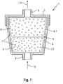
Es zeigt, jeweils schematisch
-
1 eine schematische Ansicht eines erfindungsgemäßen lonentauschers
-
1 a schematic view of an ion exchanger according to the invention
Entsprechend der
Das Adsorptionsmittel 7 ist in einer bevorzugten Ausführungsform ein Anionentauscherharz oder ein Kationentauscherharz. Für eine spätere Regeneration der Harze ist es dabei wichtig, dass die Behälter 5, 6 nicht mit einer Mischung aus einem Anionen- und einem Kationentauscherharz befüllt sind, sondern entweder mit Anionentauscherharz oder mit Kationentauscherharz.In a preferred embodiment, the adsorbent 7 is an anion exchange resin or a cation exchange resin. For a later regeneration of the resins it is important that the
Sofern eine Regeneration des Adsorptionsmittels angedacht ist, muss die Hülle 5.1, 6.1 der Behälter 5, 6 beständig gegen das Regenerationsmittel, insbesondere gegenüber einer Starken Säure, insbesondere einer Säure mit einem pKs-Wert von maximal 9, bei einem Anionentauscherharz und einer starken Lauge, insbesondere einer Lauge mit einem pKb-Wert von maximal 10, bei einem Kationentauscherharz sein.If regeneration of the adsorbent is planned, the shell 5.1, 6.1 of the
Der lonentauscher 1 weist des Weiteren einen Zulauf 8 am Gehäusetopf 2 und einen Ablauf 9 am Gehäusedeckel auf. Der Pfeil 10 zeigt exemplarisch die Zulaufströmung über den Zulauf 8 in den lonentauscher 1 und der Pfeil 11 zeigt exemplarisch die Ablaufströmung aus dem lonentauscher 1 über den Ablauf 9, der am Gehäusedeckel 3 angeordnet ist.The ion exchanger 1 also has an
BezugszeichenlisteReference List
- 11
- lonentauscherion exchanger
- 22
- Gehäusetopfhousing pot
- 33
- Gehäusedeckelhousing cover
- 44
- Volumen des Gehäusesvolume of the case
- 55
- Erster BehälterFirst container
- 5.15.1
- Hülle des ersten BehältersShell of the first container
- 66
- Weiterer BehälterAnother container
- 6.16.1
- Hülle des weiteren BehältersShell of the other container
- 77
- Adsorptionsmitteladsorbent
- 88th
- ZulaufIntake
- 99
- Ablaufprocess
- 1010
- Pfeil zur exemplarischen Darstellung der ZulaufströmungArrow for example representation of the inflow
- 1111
- Pfeil zur exemplarischen Darstellung der AblaufströmungArrow for exemplary representation of the discharge flow
ZITATE ENTHALTEN IN DER BESCHREIBUNGQUOTES INCLUDED IN DESCRIPTION
Diese Liste der vom Anmelder aufgeführten Dokumente wurde automatisiert erzeugt und ist ausschließlich zur besseren Information des Lesers aufgenommen. Die Liste ist nicht Bestandteil der deutschen Patent- bzw. Gebrauchsmusteranmeldung. Das DPMA übernimmt keinerlei Haftung für etwaige Fehler oder Auslassungen.This list of the documents cited by the applicant was generated automatically and is included solely for the better information of the reader. The list is not part of the German patent or utility model application. The DPMA assumes no liability for any errors or omissions.
Zitierte PatentliteraturPatent Literature Cited
- DE 102011009917 A1 [0002]DE 102011009917 A1 [0002]
Claims (12)
Priority Applications (1)
| Application Number | Priority Date | Filing Date | Title |
|---|---|---|---|
| DE102021003163.6A DE102021003163A1 (en) | 2021-06-18 | 2021-06-18 | fastening system |
Applications Claiming Priority (1)
| Application Number | Priority Date | Filing Date | Title |
|---|---|---|---|
| DE102021003163.6A DE102021003163A1 (en) | 2021-06-18 | 2021-06-18 | fastening system |
Publications (1)
| Publication Number | Publication Date |
|---|---|
| DE102021003163A1 true DE102021003163A1 (en) | 2022-12-22 |
Family
ID=84283708
Family Applications (1)
| Application Number | Title | Priority Date | Filing Date |
|---|---|---|---|
| DE102021003163.6A Ceased DE102021003163A1 (en) | 2021-06-18 | 2021-06-18 | fastening system |
Country Status (1)
| Country | Link |
|---|---|
| DE (1) | DE102021003163A1 (en) |
Citations (2)
| Publication number | Priority date | Publication date | Assignee | Title |
|---|---|---|---|---|
| DE102011009917A1 (en) | 2011-01-31 | 2012-08-02 | Mann + Hummel Gmbh | Expansion tank for liquid fluid and ion exchanger of a surge tank |
| DE202015007200U1 (en) | 2014-04-10 | 2016-01-13 | Unger Marketing International, Llc | Clean water systems |
-
2021
- 2021-06-18 DE DE102021003163.6A patent/DE102021003163A1/en not_active Ceased
Patent Citations (2)
| Publication number | Priority date | Publication date | Assignee | Title |
|---|---|---|---|---|
| DE102011009917A1 (en) | 2011-01-31 | 2012-08-02 | Mann + Hummel Gmbh | Expansion tank for liquid fluid and ion exchanger of a surge tank |
| DE202015007200U1 (en) | 2014-04-10 | 2016-01-13 | Unger Marketing International, Llc | Clean water systems |
Similar Documents
| Publication | Publication Date | Title |
|---|---|---|
| DE10327988B4 (en) | Filter module for the treatment of liquids | |
| DE2737039A1 (en) | DEVICE FOR DISTRIBUTING AND COLLECTING FLUID IN OPPOSITE DIRECTIONS WITH DIFFERENT FLOW SPEEDS | |
| DE102007056675A1 (en) | motor vehicle | |
| DE2155454A1 (en) | Process for coating a filter candle with a granular filter aid and filter candle for carrying out this process | |
| DE2621953A1 (en) | DEVICE FOR CONTACTING LIQUIDS WITH SOLIDS | |
| EP4504368A1 (en) | Ring filter element | |
| DE8111288U1 (en) | "DEVICE FOR IMPLEMENTING PROCESS PROCESSES" | |
| DE102007033339A1 (en) | Filter cartridge for water filter device e.g. household water filter, comprises housing with upper part including inlet and lower part, which is filled with filtering medium and includes outlet, means for reversing flow, and two chambers | |
| WO2019224033A1 (en) | Phase separating device | |
| DE102021003163A1 (en) | fastening system | |
| EP0971778A1 (en) | Method for exchanging materials between two liquid phases | |
| DE102011004081A1 (en) | filtering device | |
| DE102021003089A1 (en) | ion exchanger | |
| DE4131792C1 (en) | Ion exchanger regeneration for dishwasher softener - by removing water from ion exchanger, introducing brine into container, and regenerating in part of programme, for improved effect | |
| DE102015014282A1 (en) | Water separator and Wasserabscheidesystem clamped between two end plates held Endabscheidesieb | |
| DE102004057631A1 (en) | Fuel supply unit for motor vehicle's internal combustion engine has ion exchange means installed inside chamber charged with fuel for removal of salts such as calcium carbonate soluble in water components of fuel | |
| DE102018006738B4 (en) | Device for dispersion adhesive waste | |
| DE102011119986A1 (en) | Liquid filter and filter element with an additive container | |
| DE8715856U1 (en) | Valve | |
| DE102011119988A1 (en) | Liquid filter for internal combustion engine of motor vehicle, has receptacle with through-flow openings for fluid connecting receiving compartment of liquid additive receptacle having region of interior space outside receptacle | |
| DE102008034629A1 (en) | Storage container fastening system for lorry, has console elements for accommodation of storage containers and selectively directly or indirectly fixed at side members by connection element, where elements have screwing openings | |
| DE69408730T2 (en) | Liquid distribution and dispensing device in a water treatment unit | |
| DE2347690A1 (en) | PROCESS FOR THE RECOVERY TREATMENT OF WASTE WATER DURING CHROME PLATING | |
| DE202024104396U1 (en) | Ion exchange filter assembly and connecting pipe | |
| DE1915913A1 (en) | Regenerating mixed-bed ion-exchange resins |
Legal Events
| Date | Code | Title | Description |
|---|---|---|---|
| R012 | Request for examination validly filed | ||
| R016 | Response to examination communication | ||
| R002 | Refusal decision in examination/registration proceedings | ||
| R003 | Refusal decision now final |