DE102020212740A1 - CONNECTOR WITH A HOLDING ELEMENT FOR HOLDING AN ELECTRICALLY CONDUCTIVE ELEMENT - Google Patents

CONNECTOR WITH A HOLDING ELEMENT FOR HOLDING AN ELECTRICALLY CONDUCTIVE ELEMENT Download PDF

Info

Publication number
DE102020212740A1
DE102020212740A1 DE102020212740.9A DE102020212740A DE102020212740A1 DE 102020212740 A1 DE102020212740 A1 DE 102020212740A1 DE 102020212740 A DE102020212740 A DE 102020212740A DE 102020212740 A1 DE102020212740 A1 DE 102020212740A1
Authority
DE
Germany
Prior art keywords
connector
electrically conductive
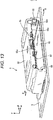
housing
mating
holding
Prior art date
Legal status (The legal status is an assumption and is not a legal conclusion. Google has not performed a legal analysis and makes no representation as to the accuracy of the status listed.)
Pending
Application number
DE102020212740.9A
Other languages
German (de)
Inventor
Koichi Nakamura
Current Assignee (The listed assignees may be inaccurate. Google has not performed a legal analysis and makes no representation or warranty as to the accuracy of the list.)
Hirose Electric Co Ltd
Original Assignee
Hirose Electric Co Ltd
Priority date (The priority date is an assumption and is not a legal conclusion. Google has not performed a legal analysis and makes no representation as to the accuracy of the date listed.)
Filing date
Publication date
Application filed by Hirose Electric Co Ltd filed Critical Hirose Electric Co Ltd
Publication of DE102020212740A1 publication Critical patent/DE102020212740A1/en
Pending legal-status Critical Current

Links

Images

Classifications

    • HELECTRICITY
    • H01ELECTRIC ELEMENTS
    • H01RELECTRICALLY-CONDUCTIVE CONNECTIONS; STRUCTURAL ASSOCIATIONS OF A PLURALITY OF MUTUALLY-INSULATED ELECTRICAL CONNECTING ELEMENTS; COUPLING DEVICES; CURRENT COLLECTORS
    • H01R13/00Details of coupling devices of the kinds covered by groups H01R12/70 or H01R24/00 - H01R33/00
    • H01R13/46Bases; Cases
    • H01R13/516Means for holding or embracing insulating body, e.g. casing, hoods
    • HELECTRICITY
    • H01ELECTRIC ELEMENTS
    • H01RELECTRICALLY-CONDUCTIVE CONNECTIONS; STRUCTURAL ASSOCIATIONS OF A PLURALITY OF MUTUALLY-INSULATED ELECTRICAL CONNECTING ELEMENTS; COUPLING DEVICES; CURRENT COLLECTORS
    • H01R12/00Structural associations of a plurality of mutually-insulated electrical connecting elements, specially adapted for printed circuits, e.g. printed circuit boards [PCB], flat or ribbon cables, or like generally planar structures, e.g. terminal strips, terminal blocks; Coupling devices specially adapted for printed circuits, flat or ribbon cables, or like generally planar structures; Terminals specially adapted for contact with, or insertion into, printed circuits, flat or ribbon cables, or like generally planar structures
    • H01R12/70Coupling devices
    • H01R12/77Coupling devices for flexible printed circuits, flat or ribbon cables or like structures
    • H01R12/771Details
    • H01R12/774Retainers
    • HELECTRICITY
    • H01ELECTRIC ELEMENTS
    • H01RELECTRICALLY-CONDUCTIVE CONNECTIONS; STRUCTURAL ASSOCIATIONS OF A PLURALITY OF MUTUALLY-INSULATED ELECTRICAL CONNECTING ELEMENTS; COUPLING DEVICES; CURRENT COLLECTORS
    • H01R12/00Structural associations of a plurality of mutually-insulated electrical connecting elements, specially adapted for printed circuits, e.g. printed circuit boards [PCB], flat or ribbon cables, or like generally planar structures, e.g. terminal strips, terminal blocks; Coupling devices specially adapted for printed circuits, flat or ribbon cables, or like generally planar structures; Terminals specially adapted for contact with, or insertion into, printed circuits, flat or ribbon cables, or like generally planar structures
    • H01R12/70Coupling devices
    • H01R12/77Coupling devices for flexible printed circuits, flat or ribbon cables or like structures
    • H01R12/771Details
    • HELECTRICITY
    • H01ELECTRIC ELEMENTS
    • H01RELECTRICALLY-CONDUCTIVE CONNECTIONS; STRUCTURAL ASSOCIATIONS OF A PLURALITY OF MUTUALLY-INSULATED ELECTRICAL CONNECTING ELEMENTS; COUPLING DEVICES; CURRENT COLLECTORS
    • H01R13/00Details of coupling devices of the kinds covered by groups H01R12/70 or H01R24/00 - H01R33/00
    • H01R13/46Bases; Cases
    • H01R13/502Bases; Cases composed of different pieces
    • HELECTRICITY
    • H01ELECTRIC ELEMENTS
    • H01RELECTRICALLY-CONDUCTIVE CONNECTIONS; STRUCTURAL ASSOCIATIONS OF A PLURALITY OF MUTUALLY-INSULATED ELECTRICAL CONNECTING ELEMENTS; COUPLING DEVICES; CURRENT COLLECTORS
    • H01R12/00Structural associations of a plurality of mutually-insulated electrical connecting elements, specially adapted for printed circuits, e.g. printed circuit boards [PCB], flat or ribbon cables, or like generally planar structures, e.g. terminal strips, terminal blocks; Coupling devices specially adapted for printed circuits, flat or ribbon cables, or like generally planar structures; Terminals specially adapted for contact with, or insertion into, printed circuits, flat or ribbon cables, or like generally planar structures
    • H01R12/70Coupling devices
    • H01R12/71Coupling devices for rigid printing circuits or like structures
    • H01R12/72Coupling devices for rigid printing circuits or like structures coupling with the edge of the rigid printed circuits or like structures
    • H01R12/722Coupling devices for rigid printing circuits or like structures coupling with the edge of the rigid printed circuits or like structures coupling devices mounted on the edge of the printed circuits
    • H01R12/724Coupling devices for rigid printing circuits or like structures coupling with the edge of the rigid printed circuits or like structures coupling devices mounted on the edge of the printed circuits containing contact members forming a right angle
    • HELECTRICITY
    • H01ELECTRIC ELEMENTS
    • H01RELECTRICALLY-CONDUCTIVE CONNECTIONS; STRUCTURAL ASSOCIATIONS OF A PLURALITY OF MUTUALLY-INSULATED ELECTRICAL CONNECTING ELEMENTS; COUPLING DEVICES; CURRENT COLLECTORS
    • H01R12/00Structural associations of a plurality of mutually-insulated electrical connecting elements, specially adapted for printed circuits, e.g. printed circuit boards [PCB], flat or ribbon cables, or like generally planar structures, e.g. terminal strips, terminal blocks; Coupling devices specially adapted for printed circuits, flat or ribbon cables, or like generally planar structures; Terminals specially adapted for contact with, or insertion into, printed circuits, flat or ribbon cables, or like generally planar structures
    • H01R12/70Coupling devices
    • H01R12/77Coupling devices for flexible printed circuits, flat or ribbon cables or like structures
    • H01R12/79Coupling devices for flexible printed circuits, flat or ribbon cables or like structures connecting to rigid printed circuits or like structures
    • HELECTRICITY
    • H01ELECTRIC ELEMENTS
    • H01RELECTRICALLY-CONDUCTIVE CONNECTIONS; STRUCTURAL ASSOCIATIONS OF A PLURALITY OF MUTUALLY-INSULATED ELECTRICAL CONNECTING ELEMENTS; COUPLING DEVICES; CURRENT COLLECTORS
    • H01R13/00Details of coupling devices of the kinds covered by groups H01R12/70 or H01R24/00 - H01R33/00
    • H01R13/40Securing contact members in or to a base or case; Insulating of contact members
    • H01R13/405Securing in non-demountable manner, e.g. moulding, riveting

Landscapes

  • Coupling Device And Connection With Printed Circuit (AREA)
  • Details Of Connecting Devices For Male And Female Coupling (AREA)
  • Connector Housings Or Holding Contact Members (AREA)

Abstract

Für einen Steckverbinder mit einem Halteelement zum Halten eines elektrisch leitfähigen Elements soll unter Überarbeitung der Vorrichtungsstruktur besagte Struktur vereinfacht, ein Anbringungsvorgang des elektrisch leitfähigen Elements vereinfacht und mehr Kompaktheit der Vorrichtung erzielt werden, und zugleich soll ein Verbindungsvorgang vereinfacht werden.Er weist ein Gehäuse und ein am Gehäuse befestigtes Halteelement auf. Das Halteelement dient dazu, das elektrisch leitfähige Element, an dem an einer anderen Fläche, die auf einer entgegengesetzten Seite zu einer Fläche liegt, an der mehrere Leiter, die in einer Breitenrichtung zueinander benachbart aufgereiht sind, auf einer Endseite in einer Längenrichtung flächig freiliegen, eine Verstärkungsplatte angeordnet ist, als Laminierungskörper des elektrisch leitfähigen Elements und der Verstärkungsplatte zu halten, und ist in Bezug auf den Laminierungskörper an einer Zwischenposition zwischen der einen Endseite und der anderen Endseite in Längenrichtung in der Breitenrichtung bandförmig darüber geführt.For a connector with a holding element for holding an electrically conductive element, said structure is to be simplified by revising the device structure, an attachment process of the electrically conductive element is to be simplified and more compactness of the device is to be achieved, and at the same time a connection process is to be simplified. It has a housing and a holding element attached to the housing. The holding element serves to hold the electrically conductive element on which, on another surface, which is on an opposite side to a surface on which a plurality of conductors, which are lined up adjacent to one another in a width direction, are flatly exposed on one end side in a length direction, a reinforcing plate is arranged to hold the electrically conductive member and the reinforcing plate as a lamination body, and is band-shaped thereover with respect to the lamination body at an intermediate position between the one end side and the other end side in the lengthwise direction in the widthwise direction.

Description

Technisches GebietTechnical area

Die vorliegende Erfindung betrifft einen Steckverbinder mit einem Halteelement zum Halten eines elektrisch leitfähigen Elements, einen zusammen mit dem Steckverbinder benutzten Gegensteckverbinder und eine Steckverbindervorrichtung, die den Steckverbinder und den Gegensteckverbinder beinhaltet.The present invention relates to a connector with a holding element for holding an electrically conductive element, a mating connector used together with the connector and a connector device which contains the connector and the mating connector.

Allgemeiner Stand der TechnikGeneral state of the art

In Patentdokument 1 (japanische Patentauslegeschrift Nr. 6040333) sind ein Steckverbinder, ein Gegensteckverbinder und eine Steckverbindervorrichtung, also eine elektrische Verbindungsvorrichtung, der oben genannten Art offenbart. Die elektrische Verbindungsvorrichtung ist als eine Vorrichtung zum elektrischen Verbinden eines elektrisch leitfähigen Elements und einer Leiterplatte ausgestaltet und beinhaltet einen ersten Steckverbinder und einen zweiten Steckverbinder, der ein mit dem ersten Steckverbinder verbundener gegenstückseitiger Steckverbinder ist.In Patent Document 1 (Japanese Patent Laid-Open No. 6040333), a connector, a mating connector, and a connector device, that is, an electrical connection device, of the above-mentioned type are disclosed. The electrical connecting device is designed as a device for electrically connecting an electrically conductive element and a printed circuit board and includes a first connector and a second connector, which is a connector on the opposite side connected to the first connector.

Ein mit dem ersten Steckverbinder verbundenes elektrisch leitfähiges Element ist ein elektrisch leitfähiges Element mit mehreren Leitern und ist als ein flexibles Kabel oder eine flexible Leiterplatte mit mehreren isolierend beschichteten Leitern ausgestaltet, und es sind mehrere Leiter, ein Isolationsabschnitt und eine Verstärkungsplatte daran vorgesehen.An electrically conductive element connected to the first connector is an electrically conductive element with a plurality of conductors and is designed as a flexible cable or a flexible printed circuit board with a plurality of conductors coated with an insulating coating, and a plurality of conductors, an insulation section and a reinforcement plate are provided thereon.

Die Verstärkungsplatte ist ein an einem Endabschnitt des elektrisch leitfähigen Elements vorgesehenes Element für eine einfache Durchführung eines Verbindungsvorgangs, wenn der Endabschnitt des elektrisch leitfähigen Elements mit dem ersten Steckverbinder verbunden wird, und wird durch Kleben an eine Fläche von einer Vorder- und Rückseitenfläche am Vorderende des Endabschnitts des elektrisch leitfähigen Elements fixiert. An dem elektrisch leitfähigen Element ist an seinem Endabschnitt, an dem mehrere Leiter freiliegen, an einer Fläche von der sich flach erstreckenden Vorder- und Rückseitenfläche gegenüber der Seite, an der die Verstärkungsplatte angebracht ist, ein Leiterfreilageabschnitt als Teil vorgesehen, an dem die Endabschnitte mehrerer Leiter freiliegen.The reinforcing plate is a member provided on an end portion of the electrically conductive member for easy performance of a connection operation when the end portion of the electrically conductive member is connected to the first connector, and is glued to one of a front and back surface at the front end of the Fixed end portion of the electrically conductive element. On the electrically conductive member, at its end portion on which a plurality of conductors are exposed, on a surface of the flat extending front and rear surface opposite to the side on which the reinforcing plate is attached, a conductor exposure portion is provided as a part on which the end portions of a plurality Ladder exposed.

Der erste Steckverbinder weist einen Befestigungsabschnitt für das elektrisch leitfähige Element und einen Halteabschnitt auf. Der Befestigungsabschnitt für das elektrisch leitfähige Element wird befestigt, indem der Endabschnitt des elektrisch leitfähigen Elements in einer Verbindungsrichtung eingeführt wird, die vertikal zu einer Dickenrichtung und einer Breitenrichtung ist.The first connector has a fastening section for the electrically conductive element and a holding section. The electrically conductive member fixing portion is fixed by inserting the electrically conductive member end portion in a joining direction that is vertical to a thickness direction and a width direction.

Beim Befestigen am Befestigungsabschnitt für das elektrisch leitfähige Element wird der Endabschnitt des elektrisch leitfähigen Elements von einer Seite gegenüber der Vorderendseite am Befestigungsabschnitt für das elektrisch leitfähige Element durch eine Einführöffnung eines rohrförmigen Abschnitts eingeführt und gelangt in einen Zustand, in dem er zwischen einer Rippe und einem mittigen Andrückabschnitt eingeklemmt ist. Nach dem Befestigen des Endabschnitts des elektrisch leitfähigen Elements am Befestigungsabschnitt für das elektrisch leitfähige Element ist der Endabschnitt des elektrisch leitfähigen Elements durch den rohrförmigen Abschnitt des Befestigungsabschnitts für das elektrisch leitfähige Element umgeben, ringförmig bedeckt und eingeschlossen. Genauer ergibt sich ein Zustand, in dem ein Teil am Endabschnitt des elektrisch leitfähigen Elements, der in Längenrichtung des elektrisch leitfähigen Elements benachbart zum Leiterfreilageabschnitt ist, durch einen rohrförmigen Abschnitt bedeckt und eingeschlossen ist.When attaching to the electrically conductive member mounting portion, the end portion of the electrically conductive member is inserted from a side opposite to the front end side of the electrically conductive member mounting portion through an insertion opening of a tubular portion and comes into a state in which it is between a rib and a central pressure section is clamped. After the end section of the electrically conductive element has been fastened to the fastening section for the electrically conductive element, the end section of the electrically conductive element is surrounded, annularly covered and enclosed by the tubular section of the fastening section for the electrically conductive element. More specifically, there is a state in which a part at the end portion of the electrically conductive member which is adjacent to the conductor exposure portion in the lengthwise direction of the electrically conductive member is covered and enclosed by a tubular portion.

Wenn der erste Steckverbinder und das elektrisch leitfähige Element verbunden werden, wird zunächst der Endabschnitt des elektrisch leitfähigen Elements durch den Halteabschnitt geführt, und dann wird der Befestigungsabschnitt für das elektrisch leitfähige Element am Endabschnitt des durch den Halteabschnitt geführten elektrisch leitfähigen Elements angebracht. In einem Zustand, in dem das elektrisch leitfähige Element durch das Einführloch geführt ist und der Befestigungsabschnitt für das elektrisch leitfähige Element am elektrisch leitfähigen Element angebracht ist, wird der Befestigungsabschnitt für das elektrisch leitfähige Element in den Halteabschnitt gesteckt und verbunden.When the first connector and the electrically conductive member are connected, first the end portion of the electrically conductive member is passed through the holding portion, and then the fixing portion for the electrically conductive member is attached to the end portion of the electrically conductive member passed through the holding portion. In a state in which the electrically conductive element is passed through the insertion hole and the fastening section for the electrically conductive element is attached to the electrically conductive element, the fastening section for the electrically conductive element is inserted into the holding section and connected.

Dokumente des Stands der TechnikPrior art documents

PatentdokumentePatent documents

Patentdokument 1: Japanische Patentauslegeschrift Nr. 6040333Patent Document 1: Japanese Patent Application Laid-Open No. 6040333

Kurzdarstellung der ErfindungSummary of the invention

Aufgabe der vorliegenden ErfindungObject of the present invention

Bei dem oben beschriebenen Steckverbinder des Stands der Technik wird der Endabschnitt des elektrisch leitfähigen Elements derart am Befestigungsabschnitt für das elektrisch leitfähige Element befestigt, dass der gesamte Endabschnitt durch den rohrförmigen Abschnitt des Befestigungsabschnitts für das elektrisch leitfähige Element ringförmig bedeckt und eingeschlossen wird, weshalb der Anbringungsvorgang mühsam ist und das Befestigungselement groß ist.In the connector of the prior art described above, the end portion of the electrically conductive member is attached to the electrically conductive member mounting portion such that the entire end portion is annularly covered and enclosed by the tubular portion of the electrically conductive member mounting portion Attachment process is troublesome and the fastener is large.

Wenn der erste Steckverbinder und das elektrisch leitfähige Element verbunden werden, wird zunächst der Endabschnitt des elektrisch leitfähigen Elements durch den Halteabschnitt geführt, woraufhin der Befestigungsabschnitt für das elektrisch leitfähige Element am Endabschnitt des durch den Halteabschnitt geführten elektrisch leitfähigen Elements befestigt wird, und in diesem Zustand, in dem das elektrisch leitfähige Element durch das Einführloch geführt ist und der Befestigungsabschnitt für das elektrisch leitfähige Element am elektrisch leitfähigen Element befestigt ist, wird der Befestigungsabschnitt für das elektrisch leitfähige Element in den Halteabschnitt gesteckt, weshalb der Verbindungsvorgang äußerst mühsam ist.When the first connector and the electrically conductive element are connected, the end portion of the electrically conductive element is first passed through the holding portion, whereupon the fastening portion for the electrically conductive element is fastened to the end portion of the electrically conductive element passed through the holding portion, and in this state , in which the electrically conductive member is passed through the insertion hole and the mounting portion for the electrically conductive member is attached to the electrically conductive member, the mounting portion for the electrically conductive member is inserted into the holding portion, and therefore the connection process is extremely troublesome.

Die vorliegende Erfindung wurde getätigt, um diese Probleme des Stands der Technik zu lösen, und ihr liegt als Aufgabe zugrunde, bei einem Steckverbinder mit einem Halteelement zum Halten eines elektrisch leitfähigen Elements einen Anbringungsvorgang des elektrisch leitfähigen Elements zu vereinfachen und die Vorrichtung zu verkleinern.The present invention has been made to solve these problems in the prior art, and its object is to simplify an operation of attaching the electrically conductive member and downsize the device in a connector having a holding member for holding an electrically conductive member.

Mittel zum Lösen der AufgabeMeans for solving the task

Um die Aufgabe zu erfüllen, weist ein Steckverbinder gemäß einem Aspekt ein Gehäuse und ein am Gehäuse befestigtes Halteelement auf, wobei das Halteelement dazu dient, ein elektrisch leitfähiges Element, an dem an einer anderen Fläche, die auf einer entgegengesetzten Seite zu einer Fläche liegt, an der mehrere Leiter, die in einer Breitenrichtung zueinander benachbart aufgereiht sind, auf einer Endseite in einer Längenrichtung flächig freiliegen, eine Verstärkungsplatte angeordnet ist, als Laminierungskörper des elektrisch leitfähigen Elements und der Verstärkungsplatte zu halten, und als Merkmal aufweist, dass es in Bezug auf den Laminierungskörper an einer Zwischenposition zwischen der einen Endseite und der anderen Endseite in Längenrichtung in der Breitenrichtung bandförmig darüber geführt ist. Gemäß dem Steckverbinder dieses Aspekts ist das Halteelement in Bezug auf den Laminierungskörper mit dem elektrisch leitfähigen Element an einer Zwischenposition zwischen einem in Längenrichtung einen Ende und einem anderen Ende bandförmig darüber geführt, weshalb der Anbringungsvorgang des elektrisch leitfähigen Elements vereinfacht und eine kompaktere Vorrichtung erzielt werden kann.In order to achieve the object, a connector according to one aspect has a housing and a holding element fastened to the housing, the holding element serving to hold an electrically conductive element on which on another surface which is on an opposite side to a surface, on which a plurality of conductors, which are lined up adjacent to each other in a width direction, are flatly exposed on one end side in a length direction, a reinforcement plate is arranged to hold as a lamination body of the electrically conductive member and the reinforcement plate, and has as a feature that it is in relation to the lamination body is guided over it in a band shape at an intermediate position between the one end side and the other end side in the length direction in the width direction. According to the connector of this aspect, the holding member with respect to the lamination body with the electrically conductive member at an intermediate position between one end in the lengthwise direction and another end is guided over it in the form of a band, which is why the process of attaching the electrically conductive member can be simplified and a more compact device can be achieved .

Bei dem Steckverbinder des obenstehenden Aspekts kann der Laminierungskörper einen Rastvorsprungabschnitt aufweisen, der an einem Endabschnitt in Breitenrichtung in der Breitenrichtung nach außen vorspringt, und das Halteelement kann einen Rastabschnitt aufweisen, das an dem Rastvorsprungabschnitt einrastet.In the connector of the above aspect, the lamination body may have a latching protrusion portion that protrudes outward in the width direction at one end portion in the width direction, and the holding member may have a latching portion that engages with the latching protrusion portion.

Bei dem Steckverbinder der obenstehenden Aspekte kann das Halteelement beim Halten des Laminierungskörpers nur an der einen Fläche oder der anderen Fläche des Laminierungskörpers in Breitenrichtung bandförmig kontinuierlich darüber geführt sein oder sowohl an der einen Fläche als auch an der anderen Fläche des Laminierungskörpers in Breitenrichtung bandförmig kontinuierlich darüber geführt sein.In the connector of the above aspects, when holding the lamination body, the holding element can be continuously guided over it in the form of a band in the width direction only on one surface or the other surface of the lamination body, or in the form of a band in the width direction both on the one surface and on the other surface of the lamination body be led.

Auch kann bei dem Steckverbinder der obenstehenden Aspekte beim Befestigen des Halteelements am Gehäuse im Wesentlichen das gesamte Halteelement in Längenrichtung in einem Aufnahmeraum des Gehäuses aufgenommen sein.In the case of the plug connector of the above aspects, when the holding element is fastened to the housing, essentially the entire holding element can be accommodated in a receiving space of the housing in the longitudinal direction.

Außerdem können bei dem Steckverbinder der obenstehenden Aspekte beim Befestigen des den Laminierungskörper haltenden Halteelements am Gehäuse ein durch das Halteelement gehaltener Teil des elektrisch leitfähigen Elements und ein Teil, der in Bezug auf den durch das Halteelement gehaltenen Teil in Längenrichtung auf der einen Endseite liegt, im Aufnahmeraum des Gehäuses aufgenommen sein.In addition, in the connector of the above aspects, when attaching the holding member holding the lamination body to the housing, a part of the electrically conductive member held by the holding member and a part which is on the one end side in the lengthwise direction with respect to the part held by the holding member, in Be included receiving space of the housing.

Zudem kann bei dem Steckverbinder der obenstehenden Aspekte die Verstärkungsplatte des an dem durch das Halteelement gehaltenen Teil des elektrisch leitfähigen Elements und an dem Teil vorgesehen sein, der in Bezug auf den durch das Halteelement gehaltenen Teil in Längenrichtung auf der einen Endseite liegt.In addition, in the connector of the above aspects, the reinforcing plate may be provided on the part of the electrically conductive member held by the holding member and on the part that is on one end side in the lengthwise direction with respect to the part held by the holding member.

Bei dem Steckverbinder der obenstehenden Aspekte kann ferner die Verstärkungsplatte nicht an dem Teil des elektrisch leitfähigen Elements, der in Bezug auf den durch das Halteelement gehaltenen Teil in Längenrichtung auf der einen Seite liegt, angeordnet sein.Further, in the connector of the above aspects, the reinforcing plate may not be disposed on the part of the electrically conductive member that is on one side in the lengthwise direction with respect to the part held by the holding member.

Bei dem Steckverbinder der obenstehenden Aspekte kann außerdem eine Richtung, in der der Steckverbinder mit einem Gegensteckverbinder verbunden wird, die gleiche sein wie die Richtung, in der das Halteelement in dem Aufnahmeraum des Gehäuses aufgenommen wird.In the connector of the above aspects, moreover, a direction in which the connector is connected to a mating connector may be the same as the direction in which the holding member is received in the receiving space of the housing.

Auch kann bei dem Steckverbinder der obenstehenden Aspekte ein Anlageabschnitt, der derart zu einer Innenwand eines Einführraums des Gegensteckverbinders vorspringt, dass wenigstens ein Abschnitt des Gehäuses beim Einführen in den Einführraum in Anlage an eine Innenwand des Einführraums gelangen kann, an einer Außenwand des in den Einführraum eingeführten Gehäuses vorgesehen sein.In the connector of the above aspects, a contact section which protrudes towards an inner wall of an insertion space of the mating connector in such a way that at least a section of the housing can come into contact with an inner wall of the insertion space during insertion into the insertion space can also be provided on an outer wall of the insertion space introduced housing be provided.

Zudem kann bei dem Steckverbinder der obenstehenden Aspekte der Anlageabschnitt eine Kombination aus einem ersten Anlageabschnitt und einem zweiten Anlageabschnitt sein, die jeweils an einer Fläche und einer anderen Fläche der Außenwand des Gehäuses vorgesehen sind, wobei der erste Anlageabschnitt und der zweite Anlageabschnitt in einer Dickenrichtung, die orthogonal zur Breitenrichtung und zur Längenrichtung ist, einander gegenüberliegend angeordnet sind und in der Längenrichtung und der Breitenrichtung im Wesentlichen an gleichen Positionen vorgesehen sind.In addition, in the connector of the above aspects, the abutment section can be a combination of a first abutment section and a second abutment section, which are each provided on a surface and another surface of the outer wall of the housing, the first contact section and the second contact section in a thickness direction, which is orthogonal to the width direction and the length direction, are disposed opposite to each other, and are provided at substantially the same positions in the length direction and the width direction.

Außerdem kann bei dem Steckverbinder der obenstehenden Aspekte der Gegensteckverbinder, der mit dem Steckverbinder verbunden wird, mehrere in Breitenrichtung benachbart aufgereihte Gegenanschlüsse und ein einstückig mit den Gegenanschlüssen geformtes Gegengehäuse aufweisen, wobei die Gegenanschlüsse beim Einführen des Gehäuses des Steckverbinders in den Einführraum des Gegengehäuses des Gegensteckverbinders eine Fläche für elastischen Kontakt aufweisen können, die in Längenrichtung mit den Leitern des elektrisch leitfähigen Elements elastisch in Kontakt gelangen kann, wobei die Fläche für elastischen Kontakt an einem Teil des Kontakts mit den Leitern des elektrisch leitfähigen Elements des Steckverbinders in eine beliebige Richtung gebogen sein kann, die die Längenrichtung schneidet.In addition, in the connector of the above aspects, the mating connector that is connected to the connector can have a plurality of mating connections lined up next to one another in the width direction and a mating housing formed in one piece with the mating connections, the mating connections when the housing of the connector is inserted into the insertion space of the mating housing of the mating connector may have a surface for elastic contact which can come into elastic contact in the longitudinal direction with the conductors of the electrically conductive element, the surface for elastic contact being bent in any direction at a part of the contact with the conductors of the electrically conductive element of the connector can that intersects the length direction.

Darüber hinaus kann bei dem Steckverbinder der obenstehenden Aspekte die Fläche für elastischen Kontakt in Dickenrichtung gebogen sein.In addition, in the connector of the above aspects, the surface for elastic contact may be bent in the thickness direction.

Auch können bei dem Steckverbinder der obenstehenden Aspekte bei den Gegenanschlüssen erste Gegenanschlüsse, die in einer Gruppe von Anschlüssen enthalten sind, welche in Dickenrichtung stufenförmig aufgereiht sind, und zweite Gegenanschlüsse, die in einer anderen Gruppe von Anschlüssen enthalten sind, welche stufenförmig aufgereiht sind, in Breitenrichtung zueinander versetzt sein und einander in Dickenrichtung im Wesentlichen nicht überlagern.Also, in the connector of the above aspects, in the mating connections, first mating connections that are included in a group of connections that are lined up in a stepwise manner in the thickness direction, and second mating connections that are contained in another group of connections that are lined up in a stepwise manner, in Be offset from one another in the width direction and essentially not overlap one another in the thickness direction.

Wirkung der ErfindungEffect of the invention

Gemäß der vorliegenden Erfindung kann bei einem Steckverbinder mit einem Halteelement zum Halten eines elektrisch leitfähigen Elements ein Anbringungsvorgang des elektrisch leitfähigen Elements vereinfacht und die Vorrichtung verkleinert werden.According to the present invention, in a connector having a holding member for holding an electrically conductive member, an attaching process of the electrically conductive member can be simplified and the device can be downsized.

FigurenlisteFigure list

Es zeigen:

  • 1 eine Ansicht einer perspektivischen Darstellung einer Steckverbindervorrichtung gemäß einer bevorzugten Ausführungsform der vorliegenden Erfindung zusammen mit Peripherieelementen;
  • 2 eine perspektivische Ansicht eines Zustands nach dem Verbinden des Steckverbinders und eines Gegensteckverbinders;
  • 3 eine perspektivische Ansicht, die den Steckverbinder und den Gegensteckverbinder aus
  • 2 in einem anderen Winkel darstellt;
  • 4 eine perspektivische auseinandergezogene Ansicht des Steckverbinders und des Gegensteckverbinders;
  • 5 eine perspektivische Ansicht eines Laminierungskörpers;
  • 6 eine perspektivische Ansicht des Laminierungskörpers;
  • 7 eine perspektivische Ansicht des durch ein Halteelement gehaltenen Laminierungskörpers;
  • 8 eine perspektivische Ansicht des durch das Halteelement gehaltenen Laminierungskörpers;
  • 9 eine Vorderansicht des durch das Halteelement gehaltenen Laminierungskörpers;
  • 10 eine perspektivische Ansicht des Gehäuses;
  • 11 eine perspektivische Ansicht des Gehäuses;
  • 12 eine Schnittansicht entlang der Linie A-A aus 1.
  • 13 eine perspektivische Ansicht des Gegensteckverbinders; und
  • 14 eine perspektivische Schnittansicht entlang der Linie B-B aus 13.
Show it:
  • 1 a view of a perspective illustration of a connector device according to a preferred embodiment of the present invention together with peripheral elements;
  • 2 a perspective view of a state after connecting the connector and a mating connector;
  • 3 a perspective view showing the connector and the mating connector from FIG
  • 2 at a different angle;
  • 4th a perspective exploded view of the connector and the mating connector;
  • 5 a perspective view of a lamination body;
  • 6th a perspective view of the lamination body;
  • 7th a perspective view of the lamination body held by a holding member;
  • 8th a perspective view of the lamination body held by the holding member;
  • 9 a front view of the lamination body held by the holding member;
  • 10 a perspective view of the housing;
  • 11 a perspective view of the housing;
  • 12th a sectional view along the line AA 1 .
  • 13th a perspective view of the mating connector; and
  • 14th a perspective sectional view along the line BB from 13th .

Ausführungsform der ErfindungEmbodiment of the invention

Im Folgenden wird unter Bezugnahme auf die Figuren eine Ausführungsform der vorliegenden Erfindung beschrieben. Der Einfachheit halber wird nur eine bevorzugte Ausführungsform gezeigt, doch ist die vorliegende Erfindung selbstverständlich nicht darauf beschränkt.An embodiment of the present invention is described below with reference to the figures. For the sake of simplicity, only a preferred embodiment is shown, but of course the present invention is not limited thereto.

1 zeigt eine Ansicht einer perspektivischen Darstellung einer Steckverbindervorrichtung gemäß einer bevorzugten Ausführungsform der vorliegenden Erfindung zusammen mit Peripherieelementen. Die Steckverbindervorrichtung 1 weist einen Steckverbinder 2 und einen Gegensteckverbinder 6 auf, wobei 1 einen Zustand vor dem Verbinden derselben zeigt und 2 und 3 perspektivische Ansichten derselben in einem Zustand nach dem Verbinden aus unterschiedlichen Winkeln zeigen. 4 zeigt eine perspektivische auseinandergezogene Ansicht des Steckverbinders 2 und des Gegensteckverbinders 6. In 4 ist dabei der Einfachheit halber nur ein Anschluss 80 des Gegensteckverbinders 6 gezeigt. 1 shows a view of a perspective representation of a connector device according to a preferred embodiment of the present invention together with peripheral elements. The connector device 1 has a connector 2 and a mating connector 6th on, where 1 shows a state before connecting them, and 2 and 3 show perspective views of the same in a condition after joining from different angles. 4th Figure 13 shows a perspective exploded view of the connector 2 and the mating connector 6th . In 4th is only one connection for the sake of simplicity 80 of the mating connector 6th shown.

Der Steckverbinder 2 ist als ein Kabelsteckverbinder ausgebildet, der mit einem elektrisch leitfähigen Element 10 verbunden ist. Als das elektrisch leitfähige Element 10 können beispielsweise ein flexibles Kabel, eine flexible Leiterplatte oder dergleichen benutzt werden. Das dargestellte Beispiel zeigt eine flexible Leiterplatte.The connector 2 is designed as a cable connector with an electrically conductive element 10 connected is. As the electrically conductive element 10 For example, a flexible cable, a flexible printed circuit board or the like can be used. The example shown shows a flexible printed circuit board.

Als der Gegensteckverbinder 6 wiederum ist hier beispielhaft ein Leiterplattenmontagesteckverbinder gezeigt, der an die Leiterplatte 5 montiert ist. Es liegt jedoch keine Beschränkung hierauf vor, und der Gegensteckverbinder 6 kann ebenso wie der Steckverbinder 2 als Kabelsteckverbinder ausgebildet sein.As the mating connector 6th Again, a circuit board assembly connector is shown here as an example, which is mounted on the circuit board 5. However, it is not limited to this and the mating connector 6th can just like the connector 2 be designed as a cable connector.

Der Steckverbinder 2 und der Gegensteckverbinder 6 werden hier durch Zusammenstecken verbunden, doch reicht es aus, wenn sie in beliebiger Weise miteinander verbunden werden können.The connector 2 and the mating connector 6th are connected here by plugging together, but it is sufficient if they can be connected to one another in any way.

Der Steckverbinder 2 weist als Hauptbestandteile ein Gehäuse 20 aus Kunststoff und ein am Gehäuse 20 befestigtes Halteelement 40 aus Kunststoff auf. Im tatsächlichen Gebrauch wird mittels des Halteelements 40 ein Laminierungskörper 3, bei dem das elektrisch leitfähige Element 10 und eine Verstärkungsplatte 18 übereinander laminiert sind, an dem Steckverbinder 2 fixiert. Beim Verbinden des Steckverbinders 2 und des Gegensteckverbinders 6 wird ein Einsteckabschnitt 22 auf der Vorderendseite des Gehäuses 20 in einen Einführraum 66 des Gegensteckverbinders 6 eingeführt, wodurch mehrere am elektrisch leitfähigen Element 10 vorgesehene Leiter 13 und mehrere am Gegensteckverbinder 6 vorgesehene Gegenanschlüsse 80 in entsprechender Weise verbunden werden können.The connector 2 has a housing as its main components 20th made of plastic and one on the housing 20th attached retaining element 40 made of plastic. In actual use, by means of the holding element 40 a lamination body 3 , in which the electrically conductive element 10 and a reinforcement plate 18th are laminated on top of each other on the connector 2 fixed. When connecting the connector 2 and the mating connector 6th becomes an insertion portion 22 on the front end side of the housing 20th into an introduction room 66 of the mating connector 6th introduced, creating several on the electrically conductive element 10 designated ladder 13th and several on the mating connector 6th provided mating connections 80 can be connected in a corresponding manner.

5 und 6 zeigen perspektivische Ansichten des Laminierungskörpers 3 aus unterschiedlichen Winkeln. Der Laminierungskörper 3 beinhaltet als Hauptbestandteile das elektrisch leitfähige Element 10 und die Verstärkungsplatte 18. 5 and 6th Figure 11 shows perspective views of the lamination body 3 from different angles. The lamination body 3 contains the electrically conductive element as the main component 10 and the reinforcement plate 18th .

Das elektrisch leitfähige Element 10 ist in einer Ausgestaltung vorstellbar, die derjenigen einer üblichen allgemeinen flexiblen Leiterplatte gleicht. Das heißt, es beinhaltet einen isolierenden plattenförmigen Kunststoffträger 12, auf einer Plattenfläche des Kunststoffträgers 12 in Breitenrichtung β zueinander benachbart aufgereihte streifenförmige Leiter 13 und ein Abdeckelement 15, das die Leiter 13 derart bedeckt, dass eine Endseite (m) der Leiter 13 in Längenrichtung α flächig freiliegt. Das elektrisch leitfähige Element 10 ist ein relativ dünnes und biegsames Element.The electrically conductive element 10 is conceivable in an embodiment that is similar to that of a conventional general flexible printed circuit board. That is to say, it contains an insulating plate-shaped plastic carrier 12, strip-shaped conductors lined up adjacent to one another in width direction β on a plate surface of the plastic carrier 12 13th and a cover member 15 covering the ladder 13th covered in such a way that one end face (m) of the conductor 13th is flat exposed in the length direction α. The electrically conductive element 10 is a relatively thin and flexible element.

Das elektrisch leitfähige Element 10 wird durch die Verstärkungsplatte 18 an einem Abschnitt hinsichtlich seiner Festigkeit verstärkt. Die Verstärkungsplatte 18 ist ein relativ dickes plattenförmiges Element aus Kunststoff. Die Verstärkungsplatte 18 ist an einer anderen Fläche 10b angeordnet, die auf der entgegengesetzten Seite zu der einen Fläche 10a liegt, an der sich das elektrisch leitfähige Element 10 mit den freiliegenden Leitern 13 befindet. Allerdings ist die Verstärkungsplatte 18 an dem elektrisch leitfähigen Element 10 in einem Bereich eines Abschnitts auf der einen Endseite (m) in Längenrichtung α vorgesehen, in dem die Leiter 13 angeordnet sind, und ist in den anderen Teilen nicht vorgesehen. Die Verstärkungsplatte 18 kann durch Klebstoff oder dergleichen am elektrisch leitfähigen Element 10 fixiert sein oder muss gar nicht daran fixiert sein.The electrically conductive element 10 is through the reinforcement plate 18th Reinforced at one section in terms of its strength. The reinforcement plate 18th is a relatively thick plate-shaped element made of plastic. The reinforcement plate 18th is on a different surface 10b arranged on the opposite side to the one face 10a lies on which the electrically conductive element is located 10 with the exposed ladders 13th is located. However, the reinforcement plate is 18th on the electrically conductive element 10 in a region of a section on the one end side (m) in the length direction α, in which the conductor 13th are arranged, and is not provided in the other parts. The reinforcement plate 18th can be attached to the electrically conductive element by glue or the like 10 be fixed or does not have to be fixed to it at all.

An Endabschnitten auf beiden Seiten des Laminierungskörpers 3 in Breitenrichtung β sind unter Ausnutzung des elektrisch leitfähigen Elements 10 und der Verstärkungsplatte 18 in Breitenrichtung β nach außen vorspringende Rastvorsprungabschnitte 11 vorgesehen. Wenn der Laminierungskörper 3 durch das Halteelement 40 gehalten wird, können die Rastvorsprungabschnitte 11 mit einem festgelegten Teil des Halteelements 40 in Eingriff stehen.At end portions on both sides of the lamination body 3 in the width direction β are taking advantage of the electrically conductive element 10 and the reinforcement plate 18th In the width direction β outwardly projecting latching projection portions 11 are provided. When the lamination body 3 through the holding element 40 is held, the locking projection portions 11 can with a fixed part of the holding element 40 are engaged.

7 und 8 zeigen perspektivische Ansichten des durch das Halteelement 40 gehaltenen Laminierungskörpers 3 aus unterschiedlichen Winkeln, und 9 zeigt eine Vorderansicht davon. Das Halteelement 40 wird in einem Zustand, in dem es den Laminierungskörper 3 hält, am Gehäuse 20 befestigt. Durch Verwendung des Halteelements 40 kann der Laminierungskörper 3 und können insbesondere die Leiter 13 des Laminierungskörpers 3 leicht an einer festgelegten Position am Gehäuse 20 befestigt werden. Wenn das Halteelement 40 am Gehäuse 20 befestigt wird, wird im Wesentlichen das gesamte Halteelement 40 in der Längenrichtung α entlang der Verbindungsrichtung α1 des Steckverbinders 2 und des Gegensteckverbinders 6 im Aufnahmeraum 26 des Gehäuses 20 aufgenommen. Somit kommt es nicht zu einer Größenzunahme der Steckverbindervorrichtung 1. 7th and 8th show perspective views of the through the holding element 40 held lamination body 3 from different angles, and 9 Fig. 3 shows a front view thereof. The holding element 40 becomes in a state in which there is the lamination body 3 holds, on the housing 20th attached. By using the holding element 40 can the lamination body 3 and especially the ladder 13th of the lamination body 3 easily at a fixed position on the housing 20th attached. When the retaining element 40 on the housing 20th is attached, the entire holding element is essentially 40 in the length direction α along the connection direction α1 of the connector 2 and the mating connector 6th in the recording room 26th of the housing 20th recorded. Thus, the connector device does not increase in size 1 .

Das Halteelement 40 beinhaltet einen bandförmigen Hauptkörper 41 und Rastabschnitte 43, die auf beiden Seiten des Hauptkörpers 41 in Richtung β vorgesehen sind. Da der Hauptkörper 41 bandförmig ist, ist er ein relativ kleines Element.The holding element 40 includes a belt-shaped main body 41 and latching portions 43 provided on both sides of the main body 41 in the β direction. Since the main body 41 is band-shaped, it is a relatively small element.

Wenn der Laminierungskörper 3 durch das Halteelement 40 gehalten wird, befindet sich der Laminierungskörper 3 in Längenrichtung, α in einem Zustand der Einführung in einen Einführabschnitt 46 des Hauptkörpers 41, und ein am Laminierungskörper 3 gebildeter Rastvorsprungabschnitt 11 ist in einem Rastraum 43a der Rastabschnitte 43 angeordnet. Der Rastvorsprungabschnitt 11 wird in einer zu einer Verbindungsrichtung α1 entgegengesetzten Richtung, nämlich von einer Endseite (m) zu einer anderen Endseite (n) hin in den Rastraum 43a eingeführt und durch einen Rastabschnitt 44 in Eingriff genommen, der in der Nähe der Eintrittsöffnung des Rastraums 43a vorgesehen ist.When the lamination body 3 through the holding element 40 is held, there is the lamination body 3 in the length direction, α in a state of being inserted into an inserting portion 46 of the main body 41, and one on the lamination body 3 The latching projection section 11 formed is arranged in a latching space 43a of the latching sections 43. The latching projection section 11 is inserted into the latching space 43a in a direction opposite to a connecting direction α1, namely from one end side (m) to another end side (n), and is engaged by a latching section 44 which is located in the vicinity of the entry opening of the latching space 43a is provided.

Wenn der Laminierungskörper 3 durch das Halteelement 40 gehalten wird, ist der Hauptkörper 41 des Halteelements 40 an einer Zwischenposition zwischen der einen Endseite (m) und der anderen Endseite (n) in Längenrichtung α an der einen Fläche 3a des Laminierungskörpers 3 in Breitenrichtung β bandförmig kontinuierlich darüber geführt. In diesem Fall wird die eine Endseite (m) des Laminierungskörpers 3 nicht durch das Halteelement 40 gehalten, doch wird der Laminierungskörper 3 durch den bandförmig geführten Hauptkörper 41 und die am Rastvorsprungabschnitt 11 eingerasteten Rastabschnitte 43 sicher am Halteelement 40 gehalten. Gemäß diesem Aspekt wird in Längenrichtung α lediglich ein Zwischenabschnitt des Laminierungskörpers 3 gehalten, weshalb der Anbringungsvorgang vereinfacht werden kann. In der dargestellten Ausführungsform ist das Halteelement 40 nur über die eine Fläche 3a des Laminierungskörpers 3 geführt, doch kann es stattdessen auch nur über die andere Fläche 3b auf der zur einen Fläche 3a entgegengesetzten Seite geführt sein.When the lamination body 3 through the holding element 40 is held, is the main body 41 of the holding member 40 at an intermediate position between the one end side (m) and the other end side (n) in the length direction α on the one surface 3a of the lamination body 3 in the width direction β continuously guided over it in the form of a strip. In this case, it becomes one end side (m) of the lamination body 3 not through the retaining element 40 held, but the lamination body is 3 by the main body 41, which is guided in the form of a band, and the latching sections 43 latched onto the latching projection section 11, securely on the holding element 40 held. According to this aspect, only an intermediate section of the lamination body becomes in the length direction α 3 held, so the attachment process can be simplified. In the embodiment shown, the holding element is 40 only over the one surface 3a of the lamination body 3 guided, but instead it can also be guided only over the other surface 3b on the side opposite to the one surface 3a.

Das Halteelement 40 wird in einem Zustand, in dem es den Laminierungskörper 3 hält, am Gehäuse 20 befestigt, indem es im Aufnahmeraum 26 des Gehäuses 20 aufgenommen wird (siehe 4). Die Aufnahmerichtung im Aufnahmeraum 26 ist die gleiche Richtung wie die Verbindungsrichtung α1 des Steckverbinders 2 und des Gegensteckverbinders 6. Von dem elektrisch leitfähigen Element 10 werden nur ein durch das Halteelement 40 gehaltener Teil 16a und ein Teil 16b, der in Bezug auf den durch das Halteelement gehaltenen Teil 16a auf der einen Endseite (m) liegt (siehe 7 und 8), im Aufnahmeraum 26 aufgenommen.The holding element 40 becomes in a state in which there is the lamination body 3 holds, on the housing 20th attached by placing it in the receiving room 26th of the housing 20th is recorded (see 4th ). The recording direction in the recording room 26th is the same direction as the connection direction α1 of the connector 2 and the mating connector 6th . From the electrically conductive element 10 are only one by the retaining element 40 held part 16a and a part 16b which lies on the one end side (m) with respect to the part 16a held by the holding member (see FIG 7th and 8th ), in the recording room 26th recorded.

Die Verstärkungsplatte 18 ist am elektrisch leitfähigen Element 10 in Längenrichtung α im Wesentlichen nur an dem durch das Halteelement 40 gehaltenen Teil 16a und dem Teil 16b, der in Bezug auf den durch das Halteelement 40 gehaltenen Teil 16a auf der einen Endseite (m) liegt, vorgesehen, und ist nicht an einem Teil 16c vorgesehen, der in Bezug auf den durch das Halteelement 40 gehaltenen Teil 16a auf einer anderen Endseite (α2) liegt. Somit kann an dem Laminierungskörper 3 der Teil 16c, der in Bezug auf den durch das Halteelement 40 gehaltenen Teil 16a auf der anderen Endseite (α2) liegt, also der Teil, an dem ausschließlich das elektrisch leitfähige Element 10 vorgesehen ist, auf relativ einfache und freie Weise in Anpassung an die Innenstruktur eines Gehäusekörpers und dergleichen geformt werden.The reinforcement plate 18th is on the electrically conductive element 10 in the length direction α essentially only on the one through the holding element 40 held part 16a and the part 16b, which in relation to the by the holding element 40 held part 16a on the one end side (m) is provided, and is not provided at a part 16c that is in relation to the by the holding member 40 held part 16a is on another end side (α2). Thus, on the lamination body 3 the part 16c, which with respect to the by the holding element 40 held part 16a is on the other end side (α2), that is, the part on which only the electrically conductive element 10 is provided to be shaped in a relatively simple and free manner to adapt to the internal structure of a housing body and the like.

An der Außenfläche des Halteelements 40 zum Hauptkörper 21 ist ein nach außen vorspringender Rastabschnitt 42 vorgesehen, um das Halteelement 40 mit dem Gehäuse 20 in Eingriff zu bringen, wenn das Halteelement 40 im Aufnahmeraum 26 aufgenommen wird. Um das Halteelement 40 im Aufnahmeraum 26 festzuklemmen, ist ein nach oben vorspringender Anlageabschnitt 45 vorgesehen, der an einen festgelegten Teil der Innenwand des Aufnahmeraums 26 in Anlage gelangt. Durch Festklemmen des Halteelements 40 im Aufnahmeraum 26 können Einflüsse von Schwingungen wirksam verhindert werden. Ebenso ist beispielsweise an einer Bodenfläche des Rastabschnitts 43 des Halteelements 40 ein Anlageabschnitt 47 mit der gleichen Funktion wie der Anlageabschnitt 45 nach unten vorspringend vorgesehen. Die Anlageabschnitte 45, 47 weisen eine festgelegte Länge in Längenrichtung α auf und bewirken, dass im Zuge des Aufnehmens des Halteelements 40 im Aufnahmeraum 26 mehr und mehr Kraft zwischen ihnen ausgeübt wird.On the outer surface of the holding element 40 to the main body 21 an outwardly protruding latching section 42 is provided around the holding element 40 with the case 20th to be brought into engagement when the retaining element 40 in the recording room 26th is recorded. To the retaining element 40 in the recording room 26th To clamp, an upwardly projecting abutment portion 45 is provided, which is attached to a fixed part of the inner wall of the receiving space 26th arrives in plant. By clamping the retaining element 40 in the recording room 26th influences of vibrations can be effectively prevented. Likewise, for example, on a bottom surface of the locking section 43 of the holding element 40 an abutment section 47 with the same function as the abutment section 45 is provided projecting downwards. The contact sections 45, 47 have a fixed length in the length direction α and have the effect that in the course of picking up the holding element 40 in the recording room 26th more and more force is exerted between them.

Das Gehäuse 20 wird zusätzlich zu 1, 2 und 4 auch unter Bezugnahme auf 10 bis 12 beschrieben. 10 und 11 zeigen perspektivische Ansichten des Gehäuses 20 aus unterschiedlichen Winkeln, und 12 zeigt eine Schnittansicht an der Linie A-A aus 1. Der Einfachheit halber ist in 12 auch das den Laminierungskörper 3 haltende Halteelement 40 gezeigt.The case 20th is in addition to 1 , 2 and 4th also referring to 10 to 12th described. 10 and 11 show perspective views of the housing 20th from different angles, and 12th FIG. 14 shows a sectional view on the line AA from FIG 1 . For simplicity, in 12th also that of the lamination body 3 holding retaining element 40 shown.

Das Gehäuse 20 weist einen im Wesentlichen rahmenförmigen Hauptkörper 21 und einen Einsteckabschnitt 22 auf, der sich vom Hauptkörper 21 in Verbindungsrichtung α1 zum Gegensteckverbinder 6 erstreckt. Beim Verbinden des Steckverbinders 2 und des Gegensteckverbinders 6 wird der Einsteckabschnitt 22 in einen Einführraum 66 des Gegensteckverbinders 6 eingeführt.The case 20th has a substantially frame-shaped main body 21 and an insertion section 22 which extends from the main body 21 in the connection direction α1 to the mating connector 6th extends. When connecting the connector 2 and the mating connector 6th the insertion section 22 becomes an insertion space 66 of the mating connector 6th introduced.

Im Hauptkörper 21 ist ein Aufnahmeraum 26 gebildet, in dem das Halteelement 40 aufgenommen wird. In der Nähe der Aufnahmeöffnung des Aufnahmeraums 26 ist ein Entsprechungsrastabschnitt 24 vorgesehen, der mit dem am Halteelement 40 vorgesehenen Rastabschnitt 42 in Eingriff gelangen kann. Der Entsprechungsrastabschnitt 24 weist ein Durchgangsloch 24a auf, in das der Rastabschnitt 42 gesteckt wird, wenn das Halteelement 40 im Aufnahmeraum 26 aufgenommen wird. Wenn das Halteelement 40 im Aufnahmeraum 26 aufgenommen ist, ist der Rastabschnitt 42 des Halteelements 40 in das Durchgangsloch 24a des Entsprechungsrastabschnitts 24 eingerastet. Dabei kann durch den am Halteelement 40 vorgesehenen Anlageabschnitt 45 und den am Rastabschnitt 43 vorgesehenen Anlageabschnitt 47 das Halteelement 40 im Aufnahmeraum 26 festgeklemmt werden, wodurch Einflüsse von Schwingungen wirksam verhindert werden können.In the main body 21 is a receiving space 26th formed in which the holding element 40 is recorded. Near the receiving opening of the receiving room 26th a corresponding latching portion 24 is provided, which is connected to that on the holding element 40 provided latching portion 42 can come into engagement. The corresponding latching portion 24 has a through hole 24a into which the latching portion 42 is inserted when the holding member 40 in the recording room 26th is recorded. When the retaining element 40 in the recording room 26th is included, is the Latching section 42 of the holding element 40 locked in the through hole 24a of the corresponding locking portion 24. This can be done by the on the holding element 40 provided abutment section 45 and the abutment section 47 provided on the latching section 43, the holding element 40 in the recording room 26th be clamped, whereby influences of vibrations can be effectively prevented.

Der Hauptkörper 21 und der Einsteckabschnitt 22 stehen in Längenrichtung α in Verbindung, und der Aufnahmeraum 26 ist in ihrem Inneren gebildet. Im Aufnahmeraum 26 werden das Halteelement 40 und der durch das Halteelement 40 gehaltene Laminierungskörper 3 aufgenommen. Von dem Laminierungskörper 3 wird der Teil (16b) festgeklemmt, der in Bezug auf den durch das Halteelement 40 gehaltenen Teil 16a auf der einen Endseite (m) liegt, weshalb an einer entsprechenden Position des Aufnahmeraums 26 eine Zwischenwand 29 gebildet ist, die den oberen Abschnitt des Laminierungskörpers 3 niederdrückt.The main body 21 and the insertion section 22 are connected in the length direction α, and the receiving space 26th is formed within. In the recording room 26th become the retaining element 40 and that by the holding element 40 held lamination bodies 3 recorded. From the lamination body 3 the part (16b) which is clamped in relation to the by the holding element 40 held part 16a is on the one end side (m), which is why at a corresponding position of the receiving space 26th an intermediate wall 29 is formed which forms the upper portion of the lamination body 3 depresses.

Eine Endseite (m) in Längenrichtung α des Einsteckabschnitts 22 ist in Längenrichtung α oben offen, weshalb die Leiter 13, die den im Aufnahmeraum 26 aufgenommenen Laminierungskörper 3 ausbilden, nach außen freiliegen. Wenn der Einsteckabschnitt 22 in den Einführraum 66 des Gegensteckverbinders 6 eingeführt wird, können die Leiter 13 über diesen Öffnungsabschnitt 23 mit den am Gegensteckverbinder 6 vorgesehenen Gegenanschlüssen 80 in Kontakt gelangen.One end side (m) in the length direction α of the insertion section 22 is open at the top in the length direction α, which is why the ladder 13th the one in the recording room 26th recorded lamination body 3 train, be exposed to the outside. When the insertion section 22 into the insertion space 66 of the mating connector 6th is introduced, the ladder can 13th via this opening section 23 with the on the mating connector 6th provided mating connections 80 get in contact.

An einem mittleren oberen Abschnitt des Einsteckabschnitts 22 ist von der in Längenrichtung α einen Endseite (m) zu der anderen Endseite (n) eine Rastzunge 25 auslegerartig vorgesehen. An einer Zwischenposition der elastischen Rastzunge 25 in Längenrichtung α ist ein nach oben vorspringender Einrastungsvorsprungabschnitt 25a vorgesehen. Mithilfe der elastischen Rastzunge 25 und des Einrastungsvorsprungabschnitts 25a wird der Steckverbinder 2 in einem lösbaren Zustand mit dem Gegensteckverbinder 6 in Eingriff gebracht.On a central upper section of the insertion section 22, a latching tongue 25 is provided in the manner of a cantilever from one end side (m) in the length direction α to the other end side (n). At an intermediate position of the elastic latching tongue 25 in the length direction α, an upwardly projecting latching projection section 25a is provided. With the aid of the elastic latching tongue 25 and the latching projection portion 25a, the connector becomes 2 in a detachable state with the mating connector 6th engaged.

An einer Außenwand des Einsteckabschnitts 22 und insbesondere an einem Grenzabschnitt zwischen dem Hauptkörper 21 und dem Einsteckabschnitt 22 in Längenrichtung α ist ein Anlageabschnitt 27 mit einer festgelegten Länge in Aufnahmerichtung α1 vorgesehen. Der Anlageabschnitt 27 springt zu einer Innenwand 66a des Einführraums 66 vor, derart, dass er in Anlage an die Innenwand 66a des Einführraums 66 gelangen kann, wenn der Einsteckabschnitt 22 im Einführraum 66 des Gegensteckverbinders 6 aufgenommen wird. Durch Bereitstellen des Anlageabschnitts 27 kann das Halteelement 40 im Aufnahmeraum 26 festgeklemmt werden, sodass Einflüsse von Schwingungen wirksam verhindert werden können.A contact section is located on an outer wall of the insertion section 22 and in particular at a boundary section between the main body 21 and the insertion section 22 in the length direction α 27 provided with a fixed length in the receiving direction α1. The plant section 27 jumps to an inside wall 66a of the introduction room 66 before, in such a way that it rests against the inner wall 66a of the introduction room 66 can get when the plug-in section 22 is in the insertion space 66 of the mating connector 6th is recorded. By providing the plant section 27 can the retaining element 40 in the recording room 26th be clamped so that influences of vibrations can be effectively prevented.

Der Anlageabschnitt 27 bildet eine Gruppe aus ersten Anlageabschnitten 27a und zweiten Anlageabschnitten 27b, die jeweils an einer Fläche 22a und einer anderen Fläche 22b der Außenwand des Einsteckabschnitts 22 vorgesehen sind. Die ersten Anlageabschnitte 27a und zweiten Anlageabschnitte 27b sind in der Dickenrichtung y, die orthogonal zur Breitenrichtung β und zur Längenrichtung α ist, einander gegenüberliegend angeordnet und sind in Längenrichtung α und Breitenrichtung β im Wesentlichen an gleichen Positionen vorgesehen. „Gleich“ besagt hier, dass ein Versatz vorliegen kann, solange er sich nicht auf das Einklemmen auswirkt. Indem die Gruppe aus ersten Anlageabschnitten 27a und zweiten Anlageabschnitten 27b an symmetrischen Positionen vorgesehen ist, wird der Einsteckabschnitt 22 im Einführraum 66 festgeklemmt, sodass Einflüsse von Schwingungen wirksam verhindert, werden können. Ebenso können auch in Breitenrichtung β Anlageabschnitte 28a vorgesehen sein. Diese Anlageabschnitte 28a können jeweils oberhalb eines vorstehenden Abschnitts 28 vorgesehen sein, der nach oben vorspringt und zum Positionieren in Breitenrichtung β dient.The plant section 27 forms a group of first contact sections 27a and second contact sections 27b, which are each provided on a surface 22a and another surface 22b of the outer wall of the plug-in section 22. The first abutment sections 27a and second abutment sections 27b are arranged opposite to each other in the thickness direction y, which is orthogonal to the width direction β and the length direction α, and are provided at substantially the same positions in the length direction α and the width direction β. “Equal to” means here that there can be an offset as long as it does not affect the jamming. By providing the group of first abutment sections 27a and second abutment sections 27b at symmetrical positions, the insertion section 22 becomes in the insertion space 66 clamped so that influences of vibrations can be effectively prevented. Likewise, contact sections 28a can also be provided in the width direction β. These contact sections 28a can each be provided above a protruding section 28 which protrudes upward and is used for positioning in the width direction β.

13 ist eine perspektivische Ansicht des Gegensteckverbinders 6 und 14 ist eine perspektivische Schnittansicht an der Linie B-B aus 13. Der Gegensteckverbinder 6 weist ein Gegengehäuse 60 aus Kunststoff und mehrere durch einstückiges Formen mit dem Gegengehäuse 60 fixierte Gegenanschlüsse 80 auf. 13th Figure 3 is a perspective view of the mating connector 6th and 14th FIG. 14 is a perspective sectional view taken along line BB in FIG 13th . The mating connector 6th has a counter housing 60 made of plastic and several by integrally molding with the counter housing 60 fixed mating connections 80 on.

Das Gegengehäuse 60 ist ein Element, das im Wesentlichen die Kastenform des Einführraums 66 aufweist, in den der Einsteckabschnitt 22 des Steckverbinders 2 eingeführt wird. Im Einführraum 66 ist eine Rastnut 65, in der die am Gehäuse 20 des Steckverbinders 2 vorgesehene elastische Rastzunge 25 aufgenommen wird, an der in Längenrichtung α oberen Innenwand des Einführraums 66 vorgesehen, und an einer in Längenrichtung α mittleren Position der Rastnut 65 ist ein zum Einrasten dienendes Durchgangsloch 65a, mit dem der an der elastischen Rastzunge 25 des Steckverbinders 2 vorgesehene Einrastungsvorsprungabschnitt 25a in Eingriff tritt, in einem durch die obere Wand des Gegengehäuse 60 hindurch verlaufenden Zustand vorgesehen. Wenn der am Gehäuse 20 des Steckverbinders 2 vorgesehene Einsteckabschnitt 22 in den Einführraum 66 eingeführt wird, wird der Einrastungsvorsprungabschnitt 25a durch die Wirkung der elastischen Rastzunge 25 in das Durchgangsloch 65a des Gegensteckverbinders 6 gesteckt, wodurch der Steckverbinder 2 mit dem Gegensteckverbinder 6 in Eingriff gelangt.The counter housing 60 is an element that is essentially the box shape of the insertion space 66 has, in which the plug-in portion 22 of the connector 2 is introduced. In the introduction room 66 is a locking groove 65 in which the on the housing 20th of the connector 2 provided elastic latching tongue 25 is received on the upper inner wall of the insertion space in the length direction α 66 provided, and at a central position of the locking groove 65 in the length direction α is a through hole 65a which is used for locking and with which the on the elastic locking tongue 25 of the connector 2 provided latching projection portion 25a engages in one through the top wall of the counter housing 60 through state provided. If the one on the housing 20th of the connector 2 provided insertion section 22 in the insertion space 66 is inserted, the engaging projection portion 25a by the action of the elastic locking tongue 25 in the through hole 65a of the mating connector 6th plugged in, making the connector 2 with the mating connector 6th engaged.

Im Einführraum 66 ist außerdem ein konkaver Abschnitt 68, in den der vorstehende Abschnitt 28 des Gehäuses 20 des Steckverbinders 2 gesteckt wird, an der in Längenrichtung α seitlichen Innenwand vorgesehen, und an einem in Längenrichtung α hinteren Ende des konkaven Abschnitts 68 ist eine Vertiefung 68a vorgesehen, in die der Anlageabschnitt 28a gesteckt wird. Wenn der am Gehäuse 20 des Steckverbinders 2 vorgesehene Einsteckabschnitt 22 in den Einführraum 66 eingeführt wird, wird der am Einsteckabschnitt 22 vorgesehene Anlageabschnitt 28a in die Vertiefung 68a gesteckt, wodurch der Steckverbinder 2 und der Gegensteckverbinder 6 an einer festgelegten Position positioniert werden.In the introduction room 66 is also a concave portion 68 into which the protruding portion 28 of the housing 20th of the connector 2 is inserted, provided on the lateral inner wall in the length direction α, and at a rear end in the length direction α of the concave section 68 a recess 68a is provided, into which the contact section 28a is inserted. If the one on the housing 20th of the connector 2 provided insertion section 22 in the insertion space 66 is inserted, the contact section 28a provided on the plug-in section 22 is inserted into the recess 68a, whereby the plug connector 2 and the mating connector 6th be positioned at a specified position.

Die Gegenanschlüsse 80 sind zu mehreren am Gegengehäuse 60 in Breitenrichtung β benachbart aufgereiht. Die Gegenanschlüsse 80 weisen einen mittels Reflow-Löten oder dergleichen an der Leiterplatte 5 fixierten Fixierungsabschnitt 81, einen vom Fixierungsabschnitt 81 aufragenden Beinabschnitt 82 und eine sich im Einführraum 66 in Längenrichtung α erstreckende elastische Zunge 84 auf und sind an einem Abschnitt eines Formungsabschnitts 83 zwischen dem Beinabschnitt 82 und der elastischen Zunge 84 durch das Gegengehäuse 60 geformt und fixiert. Die elastische Zunge 84 weist eine Fläche 85 für elastischen Kontakt auf, die beim Einführen des Gehäuses 20 des Steckverbinders 2 in den Einführraum 66 in Längenrichtung α mit den Leitern 13 des elektrisch leitfähigen Elements 10 in elastischen Kontakt gelangen kann, und bildet an ihrer einen Endseite einen in einer beliebigen die Längenrichtung α schneidenden Richtung, beispielsweise in der Dickenrichtung y, gebogenen Kontaktabschnitt 84a.The mating connections 80 there are several on the opposite housing 60 lined up next to each other in width direction β. The mating connections 80 have a fixing section 81 fixed to the circuit board 5 by means of reflow soldering or the like, a leg section 82 protruding from the fixing section 81, and a leg section 82 located in the insertion space 66 in the length direction α extending elastic tongue 84 and are on a portion of a shaping portion 83 between the leg portion 82 and the elastic tongue 84 through the counter housing 60 shaped and fixed. The resilient tongue 84 has a surface 85 for resilient contact when the housing is inserted 20th of the connector 2 in the lead-in room 66 in the length direction α with the ladders 13th of the electrically conductive element 10 can come into elastic contact, and on its one end side forms a contact section 84a which is bent in any direction which intersects the length direction α, for example in the thickness direction y.

Die vorliegende Erfindung ist nicht auf die oben beschriebene Ausführungsform beschränkt und kann in unterschiedlicher Weise abgewandelt werden.The present invention is not limited to the embodiment described above and can be modified in various ways.

Beispielsweise wurde beschrieben, dass das Halteelement, wenn es den Laminierungskörper hält, in Breitenrichtung bandförmig kontinuierlich nur über die eine Fläche oder die andere Fläche des Laminierungskörpers geführt ist, doch kann es auch sowohl über die eine Fläche als auch die andere Fläche geführt sein.For example, it has been described that the holding element, when it holds the lamination body, is continuously guided in the width direction over only one surface or the other surface of the lamination body, but it can also be guided over both the one surface and the other surface.

BezugszeichenlisteList of reference symbols

11
SteckverbindervorrichtungConnector device
22
SteckverbinderConnectors
33
LaminierungskörperLamination body
66th
GegensteckverbinderMating connector
1010
elektrisch leitfähiges Elementelectrically conductive element
1313th
Leiterladder
10a10a
eine Flächean area
10b10b
andere Flächeother area
1818th
VerstärkungsplatteReinforcement plate
2020th
Gehäusecasing
2626th
AufnahmeraumRecording room
2727
AnlageabschnittPlant section
4040
HalteelementRetaining element
6060
GegengehäuseCounter housing
6666
EinführraumIntroduction room
66a66a
InnenwandInner wall
8080
GegenanschlussMating connection

Claims (16)

Steckverbinder, aufweisend: ein Gehäuse und ein am Gehäuse befestigtes Halteelement, dadurch gekennzeichnet, dass das Halteelement dazu dient, ein elektrisch leitfähiges Element, an dem an einer anderen Fläche, die auf einer entgegengesetzten Seite zu einer Fläche liegt, an der mehrere Leiter, die in einer Breitenrichtung zueinander benachbart aufgereiht sind, auf einer Endseite in einer Längenrichtung flächig freiliegen, eine Verstärkungsplatte angeordnet ist, als Laminierungskörper des elektrisch leitfähigen Elements und der Verstärkungsplatte zu halten, wobei es in Bezug auf den Laminierungskörper an einer Zwischenposition zwischen der einen Endseite und der anderen Endseite in Längenrichtung in der Breitenrichtung bandförmig darüber geführt ist.A connector, comprising: a housing and a holding element fastened to the housing, characterized in that the holding element serves to hold an electrically conductive element on which on another surface which is on an opposite side to a surface on which a plurality of conductors, the are lined up adjacent to one another in a width direction, are flatly exposed on one end side in a length direction, a reinforcement plate is arranged to hold as a lamination body of the electrically conductive element and the reinforcement plate, it being at an intermediate position with respect to the lamination body between the one end side and the the other end side in the length direction in the width direction is performed in the form of a band over it. Steckverbinder nach Anspruch 1, wobei der Laminierungskörper einen Rastvorsprungabschnitt aufweist, der an einem Endabschnitt in Breitenrichtung in der Breitenrichtung nach außen vorspringt, und das Halteelement einen Rastabschnitt aufweist, der an dem Rastvorsprungabschnitt einrastet.Connector according to Claim 1 wherein the lamination body has a locking protrusion portion protruding outward in the width direction at one end portion in the width direction, and the holding member has a locking portion that engages with the locking protrusion portion. Steckverbinder nach Anspruch 1 oder 2, wobei das Halteelement beim Halten des Laminierungskörpers nur an der einen Fläche oder der anderen Fläche des Laminierungskörpers in Breitenrichtung bandförmig kontinuierlich darüber geführt ist oder sowohl an der einen Fläche als auch der anderen Fläche des Laminierungskörpers in Breitenrichtung bandförmig kontinuierlich darüber geführt ist.Connector according to Claim 1 or 2 , wherein the holding element when holding the lamination body is guided continuously over it in the form of a band in the width direction only on one surface or the other surface of the lamination body or is continuously guided over it in the form of a band in the width direction both on one surface and the other surface of the lamination body. Steckverbinder nach einem der Ansprüche 1 bis 3, wobei beim Befestigen des Halteelements am Gehäuse im Wesentlichen das gesamte Halteelement in Längenrichtung in einem Aufnahmeraum des Gehäuses aufgenommen ist.Connector according to one of the Claims 1 to 3 , wherein when the holding element is fastened to the housing, essentially the entire holding element is received in the longitudinal direction in a receiving space of the housing. Steckverbinder nach einem der Ansprüche 1 bis 4, wobei beim Befestigen des den Laminierungskörper haltenden Halteelements am Gehäuse ein durch das Halteelement gehaltener Teil des elektrisch leitfähigen Elements und ein Teil, der in Bezug auf den durch das Halteelement gehaltenen Teil in Längenrichtung auf der einen Endseite liegt, im Aufnahmeraum des Gehäuses aufgenommen sind.Connector according to one of the Claims 1 to 4th wherein, when the holding member holding the lamination body is attached to the case, a part of the electrically conductive member held by the holding member and a part lying on one end side in the lengthwise direction with respect to the part held by the holding member are accommodated in the housing space of the case. Steckverbinder nach einem der Ansprüche 1 bis 5, wobei die Verstärkungsplatte an dem durch das Halteelement gehaltenen Teil des elektrisch leitfähigen Elements und dem Teil, der in Bezug auf den durch das Halteelement gehaltenen Teil in Längenrichtung auf der einen Endseite liegt, vorgesehen ist.Connector according to one of the Claims 1 to 5 wherein the reinforcing plate is provided on the part of the electrically conductive member held by the holding member and the part lying on the one end side in the lengthwise direction with respect to the part held by the holding member. Steckverbinder nach Anspruch 6, wobei die Verstärkungsplatte nicht an dem Teil des elektrisch leitfähigen Elements vorgesehen ist, der in Bezug auf den durch das Halteelement gehaltenen Teil in Längenrichtung auf der anderen Endseite liegt.Connector according to Claim 6 wherein the reinforcing plate is not provided on the part of the electrically conductive member which is on the other end side in the lengthwise direction with respect to the part held by the holding member. Steckverbinder nach einem der Ansprüche 1 bis 7, wobei eine Richtung, in der der Steckverbinder mit einem Gegensteckverbinder verbunden wird, die gleiche ist wie die Richtung, in der das Halteelement in dem Aufnahmeraum des Gehäuses aufgenommen wird.Connector according to one of the Claims 1 to 7th , wherein a direction in which the connector is connected to a mating connector is the same as the direction in which the holding member is received in the receiving space of the housing. Steckverbinder nach einem der Ansprüche 1 bis 8, wobei ein Anlageabschnitt, der derart zu einer Innenwand eines Einführraums des Gegensteckverbinders vorspringt, dass wenigstens ein Abschnitt des Gehäuses beim Einführen in den Einführraum in Anlage an eine Innenwand des Einführraums gelangen kann, an einer Außenwand des in den Einführraum eingeführten Gehäuses vorgesehen ist.Connector according to one of the Claims 1 to 8th A contact section, which protrudes towards an inner wall of an insertion space of the mating connector in such a way that at least a section of the housing can come into contact with an inner wall of the insertion space when it is inserted into the insertion space, is provided on an outer wall of the housing inserted into the insertion space. Steckverbinder nach Anspruch 9, wobei der Anlageabschnitt eine Kombination aus einem ersten Anlageabschnitt und einem zweiten Anlageabschnitt ist, die jeweils an einer Fläche und einer anderen Fläche der Außenwand des Gehäuses vorgesehen sind, wobei der erste Anlageabschnitt und der zweite Anlageabschnitt in einer Dickenrichtung, die orthogonal zur Breitenrichtung und zur Längenrichtung ist, einander gegenüberliegend angeordnet sind und in der Längenrichtung und der Breitenrichtung im Wesentlichen an gleichen Positionen vorgesehen sind.Connector according to Claim 9 , wherein the abutment portion is a combination of a first abutment portion and a second abutment portion, which are each provided on a surface and another surface of the outer wall of the housing, wherein the first abutment portion and the second abutment portion in a thickness direction that is orthogonal to the width direction and to Length direction, are arranged opposite to each other and are provided at substantially the same positions in the length direction and the width direction. Steckverbinder nach einem der Ansprüche 1 bis 10, wobei der Gegensteckverbinder, der mit dem Steckverbinder verbunden wird, mehrere in Breitenrichtung benachbart aufgereihte Gegenanschlüsse und ein einstückig mit den Gegenanschlüssen geformtes Gegengehäuse aufweist, wobei die Gegenanschlüsse beim Einführen des Gehäuses des Steckverbinders in den Einführraum des Gegengehäuses des Gegensteckverbinders eine Fläche für elastischen Kontakt aufweisen, die in Längenrichtung mit den Leitern des elektrisch leitfähigen Elements elastisch in Kontakt gelangen kann, wobei die Fläche für elastischen Kontakt an einem Teil des Kontakts mit den Leitern des elektrisch leitfähigen Elements des Steckverbinders in eine beliebige Richtung gebogen ist, die die Längenrichtung schneidet.Connector according to one of the Claims 1 to 10 The mating connector that is connected to the connector has a plurality of mating connections lined up next to one another in the width direction and a mating housing formed in one piece with the mating connections, the mating connections having a surface for elastic contact when the housing of the connector is inserted into the insertion space of the mating housing of the mating connector which can elastically come into lengthwise contact with the conductors of the electrically conductive member, wherein the elastic contact surface at a part of the contact with the conductors of the electrically conductive member of the connector is bent in any direction intersecting the lengthwise direction. Steckverbinder nach Anspruch 11, wobei die Fläche für elastischen Kontakt in Dickenrichtung gebogen ist.Connector according to Claim 11 wherein the surface for elastic contact is bent in the thickness direction. Steckverbinder nach einem der Ansprüche 11 oder 12, wobei bei den Gegenanschlüssen erste Gegenanschlüsse, die in einer Gruppe von Anschlüssen enthalten sind, welche in Dickenrichtung stufenartig aufgereiht sind, und zweite Gegenanschlüsse, die in einer anderen Gruppe von Anschlüssen enthalten sind, welche stufenartig aufgereiht sind, in Breitenrichtung zueinander versetzt sind und einander in Dickenrichtung im Wesentlichen nicht überlagern.Connector according to one of the Claims 11 or 12th , wherein in the mating connections, first mating connections that are included in a group of connections that are lined up in a stepwise manner in the thickness direction, and second mating connections that are contained in another group of connections that are lined up in a stepwise manner are offset from one another in the width direction and from one another do not essentially overlap in the direction of thickness. Gegensteckverbinder nach einem der Ansprüche 11 bis 13.Mating connector according to one of the Claims 11 to 13th . Steckverbinder nach Anspruch 14, wobei der Gegensteckverbinder ein Steckverbinder für die Leiterplattenbestückung ist.Connector according to Claim 14 , wherein the mating connector is a connector for the printed circuit board assembly. Steckverbindervorrichtung, umfassend den Steckverbinder und den Gegensteckverbinder nach einem der Ansprüche 1 bis 10 oder den Gegensteckverbinder und den Steckverbinder nach einem der Ansprüche 11 bis 15.Connector device, comprising the connector and the mating connector according to one of the Claims 1 to 10 or the mating connector and the connector according to one of the Claims 11 to 15th .
DE102020212740.9A 2019-10-08 2020-10-08 CONNECTOR WITH A HOLDING ELEMENT FOR HOLDING AN ELECTRICALLY CONDUCTIVE ELEMENT Pending DE102020212740A1 (en)

Applications Claiming Priority (2)

Application Number Priority Date Filing Date Title
JP2019-185095 2019-10-08
JP2019185095A JP7218269B2 (en) 2019-10-08 2019-10-08 CONNECTOR HAVING HOLDING MEMBER FOR HOLDING CONDUCTIVE MEMBERS

Publications (1)

Publication Number Publication Date
DE102020212740A1 true DE102020212740A1 (en) 2021-04-08

Family

ID=74875547

Family Applications (1)

Application Number Title Priority Date Filing Date
DE102020212740.9A Pending DE102020212740A1 (en) 2019-10-08 2020-10-08 CONNECTOR WITH A HOLDING ELEMENT FOR HOLDING AN ELECTRICALLY CONDUCTIVE ELEMENT

Country Status (4)

Country Link
US (1) US11431123B2 (en)
JP (1) JP7218269B2 (en)
CN (1) CN112636040B (en)
DE (1) DE102020212740A1 (en)

Families Citing this family (5)

* Cited by examiner, † Cited by third party
Publication number Priority date Publication date Assignee Title
JP7134934B2 (en) * 2019-10-08 2022-09-12 ヒロセ電機株式会社 CONNECTOR HAVING HOLDING MEMBER FOR HOLDING CONDUCTIVE MEMBERS
EP4324056A4 (en) * 2021-04-12 2025-06-04 Conductix, Inc. Internally sprung shunt
WO2024034977A1 (en) * 2022-08-11 2024-02-15 주식회사 엘지에너지솔루션 Connector module and battery module comprising same
JP7845760B2 (en) * 2022-08-11 2026-04-14 エルジー エナジー ソリューション リミテッド Connector module and battery module containing the same
JP2024066099A (en) * 2022-11-01 2024-05-15 ヒロセ電機株式会社 Electrical connector for flat conductors

Family Cites Families (12)

* Cited by examiner, † Cited by third party
Publication number Priority date Publication date Assignee Title
JPS6040333B2 (en) 1978-01-20 1985-09-10 株式会社井上ジャパックス研究所 Electric discharge machining method
JP4276881B2 (en) * 2003-04-30 2009-06-10 日本圧着端子製造株式会社 Multilayer printed wiring board connection structure
JP4750395B2 (en) * 2004-09-15 2011-08-17 モレックス インコーポレイテド Insertion guide for FFC
JP4514802B2 (en) * 2008-02-05 2010-07-28 ヒロセ電機株式会社 Flat conductor electrical connector
JP5666168B2 (en) * 2009-07-10 2015-02-12 日本圧着端子製造株式会社 Flat cable connector and harness
JP5826565B2 (en) * 2011-08-31 2015-12-02 日本航空電子工業株式会社 connector
US8840415B2 (en) * 2011-10-05 2014-09-23 Tyco Electronics Corporation Power cable connector
JP2013089460A (en) * 2011-10-18 2013-05-13 Jst Mfg Co Ltd Electric connector, attachment and electric connector unit
JP5840175B2 (en) * 2013-07-09 2016-01-06 古河電気工業株式会社 Connector and connector unit
JP6074711B2 (en) * 2013-09-10 2017-02-08 パナソニックIpマネジメント株式会社 Cable holding member, electrical connection device, connector device
JP6040333B1 (en) * 2016-06-22 2016-12-07 日本圧着端子製造株式会社 Connector and electrical connection device
KR101883377B1 (en) * 2017-12-11 2018-07-31 (주)연호엠에스 Electrical connector assembly

Also Published As

Publication number Publication date
US20210104836A1 (en) 2021-04-08
JP2021061190A (en) 2021-04-15
CN112636040B (en) 2023-05-16
US11431123B2 (en) 2022-08-30
CN112636040A (en) 2021-04-09
JP7218269B2 (en) 2023-02-06

Similar Documents

Publication Publication Date Title
DE102020212740A1 (en) CONNECTOR WITH A HOLDING ELEMENT FOR HOLDING AN ELECTRICALLY CONDUCTIVE ELEMENT
DE2618758C3 (en) Connector for electrically connecting a flat, flexible circuit element such as a ribbon cable
DE102009022094B4 (en) stacking connector
DE2642242C3 (en) Detachable connection arrangement for a flexible printed circuit with a rigid printed circuit board
DE1790191A1 (en) Electrical plug and the like. for electrical building block systems
DE102009042710A1 (en) Crimp connection and wire fixing structure
DE2130855A1 (en) Multiple plug connection
DE112009000065T5 (en) Wiring harness and method for assembling thereof
DE102020212336A1 (en) CONNECTOR WITH A HOLDING ELEMENT FOR HOLDING AN ELECTRICALLY CONDUCTIVE ELEMENT
EP3375048B1 (en) Plug contact
DE69112455T2 (en) Electrical connector with sliding contact.
DE19809492A1 (en) Electrical connector
DE10324144A1 (en) Electric modular terminal block esp. for positioning on mounting rail, has at least one power line arranged in housing and electrically connected to conductor connection elements
DE2922448A1 (en) CONNECTOR FOR TERMINATING A FLAT CABLE
DE69431610T2 (en) Electrical connector for flat cables
DE102008032168A1 (en) Unit provided with an electronic component
DE202013012658U1 (en) Plug bridge for making a plug
DE102018218035B4 (en) Branch connector and communication network
DE3717806A1 (en) CONNECTING TERMINAL
DE102008031967A1 (en) Unit equipped with an electronic part
DE2951714A1 (en) CONNECTORS FOR SWITCHBOARDS
DE2640233C3 (en) Cable connector for a wide variety of jumper wires
DE4420674A1 (en) Fastening clamp device for a connector frame
DE102005013512B4 (en) Electrical connection box
DE102007037283B4 (en) Contact system with a cable receiving device and with a cable

Legal Events

Date Code Title Description
R012 Request for examination validly filed